1. Introduction
Centralized electricity generation and existence of large distances between load centers and generation stations necessitate some power transmission and interconnection schemes. Overhead power transmission lines and underground power cables have been implemented over the last several decades, for performing substation interconnection and power transmission over long distances. Tremendous efforts have been made so far regarding optimal operation of overhead lines and underground cables. However, reduced fault rate, higher operational reliability and personal safety reduced reactive power demands, aesthetics, reduced losses and environmental immunity makes GIL an efficacious surrogate of overhead lines and underground cables [
1]. The first operational gas insulated transmission line, Generation 1, was implemented in 1970s [
1,
2]. The ideology was further revamped with Generation 2, which appreciably diminished the project cost and simplified the installation stratagem [
2]. The gas insulated transmission line incorporates two hollow aluminum alloy tubes, where the outer grounded tube serves as the containment enclosure for primary insulation along with the support for post insulators and inner tube serves as the conductor [
3,
4]. The primary insulation medium comprises of a mixture of SF
6 and N
2 in a ratio of 20 percent and 80 percent [
5]. Generally, the rated voltage of GIL lies in the range of 123 kV to 550 kV along with the rated current of above 4.5 kA [
6].
Despite several technical and operational benefits, gas insulated transmission line implementation still faces impediments in comparison to the overhead transmission lines and underground cables. Major disquiets regarding implementation of GIL include corrosion protection, gas leakage, larger bending radius, jointing intricacies, acceleration dampers and requirement of larger surface area at bends [
1,
7,
8]. Furthermore, structural rigidity requires custom developed extension modules in order to bend the line at any specific angle between 4
0 and 90
0 [
1,
2]. Underground implementation of GIL requires trench development along with acceleration dampers regarding seismic risks [
2,
9,
10,
11]. Structural rigidity and higher line weight of conventional GIL result in their minimum bending radius (MBR) of approximately 400 m to 700 m along with requiring larger surface areas at bends [
2]. Thus, GIL implementation despite having numerous application perspectives, still faces tremendous obstructions, due to its structural rigidity.
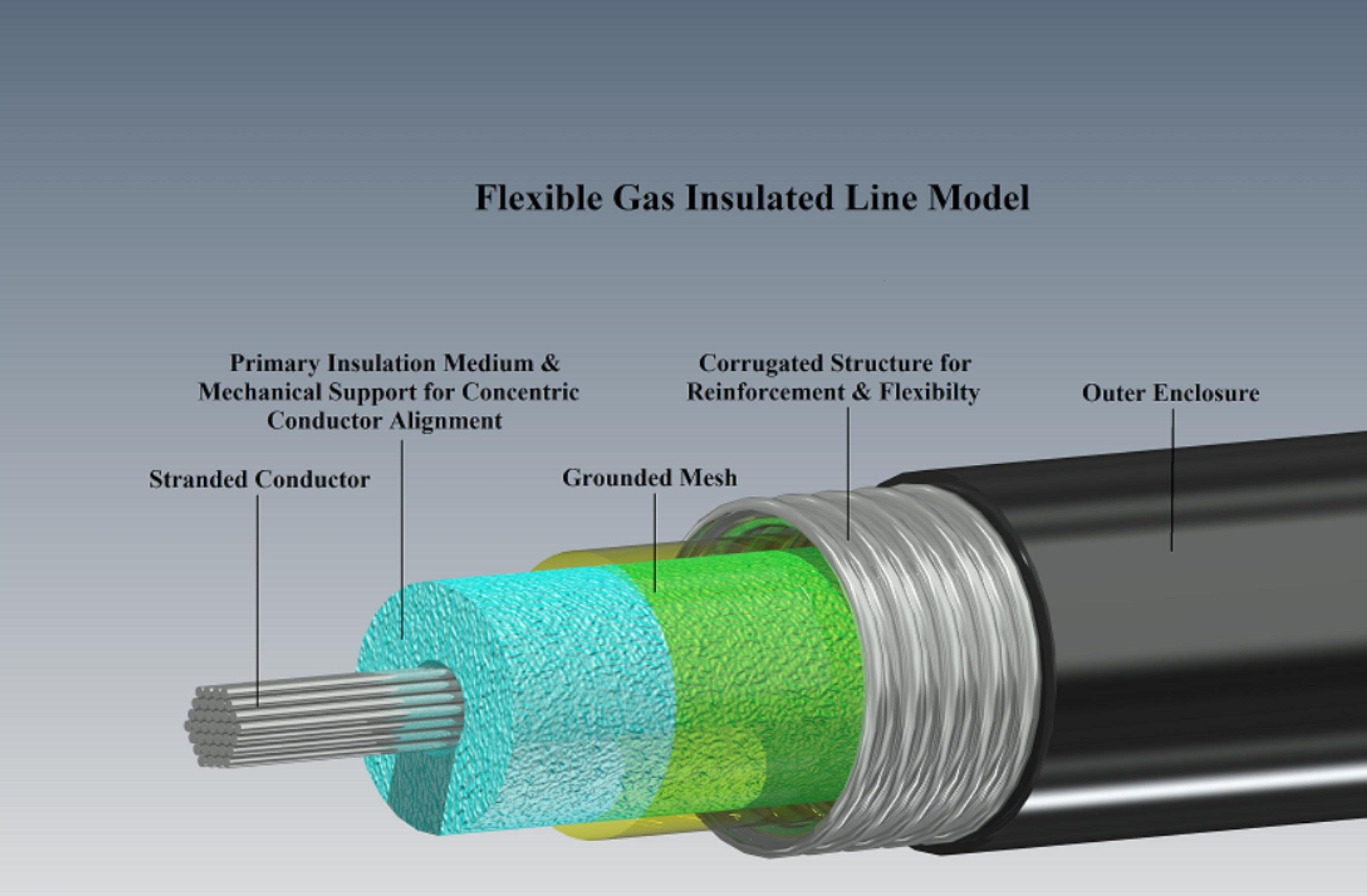
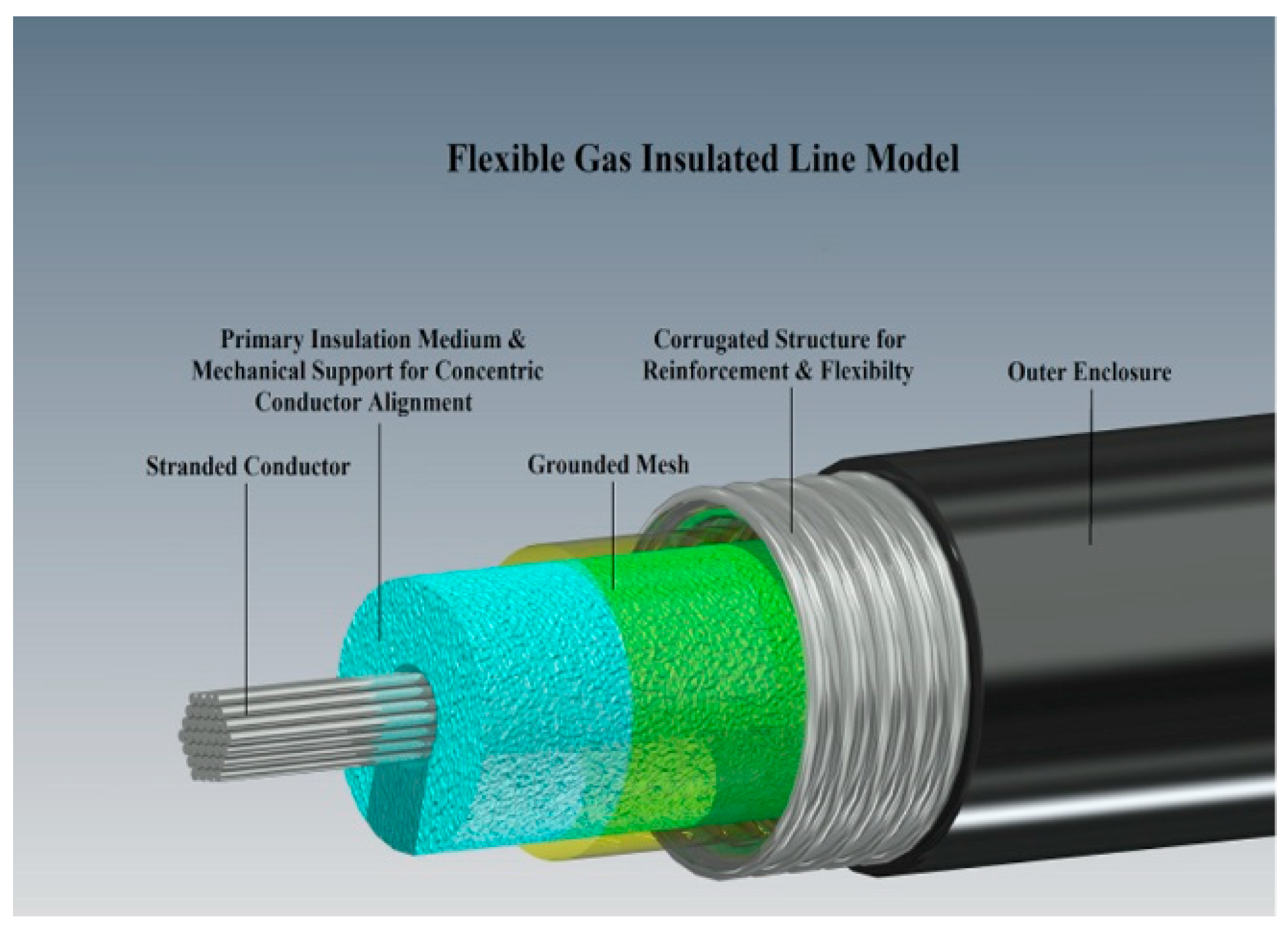
Regarding the simplification of intricacies associated with conventional GIL, a viable solution could be to substitute the inflexible hollow conductor with stranded aluminum conductor and rigid metallic enclosure with a flexible reinforced plastic (RP) enclosure. Further, conventional post insulators could be replaced with an open cell foam of suitable structural strength for mechanical support and concentric conductor alignment along with the added benefit of structural flexibility. Pliable GIL could eradicate the need for acceleration damper and corrosion protection along with the substantial reduction of minimum bending radius and required surface area at bends. In addition, structural flexibility of GIL will facilitate the horizontal directional drilling (HDD) based underground cable laying process and thus could significantly reduce the trench requirement regarding underground implementation of GIL.
Regarding the practical viability of proposed methodology, COMSOL Multiphysics® based electrostatic analysis is carried out for pliable GIL model in contrast to the conventional GIL model in order to identify the operational competency of proposed scheme. In addition, dimensional optimization for enclosure and pitch sizes regarding electrostatic stresses and field utilization is also performed for flexible GIL. Further experimental setup has been developed in order to analyze the synergistic effect of compressed insulating gases and open cell foam regarding their dielectric properties as open cell foam is proposed as a surrogate of post insulators.
2. Pliable Gas Insulated Transmission Line
Presently, metropolitan areas are suffering from land shortage due to escalating urbanization and impose restrictions upon implementing high voltage transmission lines in their vicinity. Flexible gas insulated lines could curtail various concerns regarding safety, land availability, aesthetics, economics and implementation of power transmission lines in metropolitan areas. Reinforced plastics (RP) are used in the manufacturing of high-pressure vessels regarding industrial applications as well as in the electrical systems as an insulation medium [
12,
13]. Having the desired properties regarding flexibility, chemical inertness, temperature, tensile and compressive strength, pressure and porosity, corrugated RP enclosure may serve as a feasible surrogate of metallic enclosure of conventional gas insulated line [
14]. Structural flexibility of the proposed scheme could be further enhanced by replacing the conventional conductor with stranded aluminum conductor, which is already being implemented in overhead transmission lines and underground power cables. In addition, the conventional rigid post insulators for concentric conductor alignment could be replaced with pliable open cell foam of appropriate structural strength [
15,
16,
17]. Open cell foam could serve as a flexible support for the conductor, without imposing complexities upon SF
6 gas flow and its insulation characteristics inside the GIL enclosure. Flexible conductor support in comparison to the conventional post insulator will also simplify the problem of pointed stress on line enclosure during bending and will enhance the line flexibility. Further, the desired electromagnetic compatibility of flexible GIL in comparison to the conventional GIL could be achieved by implementing a metallic mesh structure inside the corrugated enclosure. In comparison to the solid film, the mesh structure will be more suitable regarding line flexibility.
The proposed methodology will eliminate the necessity of trench development or excavation by implementing underground gas insulated line through Horizontal Directional Drilling (HDD) based underground cable laying scheme [
18,
19,
20].
Figure 1 represents the proposed model of flexible gas insulated transmission line.
3. Field Utilization Factor
Electric field stress in a region generally depends upon field homogeneity, gap distribution and electrode geometry. Field utilization factor could facilitate performing analytical field solutions regarding maximum electrical stress over the subject dielectric material. Conventional gas insulated lines comprise of a coaxial geometry and their field utilization factor could be evaluated through Equation (1) where
R1 is conductor radius and
R2 is enclosure radius [
21]. The field utilization factor for the proposed GIL scheme is evaluated through Equation (2) due to its corrugated enclosure profile.
3.1. Field Utilization Comparison
In order to perform electrostatic analysis, COMSOL Multiphysics
® based simulations are performed for conventional and proposed schemes and compared with practical evaluations for GIL model [
21]. Dimensional specifications of conductor and enclosure specimen like diameter, thickness and electrode gap were based upon the standard GIL model of 132 kV GIL and ASTM B232 standard [
8,
22]. Furthermore, the pitch size for the corrugated enclosure was based upon ASTM A760/A760M–10 standards for corrugated pipes [
10,
23]. Detailed specification of different GIL models used in the electrostatic appraisal is given in
Table 1.
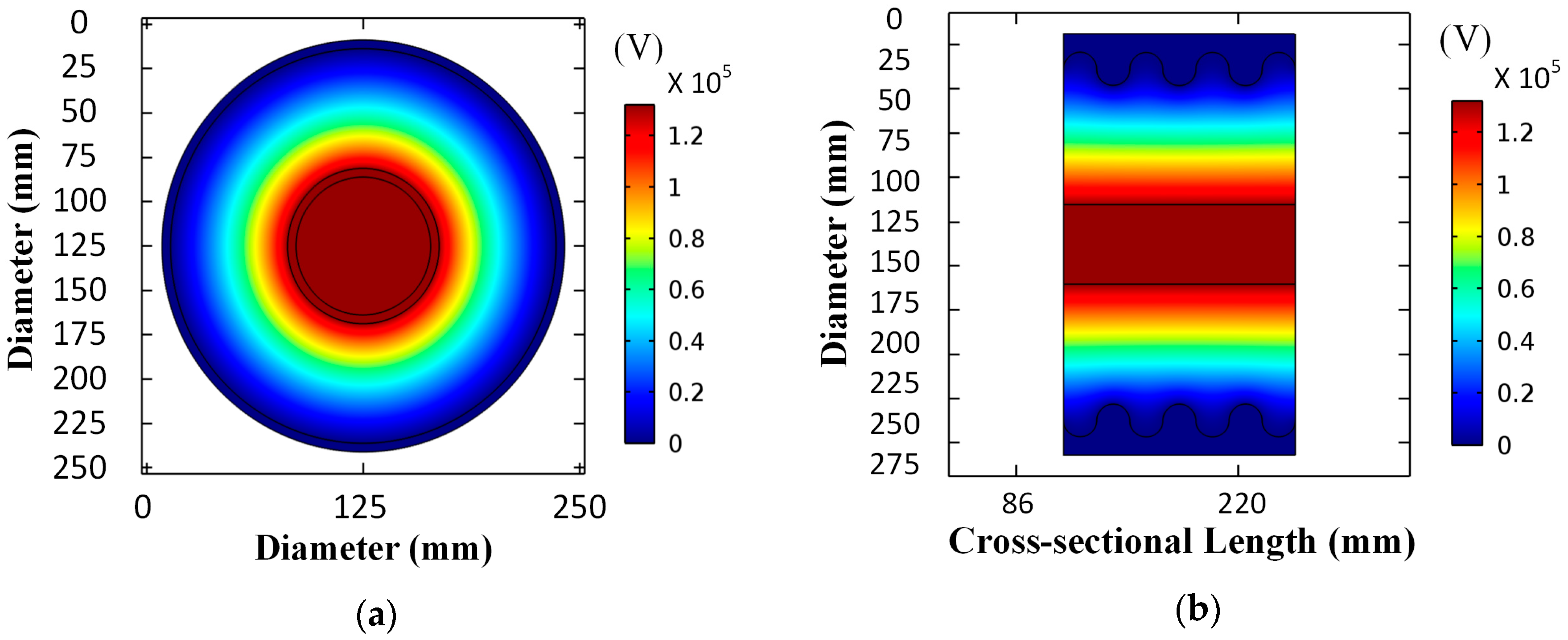
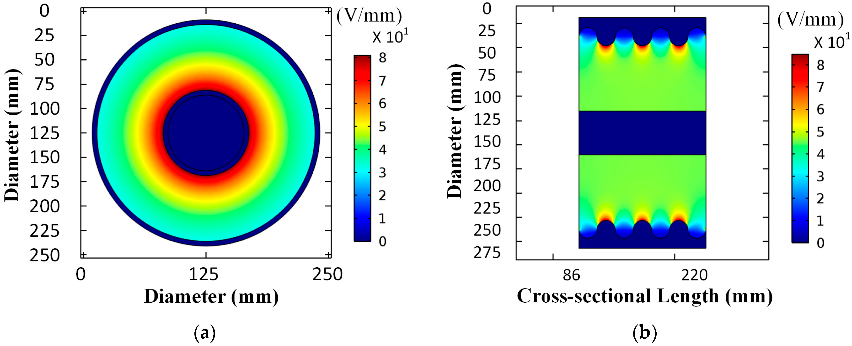
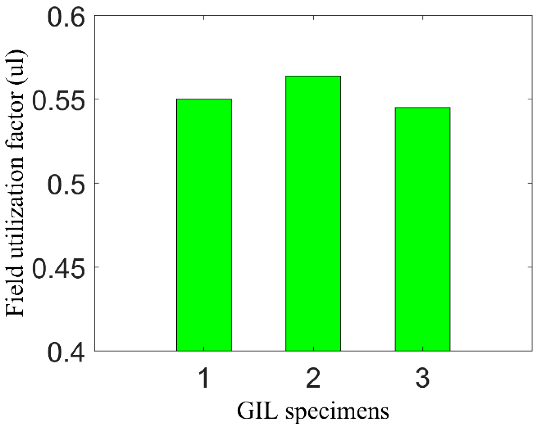
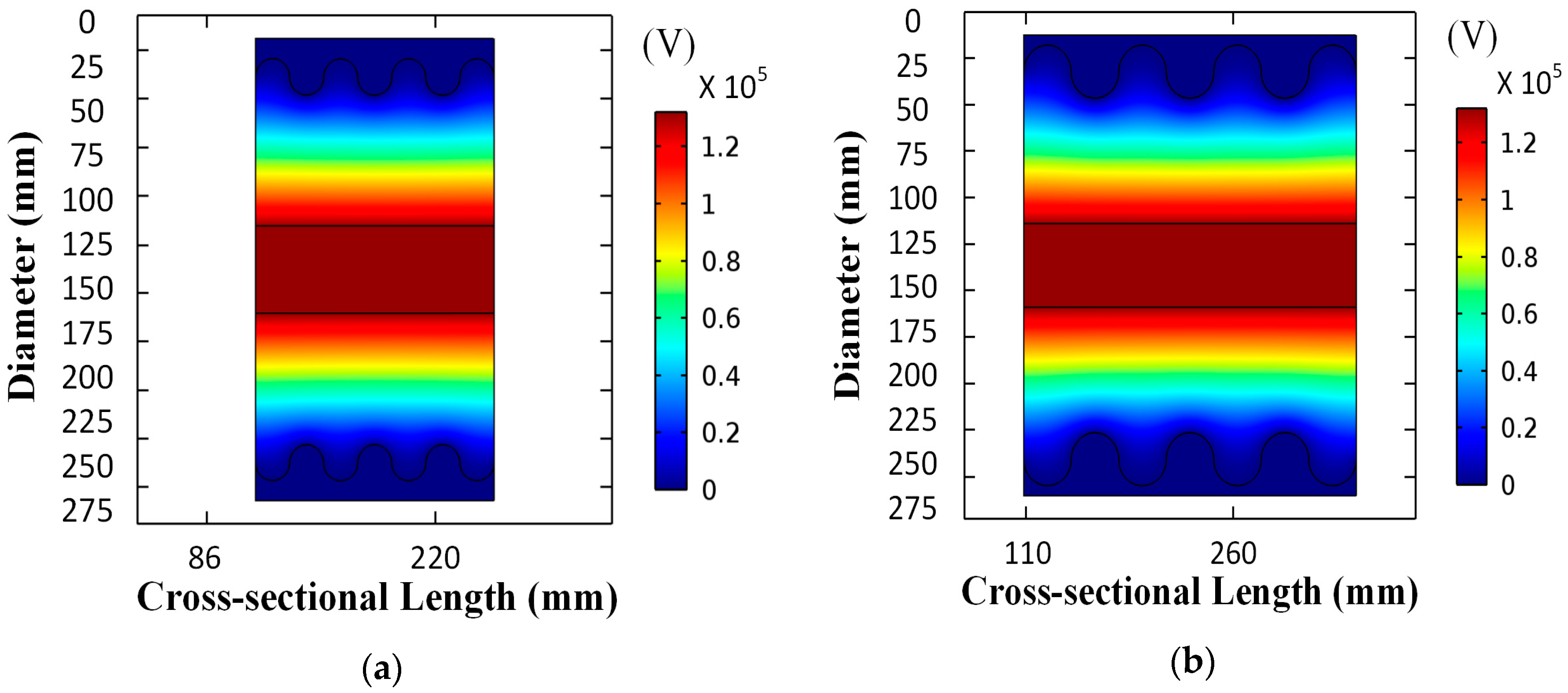
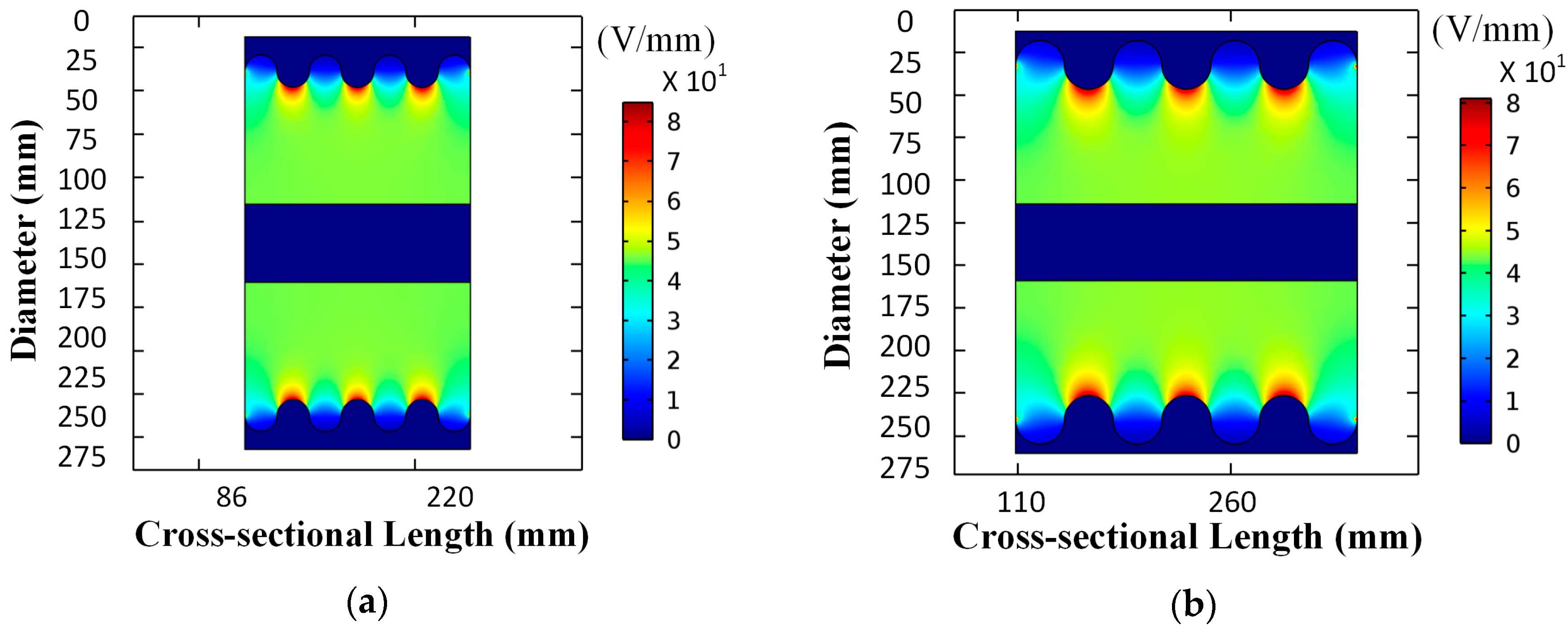
Figure 2 and
Figure 3 compare the electric potential and electric field distribution in conventional and proposed GIL schemes.
Figure 4 collates the field utilization factor for different GIL models of
Table 1 and represents a slight deviation of up to four percent in the proposed scheme as compared to the conventional scheme. This slight deviation is due to the corrugated enclosure profile and could be improved by optimizing the pitch size, curvature and gap length for optimal field utilization factor.
3.2. Gap Optimization
Field utilization factor is a function of gap length between high potential and ground electrodes. Thus, desired field utilization could be achieved by analyzing different electrode profiles and gaps. In order to optimize the field utilization factor for the proposed scheme, two flexible GIL models with pitch sizes of 38 mm and 58 mm were compared regarding the consequence of varied gap on field utilization factor. Detailed elucidation of different GIL models used in gap length optimization is given in
Table 2.
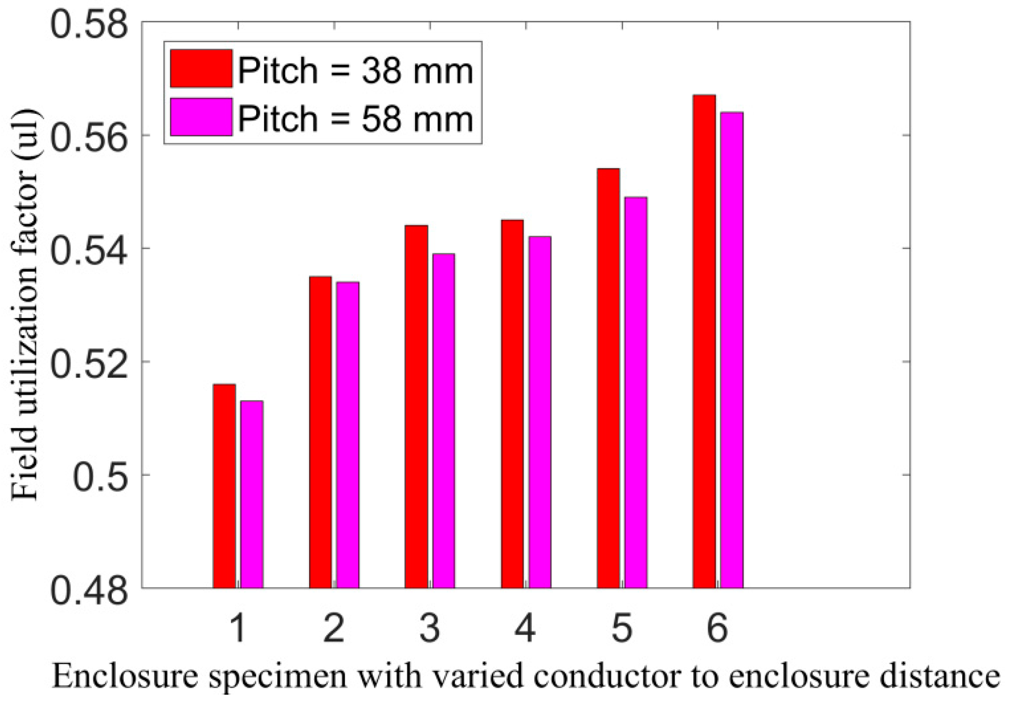
Figure 5 and
Figure 6 represent the simulation results regarding electric potential and electric field distribution in GIL models of different pitch sizes and gap lengths.
Figure 7 presents a comparison between different GIL models regarding the impact of varied pitch size and electrode gap over filed utilization factor. Critical analysis and comparison of
Figure 4 and
Figure 7 suggest that gap lengths of 58.5 mm and 68.5 mm regarding proposed GIL scheme have negligible deviations in field utilization factor, i.e., up to two percent as compared to the conventional GIL scheme. Thus, contemplating the space curbs regarding post insulator and close approximation with conventional GIL scheme of similar rating, gap length of 68.5 mm could be considered as the reasonable value.
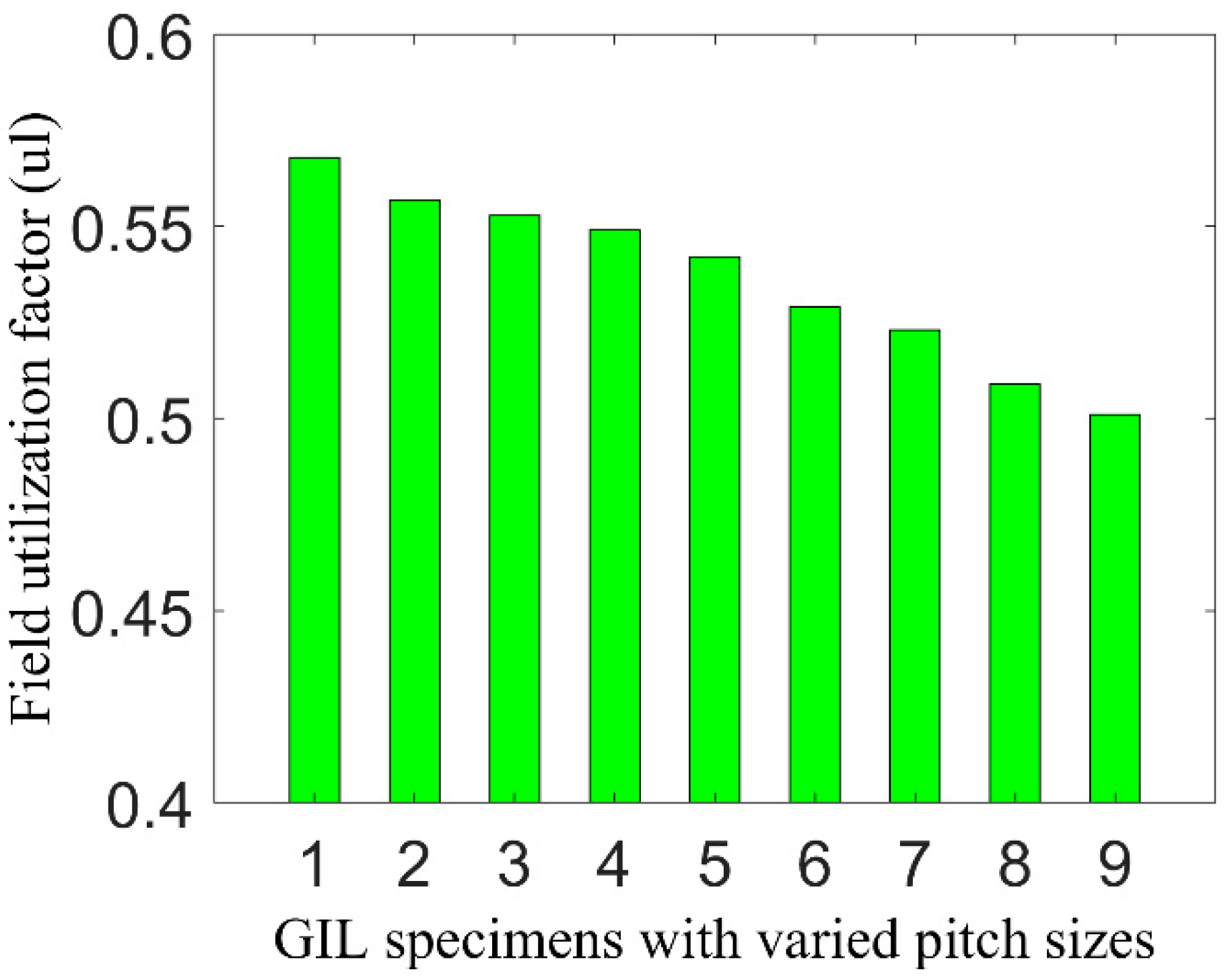
3.3. Pitch Optimization
Keeping in mind the significance of pitch dimension in model pliability and electrostatic performance, pitch optimization was performed using COMSOL Multiphysics
®. In this analysis, nine flexible GIL models having different pitch sizes and constant gap length, which are already optimized in above section were compared. Detailed elucidation of different pliable GIL models used in the analysis is given in
Table 3.
Figure 8 compares the field utilization factor for flexible GIL models given in
Table 3. Critical analysis and comparison of
Figure 4 and
Figure 8 represent that pitch sizes of 38 mm, 48 mm and 58 mm have minimal deviation in field utilization factor of up to four percent as compared to the conventional GIL scheme. Thus, contemplating the model flexibility and electrostatic characteristics, pitch size of 48 mm was considered as the optimal value.
4. Open Cell Foam
Foams are being used in industrial and commercial applications worldwide as filler, insulation, supporting material and as a dielectric material [
24,
25]. Polyurethane foams are already being used in low voltage and medium voltage applications and their characteristics for high voltage applications are under investigation [
16,
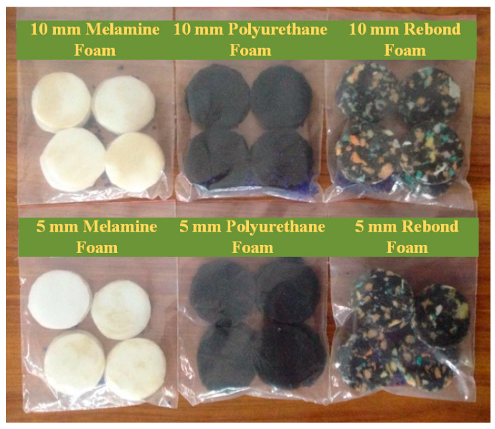
17]. Based upon their structure, foams could be categorized into two types i.e., open cell foams and closed cell foams. For pliable GIL scheme, open cell foam could be used to replace the post insulators in conventional GIL scheme. The proposed modification will enhance the structural flexibility of gas insulated lines without incorporating any complexity regarding corrugated enclosure profile. In this research, synergistic dielectric characteristics of open cell foams and insulation gases are studied through lightning impulse and disruptive discharge tests. Detailed description of different open cell foams used in the experimentation is given in
Table 4 and
Figure 9 shows the respective foam samples used in the test.
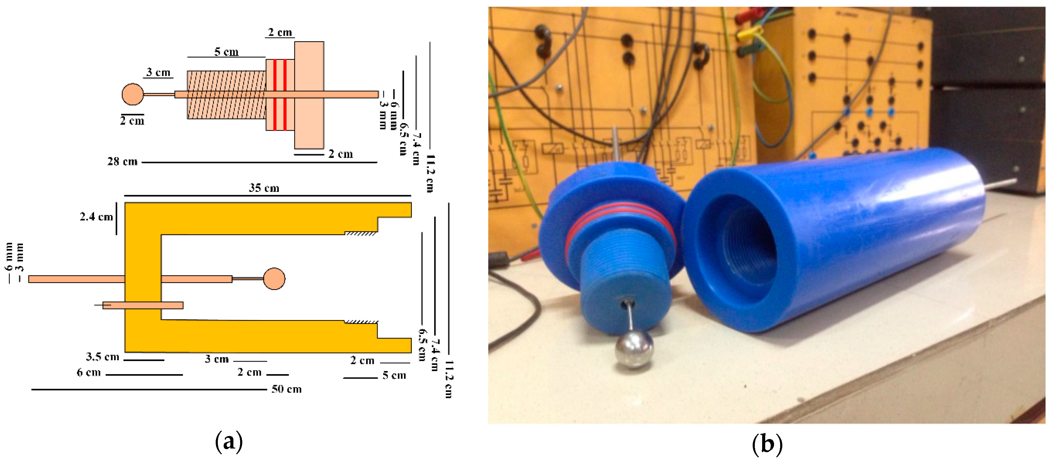
5. Standard Sphere Gap Arrangement
In order to conduct the high voltage experimental investigations, an enclosed sphere gap arrangement was designed and developed as per IEC 60052:2002 standard [
26]. The enclosed chamber was fabricated by boring a hole in Teflon cylinder and bore diameter was decided based on required clearances described by IEC 60052:2002 standard. After boring the cylinder’s inner surface was carefully smoothed in order to avoid any protrusions. The cylinder’s wall thickness was kept enough in order to withstand any gas pressure up to 100 psi. The electrodes of fabricated sphere gap discharge arrangement comprise of metallic spheres attached at the end of metallic rods. One of the two electrodes was made adjustable for investigating the dielectric properties of subject material at different gap lengths.
Further, gas filling system was incorporated in the chamber in order to create vacuum as well as to inject the compressed insulation gas in to the chamber at different pressures. In order to avoid any gas leakage, two slots were developed in the chamber’s lid for the implementation of O-rings. Furthermore, grooves for electrodes and pin valve were sealed appropriately with sufficient coating of Teflon tape.
Figure 10a shows the cross-sectional view and dimensional specifications of designed sphere gap discharge chamber whereas
Figure 10b presents its developed model for high voltage experimentation.
6. Experimental Setup
To investigate the practical feasibility of proposed insulation arrangement for pliable GIL, synergistic dielectric characteristics of various open cell foams with different insulation gases were observed in the laboratory. For the said purpose, lightning impulse and disruptive discharge tests were conducted as per IEC 60060-1:2010 standard for the foam specimens given in
Table 4 alone as well as in combination with air and SF
6 at different pressures [
27]. Regarding disruptive discharge, ten disruptive discharges were noted for each category and then their average was considered. However, regarding the lightning impulse discharge tests, up and down method was used and then 50% impulse disruptive discharge voltage U
50 for different categories was determined by using Equation (3).
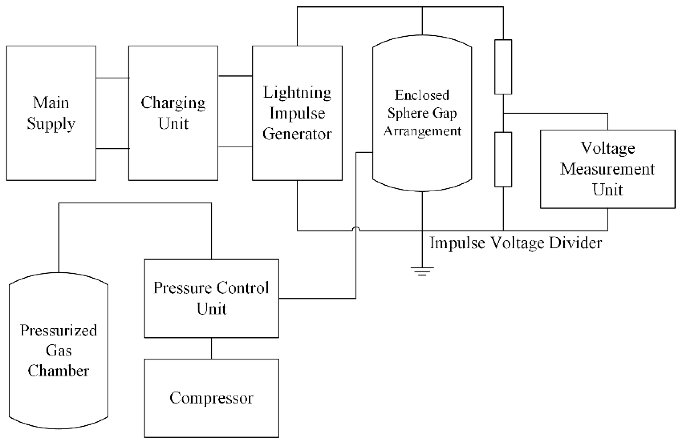
Figure 11 shows the block diagram for lightning impulse experiment where the enclosed sphere gap chamber is connected to the compressed gas vessel through a pressure control unit in order to control the gas pressure within the chamber. Furthermore, a compressor is also attached to the pressure control unit, in order to create vacuum in the sphere gap chamber before filling insulating gas at any desired pressure.
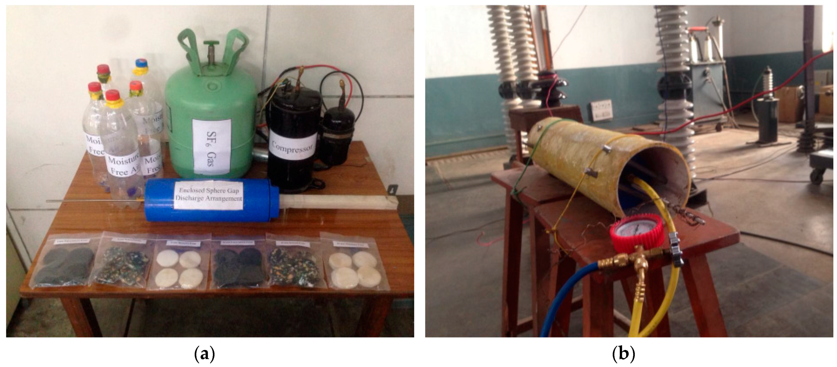
Figure 12a shows the various components used in the experimental investigations and
Figure 12b shows the test arrangement for lightning impulse and disruptive discharge tests in the high voltage laboratory.
7. Dielectric Breakdown Analysis
Conventional GIL is comprised of rigid post insulators to ensure concentric conductor alignment with in the enclosure. However, such supporting system would not be feasible in pliable GIL and will restrict the bending of line. Thus, high voltage tests were conducted with different open cell foams in conjunction with insulation gases, i.e., air and SF6 at different pressures in order to identify any adverse effect on the dielectric characteristics of insulation gases due to the proposed involvement of open cell foams in the enclosure.
7.1. Synergistic Breakdown Characteristics of Air and Open Cell Foams
In order to appraise the synergistic dielectric characteristics of open cell foams and air, the open cell foam specimens described in
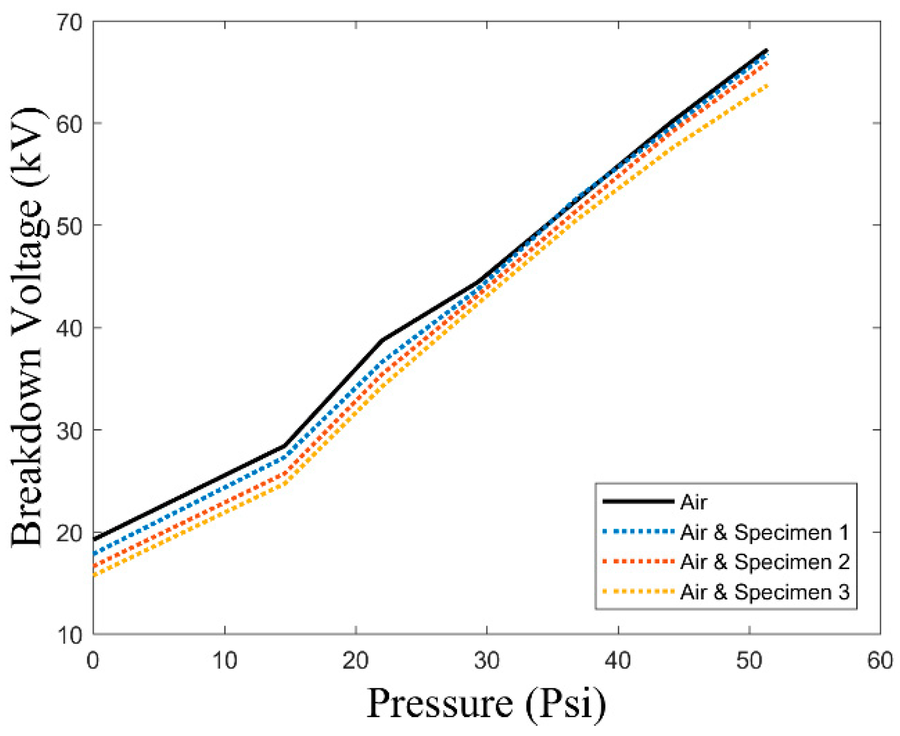
Table 4 were placed in the enclosed sphere gap chamber at a gap length of 10 mm. After creating vacuum in enclosed chamber, moisture free air was filled in to the chamber at pressures of 0, 14.6, 22.1, 29.3, 36.7, 44.1 and 51.4 psi.
Figure 13 shows the disruptive discharge test results of air alone and its combination with different specimens of
Table 4 at different pressures described above. Critical comparison of
Figure 13 unveils a maximum difference of 1.4 kV for specimen 1, 2.6 kV for specimen 2 and 3.3 kV for specimen 3 as compared to air alone at respective pressure, which is quite minimum.
Further, lightning impulse discharge tests of air alone, as well as in conjunction with different specimens of
Table 4, were performed at varying pressures described above and
Figure 14 compares the results of these tests. In comparison to air alone at respective pressures,
Figure 14 reveals a maximum variation of 3.9 kV for specimen 1, 6.8 kV for specimen 2 and 10.1 kV for specimen 3 which is quite reasonable.
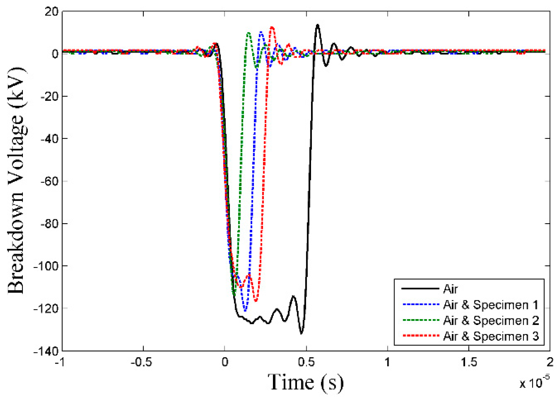
Figure 15 shows the recorded waveforms of lightning impulse discharge tests conducted at a pressure of 51.4 psi. Critical analysis of
Figure 13,
Figure 14 and
Figure 15 unveil that synergistic dielectric characteristics of open cell foams and air does not exhibit significant deviation from the dielectric characteristics of air alone at the respective pressures. Further dielectric characteristics in both categories i.e., air alone as well as in conjunction with open cell foams, vary somewhat in the similar pattern regarding pressure variation.
7.2. Synergistic Breakdown Characteristics of SF6 and Open Cell Foams
After analyzing the synergistic dielectric characteristics of air and open cell foams, similar high voltage tests were conducted with SF
6 gas in order to identify the validity of proposed scheme. Different open cell foam specimens described in
Table 4 were placed in the enclosed sphere gap chamber at a gap length of 7.5 mm. After creating vacuum in enclosed chamber, SF
6 gas was filled in to the chamber at pressures of 5, 10, 15, 20, 25 and 30 psi. Modifications in gap length and gas pressure were performed due to high voltage apparatus curbs regarding higher dielectric characteristics of SF
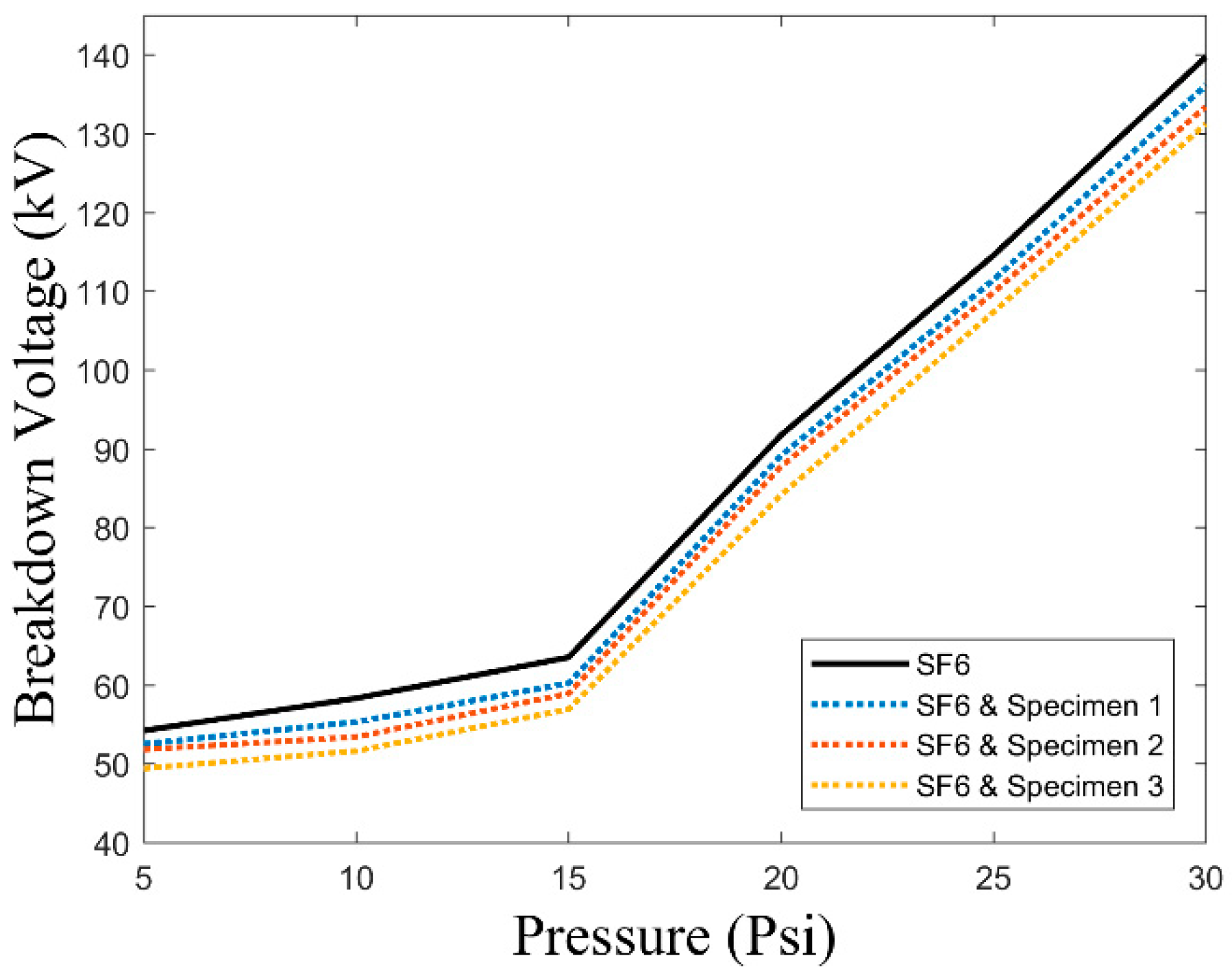
6 gas. Disruptive discharge tests of SF
6 alone as well as its combination with open cell foam specimens of
Table 4 were performed at different pressures mentioned above and
Figure 16 compares the results of these tests. In comparison to SF
6 alone at respective pressures,
Figure 16 unveils a maximum difference of 3 kV for specimen 1, 4.8 kV for specimen 2 and 6.7 kV for specimen 3 which is quite minimal.
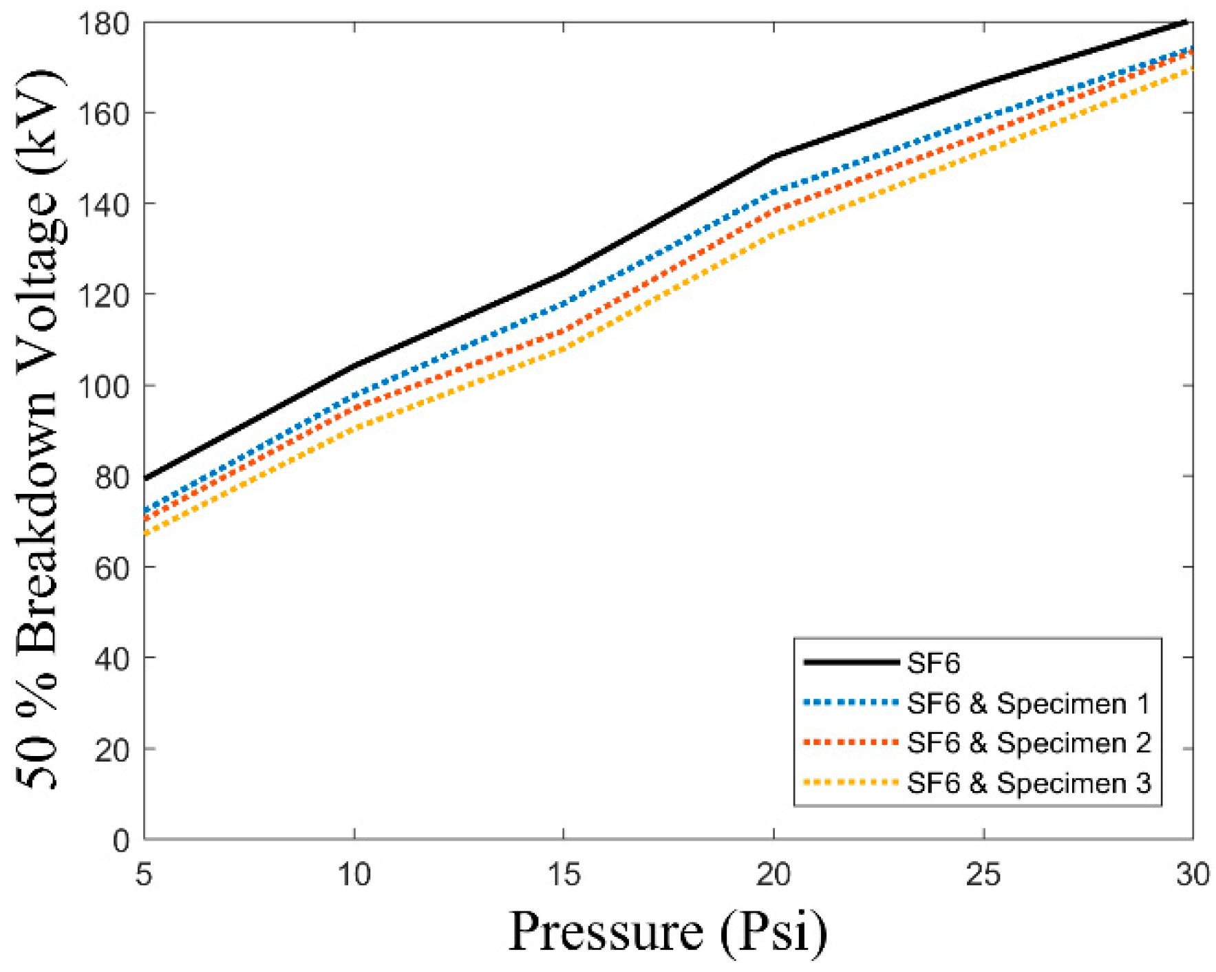
Figure 17 also shows the lightning impulse discharge test results of SF
6 alone as well as in conjunction with open cell foam specimens of
Table 4 at different pressures narrated above. Critical analysis of
Figure 17 reveals a maximum variation of 7.1 kV for specimen 1, 8.9 kV for specimen 2 and 12.1 kV for specimen 3 in comparison to SF
6 alone at respective pressures, which is quite reasonable.
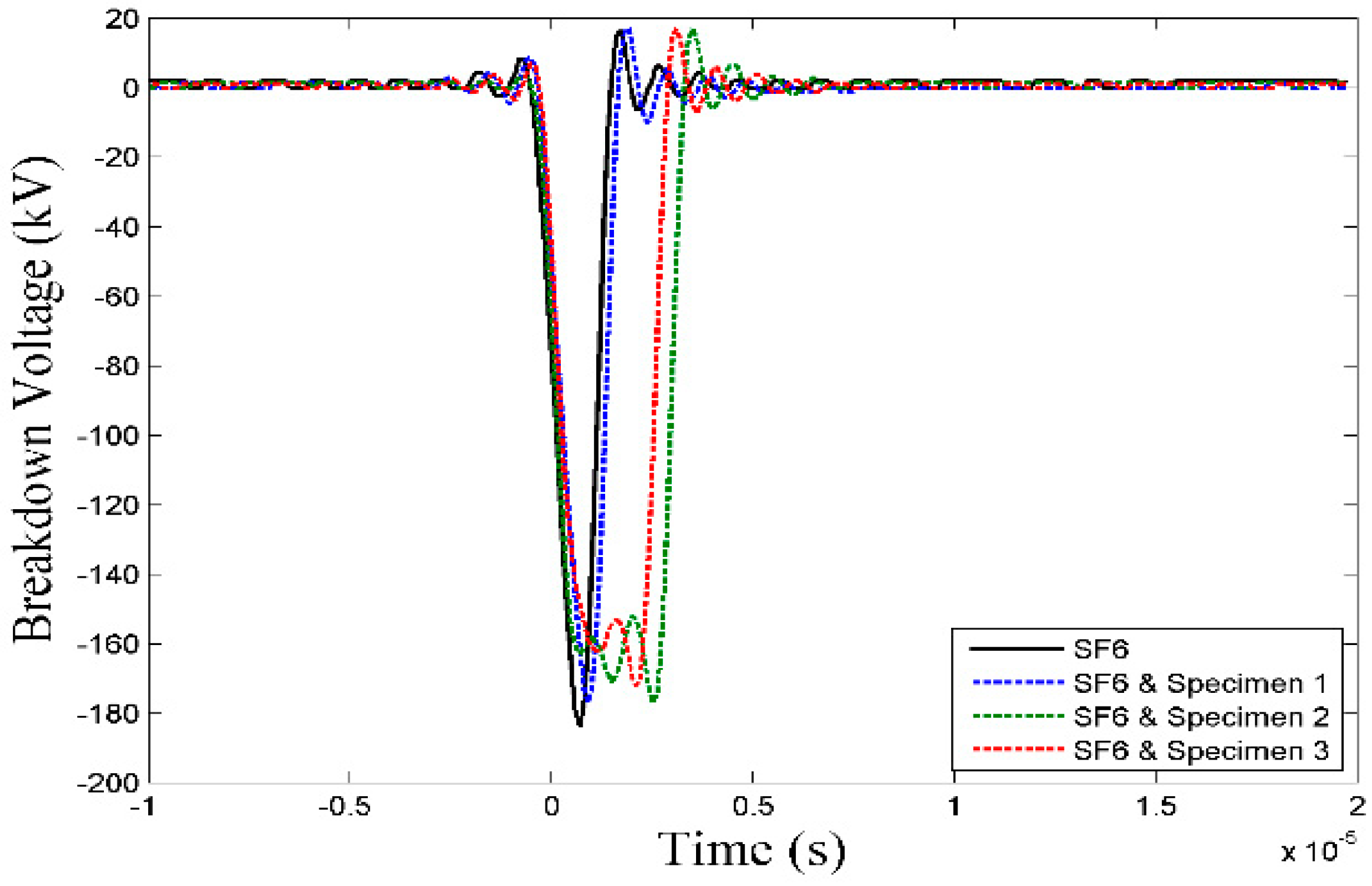
Figure 18 compares the recorded waveforms of lightning impulse discharge tests performed at 30 psi. Critical analysis of
Figure 16,
Figure 17 and
Figure 18 unveil that synergistic dielectric characteristics of open cell foams and SF
6 does not exhibit significant deviation from the dielectric characteristics of SF
6 alone at the respective pressures. Further dielectric characteristics in both categories, i.e., SF
6 alone as well as in conjunction with open cell foams vary almost in the similar pattern regarding pressure variation.
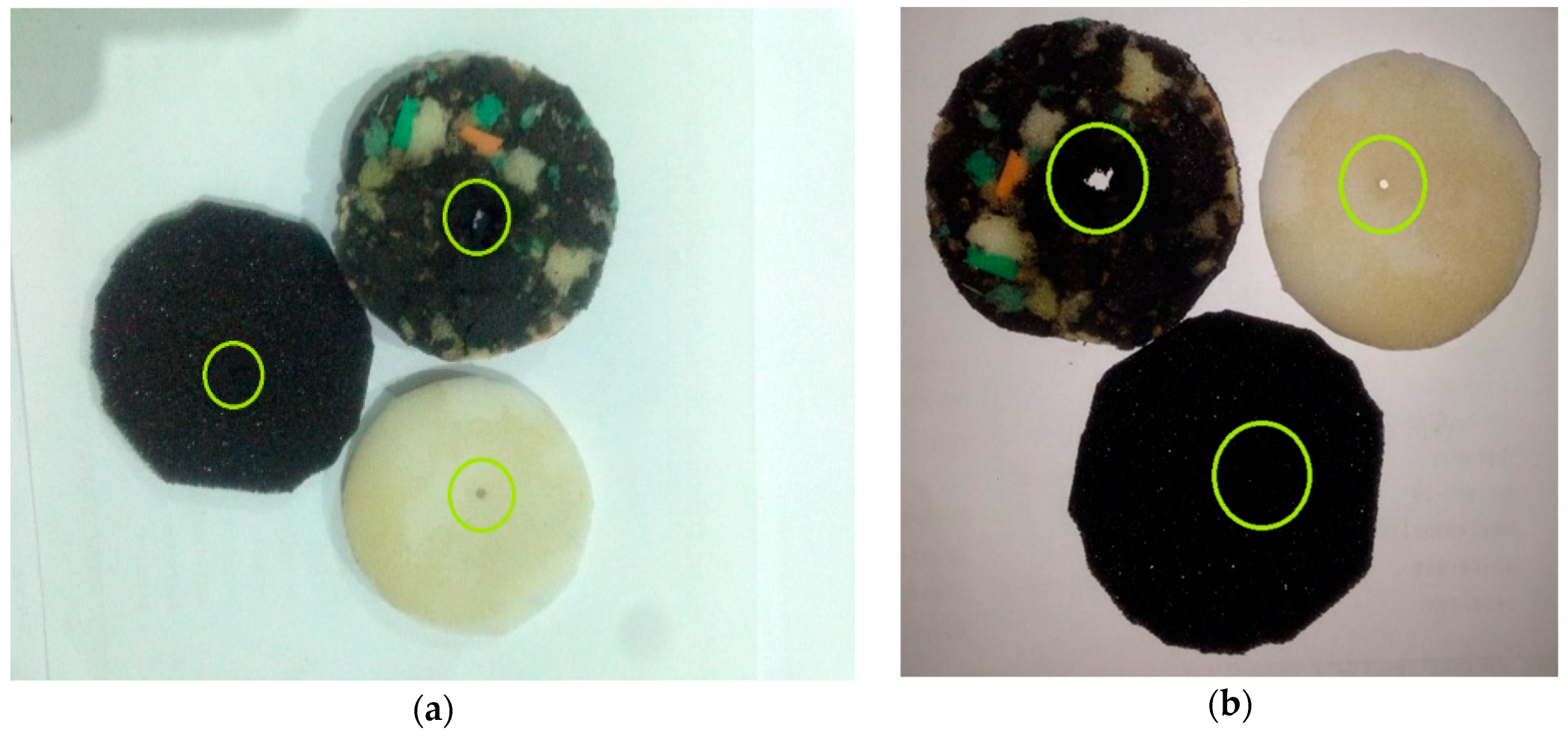
7.3. Specimen Analysis
After performing high voltage tests on different types of open cell foams, test specimens were analyzed regarding their respective puncture dimension and insulation degradation. Sample analysis revealed that lightning impulse tests resulted in an average insulation puncture diameter of 3.1 mm in specimen 1, 2.5 mm in specimen 2 and 2.1 mm in specimen 3. Similarly, an A.C. discharge test resulted in an average insulation puncture diameter of 4.6 mm in specimen 1, 3.3 mm in specimen 2 and 2.8 mm in specimen 3.
Figure 19 shows the lightning impulse discharge and disruptive discharge tested samples of different open cell foam specimens of
Table 4.
8. Conclusions
In this research paper, a new scheme of flexible GIL is proposed after performing its dielectric and electrostatic appraisal. Simulation results show that the proposed flexible GIL scheme exhibits nearly the same electrostatic behavior as compared to the conventional GIL with slight deviation of four percent in field utilization factor, which is quite minimal. In addition, pitch size of 48 mm and conductor to enclosure clearance of 68.5 mm could serve as the reasonably good selection with minimum deviation from conventional GIL of similar rating regarding electrical aspects with the added advantage of structural flexibility.
Further, high voltage experimental findings regarding synergistic dielectric characteristics of open cell foam and insulation gases unveil that open cell foams used in the experimentation does not significantly affect the dielectric characteristics of air and SF6. Specimen 1 and specimen 2 showed minimal deviation in synergistic lightning impulse and disruptive discharge tests i.e., up to 10 percent and 6 percent as compared to the respective tests with air and SF6 alone. Furthermore, variation in dielectric characteristics regarding pressure is observed nearly the same in respective categories of high voltage insulation tests. Thus, rebond foam or polyurethane foam of sufficient structural strength could be used as a substitute of conventional post insulator for concentric conductor alignment without significantly compromising the dielectric characteristics of primary insulation medium in gas insulated lines. Flexible conductor support will facilitate line bending without imposing pointed stress on enclosure as compared to conventional post insulators.
Thus, the proposed modifications could facilitate in developing flexible GIL without significantly compromising the electrostatic and dielectric aspects of conventional GIL along with the added benefit of cost reduction.
Author Contributions
Conceptualization, M.J.A., T.I. and A.A.Q.; Formal analysis, M.J.A., T.I. and A.A.Q.; Investigation, M.J.A.; Methodology, M.J.A., T.I. and A.A.Q.; Software, M.J.A.; Supervision, T.I. and A.A.Q.; Writing—original draft, M.J.A.; Writing—review & editing, T.I. and A.A.Q.
Funding
This research received no external funding.
Conflicts of Interest
The authors declare no conflict of interest.
References
- Koch, H. Gas Insulated Transmission Lines (GIL); John Wiley & Sons: Hoboken, NJ, USA, 2011. [Google Scholar]
- McDonald, J.D. Electric Power Substations Engineering; CRC Press: Boca Raton, FL, USA, 2016. [Google Scholar]
- Koch, H.; Goll, F.; Magier, T.; Juhre, K. Technical aspects of gas insulated transmission lines and application of new insulating gases. IEEE Trans. Dielectr. Electr. Insul. 2018, 25, 1448–1453. [Google Scholar] [CrossRef]
- Poehler, S.; Rudenko, P. Directly buried gas-insulated transmission lines (GIL). In Proceedings of the 2012 IEEE PES Transmission and Distribution Conference and Exposition (T&D), Orlando, FL, USA, 7–10 May 2012; pp. 1–5. [Google Scholar]
- Li, B.; Gu, T.; Li, B.; Zhang, Y. Study on the gas-insulated line equivalent model and simplified model. Energies 2017, 10, 901. [Google Scholar] [CrossRef]
- Sarajcev, P. Numerical analysis of the magnetic field of high-current busducts and GIL systems. Energies 2011, 4, 2196–2211. [Google Scholar] [CrossRef]
- Chakir, A.; Koch, H. Corrosion protection for gas-insulated transmission lines. In Proceedings of the 2002 IEEE Power Engineering Society Summer Meeting, Chicago, IL, USA, 21–25 July 2002; pp. 220–224. [Google Scholar]
- Benato, R.; Di Mario, C.; Koch, H. High-capability applications of long gas-insulated lines in structures. IEEE Trans. Power Deliv. 2007, 22, 619–626. [Google Scholar] [CrossRef]
- Chakir, A.; Koch, H. Seismic calculations of directly buried gas-insulated transmission lines (GIL). In Proceedings of the Transmission and Distribution Conference and Exhibition 2002, Asia Pacific, Yokohama, Japan, 6–8 October 2002; pp. 1026–1029. [Google Scholar]
- Koch, H.J. Super session ‘vision 2020’ieee general meeting 2008 application of long high capacity gas insulated lines in structures. In Proceedings of the 2008 IEEE Power and Energy Society General Meeting-Conversion and Delivery of Electrical Energy in the 21st Century, Pittsburgh, PA, USA, 20–24 July 2008; pp. 1–5. [Google Scholar]
- Benato, R.; Carlini, E.M.; Di Mario, C.; Fellin, L.; Paolucci, A.; Turri, R. Gas insulated transmission lines in railway galleries. IEEE Trans. Power Deliv. 2005, 20, 704–709. [Google Scholar] [CrossRef]
- Tuncer, E.; Sauers, I.; James, D.R.; Ellis, A.R. Electrical insulation characteristics of glass fiber reinforced resins. IEEE Trans. Appl. Supercond. 2009, 19, 2359–2362. [Google Scholar] [CrossRef]
- Onder, A.; Sayman, O.; Dogan, T.; Tarakcioglu, N. Burst failure load of composite pressure vessels. Compos. Struct. 2009, 89, 159–166. [Google Scholar] [CrossRef]
- Xia, Y.; Wang, W.; Tao, C.; Li, C.; He, S.; Chen, W. Application of newly developed epoxy-anhydride vpi resin for high voltage motors and generators. In Proceedings of the 2015 IEEE Electrical Insulation Conference (EIC), Seattle, WA, USA, 7–10 June 2015; pp. 511–514. [Google Scholar]
- Qiu, X.; Groth, F.; Wirges, W.; Gerhard, R. Cellular polypropylene foam films as dc voltage insulation and as piezoelectrets—A comparison. IEEE Trans. Dielectr. Electr. Insul. 2018, 25, 829–834. [Google Scholar] [CrossRef]
- Argin, M.; Karady, G. Characterization of polyurethane foam dielectric strength. IEEE Trans. Dielectr. Electr. Insul. 2008, 15, 350–356. [Google Scholar] [CrossRef]
- Karady, G.G.; Argin, M.; Rahmatian, F.; Rose, A. Polyurethane foam application for high voltage insulation. In Proceedings of the 2004 Annual Report Conference on Electrical Insulation and Dielectric Phenomena, CEIDP’04, Boulder, CO, USA, 20 October 2004; pp. 526–529. [Google Scholar]
- Shang, M.; Xu, Q.; Xue, Y. Application of guided boring trenchless technology on pipeline cross railway. In Proceedings of the 2011 International Conference on Multimedia Technology (ICMT), Hangzhou, China, 26–28 July 2011; pp. 975–978. [Google Scholar]
- Bascom, E.C.R.; Rezutko, J. Novel installation of a 138kv pipe-type cable system under water using horizontal directional drilling. In Proceedings of the 2014 IEEE PES T&D Conference and Exposition, Chicago, IL, USA, 14–17 April 2014; pp. 1–5. [Google Scholar]
- Black, S.; Cable, B.; Fredrickson, B.; Warren, D. Horizontal directional drilling cable shorelanding at san nicolas island, California. In Proceedings of the MTTS/IEEE TECHNO-OCEAN’04, Kobe, Japan, 9–12 November 2004; pp. 2104–2111. [Google Scholar]
- Chen, L.; Griffiths, H.; Haddad, A.; Kamarudin, M. Breakdown of cf 3 i gas and its mixtures under lightning impulse in coaxial-GIL geometry. IEEE Trans. Dielectr. Electr. Insul. 2016, 23, 1959–1967. [Google Scholar] [CrossRef]
- Chromatography, B.M.E.B.G; The American Society for Testing and Materials: West Conshohocken, PA, USA, 1898.
- AASHTO, M. 36. Standard Specification for Corrugated Steel Pipe, Metallic-Coated for Sewers and Drains; American Association of State and Highway Transportation Officials: Washington, DC, USA, 2007. [Google Scholar]
- Zhu, Y.; He, L.; Zhou, S.; Zhang, D.; Fang, J. Insulation performance of rigid polyurethane foam and its application in station post insulator. In Proceedings of the 2018 12th International Conference on the Properties and Applications of Dielectric Materials (ICPADM), Xi’an, China, 20–24 May 2018; pp. 970–973. [Google Scholar]
- Liang, X.; Shen, Y.; Liu, Y.; Wang, J.; Gao, Y.; Li, S.; Wang, M.; Gao, S. Investigations on the basic electrical properties of polyurethane foam material. In Proceedings of the 2015 IEEE 11th International Conference on the Properties and Applications of Dielectric Materials (ICPADM), Sydney, NSW, Australia, 19–22 July 2015; pp. 863–866. [Google Scholar]
- International Electrotechnical Commission. 60052. Voltage Measurement by Means of Standard Air Gaps; IEC Std: Geneva, Switzerland, 2002; pp. 23–27. [Google Scholar]
- International Electrotechnical Commission. 60060-1. High Voltage Test Techniques—Part 1: General Definitions and Test Requirements; IEC Std: Geneva, Switzerland, 2010; pp. 67–79. [Google Scholar]
© 2018 by the authors. Licensee MDPI, Basel, Switzerland. This article is an open access article distributed under the terms and conditions of the Creative Commons Attribution (CC BY) license (http://creativecommons.org/licenses/by/4.0/).


