A Hierarchical Control Methodology for Renewable DC Microgrids Supporting a Variable Communication Network Health

 , ,
, ,
Abstract
:1. Introduction
- Every node stores the information about network links, and on that basis detects communication islanding with minimum data exchange.
- After detecting communication link failure, the proposed algorithm modifies the control to maintain operation and stability. In this manner, every node can act quickly to maintain the network variables for a reliable operation and control.
- A small signal model is used to check the system stability during communication islanding.
2. Communication Link Failure and Impacts
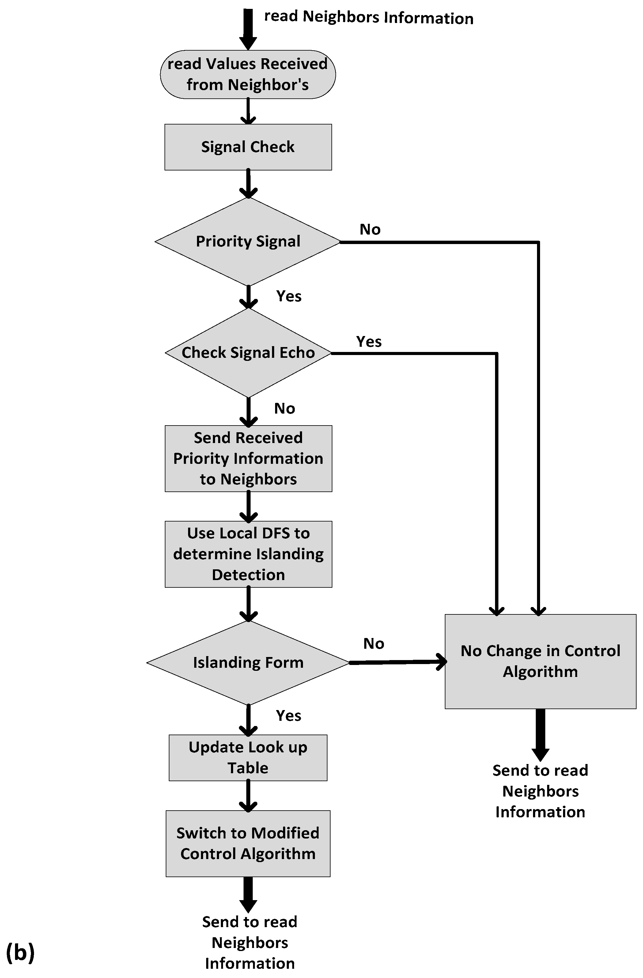
3. Islanding Detection Algorithm
Graphical Representation and Cutset Formation
| Algorithm 1 Depth-first search for graph , where is the adjacency list for |
| Require: A graph represents the physical topology for a DC microgrid. Ensure: the connectivity using DFS and generate look-up table. START Integer k; Routine ; Comment vertex is the parent vertex for vertex in the spanning tree constructed START NUMBER : = k; FOR is the adjacency list if DO START IF is not yet numbered THEN START Construct arc in ; END ELSE IF NUMBER < NUMBER and THEN construct arc in END; END; ; END; |
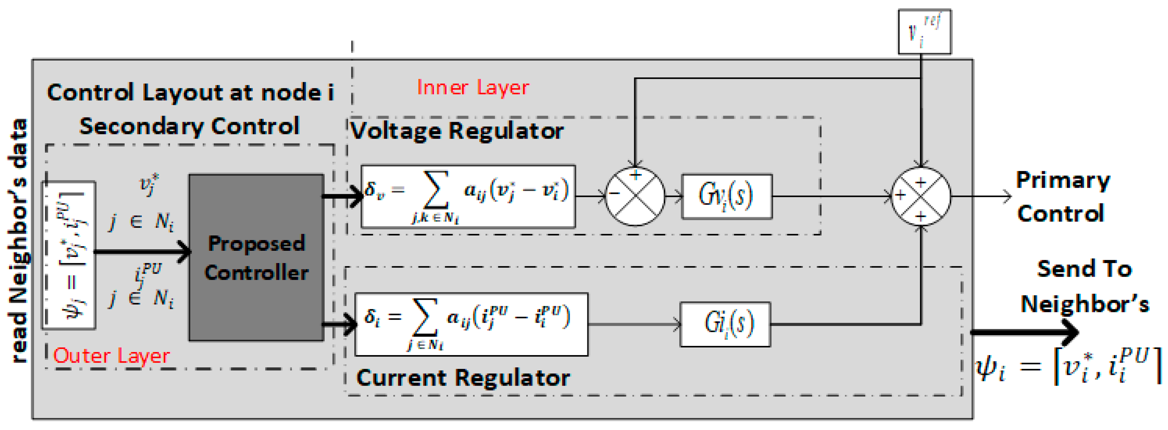
4. Control Scheme
4.1. Regular Connected Communication Mode
4.2. Communication Islanding Mode
4.3. System Modeling
4.3.1. One-Node Model
4.3.2. Overall DC MG System Model
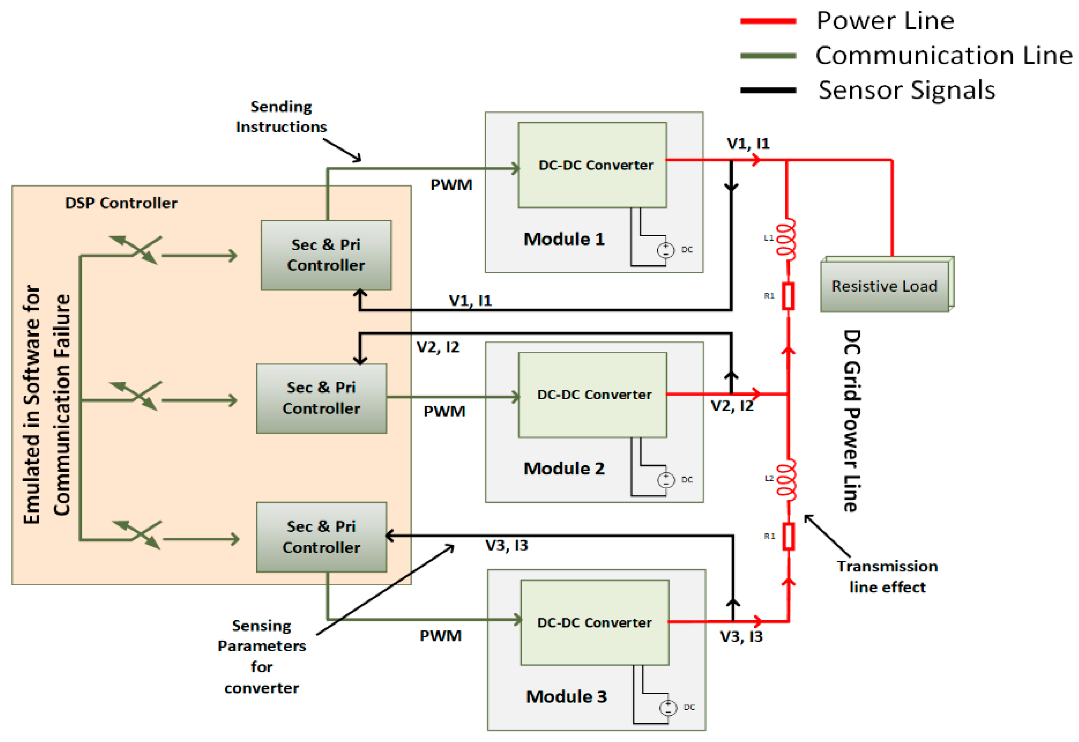
5. Case Study
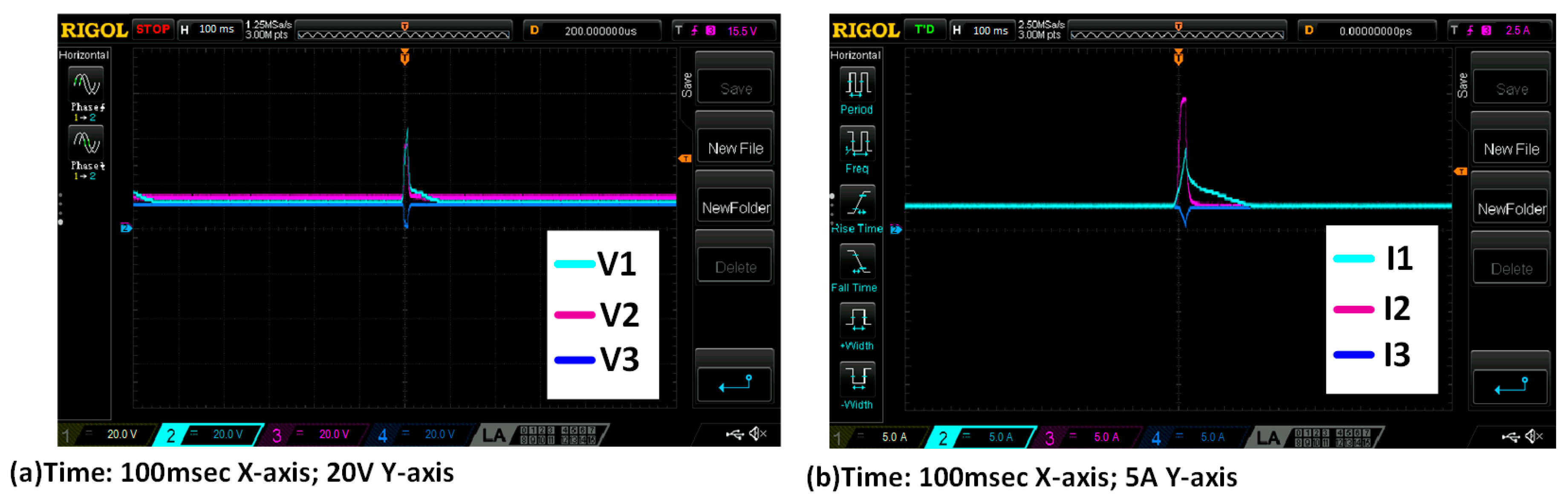
6. Experimental Results
7. Conclusions
Author Contributions
Funding
Conflicts of Interest
References
- Lotfi, H.; Member, S.; Khodaei, A. AC Versus DC Microgrid Planning. IEEE Trans. Power Syst. 2017, 8, 296–304. [Google Scholar] [CrossRef]
- Kan, N.H.; Kanjiya, P.; Zeineldin, H.H.; Xiao, W.; Kirtley, J.L.; Khadkikar, V. A Modified Control Topology to Improve Stability Margins in Micro-grids with Droop Controlled IBDG. In Proceedings of the 3rd Renewable Power Generation Conference (RPG 2014), Naples, Italy, 24–25 September 2014; pp. 1–7. [Google Scholar] [CrossRef]
- Standards, I.; Committee, C.; Generation, D.; Storage, E. IEEE Guide for Design, Operation, and Integration of Distributed Resource Island Systems with Electric Power Systems; IEEE: Piscataway, NJ, USA, 2011; ISBN 9780738166889. [Google Scholar]
- Bunker, K.J.; Weaver, W.W. Multidimensional droop control for wind resources in dc microgrids. IET Gener. Transm. Distrib. 2017, 11, 657–664. [Google Scholar] [CrossRef]
- Behjati, H.; Davoudi, A.; Lewis, F. Modular DC-DC Converters on Graphs: Cooperative Control. IEEE Trans. Power Electron. 2014, 29, 6725–6741. [Google Scholar] [CrossRef]
- Habib, S.; Khan, M.M.; Abbas, F.; Sang, L.; Shahid, M.U.; Tang, H. A comprehensive study of implemented international standards, technical challenges, impacts and prospects for electric vehicles. IEEE Access 2018, 6, 13866–13890. [Google Scholar] [CrossRef]
- Habib, S.; Kamran, M.; Rashid, U. Impact analysis of vehicle-to-grid technology and charging strategies of electric vehicles on distribution networks—A review. J. Power Sources 2015, 277, 205–214. [Google Scholar] [CrossRef]
- Moayedi, S.; Davoudi, A. Distributed Tertiary Control of DC Microgrid Clusters. IEEE Trans. Power Electron. 2016, 31, 1717–1733. [Google Scholar] [CrossRef]
- Hossain, M.S.; Madlool, N.A.; Rahim, N.A.; Selvaraj, J.; Pandey, A.K.; Khan, A.F. Role of smart grid in renewable energy: An overview. Renew. Sustain. Energy Rev. 2016, 60, 1168–1184. [Google Scholar] [CrossRef]
- Wang, P.; Xiao, J.; Setyawan, L. Hierarchical Control of Hybrid Energy Storage System in DC Microgrids. IEEE Trans. Ind. Electron. 2015, 62, 4915–4924. [Google Scholar] [CrossRef]
- Frances, A.; Asensi, R.; Garcia, O.; Prieto, R.; Uceda, J. Modeling Electronic Power Converters in Smart DC Microgrids—An Overview. IEEE Trans. Smart Grid 2018, 9, 6274–6287. [Google Scholar] [CrossRef]
- Takahashi, T.; Miyamoto, M.; Dousoky, G.M.; Shoyama, M. Droop control for bi-directional DC-DC converters used in multi-level virtual conductors. In Proceedings of the 2015 IEEE International Telecommunications Energy Conference (INTELEC), Osaka, Japan, 12–22 October 2015. [Google Scholar] [CrossRef]
- Lu, X.; Guerrero, J.M.; Sun, K.; Vasquez, J.C. An improved droop control method for dc microgrids based on low bandwidth communication with dc bus voltage restoration and enhanced current sharing accuracy. IEEE Trans. Power Electron. 2014, 29, 1800–1812. [Google Scholar] [CrossRef]
- Nasirian, V.; Member, S.; Moayedi, S.; Member, S.; Davoudi, A.; Lewis, F.L. Distributed Cooperative Control of DC Microgrids. IEEE Trans. Power Electron. 2015, 30, 2288–2303. [Google Scholar] [CrossRef]
- Lee, Z.; Zhu, S.; Zheng, J.; Choi, D.H.; Wei, L. Research on Dynamic Process of DC Micro-grid under Hierarchical Control. In Proceedings of the 19th IFAC World Congress, Cape Town, South Africa, 24–29 August 2014; Volume 47, ISBN 9783902823625. [Google Scholar]
- Hu, T.; Khan, M.M.; Xu, K.; Zhou, L.; Rana, A. Design of an input-parallel output-parallel multi-module DC-DC converter using a ring communication structure. J. Power Electron. 2015, 15, 886–898. [Google Scholar] [CrossRef]
- Kang, W.; Li, Q.; Gao, M.; Li, X.; Wang, J.; Xu, R.; Chen, M. Distributed Secondary Control Method for Islanded Microgrids with Communication Constraints. IEEE Access 2018, 6, 5812–5821. [Google Scholar] [CrossRef]
- Tanyingyong, V.; Olsson, R.; Cho, J.; Hidell, M.; Sj, P. IoT-grid: IoT Communication for Smart DC Grids. In Proceedings of the Global Communications Conference (GLOBECOM), Washington, DC, USA, 4–8 December 2016. [Google Scholar]
- Lewis, F.L.; Zhang, H.; Hengster-Movric, K.; Das, A. Cooperative Control of Multi-Agent Systems; Springer: London, UK, 2014; Volume 53, ISBN 978-1-4471-5573-7. [Google Scholar]
- Lewis, F.L.; Qu, Z.; Davoudi, A.; Bidram, A. Secondary control of microgrids based on distributed cooperative control of multi-agent systems. IET Gener. Transm. Distrib. 2013, 7, 822–831. [Google Scholar] [CrossRef]
- Oliveira, T.R.; Silva, W.W.; Donoso-Garcia, P.F. Distributed Secondary Level Control for Energy Storage Management in DC Microgrids. IEEE Trans. Smart Grid 2017, 8, 2597–2607. [Google Scholar] [CrossRef]
- Meng, L.; Shafiee, Q.; Trecate, G.F.; Karimi, H.; Fulwani, D.; Lu, X.; Guerrero, J.M. Review on Control of DC Microgrids and Multiple Microgrid Clusters. IEEE J. Emerg. Sel. Top. Power Electron. 2017, 5, 928–948. [Google Scholar] [CrossRef]
- Hug, G.; Kar, S.; Wu, C. Consensus + innovations approach for distributed multiagent coordination in a microgrid. IEEE Trans. Smart Grid 2015, 6, 1893–1903. [Google Scholar] [CrossRef]
- Kumar, S.; Das, N.; Islam, S. Performance monitoring of a PMU in a microgrid environment based on IEC 61850-90-5. In Proceedings of the 2016 Australasian Universities Power Engineering Conference (AUPEC), Brisbane, Australia, 25–28 September 2016; pp. 1–5. [Google Scholar]
- Dou, C.; Yue, D.; Guerrero, J.M.; Xie, X.; Hu, S. Multiagent system-based distributed coordinated control for radial dc microgrid considering transmission time delays. IEEE Trans. Smart Grid 2016, 8, 2370–2381. [Google Scholar] [CrossRef]
- Hare, J.; Shi, X.; Gupta, S.; Bazzi, A. Fault diagnostics in smart micro-grids: A survey. Renew. Sustain. Energy Rev. 2016, 60, 1114–1124. [Google Scholar] [CrossRef]
- Mah, D.; Hills, P.; Li, V.O.K.; Richard, B. Smart grid applications and developments. In Green Energy and Technology; Springer: London, UK, 2014; ISBN 978-1-4471-6280-3. [Google Scholar]
- Konara, K.M.; Kolhe, M.L. Charging management of grid integrated battery for overcoming the intermittency of RE sources. In Proceedings of the IEEE International Conference on Information and Automation for Sustainability (ICIAfS), Galle, Sri Lanka, 16–19 Decmber 2016. [Google Scholar] [CrossRef]
- Kumar, S.; Das, N.; Islam, S. High performance communication redundancy in a digital substation based on IEC 62439-3 with a station bus configuration. In Proceedings of the Australasian Universities Power Engineering Conference (AUPEC), Wollongong, Australia, 27–30 September 2015; pp. 2–6. [Google Scholar]
- Shahid, M.U.; Khan, M.M.; Hashmi, K.; Habib, S.; Jiang, H.; Tang, H. A Control methodology for load sharing system restoration in islanded dc micro grid with faulty communication links. Electronics 2018, 7, 90. [Google Scholar] [CrossRef]
- Hashmi, K.; Mansoor Khan, M.; Jiang, H.; Umair Shahid, M.; Habib, S.; Talib Faiz, M.; Tang, H. A Virtual Micro-Islanding-Based Control Paradigm for Renewable Microgrids. Electronics 2018, 7, 105. [Google Scholar] [CrossRef]
- Gibbons, A. Algoritmic Grpah Theory; Cambridge Univeristy Press: Cambridge, UK, 1985. [Google Scholar]
- Mesbahi, M.M.; Egerstedt, M. Graph Theoretic Method in Multiagent Networks; Princeton University Press: Princeton, NJ, USA, 2010; ISBN 9780691140612. [Google Scholar]
- Char, J.P. Circuit, cutset and path enumeration, and other applications of edge-numbering convention. In Proceedings of the Institution of Electrical Engineers; IET: Michael Faraday House, Stevenage, 1970; Volume 117. [Google Scholar]
- Char, J.P. Generation and realisation of loop and cutsets. In Proceedings of the Institution of Electrical Engineers; IET: Michael Faraday House, Stevenage, 2001; Volume 116. [Google Scholar]
- Habibi, D.; Phung, Q.V. Graph Theory for Survivability Design in Communication Networks. In new Frontiers in Graph Theory; Zhang, Y., Ed.; IntechOpen: London, UK, 2012; pp. 421–434. ISBN 9789535101154. [Google Scholar]
- Golub, G.H.; Van Loan, C.F.; Varga, R.S.; Götze, F.; Tikhomirov, A.; Pastur, L.; Shcherbina, M.; Nguyen, H.V.; Nguyen, V.; Shin, O.; et al. An Eigen-based Approach for Enhancing Matrix Inversion Approximation in Massive MIMO Systems. IEEE Trans. Veh. Technol. 2016, 9545, 5480–5484. [Google Scholar] [CrossRef]
- Meng, L.; Dragicevic, T.; Vasquez, J.; Sanseverino, E.R.; Energia, D. Hierarchical Control with Virtual Resistance Optimization for Efficiency Enhancement and State- of-Charge Balancing in DC Microgrids. In Proceedings of the IEEE First International Conference on DC Microgrids (ICDCM), Atlanta, GA, USA, 7–10 June 2015; pp. 1–6. [Google Scholar]
- Meng, L.; Dragicevic, T.; Vasquez, J.C.; Guerrero, J.M. Tertiary and Secondary Control Levels for Efficiency Optimization and System Damping in Droop Controlled DC-DC Converters. IEEE Trans. Smart Grid 2015, 6, 2615–2626. [Google Scholar] [CrossRef]
- Wang, P.; Lu, X.; Yang, X.; Wang, W.; Xu, D. An Improved Distributed Secondary Control Method for DC Microgrids with Enhanced Dynamic Current Sharing Performance. IEEE Trans. Power Electron. 2016, 31, 6658–6673. [Google Scholar] [CrossRef]
- Dc, P.; Converters, D.C.; Moayedi, S.; Member, S.; Nasirian, V.; Member, S.; Lewis, F.L.; Davoudi, A. Team-Oriented Load Sharing in Parallel DC–DC Converters. In IEEE Transactions on Industry Applications; IEEE: Piscataway, NJ, USA, 2015; Volume 51, pp. 479–490. [Google Scholar]
- Huang, C.; Weng, S.; Yue, D.; Deng, S.; Xie, J.; Ge, H. Distributed cooperative control of energy storage units in microgrid based on multi-agent consensus method. Electr. Power Syst. Res. 2017, 147, 213–223. [Google Scholar] [CrossRef]
- Mahmoud, M.S.; AL-Sunni, F.M. Control and Optimization of Distributed Generation Systems; Springer: London, UK, 2015; ISBN 978-3-319-16909-5. [Google Scholar]
- Maksimovic, D.; Zane, R. Small-signal discrete-time modeling of digitally controlled PWM converters. IEEE Trans. Power Electron. 2007, 22, 2552–2556. [Google Scholar] [CrossRef]
- Mahery, H.M.; Torabzad, S.; Sabahi, M.; Babaei, E. Modeling and stability analysis of buck-boost DC-DC converter based on Z-transform. In Proceedings of the IEEE 5th India International Conference on Power Electronics (IICPE), Delhi, India, 6–8 December 2012. [Google Scholar] [CrossRef]
- Mohan, N.; Underland, T.; Robbins, W. Power Electronics Converters, Applications and Design; John Wiley & Sons: New York, NJ, USA, 1995. [Google Scholar]
- Guerrero, J.M.; Chandorkar, M.; Lee, T.; Loh, P.C. Advanced Control Architectures for Intelligent Microgrids; Part I: Decentralized and Hierarchical Control. IEEE Trans. Ind. Electron. 2013, 60, 1254–1262. [Google Scholar] [CrossRef]


| Nodes | N1 | N2 | N3 | N4 | N5 | N6 | N7 | N8 | N9 | N10 |
|---|---|---|---|---|---|---|---|---|---|---|
| N1 | 1 | 1  0 0 | 0 | 0 | 0 | 0 | 0 | 0 | 0 | 1 0 |
| N2 | 1 0 | 0 | 1 | 0 | 0 | 0 | 0 | 0 | 0 | 0 |
| N3 | 0 | 1 | 0 | 1 | 0 | 0 | 0 | 0 | 0 | 1 |
| N4 | 0 | 0 | 1 | 0 | 1 | 0 | 0 | 0 | 0 | 0 |
| N5 | 0 | 0 | 0 | 1 | 0 | 1 | 1 | 0 | 0 | 0 |
| N6 | 0 | 0 | 0 | 0 | 1 | 0 | 1 | 0 | 0 | 0 |
| N7 | 0 | 0 | 0 | 0 | 1 | 1 | 0 | 1 | 0 | 0 |
| N8 | 0 | 0 | 0 | 0 | 0 | 0 | 1 | 0 | 1 | 0 |
| N9 | 0 | 0 | 0 | 0 | 0 | 0 | 0 | 1 | 0 | 1 |
| N10 | 1 0 | 0 | 0 | 1 | 0 | 0 | 0 | 0 | 1 | 1 |
0 shows the disconnectivity of the nodes.| Parameters | Values |
|---|---|
| Input Voltage | 600 V |
| Output Voltage | 400 V |
| Droop Gain (GDroop) | 0.025 |
| Resistive Load | 80 ohm |
| Line Resistance | 0.0005 ohm/m |
| Line Inductance | 0.50 µH/m |
| Line Length | 100 m |
| Switching Frequency | 10 kHz |
| Filter Inductor | 1 mH |
| Filter Capacitor | 300 µF |
| Communication Channel Bandwidth Delay at 20 kHz | 0.15 ms |
| Inner Loop | Kp = 10 |
| Ki = 0.05 | |
| Outer Loop | Kp = 40 |
| Ki = 0.05 | |
| Voltage Observer | Kp = 6 |
| Ki = 0.1 | |
| Current Observer | Kp = 0.11 |
| Ki = 0.6 |
| No. | Parameters | Existing Control (Consensus Control) [14,19] | Existing Control (Constant Reference) [30] | Proposed Algorithm Control |
|---|---|---|---|---|
| 1 | Prior knowledge about the connected network | No | No | Yes, it maintains look-up table |
| 2 | Detection of link failure | No detection of the link failure | Yes, by shifting system to constant reference (primary control) | Yes |
| 3 | Detection for multiple islands formed | No | No | Yes, and maintains system operation using average droop |
| 4 | Converges system parameters (V,I) during singe link failure | Yes, until network still accessed | Yes | Yes |
| 5 | Converges system parameters (V,I) during island formation | No | No | Yes |
| 6 | Mismatch in reference values | Yes, secondary control totally fails | Yes, due to different constant reference | No, works on average droop, so the difference is negligible |
| Parameters | Values |
|---|---|
| Input Voltage | 24 V |
| Output Voltage Load Current | 15 V 2.5 A |
| Droop Gain (GDroop) | 0.025 |
| Switching Frequency | 10 kHz |
| Filter Inductor | 82 µH |
| Filter Capacitor DSP Controller | 33 µF TMS 320C28346 |
© 2018 by the authors. Licensee MDPI, Basel, Switzerland. This article is an open access article distributed under the terms and conditions of the Creative Commons Attribution (CC BY) license (http://creativecommons.org/licenses/by/4.0/).
Share and Cite
Shahid, M.U.; Khan, M.M.; Xu, J.; Hashmi, K.; Habib, S.; Mumtaz, M.A.; Tang, H. A Hierarchical Control Methodology for Renewable DC Microgrids Supporting a Variable Communication Network Health. Electronics 2018, 7, 418. https://doi.org/10.3390/electronics7120418
Shahid MU, Khan MM, Xu J, Hashmi K, Habib S, Mumtaz MA, Tang H. A Hierarchical Control Methodology for Renewable DC Microgrids Supporting a Variable Communication Network Health. Electronics. 2018; 7(12):418. https://doi.org/10.3390/electronics7120418
Chicago/Turabian StyleShahid, Muhammad Umair, Muhammad Mansoor Khan, Jianming Xu, Khurram Hashmi, Salman Habib, Muhammad Adnan Mumtaz, and Houjun Tang. 2018. "A Hierarchical Control Methodology for Renewable DC Microgrids Supporting a Variable Communication Network Health" Electronics 7, no. 12: 418. https://doi.org/10.3390/electronics7120418