Extended Kalman Filter Based Sliding Mode Control of Parallel-Connected Two Five-Phase PMSM Drive System
by
 and
and
Tounsi Kamel
1, 
Djahbar Abdelkader
1,
Barkat Said
2,
Sanjeevikumar Padmanaban
3 and
and
Atif Iqbal
4,* 1
Department of Electrical Engineering, LGEER laboratory, U.H.B.B-Chlef University, Chlef 02000, Algeria
2
Laboratoire de Génie Électrique, Faculté de Technologie, Université de M’Sila, M’Sila 28000, Algeria
3
Department of Energy Technology, Aalborg University, 6700 Esberg, Denmark
4
Department of Electrical Engineering Qatar University, Doha, Qatar
*
Author to whom correspondence should be addressed.
Electronics 2018, 7(2), 14; https://doi.org/10.3390/electronics7020014
Submission received: 19 December 2017
/
Revised: 16 January 2018
/
Accepted: 19 January 2018
/
Published: 26 January 2018
(This article belongs to the Special Issue Applications of Power Electronics)
Abstract
:This paper presents sliding mode control of sensor-less parallel-connected two five-phase permanent magnet synchronous machines (PMSMs) fed by a single five-leg inverter. For both machines, the rotor speeds and rotor positions as well as load torques are estimated by using Extended Kalman Filter (EKF) scheme. Fully decoupled control of both machines is possible via an appropriate phase transposition while connecting the stator windings parallel and employing proposed speed sensor-less method. In the resulting parallel-connected two-machine drive, the independent control of each machine in the group is achieved by controlling the stator currents and speed of each machine under vector control consideration. The effectiveness of the proposed Extended Kalman Filter in conjunction with the sliding mode control is confirmed through application of different load torques for wide speed range operation. Comparison between sliding mode control and PI control of the proposed two-motor drive is provided. The speed response shows a short rise time, an overshoot during reverse operation and settling times is 0.075 s when PI control is used. The speed response obtained by SMC is without overshoot and follows its reference and settling time is 0.028 s. Simulation results confirm that, in transient periods, sliding mode controller remarkably outperforms its counterpart PI controller.
1. Introduction
Recently, five-phase AC machine drives have gained an increasing attention for a wide variety of industrial applications such as electric vehicles, aerospace applications, naval propulsion systems and paper mills. Major advantages of using a five-phase machine over three-phase machine are better fault tolerant, higher torque density, reduced torque pulsations, improvement of the drive noise characteristic and decrease in the required rating per inverter leg [1,2,3]. In addition, there are three possible connections for the windings, which is able to enlarge the speed operation range compared with three-phase machines. [4].
Five-phase machines include either induction or synchronous machines. However, compared with induction machine, under the synchronous machines category, the permanent magnet synchronous machine possesses many advantages such as high-power density, better torque generating capability and high conversion efficiency [2]. The rotor excitation of the PMSM is provided by PMs. The PMSM do not need extra DC power supply or field windings in order to provide rotor excitations. So, the power losses related to the filed windings are eliminated in the PMSM. In addition, the magnets and redundant teeth in stators allow magnetic decoupling from the different groups of windings [5,6]. Therefore, more and more multiphase permanent magnet synchronous machines are addressed in a variety of specialized literatures [7,8,9,10]. Fortunately, with the increasing development of the technology in traction and industrial applications such as for electrical railways and steel processing, the parallel/series-connected multi-machine systems fed by a single supply become strongly suggested. The reasons for that are: low cost drive, compactness and lightness [11,12]. However, the series-connected system suffers from some serious drawbacks compared with parallel-connected system. In such connection, both beginnings and ending of each phase should be brought out to the terminal box of each multiphase machine. Connecting the phase endings into the star point within the machine can eliminate this disadvantage, as it is the case for parallel connection [13]. Further, the series-connected machines suffer from drawback of poor efficiency because of higher losses.
This paper therefore exploits the maturity of the control ideas proposed for series-connected multiphase multi-machine drives [14,15,16], as the starting point and extends them to parallel-connected multiphase multi-machine drives.
Actually, to control the torque and flux of any multiphase only direct and quadrature current components are used. The remaining components can be used to control the other machines which are fed by a single multi-leg inverter. This constitutes the main idea behind the concept of parallel-connected multiphase multi-machine drive system fed by a single multi-leg inverter supply. This idea has been developed for all induction machines with even and odd supply phase numbers as pointed in [1,17], respectively.
Usually, in order to control the multiphase drive, the standard controllers have been widely used. However, neglected dynamics, parameter variations, friction forces and load disturbances are the main disturbances and uncertainties that can affect the effective functioning of the drive system. So, it will be very difficult to limit these disturbances effectively if linear control methods like PI controllers are adopted [18]. To overcome the aforementioned problems, other advanced methods have been proposed [1,19,20,21]. These approaches include, among others, the sliding mode control (SMC). The SMC is a nonlinear control method known to have robust control characteristics under restricted disturbance conditions or when there are limited internal parameter modeling errors as well as when a there are some nonlinear behaviors [22]. The robustness of the SMC is guaranteed usually by using a switching control law. Unfortunately, this switching strategy often leads to a chattering phenomenon. In order to mitigate the chattering phenomenon, a common method is to use the smooth function instead of the switching function [18,23,24].
The five-phase PMSM is invariably supplied by a five-phase voltage source inverter (VSI). There are many techniques to control the five-phase inverter such as carrier based PWM (CBPWM) and space vector modulation (SVM). However, SVM has become the most popular due to its ease of digital implementation and higher DC bus utilization [25,26,27]. To develop the SVM technique for the parallel-connected two five-phase PMSMs configuration, the concept of multiple 2-D subspaces is used. The idea is to select in each of the two planes, completely independently, a set of four active space vectors neighboring the corresponding reference. So, it can be possible to create two voltage space vector references independently, by using the same approach and the same analytical expressions as for the case of purely sinusoidal output voltage generation. However, in the first switching period, the space vector modulator will apply α-β voltage reference. In the next switching period the space vector modulator will apply x-y voltage reference [27].
In the most electric drives, an accurate knowledge on rotor position is crucial for feedback control. It can be achieved from some types of shaft sensors such as an optical encoder or resolver connected to the rotor shaft [11,28]. However, the use of these sensors will increase the cost and reduce the reliability of the drive and may suffer from some restrictions such as temperature, humidity and vibration. In order to overcome these shortcomings, a number of researchers have developed the well-known sensorless control technology. Various sensorless algorithms have been investigated and reported in many publications [29,30,31]. The main idea of sensorless control of parallel-connected two five-phase machines is to estimate the rotor positions and their corresponding speeds through an appropriate way using measurable quantities such as five-phase currents and voltages. However, few applications deal with the sensorless control of multiphase machines such as, model reference system [32], Kalman filtering technique [33] and sliding mode observer of five-phase induction motor [10]. Unlike the other approaches, EKF is more attractive because it delivers rapid, precise and accurate estimation. The feedback gain used in EKF achieves quick convergence and provides stability for the observer [34]. For stochastic systems, the extended Kalman filter is the preferable solution capable to provide states estimation or of both the states and parameters estimation.
The purpose of this paper is to study a sensorless sliding mode control scheme using the extended Kalman filter of parallel connected two five-phase PMSMs fed by a single five-leg inverter. To meet this end, the SMC is implemented for speeds and currents control and EKF is used for sensorless operation purposes. The resulting control scheme combines the features of the robust control and the stochastic observer to enhance the performances of the proposed two-machine drive. The performance of the estimation and control scheme is tested with challenging variations of the load torque and velocity reference. The obtained results prove that the two machines are totally decoupled under large speeds and loads variations, although they are connected in parallel and supplied by a single inverter. In addition to that, a comparison between SMC and the traditional PI for sensorless operation is also considered.
2. Modeling of Multiphase AC Drive System
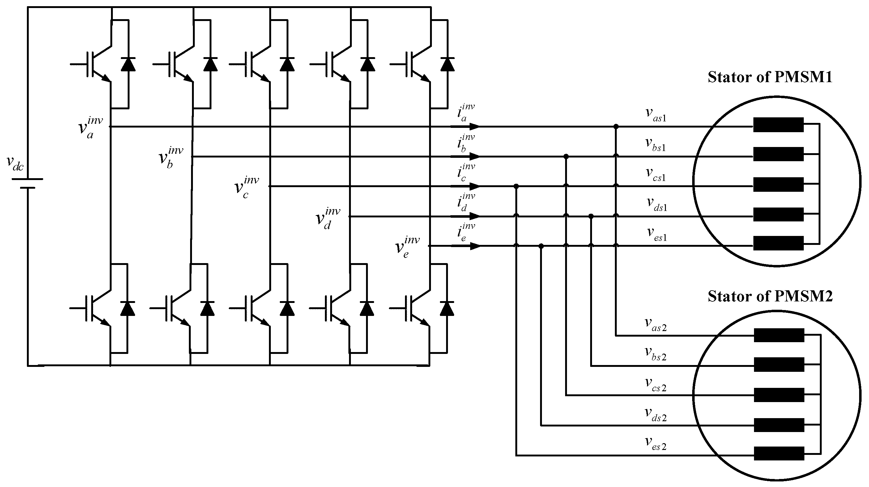
The two-machine drive system under consideration is shown in Figure 1. It consists of a five-leg inverter feeding two five-phase PMSMs. The five-phase PMSM has five-phase windings spatially shifted by 72 electrical degrees. In Figure 1 each stator is star-connected with isolated neutral point which eliminates the zero sequence voltages. It can be seen from Figure 1 that the phase transposition rules of parallel-connected two five-phase PMSMs system are as follows [17]: as1-as2, bs1-cs2, cs1-es2, ds1-bs2, es1-ds2. Where indices 1 and 2 identify the two machines as indicated in Figure 1. So, the relationships between voltages and currents are given as:
The main five dimensional systems can be decomposed into five dimensional uncoupled subsystems (d-q-x-y-0). Let the correlation between the original phase variables and the new (d-q-x-y-0) variables are given by , where C is the following invariant transformation matrix:
By applying the transformation matrix (2) on Equation (1), the voltage and current components of the five-phase VSI become:
From (3), it is evident that the inverter voltage d-q components can control the first machine (PMSM1), while the second machine (PMSM2) can be controlled separately using the inverter voltage x-y components.
The model of each five-phase PMSM is presented in a rotating d-q-x-y frame as:
where j = 1,2. vdj, vqj, vxj, vyj are the stator voltages in the d, q, x, y axes, respectively. idj, iqj, ixj, iyj are the stator currents in d, q, x, y axes, respectively. Ldj, Lqj, Llsj are inductances in the rotating frames. rsj is the stator resistance.
The torques equations for the first and the second machines are given by:
where pj are pole pairs, are the permanent magnet fluxes.
The proposed sensor-less control of the parallel-connected two five-phase permanent magnet synchronous machines is presented in Figure 2, where the two main parts EKF and SMC are considered. The EKF is designed to estimate the rotor position, speed and load torque of each machine by using a current observer. The feedback actual speed, estimated speed and load torques are the inputs of the speeds SMCs to determine the q1-y2 axes reference current components. The other current components are maintained to zero. The measured currents are processed in the current SMCs to obtain as outputs the dqxy axes reference voltages components. These reference voltages are transformed into the abcde frame and transformed again to αβxy frame to become input signals to the SVM blocks. The SVM transmits the signals to the inverter to drive the two five-phase PMSMs connected in parallel.
3. Sliding Mode Controller (SMC)
The design of a sliding mode controller requires mainly two stages. The first stage is choosing an appropriate sliding surface. The second stage is designing a control law, which will drive the state variables to the sliding surface and will keep them there.
3.1. Sliding Surfaces Choice
In order to prescribe the desired dynamic characteristics of the controlled system, the following general form of sliding surface can be adopted [35].
With: . : is a positive coefficient. r: is the relative degree, which is the number of times required to differentiate the surface before the input u {\display style u} appears explicitly.
3.2. Controller Design
In order to drive the state variables to the sliding surface, the following control law is defined as:
The equivalent control is capable to keep the state variables on the switching surface, once they reach it and to achieve the desired performance under nominal model. It is derived as the solution of the following equation:
The discontinuous control is needed to assure the convergence of the system states to sliding surfaces in finite time and it should be designed to eliminate the effect of any unpredictable perturbation. The discontinuous control input can be determined with the help of the following Lyapunov function candidate:
The stability is shown under two conditions as:
- The Lyapunov function V is positive definite.
- The derivative of the sliding function should be negative .
The so-called reaching stability condition is fulfilled using the following discontinuous control:
where G is a control gain.
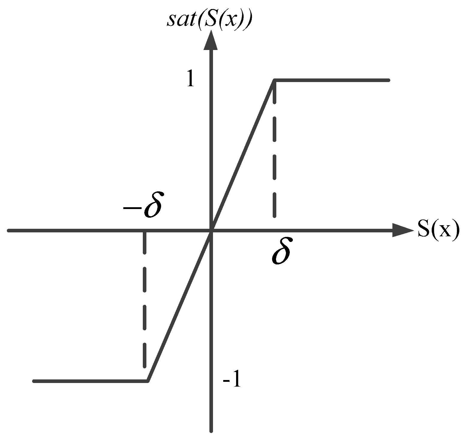
In order to reduce the chattering phenomenon, a saturation function instead of the switching one can be used. The saturation function depicted in Figure 3 is expressed as follows:
With is the boundary layer width.
4. Sliding Mode Control of the Five-Phase Two-Machine AC Drive System
4.1. Speeds SMC Design
The first task in the speeds SMC design process is to select suitable sliding surfaces . Since the relative degree is one, the following sliding surfaces are adopted:
By taking the derivative of sliding surfaces (12) with respect to time and using the machines motion equations, it yields:
where and are moment of inertia, damping coefficient and load torque of each machine. The currents controls and are defined by:
where:
During the convergence mode, the condition must be verified. By replacing (14) into (13), we get:
4.2. Currents SMC Design
The control objectives are to track the desired currents trajectories. So, the sliding surfaces can be calculated as follows:
The time derivative of (16) is:
Using (4), the Equation (17) can be rewritten as:
So, it is possible to choose the control laws for stator voltages as follows:
where:
During the convergence mode, the condition must be verified. By replacing (19) into (18), we get:
The control voltages given by (19) are transformed in abcde frame and then the inverter phase voltage references are calculated according to the following expression:
5. Space Vector Modulation Technique for Parallel Connected Multiphase AC Drive System
5.1. Five-Leg VSI Modeling
The five-leg inverter output phase-to-neutral voltages can be expressed as:
where denotes DC-link voltage and refer to switching functions.
The five-phase inverter has totally thirty-two space voltage vectors, thirty non-zero voltage vectors and two zero voltage vectors. These space vectors can be projected on α-β subspace as well as on x-y subspace as shown in Figure 4. Every plane is divided in ten sectors, each occupying a 36° angle around the origin by means of the following two space vectors [27]:
where .
From Figure 3 the space vectors are divided into three groups in accordance with their magnitudes: small, medium and large space vector groups. The magnitudes are identified with indices s, m and l and are given as: , and , respectively [27,35,36,37,38].It can be observed from Figure 3 that medium length space vectors of the α-β plane are mapped into medium length vectors in the x-y plane and large vectors of the α-β plane are mapped into small vectors in the x-y plane and vice-versa.
5.2. SVM Method for Five-Leg VSI
The reference voltage can be obtained by averaging a certain number of active space vectors for adequate time intervals, without saturating the VSI. Four active space vectors are required to reconstruct the reference voltage vector [27,36,37,38].
The dwell times for active space vectors T1m, T1l, T2m, T2l are:
where: is the switching period and is the voltage reference vector position.
The control strategy adopted herein is based on the approach proposed in [27,36]. Indeed, in the first switching period, the space vector modulator will apply α-β voltage reference. In the next switching period the space vector modulator will apply x-y voltage reference as shown in Figure 5. The selection of switching signals is depicted in Figure 6. So, two independent space vector modulators are further utilized to realize the required two voltage space vector references, with dwell times calculated independently in the two planes using (24).
6. Extended Kalman Filter Based Speed Estimator for Parallel Connected Two Motor Drivel
Normally, speed observers used for three-phase machines can be easily extended to multi-phase multi-machine drives. For each machine, the speed estimator requires only stator voltages and currents components. The SMC block diagram based on extended kalman filter of parallel-connected two five-phase machines drive system is shown in Figure 2. The main task of EKF is to find the best estimate of state variables and the unknown load torques since the knowledge of the load torque is necessary for each speed SMC implementation.
In the five-phase PMSM control case, d, q, x, y currents and voltages are measured and the Equation (4) is sampled to obtain a discrete state space representation to be used in the observer synthesis. Assuming that the sampling interval Te is very short compared to the system dynamics, the augmented discrete-time of each five-phase PMSM model is given as follows:
With:
where , and are the augmented state vector and input vector and output vector at the sampling instant k of machine j, respectively. and are discrete system matrix and discrete input matrix for each machine, respectively. and are the system noise and measurement noise, respectively.
The added white-noise vectors are Gaussian and uncorrelated from each other with zero mean and covariance Qj and Rj, respectively. The covariance matrices Qj and Rj of these noises are defined as:
In a first main stage the state xj(k+1) is predicted using discrete matrices and previous state. In a second main stage, the feedback correction weight matrix Kj (filter coefficients) is used to have an accurate prediction of the state xj(k+1/k). This is obtained by computing Kj depending not only on the error made but also with an adjustment using weight Pj (covariance state matrix). This allows estimating accurately xj with respect to Qj and Rj covariance matrices corresponding respectively to state noise and measurement noise levels [30]. Using Equation (25), the rotor speeds and load torques can be estimated by the extended Kalman filter algorithm described as follows:
- Sate prediction:
- Estimation of the matrix of the covariance error:
- Kalman coefficient update:
- State estimation:
- Covariance error matrix update:where is the system state, ujk is the system input vector, y is the system output vector, P, Q and R are the covariance matrices, C is the transformation matrix.
7. Numerical Simulation Results
In order to verify the applicability of the proposed control scheme for the two-machine drive system of Figure 2, the following simulations are performed using two identical 2-pole, 50 Hz five-phase PMSM. The parameters of each machine are listed in Table 1. The performance of the SMC controller is compared with that of the conventional controller. The tuning parameters for the PI controllers and SMC controllers are also given in Table 2. Many simulation tests are performed in order to verify the independence of the control of the two machines in sensor-less mode.
The behavior of the overall drive system is presented in Figure 7, Figure 8, Figure 9, Figure 10 and Figure 11 at different test conditions. Figure 7 shows then estimated speeds, currents and torques of the unloaded two machines for many different speeds references. At the beginning, the first machine is running at 100 rad/s, at t = 0.7 s it decelerated to −10 rad/s, after that, it is accelerated again to the speed 60 rad/sat t = 1.4 s. For the second machine the speed reference is set at 50 rad/s, 25 rad/s, 100 rad/s, −100 rad/s and 80 rad/s at t = 0 s, 0.4 s, 0.9 s, 1.2 s, 1.7 s, respectively. Effect of the speed rotation reversion of one machines on the other machine performance is investigated Figure 8. In this test, most of the time when one machine is rotating at +100 rad/s the other is running at the opposite speed.
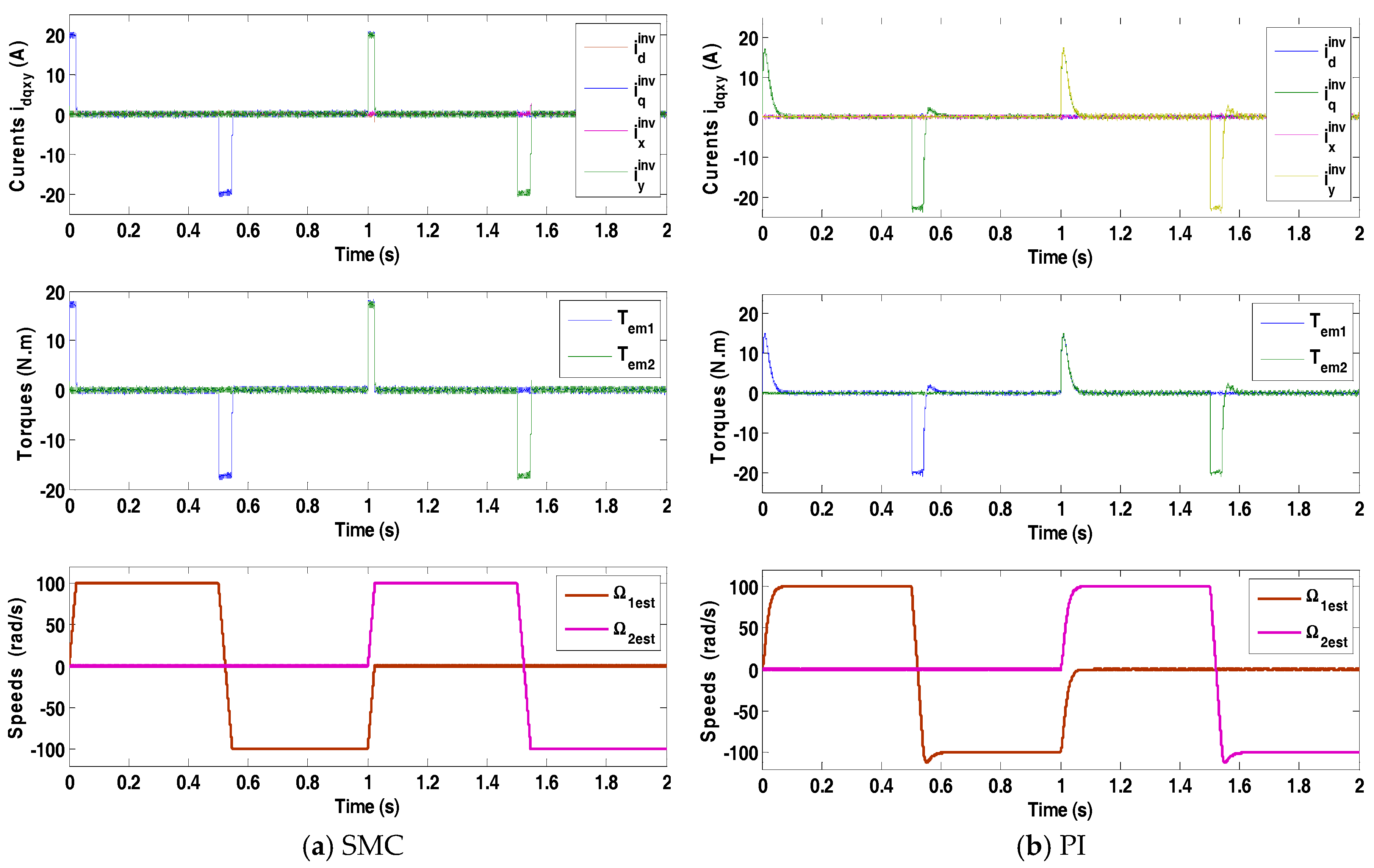
Some additional reversing tests are conducted next to further verify decoupling of the control of the two machines. Figure 9 displays results for the case when the speed Ω2 is kept at standstill, while Ω1 is reversed from: +100 to −100 rad/s at t = 0.5 s and returns to zero at t = 1 s. At the subsequent test, the speed Ω1 is held at zero, while Ω2 is reversed from 100 to −100 rad/s at 1.5 s.
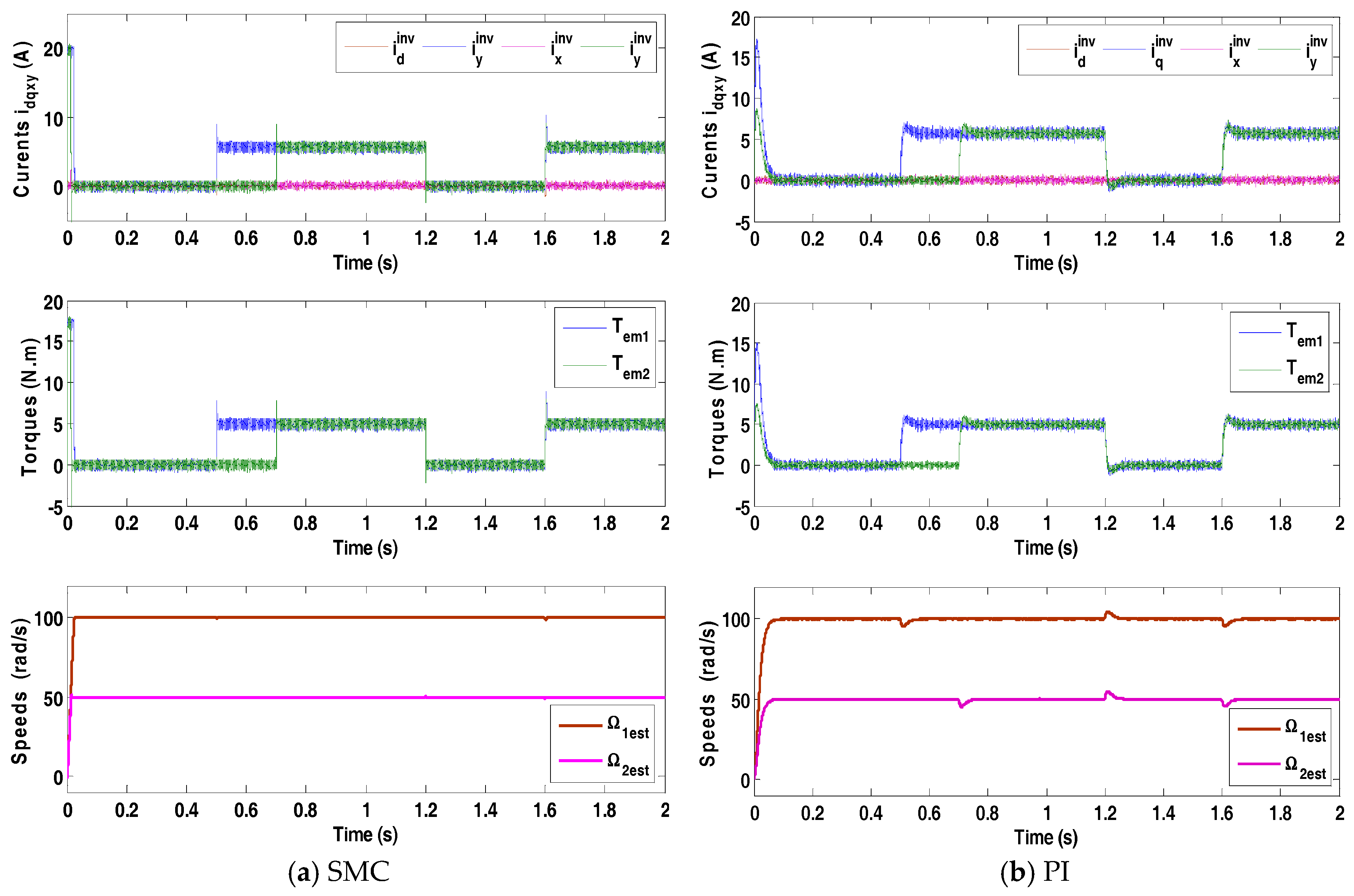
Figure 10 shows the speeds, torques and currents of the two-machine drive controlled by both PI and SMC controller in the presence of load torques variations. The reference of the first speed is fixed at 100 rad/s, while the speed reference of the second machine is fixed at 50 rad/s. Load torques are applied on the two machines at t = 0.5 s and t = 0.7 s, respectively.
It is clear from all estimated speeds characteristics that in every test the speed estimators provide accurate speed estimations. These results also prove that both speeds machines are independently controlled even in sensor-less mode. Indeed, the speed variation of the first machine in the two-machine drive system does not affect the behavior of the speed of the second machine even in reversal conditions.
The electromagnetic torque generated by each machine during the simulated speed step response is shown in Figure 7, Figure 8, Figure 9 and Figure 10. Note that the generated torques are directly proportional to the q-x axes currents and fully decoupled from d-y axes currents.
Comparison of results in Figure 7 shows once more that the control of the two machines is completely decoupled. There is hardly any evidence of torque disturbance of one machine during the reversal of the other one. Furthermore, the direct axis currents responses remain completely unaffected during these transients.
As shown from Figure 8, the starting and reversing transients of one machine do not have any tangible consequence on the operation of the second machine. The decoupled control is preserved and the characteristics of both machines are unaffected.
Figure 9 illustrates results for the case when the speed of one machine is kept at zero, while the second is reversed. Speed of one machine and its electromagnetic torque remain completely undisturbed during the reversion of the other machine, indicating a complete decoupling of the control.
Figure 10 shows inverter current characteristic, motor torques and estimated speed of motors at different loading conditions for parallel-connected two five-phase machines drive system. It is clear from Figure 10 that when one machine is loaded or unloaded, the second machine performance is unaffected; which proves once again that both motors connected in parallel are totally decoupled. In case of sliding mode control, no variation whatsoever can be observed in the speeds responses of the both machines during these transients.
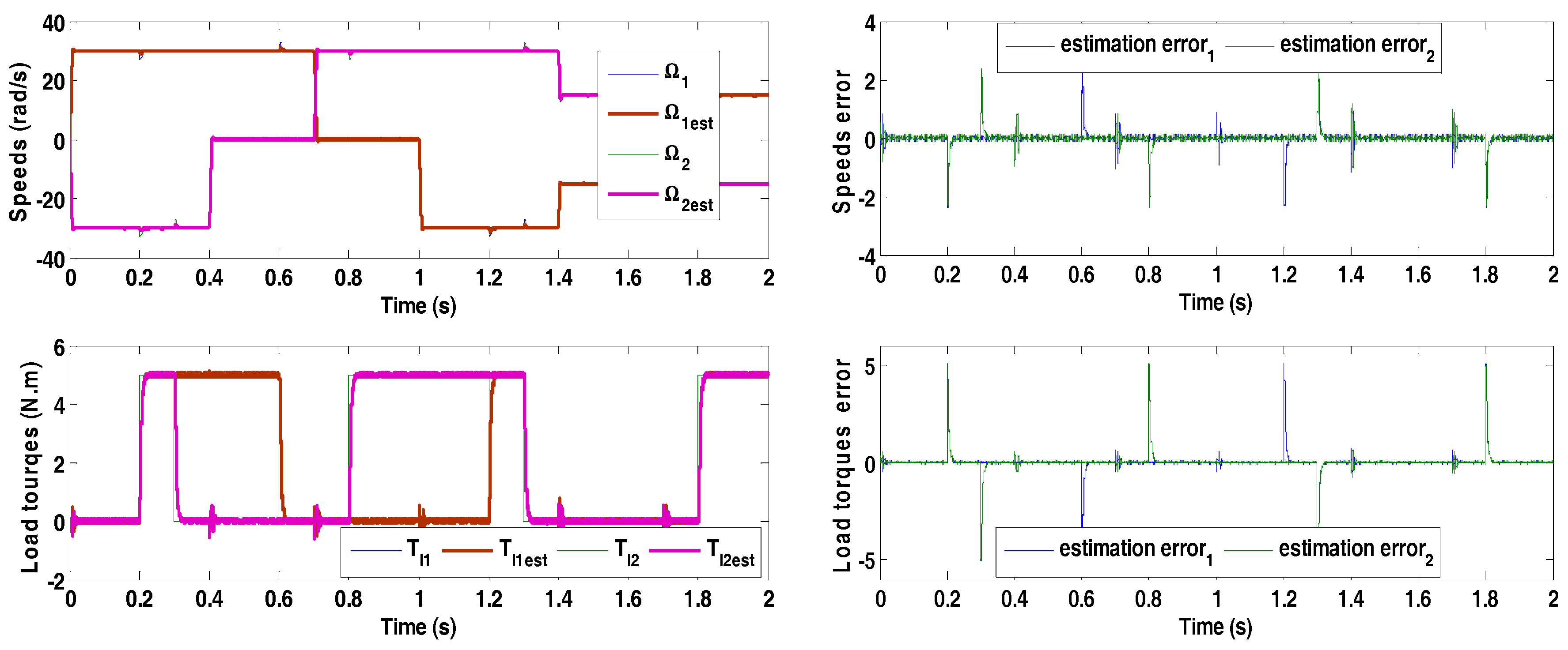
The estimated and actual values of speeds and load torques as well as their estimations errors are reported in Figure 11. The EKF algorithms give accurate and fast speeds estimations over entire speed range including low speed and standstill operations with low speed errors, even in transients. Furthermore, the estimated values of loads torques are very close to their applied ones. Consequently, the load torque estimation errors are almost zeros; this reflects the stability of EKF during load torques variations. These results confirm that the extended Kalman filter is very suitable for two-machine drive system.
It is worth to notice that there is no impact on the speed and electromagnetic torque of one machine when the speed or the load of the other machine in parallel-connected system changes. Thus, through proper phase transformation rules, the decoupled control of two five-phase PMSMs connected in parallel can be achieved with a single supply from a five-phase voltage source inverter. Furthermore, measured and estimated speeds are in excellent agreement in both steady state and transient operations.
Figure 7, Figure 8, Figure 9 and Figure 10 illustrate the behavior of the dq-axes and xy-axes inverter currents for both controllers. In case of the PI controller, the stator currents and peak above 17 A, then decay exponentially to the steady-state while the currents and are maintained at zero as illustrated in Figure 7b, Figure 8b, Figure 9b and Figure 10b. Figure 7a, Figure 8a and Figure 9a show currents in case of sliding mode control. In contrast, the and currents peak slightly above 20 A and continue on this value, until the speed reaches its reference value, this leads to a short settling time, as shown in Figure 7a, Figure 8a, Figure 9a and Figure 10a.
Figure 7, Figure 8 and Figure 9 show the behavior of the two-machine drive under different speeds step variations and without load torque. In Figure 7b, Figure 8b and Figure 9b, the system comportment using PI controller exhibits the expected step response characteristics of a second order system. The response has a short rise time, an overshoot of approximately 18% during reverse modes and settling times close to 0.075 s. Figure 7a, Figure 8a and Figure 9a show comparable dynamic behavior using SMC. However, it is clear from these figures that the system reaches steady-state at 0.028 s without overshoot.
From Figure 10b and by analyzing the transient of two-machine drive controlled by PI controller, it is easy to observe speeds drops taken place at the moments of loads changes. These speed drops are compensated by the PI controller after a necessary recovery time. Figure 10a shows the drive responses in the same load conditions with PI control. At the moments of load variations, the SMCs keep the speeds close to their references without overshoots and without drops. Therefore, the SMC can be considered as more robust under loads variations.
A general comparison between SMC and PI is given in Table 3. Compared to PI controller, SMC shows superiority in terms of settling time and overshoot. However, it needs more energy in starting transient then that needed by the conventional controller.
8. Conclusions
In this paper, sensor-less non-linear sliding mode control based on the Lyapunov theory of parallel-connected two five-phase PMSMs drive fed by a single inverter has been developed in order to make the system asymptotically stable. In the proposed control scheme, the Extended Kalman Filter is used for rotor speeds, positions and load torques estimations, while a sliding mode controller is used for speeds and currents control. The sliding mode control has several advantages such as, robustness, high precision, stability and simplicity, very low Settling time. The added value of EKF based sensor-less control is the improvement in system dynamics through the accuracy in speeds, rotor positions and load torques estimations. The effectiveness of the control approach has also been verified through extensive computer simulations and compared with PI controller. The response has a short rise time, an overshoot during reverse modes in PI controller and settling times close to 0.075 s. However, the speed response obtained by SMC is without overshoot and follows its reference and settling times close to 0.028 s. The results also show that the torque obtained by the PI control decreases progressively, while the torque obtained by the SMC is maintained longer at its maximum value, until the speed reaches its reference value. Speeds drops taken place at the moments of loads changes in PI controller. The SMC keep the speeds close to their references without overshoots and without drops. Therefore, the SMC can be considered as more robust under loads variations. SMC shows better speed tracking performance at both dynamic and steady state than conventional PI controller in the situation reverse modes and load torque variations. Thus, simulation results have verified the proposed whole system has great robust to external disturbances. The simulation of the two-machine drive under various test conditions confirmed that the control of the parallel-connected two five-phase machines is truly decoupled even in sensor-less mode. These results affirm also the ability of the observer to guarantee good estimations in steady state and transients as well. Simulation results point out also that using sliding mode control the dynamic performance of the two-machine drive is further improved compared with the conventional PI controller.
Acknowledgments
No source of funding for this research investigation.
Author Contributions
All authors contributed equally for the final decimation of the research investigation as a full article.
Conflicts of Interest
The authors declare no conflict of interest.
References
- Navid, R.A. Sliding-mode control of a six-phase series/parallel connected two induction motors drive. ISA Trans. 2014, 53, 1847–1856. [Google Scholar]
- Chen, H.H.; Chong, X.S. Current control for single-inverter-fed series-connected five-phase PMSMS. In Proceedings of the IEEE International Symposium on Industrial Electronics, Taipei, Taiwan, 28–31 May 2013; pp. 1–6. [Google Scholar]
- Liliang, G.; John, E.F. A space vector switching strategy for three-level five-phase inverter drives. IEEE Trans. Ind. Electron. 2010, 57, 2332–2343. [Google Scholar] [CrossRef]
- Sneessens, C.; Labbe, T.; Baudart, F.; Matagne, E. Position sensorless control for five-phase permanent-magnet synchronous motors. In Proceedings of the International Conference on Advanced Intelligent Mechatronics, Besançon, France, 8–11 July 2014; pp. 794–799. [Google Scholar]
- Wang, Z.; Wang, X.J.C.; Cheng, M.; Hu, Y. Direct torque control of T-NPC inverters fed double-stator-winding PMSM drives with SVM. IEEE Trans. Power Electron. 2018, 33, 1541–1553. [Google Scholar] [CrossRef]
- Wang, X.; Wang, Z.; Cheng, M.; Hu, Y. Remedial strategies of T-NPC three-level asymmetric six-phase PMSM drives based on SVM-DTC. IEEE Trans. Ind. Electron. 2017, 64, 6841–6853. [Google Scholar] [CrossRef]
- Lei, Y.; Ming-liang, C.; Jian-qing, S.; Fei, X. Current Harmonics Elimination Control Method for Six-Phase PM Synchronous Motor Drives. ISA Trans. 2015, 59, 443–449. [Google Scholar]
- Leila, P.; Hamid, A.T. Sensorless Direct Torque Control of Five-Phase Interior Permanent-Magnet Motor Drives. IEEE Trans. Ind. Appl. 2007, 43, 952–959. [Google Scholar]
- Siavash, S.; Lusu, G.; Hamid, A.T.; Leila, P. Wide Operational Speed Range of Five-Phase Permanent Magnet Machines by Using Different Stator Winding Configurations. IEEE Trans. Ind. Electron. 2012, 59, 2621–2631. [Google Scholar]
- Hosseyni, A.; Ramzi, T.; Faouzi, M.M.; Atif, I.; Rashid, A. Sensorless Sliding Mode Observer for a Five-Phase Permanent Magnet Synchronous Motor Drive. ISA Trans. 2015, 58, 462–473. [Google Scholar] [CrossRef] [PubMed]
- Ahmad, A.A.; Dahaman, I.; Pais, S.; Shahid, I. Speed-Sensorless Control of Parallel-Connected PMSM Fed By A Single Inverter Using MRAS. In Proceedings of the IEEE International Power Engineering and Optimization Conference, Melaka, Malaysia, 6–7 June 2012; pp. 35–39. [Google Scholar]
- Zhang, H.; Luo, S.; Yu, Y.; Liu, L. Study On Series Control Method For Dual Three-Phase PMSM Based On Space Vector Pulse Width Modulation. Int. J. Control Autom. 2015, 8, 197–210. [Google Scholar] [CrossRef]
- Martin, J.; Emil, L.; Slobodan, N.V. Independent Control of Two Five-Phase Induction Machines Connected In Parallel To A Single Inverter Supply. In Proceedings of the IEEE Industrial Electronics Conference, Paris, France, 6–10 November 2006; pp. 1257–1262. [Google Scholar]
- Levi, E.; Jones, M.; Vukosavic, S.N.; Iqbal, A.; Toliyat, H.A. Modeling, control, and experimental investigation of a five-phase series-connected two-motor drive with single inverter supply. IEEE Trans. Ind. Electron. 2007, 54, 1504–1516. [Google Scholar] [CrossRef]
- Levi, E.; Jones, M.; Slobodan, N.V.; Hamid, A.T. Steady-State Modeling of Series-Connected Five-Phase And Six-Phase Two-Motor Drives. IEEE Trans. Ind. Appl. 2008, 44, 1559–1568. [Google Scholar] [CrossRef]
- Mekri, F.; Charpentier, J.F.; Semail, E. An Efficient Control of A Series Connected Two-Synchronous Motor 5-Phase with Non-Sinusoidal EMF Supplied By A Single 5-Leg VSI: Experimental And Theoretical Investigations. Electr. Power Syst. Res. 2012, 92, 11–19. [Google Scholar] [CrossRef] [Green Version]
- Jones, M.; Vukosavic, S.N.; Levi, E. Parallel-Connected Multiphase Multidrive Systems with Single Inverter Supply. IEEE Trans. Ind. Electron. 2019, 56, 2047–2057. [Google Scholar] [CrossRef]
- Zhang, X.; Lizhi, S.; Zhao, K.; Sun, L. Nonlinear Speed Control for PMSM System Using Sliding-Mode Control and Disturbance Compensation Techniques. IEEE Trans. Power Electron. 2013, 28, 1358–1365. [Google Scholar] [CrossRef]
- Fatemi, F.S.M.J.R.; Navid, R.A.; Jafar, S.; Saeed, A. Speed Sensorless Control of a Six-Phase Induction Motor Drive Using Backstepping Control. IET Power Electron. 2014, 7, 114–123. [Google Scholar] [CrossRef]
- Anissa, H.; Ramzi, T.; Atif, I.; Med, F.M. Backstepping Control for a Five-Phase Permanent Magnet Synchronous Motor Drive. Int. J. Power Electron. Drive Syst. 2015, 6, 842–852. [Google Scholar]
- Ahmed, M.; Karim, F.M.; Abdelkader, M.; Abdelber, B. Input Output Linearization And Sliding Mode Control of a Permanent Magnet Synchronous Machine Fed by a Three Levels Inverter. J. Electr. Eng. 2006, 57, 205–210. [Google Scholar]
- Le-Bao, L.; Ling-Ling, S.; Sheng-Zhou, Z.; Qing-Quan, Y. PMSM Speed Tracking And Synchronization of Multiple Motors Using Ring Coupling Control and Adaptive Sliding Mode Control. ISA Trans. 2015, 58, 635–649. [Google Scholar]
- Lin, S.F.J.; Hung, Y.C.; Tsai, M.T. Fault-Tolerant Control for Six-Phase PMSM Drive System via Intelligent Complementary Sliding Mode Control Using TSKFNN-AMF. IEEE Trans. Ind. Electron. 2013, 60, 5747–5762. [Google Scholar] [CrossRef]
- Chen, S.; Luo, Y.; Pi, Y.G. PMSM Sensorless Control with Separate Control Strategies and Smooth Switch from Low Speed to High Speed. ISA Trans. 2015, 58, 650–658. [Google Scholar] [CrossRef] [PubMed]
- Dujic, D.; Jones, M.; Levi, E.; Prieto, J.; Barrero, F. Switching Ripple Characteristics of Space Vector PWM Schemes for Five-Phase Two-Level Voltage Source Inverters—Part 1: Flux Harmonic Distortion Factors. IEEE Trans. Ind. Electron. 2011, 58, 2789–2798. [Google Scholar] [CrossRef]
- Iqbal, A.; Levi, E. Space Vector Modulation Schemes for a Five-Phase Voltage Source Inverter. In Proceedings of the European Conference on Power Electronics and Applications, Dresden, Germany, 11–14 September 2005; pp. 1–12. [Google Scholar]
- Dujic, D.; Grandi, G.; Jones, M.; Levi, E. A Space Vector PWM Scheme for Multi Frequency Output Voltage Generation with Multiphase Voltage-Source Inverters. IEEE Trans. Ind. Electron. 2008, 55, 1943–1955. [Google Scholar] [CrossRef]
- Quang, N.K.; Hieu, N.T.; Ha, Q.P. FPGA-Based Sensorless PMSM Speed Control Using Reduced-Order Extended Kalman Filters. IEEE Trans. Ind. Electron. 2014, 12, 6574–6582. [Google Scholar] [CrossRef]
- Zhuang, X.; Rahman, M.F. Comparison of a Sliding Observer and a Kalman Filter for Direct-Torque-Controlled IPM Synchronous Motor Drives. IEEE Trans. Ind. Electron. 2012, 59, 4179–4188. [Google Scholar]
- Dong, X.; Zhang, S.; Liu, J. Very-Low Speed Control of PMSM Based on EKF Estimation with Closed Loop Optimized Parameters. ISA Trans. 2013, 52, 835–843. [Google Scholar]
- Abbas, N.K.; Jafar, S. MTPA Control of Mechanical Sensorless IPMSM Based on Adaptive Nonlinear Control. ISA Trans. 2016, 61, 348–356. [Google Scholar]
- Khan, M.R.; Iqbal, A. MRAS Based Sensorless Control of a Series-Connected Five-Phase Two-Motor Drive System. J. Electr. Eng. Technol. 2008, 3, 224–234. [Google Scholar] [CrossRef]
- Khan, M.R.; Iqbal, A. Extended Kalman Filter Based Speeds Estimation of Series-Connected Five-Phase Two-Motor Drive System. Simul. Model. Pract. Theory 2009, 17, 1346–1360. [Google Scholar] [CrossRef]
- Ali, W.H.; Gowda, M.; Cofie, P.; Fuller, J. Design of a Speed Controller Using Extended Kalman Filter for PMSM. In Proceedings of the IEEE 57th International Midwest Symposium on Circuits and Systems, College Station, TX, USA, 8–11 July 2014; pp. 1101–1104. [Google Scholar]
- Slotine, J.J. Applied Nonlinear Control; Tice Hall: Englewood Cliffs, NJ, USA, 1991. [Google Scholar]
- Iqbal, A.; Levi, E. Space Vector PWM for a Five-Phase VSI Supplying Two Five-Phase Series-Connected Machines. In Proceedings of the 12th International Power Electronics and Motion Control Conference, Portoroz, Slovenia, 30 August–1 September 2006; pp. 222–227. [Google Scholar]
- Dujic, D.; Jones, M.; Levi, E. Generalised Space Vector PWM for Sinusoidal Output Voltage Generation with Multiphase Voltage Source Inverters. Int. J. Ind. Electron. Drives 2009, 1, 1–13. [Google Scholar] [CrossRef]
- Jones, M.; Dordevic, O.; Bodo, N.; Levi, E. PWM Algorithms for Multilevel Inverter Supplied Multiphase Variable-Speed Drives. Electronics 2012, 16, 22–31. [Google Scholar] [CrossRef]
Figure 1.
A parallel connected five-phase two-motor drive.

Figure 2.
Sensor-less SMC of parallel-connected two five-phase PMSMs drive system.
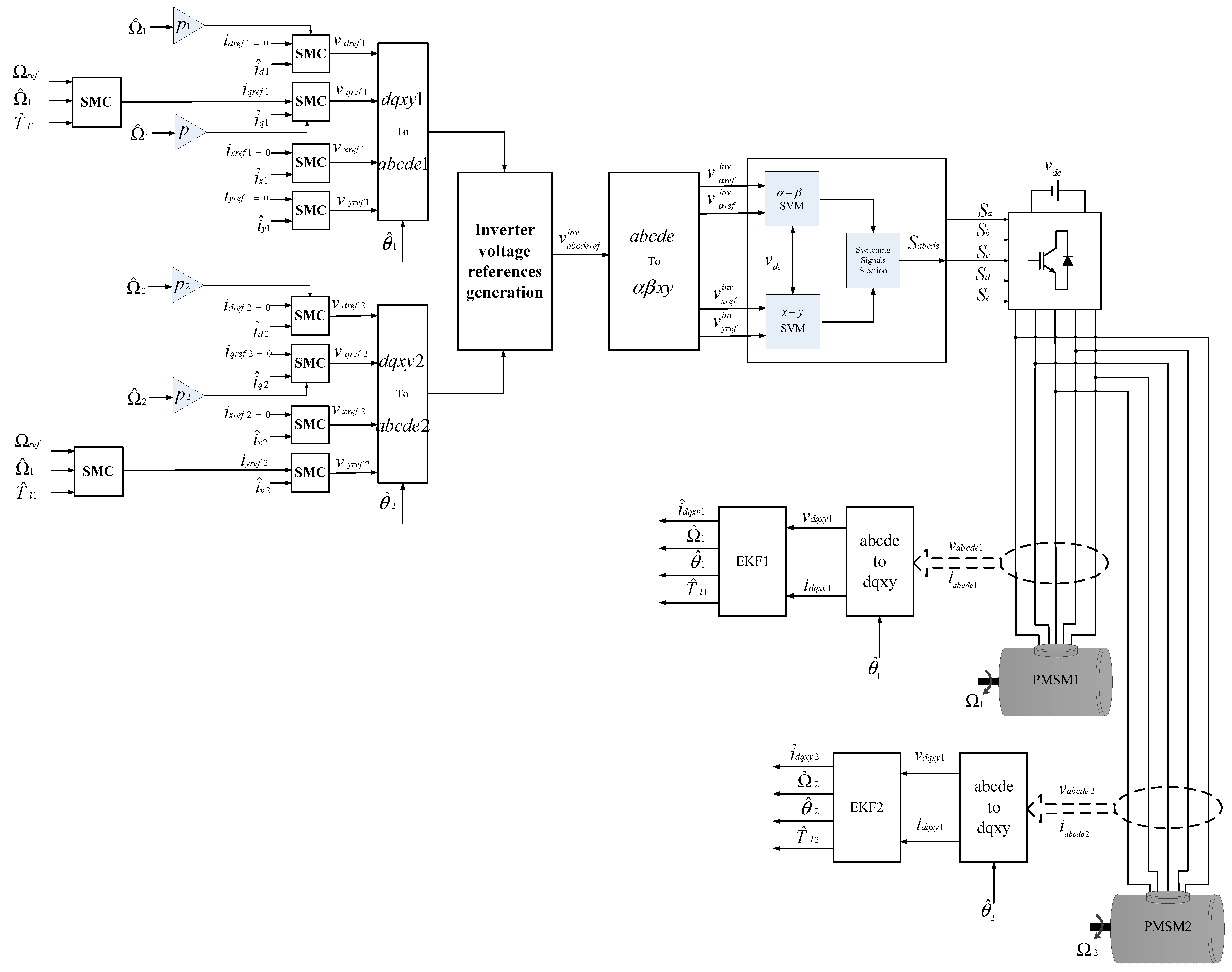
Figure 3.
Saturation function.

Figure 4.
Space vectors of a five-phase inverter in two 2-D subspaces.
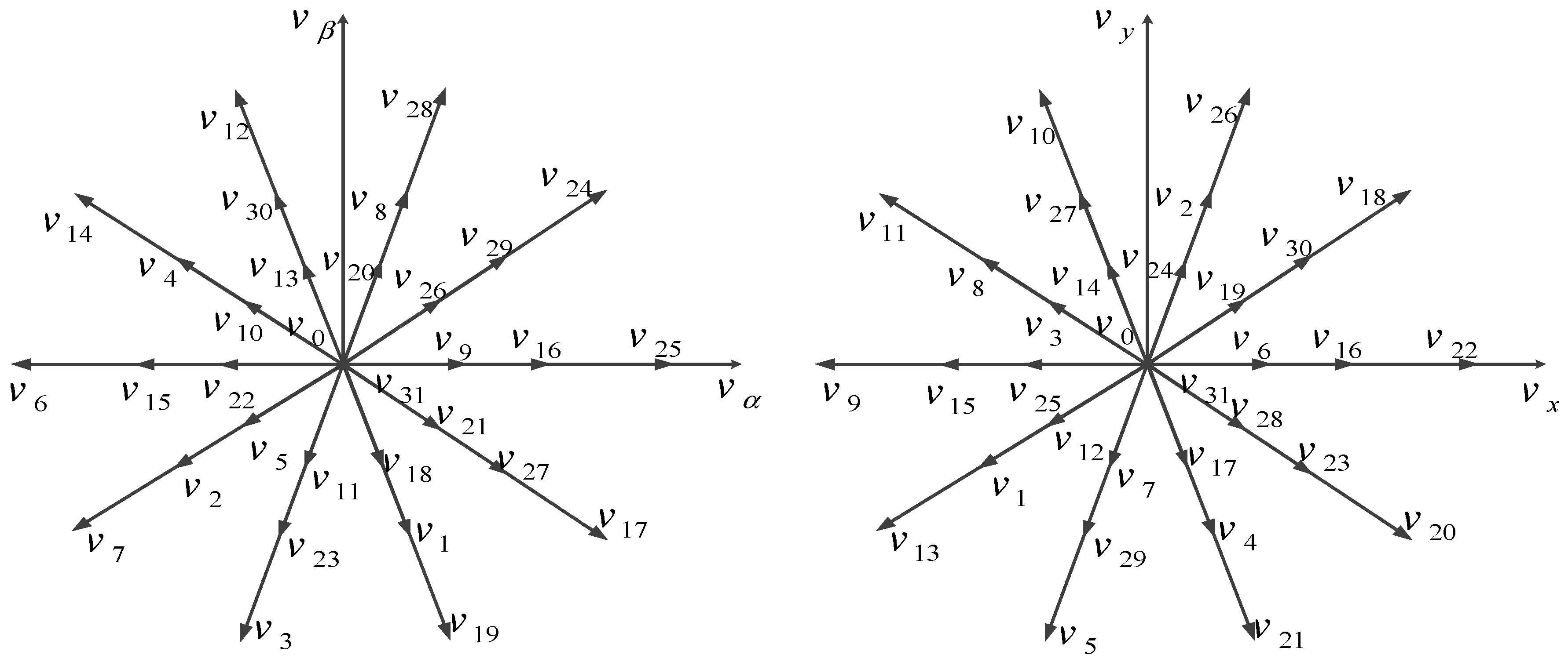
Figure 5.
Steps of SVM technique for parallel connected two-machine drive.
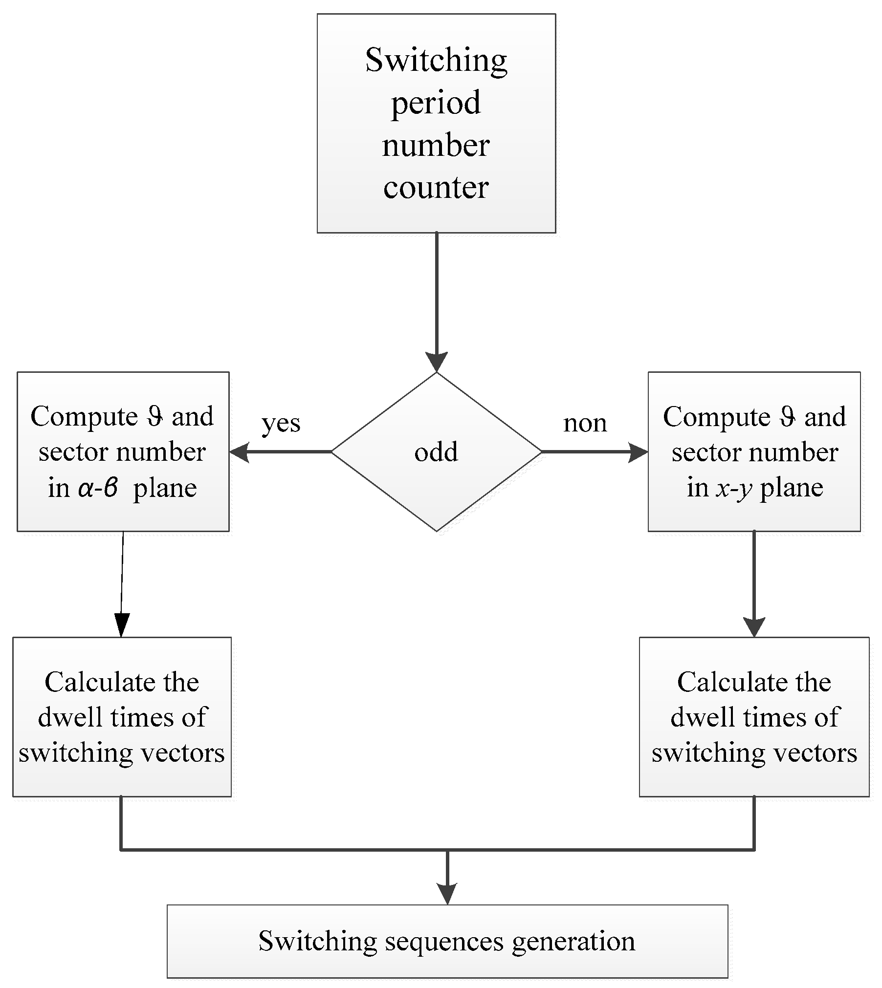
Figure 6.
Switching pattern obtained with SVM.
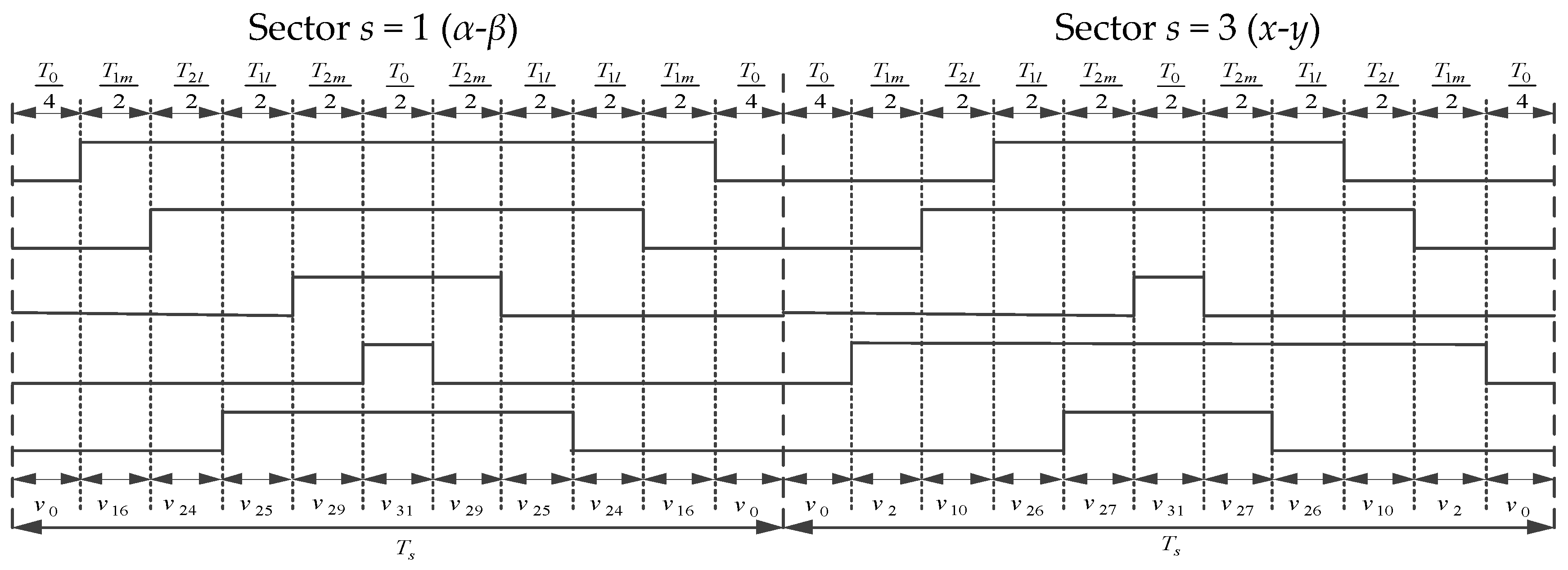
Figure 7.
Dynamic responses of parallel-connected two five-phase PMSMs system at different reference speeds values.
Figure 7.
Dynamic responses of parallel-connected two five-phase PMSMs system at different reference speeds values.
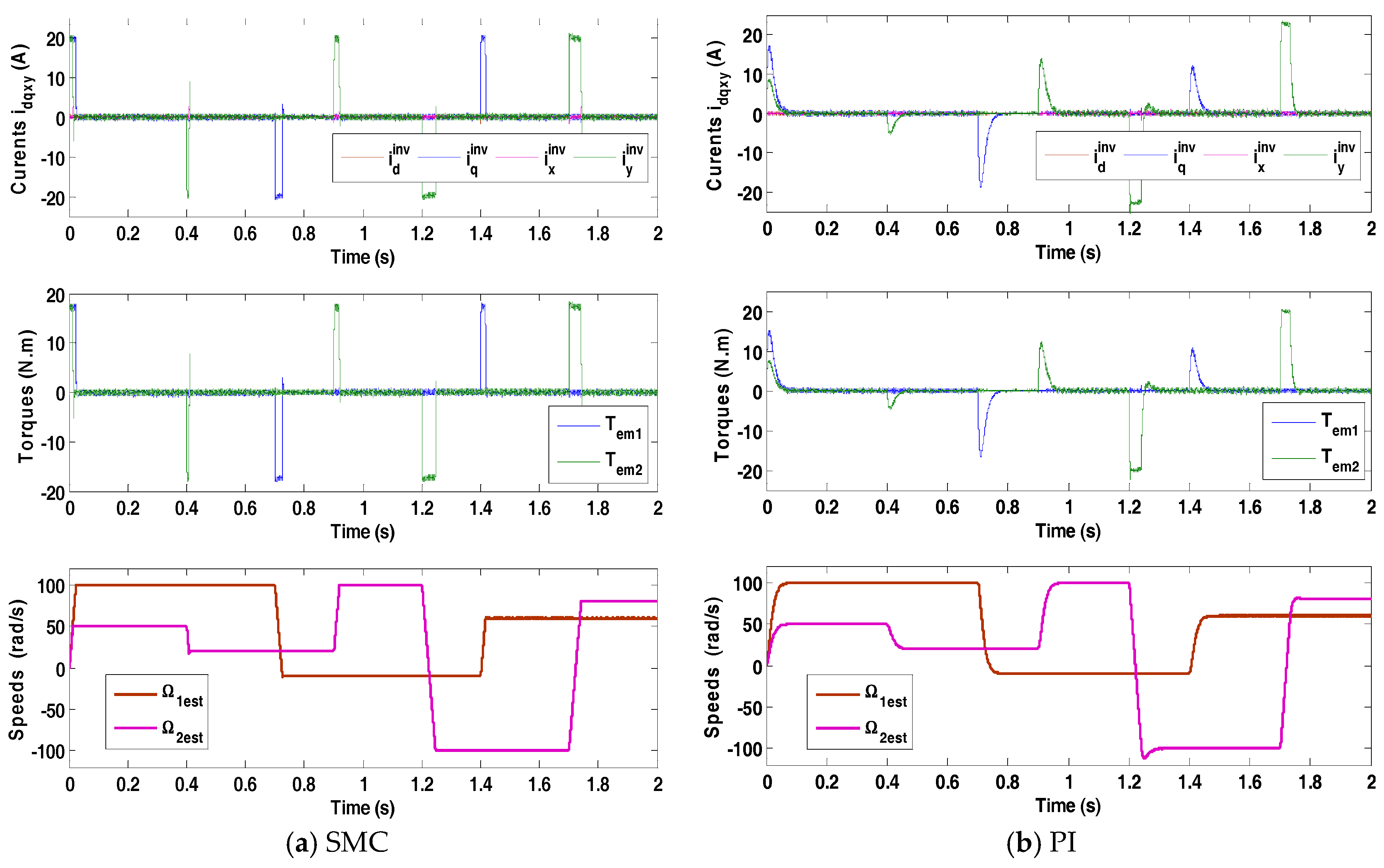
Figure 8.
Dynamic responses of parallel-connected two five-phase PMSMs system: when the two motors are operating in the opposite directions.
Figure 8.
Dynamic responses of parallel-connected two five-phase PMSMs system: when the two motors are operating in the opposite directions.
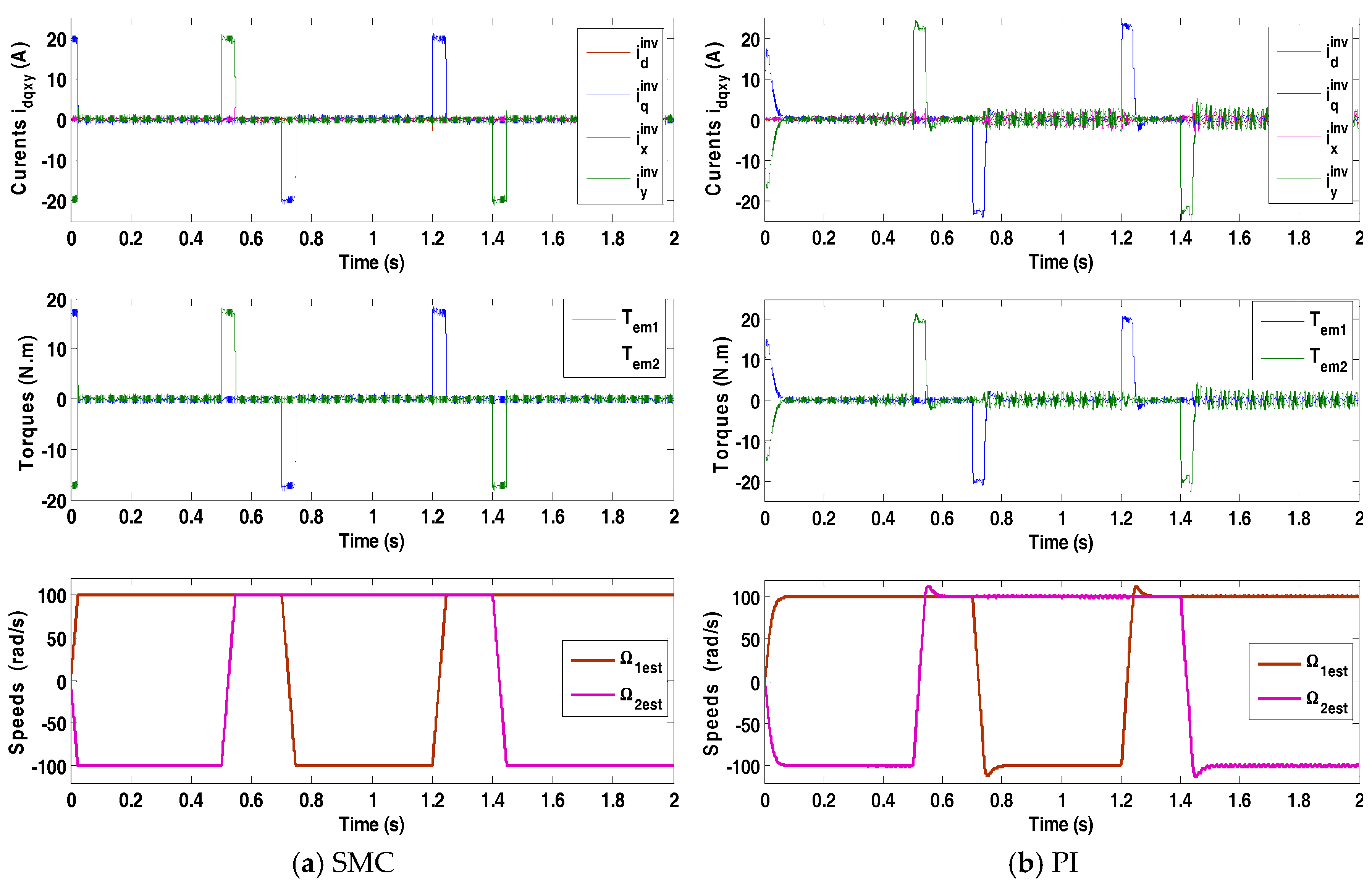
Figure 9.
Dynamic responses of parallel-connected two five-phase PMSMs system: when one machine is at standstill and the other is still running.
Figure 9.
Dynamic responses of parallel-connected two five-phase PMSMs system: when one machine is at standstill and the other is still running.

Figure 10.
Dynamic responses of parallel-connected two five-phase PMSMs system at different loading conditions.
Figure 10.
Dynamic responses of parallel-connected two five-phase PMSMs system at different loading conditions.

Figure 11.
Actual and estimated speeds and load torques and their corresponding estimation errors (SMC case).
Figure 11.
Actual and estimated speeds and load torques and their corresponding estimation errors (SMC case).


Table 1.
Five-phase PMSM parameters.
| pj | Ldj | Lqj | Llsj | Jj | rsj | fj | |
|---|---|---|---|---|---|---|---|
| 2 | 8.5 mH | 8 mH | 0.2 mH | 0.175 Wb | 0.004 kg m2 | 1 Ω | 0 |
Table 2.
PI and SMC parameters.
| Speed Controller | isd Controller | isq Controller | isx Controller | isy Controller | |
|---|---|---|---|---|---|
| PI | kp = 0.8 | kp = 33 | kp = 33 | kp = 33 | kp = 33 |
| ki = 40 | ki = 32,000 | ki = 32,000 | ki = 32,000 | ki = 32,000 | |
| SMC | GΩj = 5 | Gidj = 4000 | Giqj = 7000 | Gixj = 4000 | Giyj = 7000 |
Table 3.
Comparison between SMC and PI.
| Comparison Criterion | SMC | PI |
|---|---|---|
| Settling time (s) | 0.028 | 0.075 |
| Recovery time (at abrupt load) (s) | 0.0045 | 0.05 |
| Overshoot in reversal mode (%) | 0 | 18% |
| Starting current (A) | 20 | 17 |
| Starting torque (Nm) | 18 | 15 |
| Speeds drops (%) | 0 | 5 |
© 2018 by the authors. Licensee MDPI, Basel, Switzerland. This article is an open access article distributed under the terms and conditions of the Creative Commons Attribution (CC BY) license (http://creativecommons.org/licenses/by/4.0/).
Share and Cite
MDPI and ACS Style
Kamel, T.; Abdelkader, D.; Said, B.; Padmanaban, S.; Iqbal, A. Extended Kalman Filter Based Sliding Mode Control of Parallel-Connected Two Five-Phase PMSM Drive System. Electronics 2018, 7, 14. https://doi.org/10.3390/electronics7020014
AMA Style
Kamel T, Abdelkader D, Said B, Padmanaban S, Iqbal A. Extended Kalman Filter Based Sliding Mode Control of Parallel-Connected Two Five-Phase PMSM Drive System. Electronics. 2018; 7(2):14. https://doi.org/10.3390/electronics7020014
Chicago/Turabian StyleKamel, Tounsi, Djahbar Abdelkader, Barkat Said, Sanjeevikumar Padmanaban, and Atif Iqbal. 2018. "Extended Kalman Filter Based Sliding Mode Control of Parallel-Connected Two Five-Phase PMSM Drive System" Electronics 7, no. 2: 14. https://doi.org/10.3390/electronics7020014
Note that from the first issue of 2016, this journal uses article numbers instead of page numbers. See further details here.