1. Introduction
Three Dimensional MIMO (3D-MIMO) is a type of Massive MIMO Technology which has the ability to move the beam horizontally as well as vertically. In recent years, with the widespread use of smartphones such as mobile phones and tablets, the volume of mobile data services has exploded, and existing wireless communication systems can no longer meet such huge business demands. Therefore, academia and industry have successfully conducted research on 5G mobile communication. Massive MIMO technology is one of the candidate key technologies for 5G. Compared with the existing 4G technologies, it can significantly improve the spectrum efficiency and energy efficiency of the communication system and has become a research hotspot at home and abroad [
1]. The combination of Massive Multi-user MIMO (MU-MIMO) systems can further utilize spatial freedom to significantly increase system throughput and spectrum efficiency [
2]. As a key technology of the MU-MIMO system, precoding can effectively suppress multi-user interference and improve the Signal-to-Noise Ratio (SNR) [
3]. However, to make full use of the role of precoding, the transmitter must obtain enough channel state information (CSI). For Time Division Duplexing (TDD) systems, CSI can be obtained through the reciprocity of uplink and downlink channels, but susceptible to pilot contamination [
4]. In a Frequency Division Duplex (FDD) system, CSI acquisition relies on a feedback link. In an actual system, the feedback link bandwidth is limited. Therefore, in FDD massive MU-MIMO systems, codebook-based Multi-user precoding scheme, in which codebook design and multi-user scheduling strategy, are particularly important.
In the traditional MIMO system, the base station adopts a uniform linear array with a fixed down-tilt angle, and the wireless channel exhibits two-dimensional (2D) characteristics, that is, only the horizontal dimension freedom is available, which is called 2D-MIMO. However, in massive MIMO systems, base stations usually use 2D or 3D array antennas, which form the so-called 3D-MIMO technology [
5,
6]. Due to the expansion of the antenna array structure, 3D-MIMO channels exhibit different spatial correlations [
7,
8], and they also include horizontal and vertical dimension channel information. Therefore, 3D beamforming techniques can accurately align different levels of the dimensional sum. Thus, reduce the interference between users.
This paper proposes a novel codebook design for 3D based MIMO system in heterogeneous network scenarios. According to the quantization error and statistical characteristics of the random distribution of the system, the influence of feedback overhead and base station density on system performance is analyzed using stochastic geometry. An improved 3D precoding scheme based on horizontal emission angle and vertical down-tilt is proposed. Through simulation analysis, the influence of feedback overhead on system throughput is compared, and the effects of traditional DFT precoding methods in 2D and 3D environments and improved 3D precoding schemes on system BER and throughput are compared. The simulation results show that the feedback overhead will reduce the system throughput and improve the system BER, while the improved precoding scheme due to the joint consideration of the horizontal emission angle and vertical down-tilt, thus effectively improving the system throughput and reducing the system BER, optimized system performance.
The rest of the paper is organized as follows.
Section 2 discusses the literature review.
Section 3 explains the system model.
Section 4 provides system performance analysis based on random geometric finite feedback.
Section 5 provides the improved 3D codebook design concepts.
Section 6 gives the simulations results and analysis while
Section 7 concludes the paper.
2. Related Work
Massive multiple-input multiple-output (MIMO) has become one of the most important technologies in wireless communication in the future [
9]. Three-dimensional MIMO (3D-MIMO) is one of the main application scenarios of massive MIMO. Due to the limited space of these base station (BS), 3D-MIMO can use the Uniform Planar Arrays (UPA) to place hundreds of antennas in a relatively small space. In addition, 3D-MIMO can control the beam in the horizontal and vertical directions of the signal. Reasonable transmission and reception techniques can reduce multi-user interference and greatly improve system performance [
10]. As the urban environment becomes more and more modern, the number of users in the community is increasing, and users are more and more dispersed in three-dimensional space. Since traditional base station transmitter beam can only be adjusted in the horizontal dimension, the vertical dimension is a fixed down dip for each user. However, the actual signal propagation channel has three-dimensional space characteristics, which can lead to serious inter-cell interference among the users of the cell, which greatly reduces the cell edge user throughput [
11]. The 3D-MIMO precoding technique can divide each vertical antenna element into a plurality of elements without changing the size of the existing antenna so that the vertical dimension has a distinguishable pitch angle, which performed in the horizontal and vertical dimensions. Joint beamforming design can make full use of three-dimensional space freedom, bring more power interference control capabilities, and improve system performance [
12]. At present, the research on the codebook design scheme for 3D precoding has achieved certain results, but most studies are based on the discrete Fourier transform (DFT) codebook [
13,
14]. However, since the DFT codebook has strong beam directivity and uniform distribution, it is suitable for horizontal dimension codebooks using a uniform linear array (ULA). However, due to the narrow and nonuniform distribution of the up-and-down inclination of the vertical direction, it is not applicable to the vertical dimension codebook using the uniform planar array (UPA) [
15]. The improved codebook study still uses the DFT codebook in the horizontal direction and uses the distribution characteristics of the vertical down tilt in the vertical direction. Several discrete quantization angles are extracted in the vertical down-tilt angle interval and constructed by the corresponding beam steering vectors. The vertical codebook [
16], or the codeword phase determined by the specific position of the antenna array element, is used to construct the vertical codebook [
17], or on the basis of analyzing the correlation of the 3D-MIMO channel, for the transmit correlation and receive correlation matrix in the decomposition of the horizontal and vertical dimensions, a new 3D codebook is constructed combining the DFT codebook and the Grassmannian codebook in the 2D-MIMO channel [
18]. However, these codebook designs do not consider the launch angle in the horizontal direction of the antenna array elements. Although the horizontal launch angle can be adjusted in a small range, if it is regarded as a fixed angle, the accuracy of the beam pointing will be reduced, causing inter-user interference, which seriously affect system performance.
Based on the quantization error and statistical characteristics of the random distribution of 3D-MIMO systems, the impact of stochastic geometry analysis feedback overhead on system performance was studied. Based on the deployment of UPA antenna at the base station, a horizontal launch angle and vertical downcast angle and Kronecker were used. We construct a design scheme for the 3D-MIMO multiuser codebook and simulate and analyze the designed codebook scheme. The proposed scheme has obvious performance enhancement as compared with the traditional schemes.
3. System Model
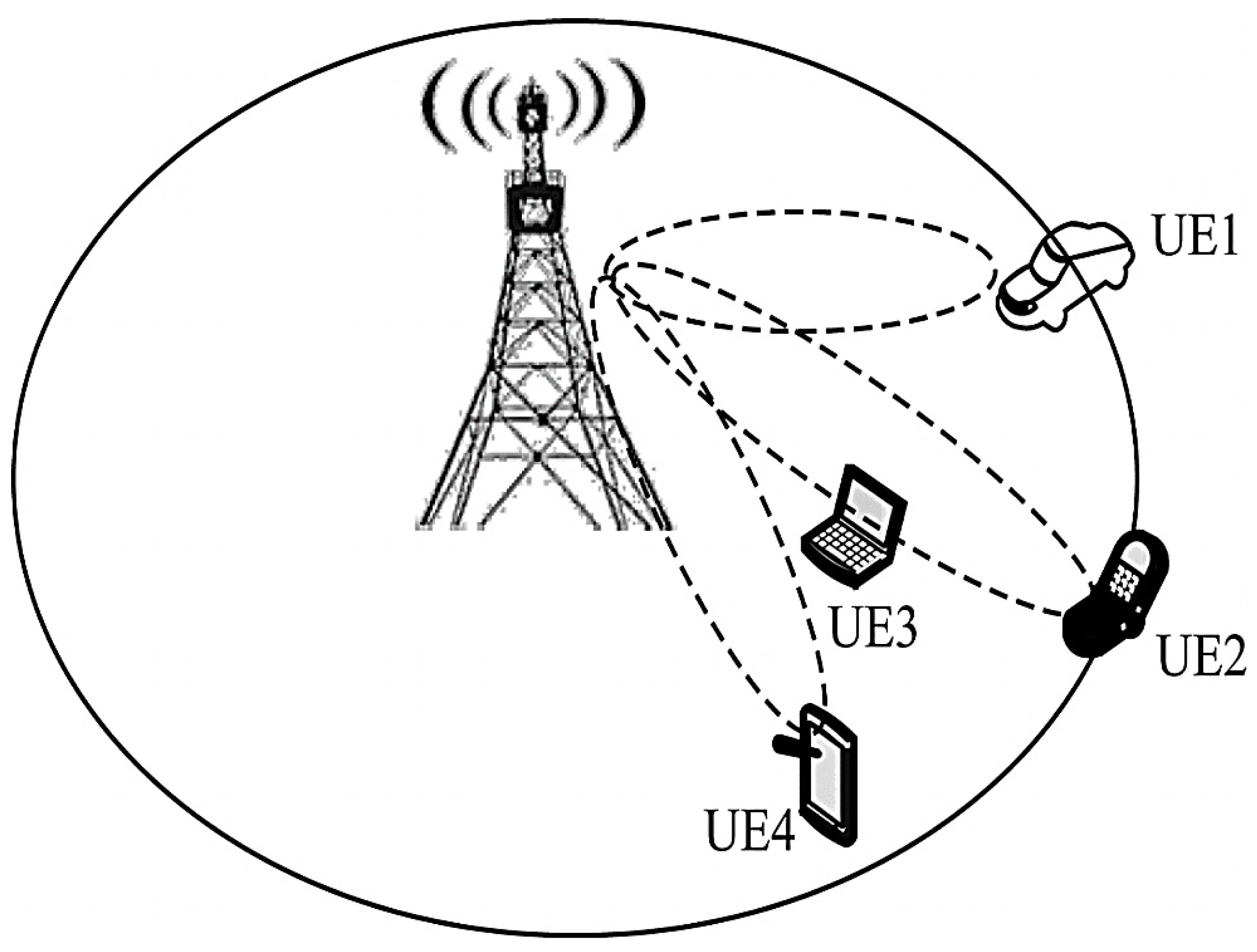
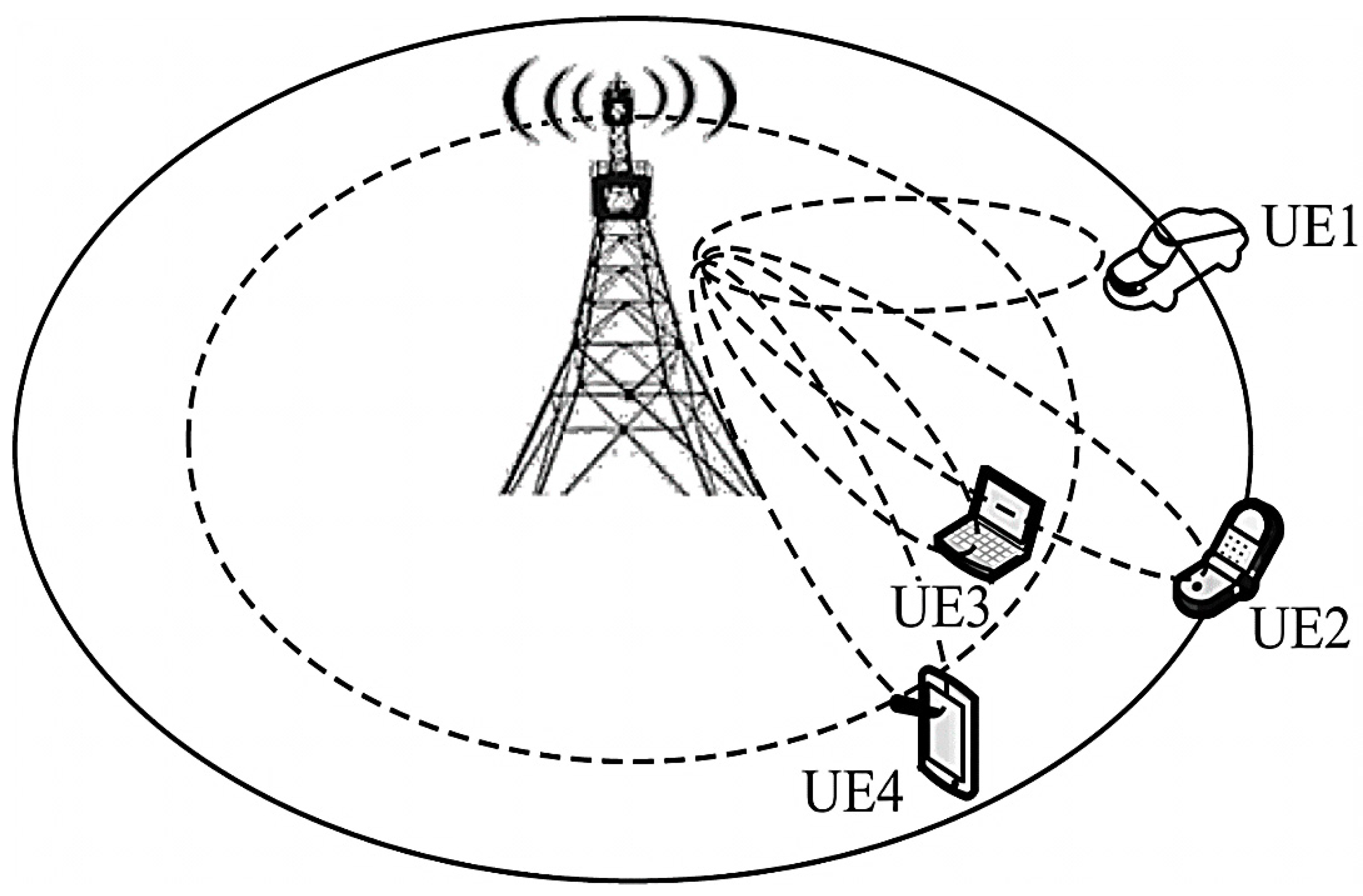
The traditional base station is equipped with a ULA array. As shown in
Figure 1, multiple beams for a terminal cannot be implemented in the vertical plane, so that the base station can form three beams in the horizontal dimension to align users with different angles from the base station, but in the horizontal dimension. Users with the same angle as the base station, such as User Equipment 2 and 3 (UE2 and UE3), whose beams interfere with each other. The 3D-MIMO technology provides vertical plane beamforming. As shown in
Figure 2, UE2 and UE3 can be distinguished in the vertical dimension to form the beams that are aligned with them to serve them, thereby controlling the interference of adjacent cells and improving the spectrum efficiency [
19].
This paper adopts the space division multiple access (SDMA) heterogeneous network system model composed of the microbase station and macro base station and multiuser. The distribution of micro base station follows the isomorphous Poisson Point Process (PPP) , with a density of . Each micro base station is equipped with an root antenna and the transmission power is ; the distribution of macro base station follows the isomorphism PPP , where the density is , each macro base station is equipped with antennas and the transmission power is . Each base station serves users, and , and it is assumed that the user obeys the independent stable point process and is randomly distributed in a circle whose radius is centered on the serving base station. For the fading model, it is assumed that all point-point channels obey the unitary mean of independent, identically distributed Rayleigh block fading, and the received power varies with distance by , where is the path loss index and .
The channel vectors from the micro base station , the macro base station, and the macro base station to the user are represented as , , , respectively, which are all composed of independent complex Gaussian random variables with zero mean unit variance. The normalized transmitted signal vectors of the micro base station , the macro base station, and the micro base station are respectively represented as , , , and the transmitted signal vector is a linear function , where is the data symbol of the user, is the unit norm beamforming vector for the user.
Because the transmission power of the micro base station is low, the macro cell users far away from the micro base station can only obtain a small gain even if the macro base station and the micro base station cooperatively transmit data under the coordinated multipoint (CoMP) mechanism [
20]. Therefore, this article only analyzes downlink information transmission for users in the micro base station. Assuming that the serving base station of each user is the closest base station to it, the micro base station serving the
specific user
is represented as
. Assuming that it is located at the origin, the distance between
and
is
. Then the
received sithe gnal can be expressed as:
where,
,
equivalent power allocation is used for analysis,
is the distance between the user and the
macro base station in micro base station
,
is the distance between the user and the
micro base station in the micro base station
,
is the additive white Gaussian noise with variance
.
In this paper, a limited feedback mechanism is adopted, and the base station can only acquire part of the channel state information (CSI) [
21]. The micro base station
and the user
keep the same quantization codebook
, which contains
unit norm vector codewords. The
user selects the quantization vector (codeword)
closest to the channel direction
from the codebook with
bit, and the user selects the optimal codeword from the codework by receiving the SNR maximization criterion:
After searching for the best-quantized codeword, the user feedbacks the index of the codeword to the base station using
bit. After the base station receives the index, the codeword corresponding to the index is found as a beamforming vector in the codebook, and then the related signal processing is made [
22].
The received signal interference–noise ratio (SINR) of user
is given by:
Among them, , is the inter-cell interference from the macro base station Poisson domain , is the inter-cell interference from the micro base station Poisson domain , is the inter-user interference in the cell estimated from the quantized CSI.
The system throughput, that is, the regional spectrum efficiency, is defined as the product of the absolute coverage probability and the maximum sum rate of transmission information per unit area. Let
be the
threshold, then the system throughput can be expressed as:
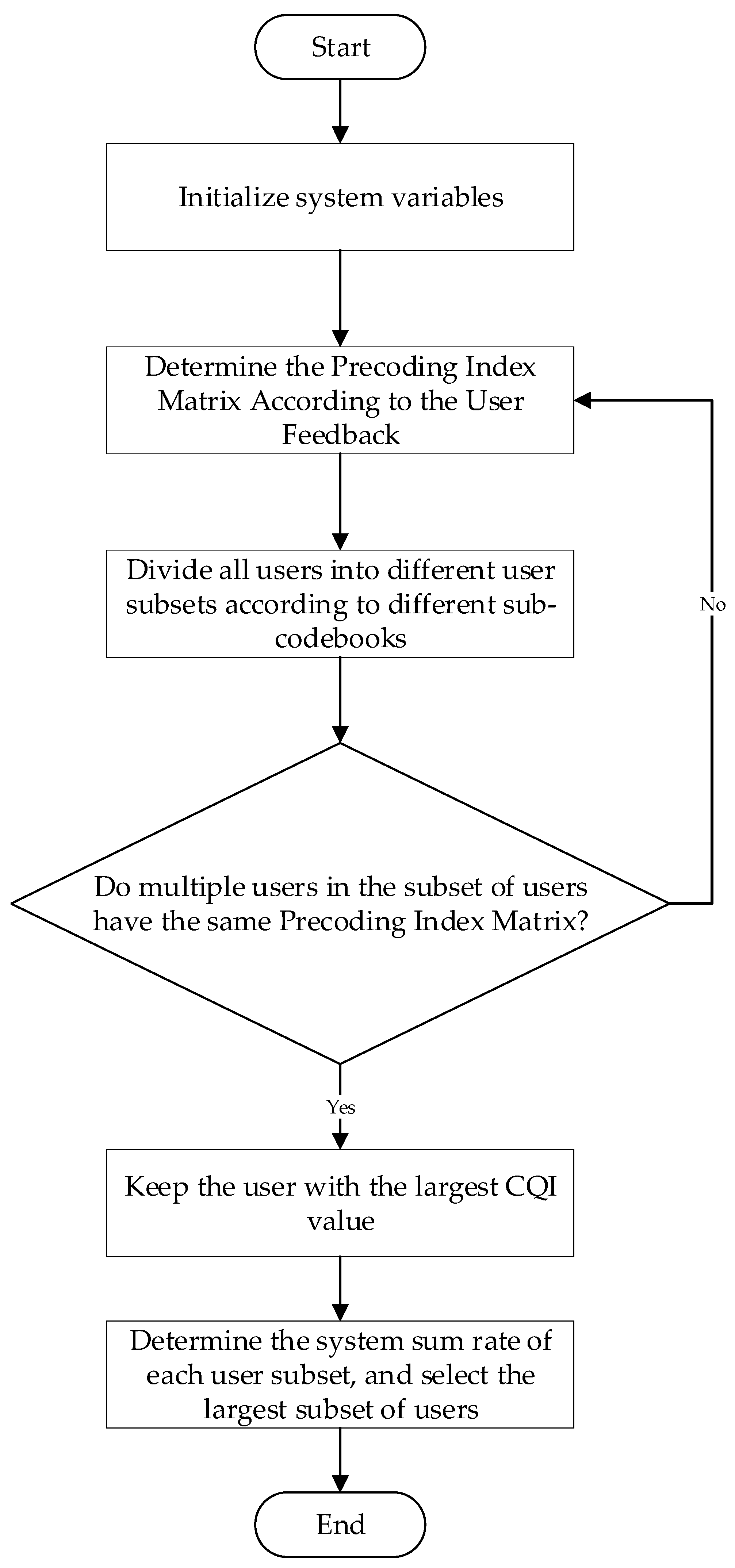
The flowchart in
Figure 3 explains the system procedure.
4. System Performance Analysis Based on Random Geometric Finite Feedback
According to the statistical characteristics of the random distribution of channel gain and Laplace transform, the system outage probability can be obtained [
21,
23]:
where,
.
According to the probability density function (PDF) and cumulative distribution function (CDF) of the radius`
in the 3D Poisson process, the inter-cell normalization from the Poisson domain
of the microcell can be obtained through the probability generation functional (PGFL). The Laplace transform
of the interference
can be expressed as:
By expanding and integration process we get:
Putting limits and rearranging to PGFL form we get:
where
is the PGFL. The Laplace transform
of the inter-cell normalized interference
from the macro-cell Poisson domain
can be expressed as:
For the interference term
.
represents the quantized distortion angle between
and
, decomposing the normalized channel vector
, where
is an isotropic unit norm vector that is distributed in the null space of
and is independent of
. Since
and
are independent, they are
[
23] and are independent of the quantization error
. To normalize interference between users, we can write:
Among them,
,
,
and
are independent of each other,
which follows the exponential distribution
[
22]. Let
, then
. Therefore, normalize the inter-user interference
The Laplace transformation of
is:
Putting Equations (12), (13), and (15) into Equation (7), we get:
Among them, is a gamma function.
From Equations (16)–(18), the throughput is related to the SNR at the base station density and the feedback overhead. The quantization error is reflected by the feedback overhead. The greater the feedback overhead, the greater the amount of information received by the base-stations from the user feedback, the smaller the quantization error, the more accurate the beam vector, the smaller the throughput loss, and the better the system performance. This article studies the improved 3D-MIMO precoding scheme.
5. Improved 3D Codebook Design
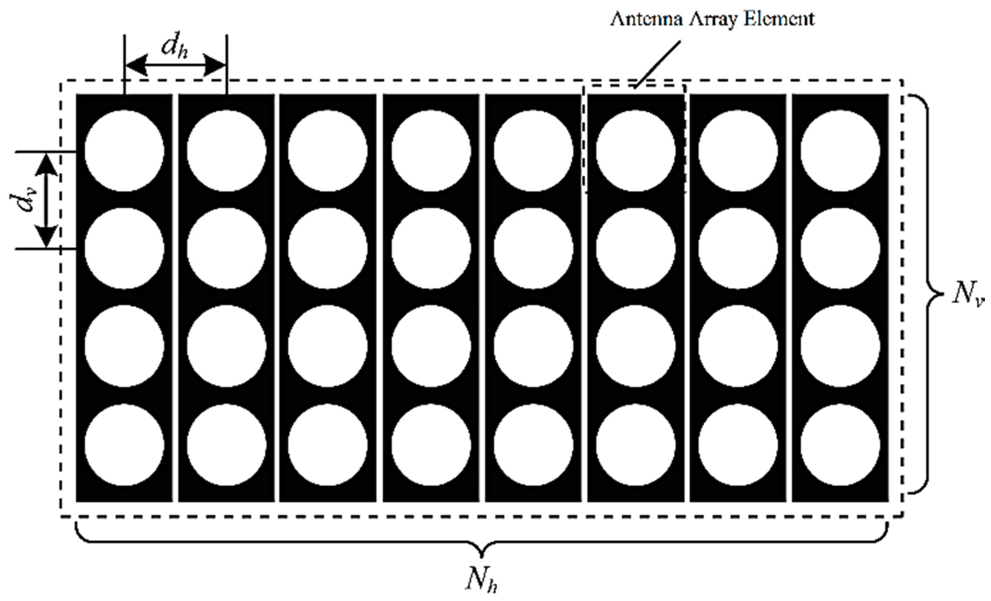
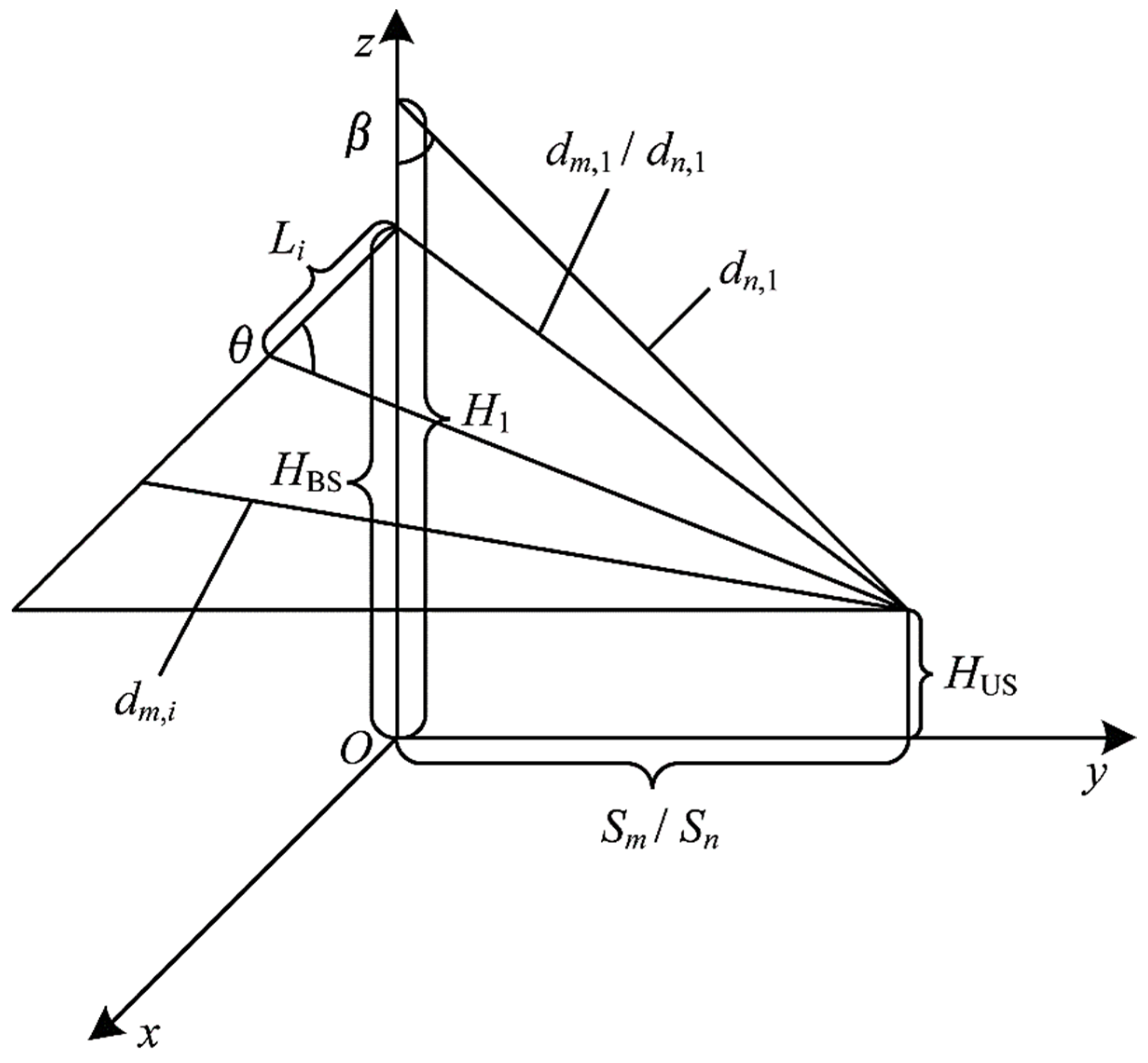
As shown in
Figure 4, the base station configures the UPA arrays, where the number of horizontal antenna array elements is
, the array element spacing is
, the number of vertical antenna array elements is
, and the array element spacing is
.
The horizontal codebook contains
horizontal codewords, and the vertical codebook contains
vertical codewords. As shown in
Figure 5, the base station transmit antenna height is
, the mobile subscriber receive antenna height is
,
is the distance between the
horizontal antenna array element and the base station, i.e.,
,
is the horizontal distance from the base station antenna for the beam alignment position formed by the
horizontal codeword.
The horizontal emission angle
of the beamforming the
codeword is:
The base station antenna array phase difference is given by:
The
horizontal codeword can be expressed as:
where
is the signal wavelength and the phase of the first antenna element is assumed to the reference phase 0.
Assuming that the horizontal distance of the beam alignment position formed by the
vertical codeword from the base station antenna is
and the height of the first vertical antenna element is
, the vertical downtilt angle of the beam formed by the
codeword is:
The base station antenna array phase difference is given by:
Then the
vertical codeword can be expressed as:
Combining horizontal and vertical codebook design, the Kronecker product codebook for improved 3D-MIMO can be expressed as:
Substituting the codebook into the system model to guide beamforming can optimize the system performance.
Since each array element has its own specific location in both horizontal and vertical directions, if the UPA array developed by the base station is regarded as a whole, the beam will be too divergent. In order to make the beam pointing more accurate, it is necessary to consider the position of the array element in the horizontal and vertical directions at the same time. Based on previous studies, this paper considers the influence of the adjustable range of the horizontal launch angle on beamforming accuracy. Using the phase of the antenna array element and the phase difference between the array elements, an improved horizontal and vertical codeword is proposed and used the Kronecker product to get the improved precoding codebook.
6. Simulation Results
Consider a two-layer 3D-MIMO heterogeneous network consisting of the macrobase station, a micro base station, and multiple users, where the serving base station is a micro base station. Let the serving base station is
collaborate with other micro base stations and macro base stations that greatly interfere with user terminals. At this time, the interference of the user terminal can be eliminated as much as possible. This heterogenous network simulation environment is built by MATLAB, and the improved 3D codebook is brought into the process of system performance analysis. The simulation curve of the closed-form solution of the system performance analysis illustrates the impact of various performance parameters and the improved 3D precoding scheme on system performance. The main simulation parameters are shown in
Table 1.
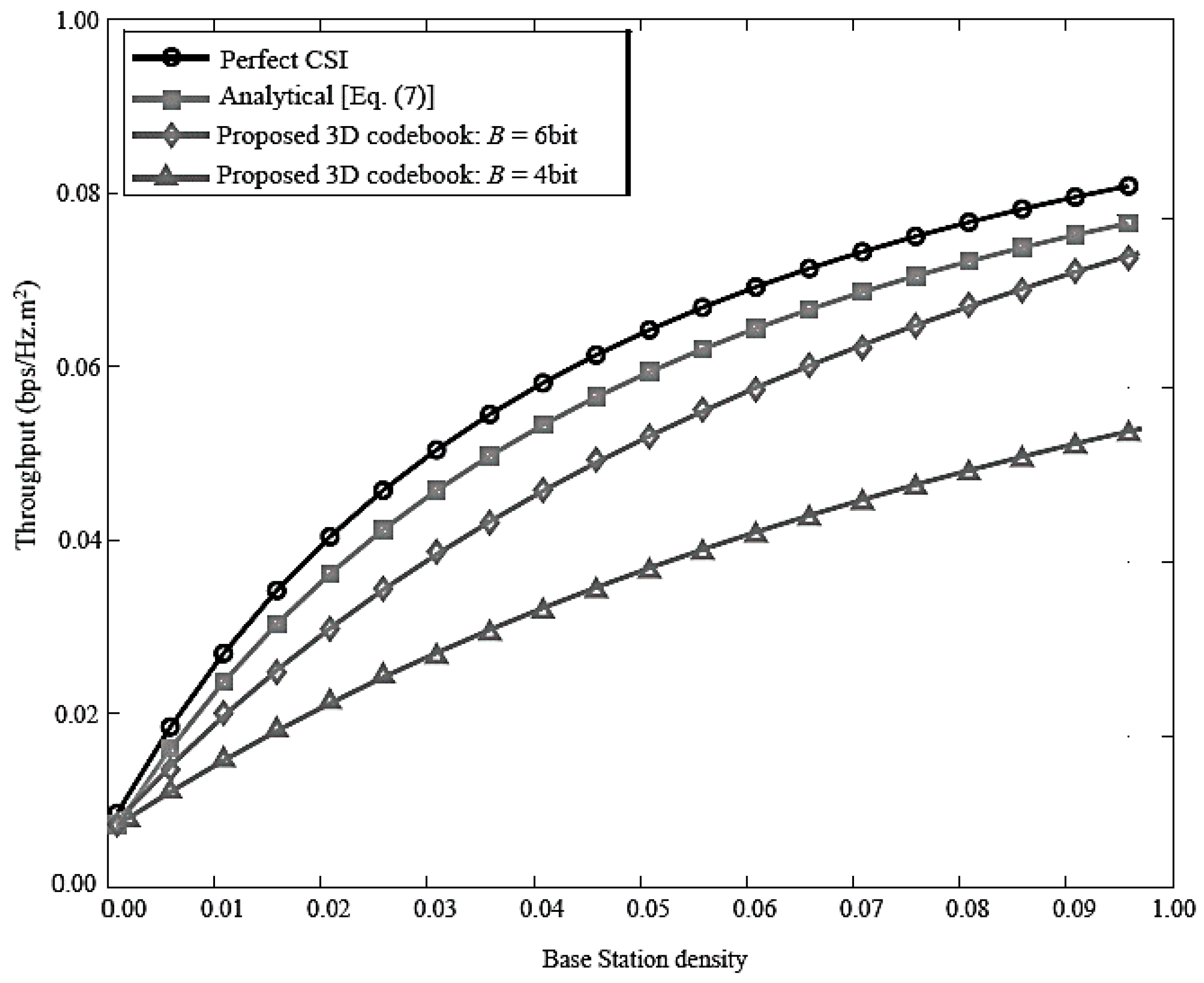
Figure 6 shows how the network throughput varies with the base station density. The proposed 3D MIMO codebook scheme is compared with perfect CSI condition for feedback bits of 4 and 6 respectively. The simulation results are consistent with the analysis results. As the base station density increases, the throughput gradually increases. It can be seen that proper adjustment of the base station density can increase system throughput and optimize system performance. Moreover, as the base station density increases, the impact of system performance caused by incomplete CSI becomes more serious. Furthermore, the system throughput curve when the base station receives perfect CSI is plotted as a comparison, indicating that the more feedback bits, the better the system performance.
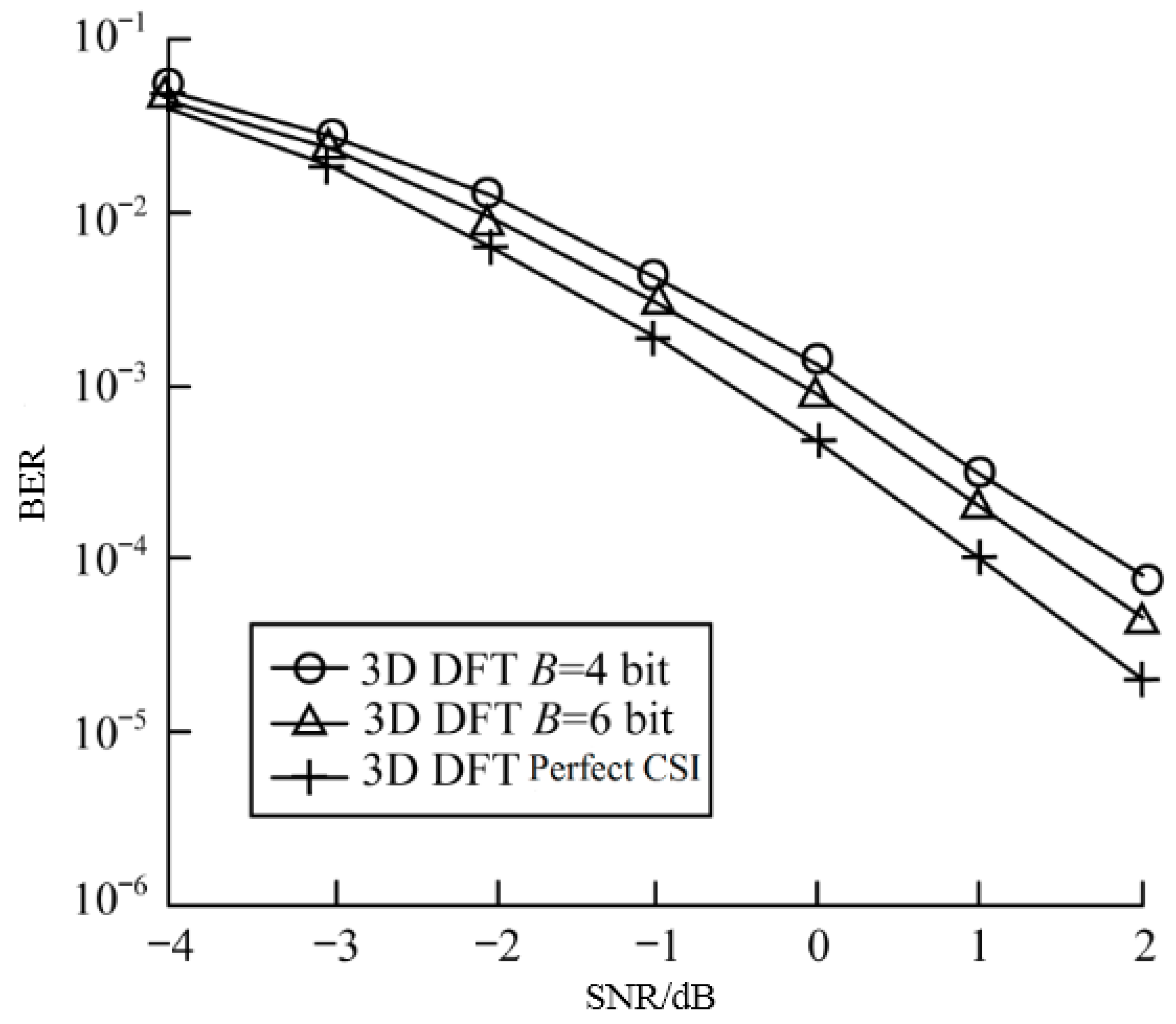
Figure 7 compares 3D DFT precoding scheme when the number of feedback bits is 4 bits and 6 bits, respectively, and perfect CSI, the BER of the system varies with the SNR of the base station transmitter. Simulation results show that as the number of feedback bits increases, the system’s BER decreases.
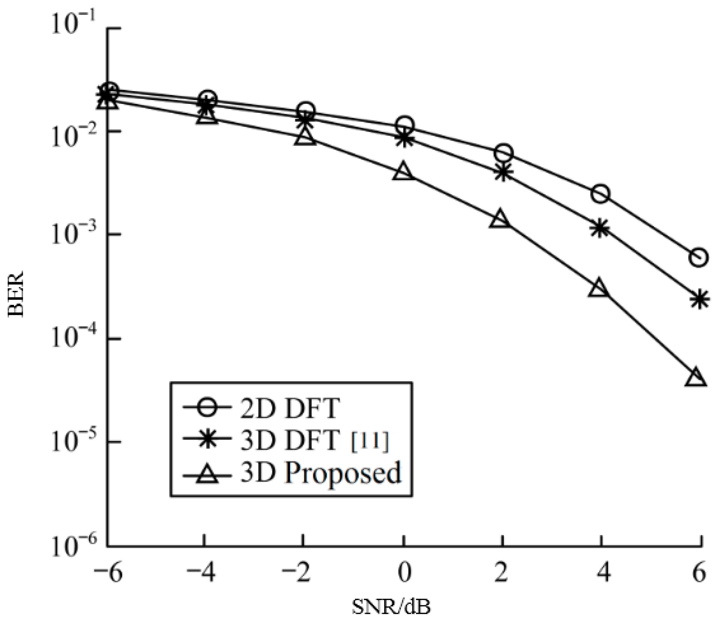
Figure 8 compares the use of DFT precoding schemes in 2D and 3D environments, respectively, under the BER, and in the 3D-MIMO channel model, the performance difference between the improved precoding scheme and the DFT precoding scheme proposed in this paper in terms of system BET. The traditional DFT precoding scheme is not suitable for vertical dimension codebooks in a 3D environment in which the base station employs both planar and planar antenna arrays due to the problem of adjustable dynamic range and vertical distribution of the vertical dip and tilt angle, and this paper considers horizontal emission jointly. The 3D codebook is constructed by angle and vertical down-tilt, so the performance of the improved precoding scheme proposed in this paper is better.
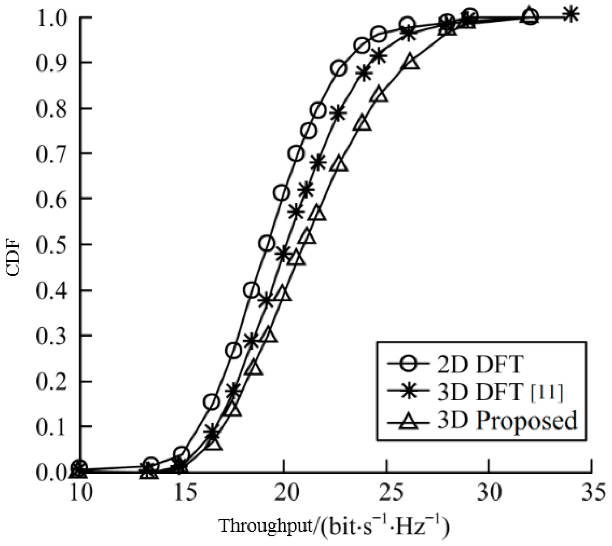
Figure 9 shows the Cumulative Distribution Function (CDF) curves for different codebook schemes. It can be seen from the simulation results that the 3D DFT precoding scheme can effectively improve the system throughput compared to the 2D DFT precoding scheme because it fully utilizes the vertical dimension of the UPA array. The improved 3D precoding scheme proposed in this paper jointly considers the horizontal adjustable range and the vertical down-tilt adjustable range, and considers the specific location of the antenna array elements rather than the UPA array as a whole, so it is more effective. The proposed codebook scheme controls inter-user interference at the edge of the cell to significantly increase system throughput.
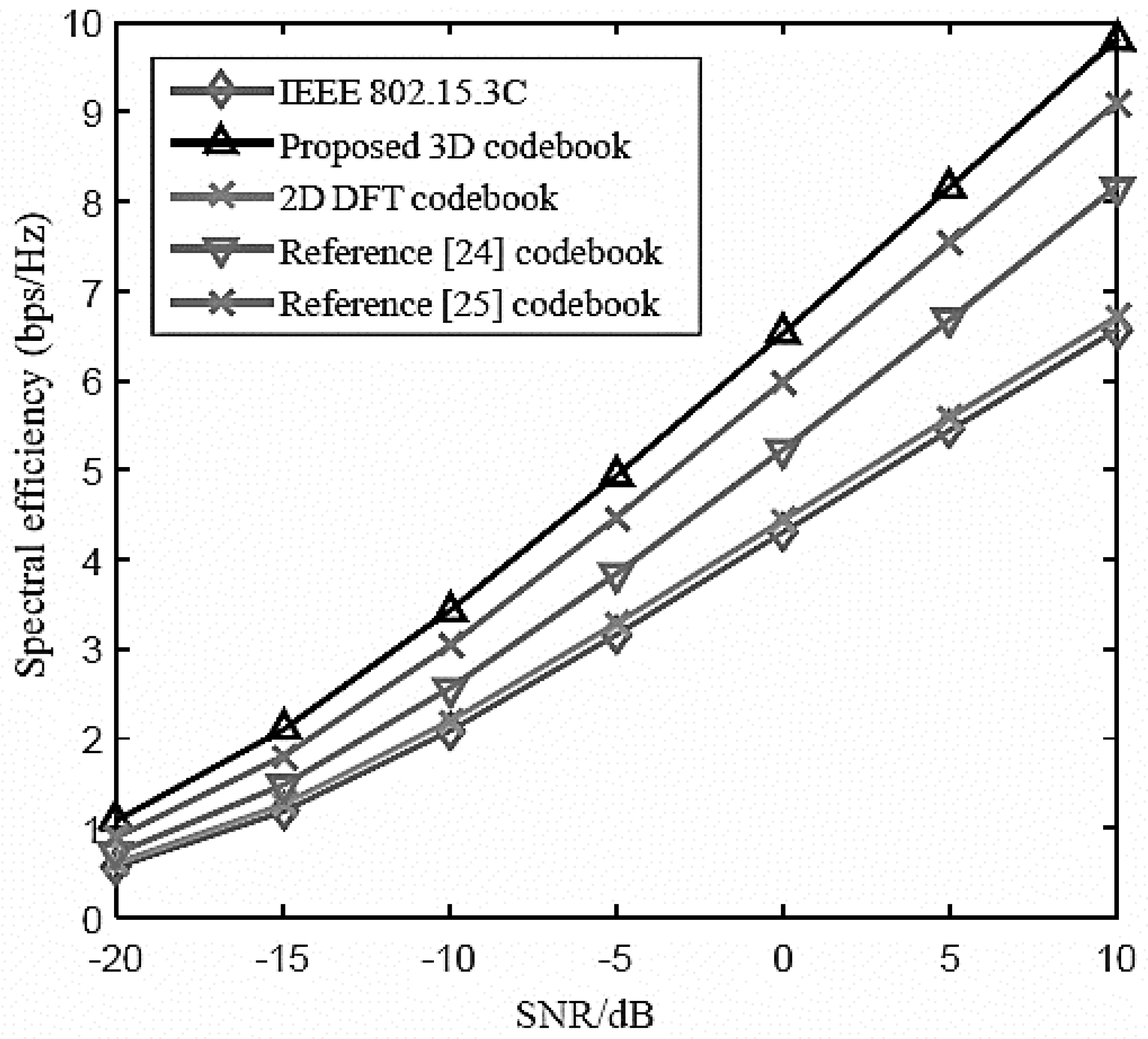
Figure 10 compares the spectral efficiency (SE) versus SNR of the proposed 3D codebook scheme with other state-of-the-art codebook schemes. As can be seen from
Figure 10 that the proposed 3D codebook scheme outperforms the other codebook schemes which show its superior performance over other codebooks schemes. Moreover, the rate gap between the proposed scheme and other schemes increases with increasing SNR which means that the proposed 3D codebook scheme shows better SE performance in low as well as high SNR level. Such results cover the real-world aspect of the MIMO system deployment where the SNR changes due to certain channel impairments and there is a need for a flexible and robust codebook scheme which should provide better service in wireless communications systems.
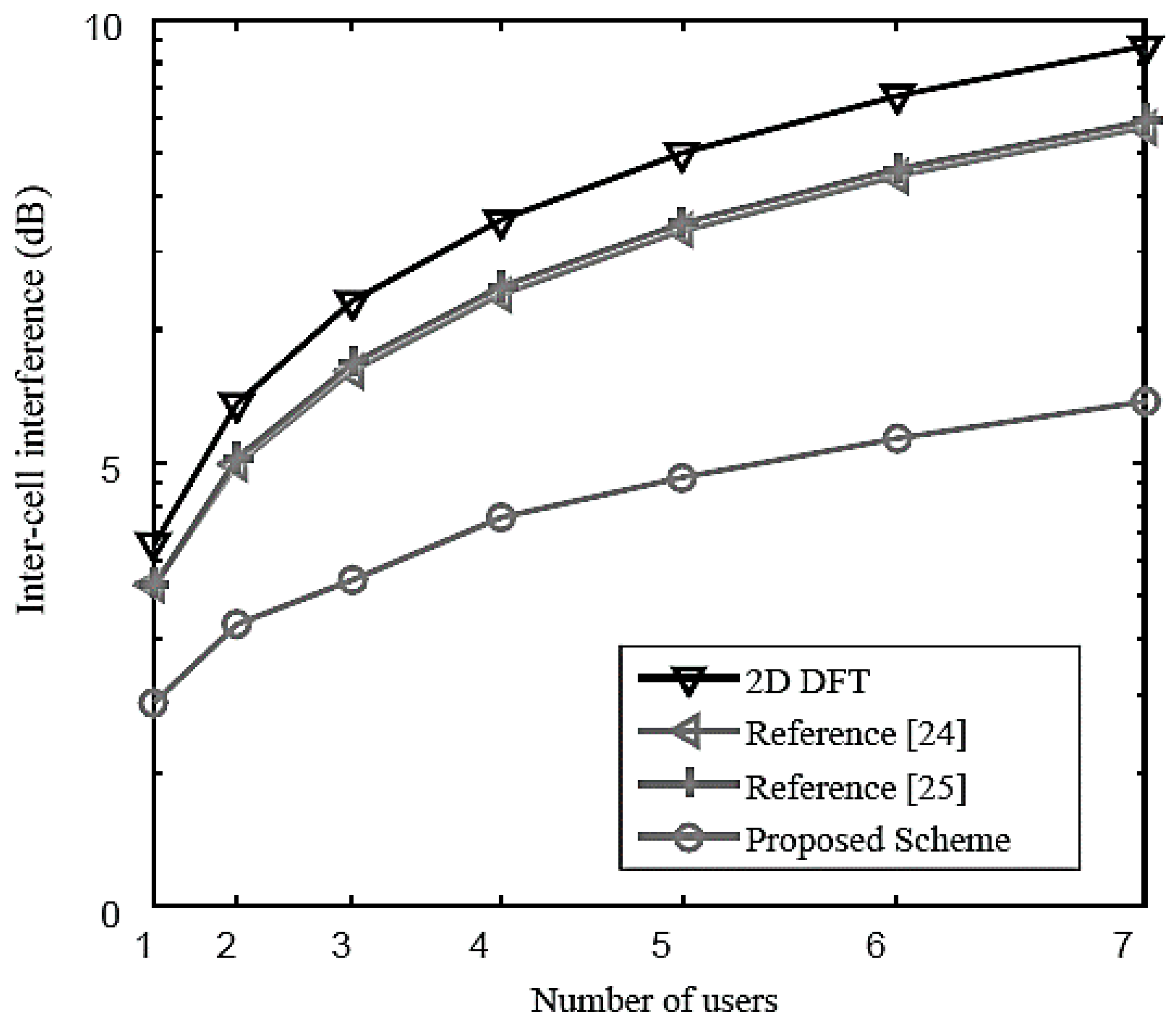
Figure 11 shows the impact of the inter-cell interference on the system using different codebook schemes. As can be seen from the
Figure 11, when the number of users increases, the interference from different cells increases which causes communication interruption. Moreover, the proposed 3D codebook scheme shows have lowest Inter-Cell Interference (ICI) level which is much better as compared with those of previous papers [
24,
25] and 2D DFT schemes. Therefore, the proposed 3D codebook scheme also shows better ICI performance which obviously makes it an attractive candidate to deploy in real-world application scenarios.
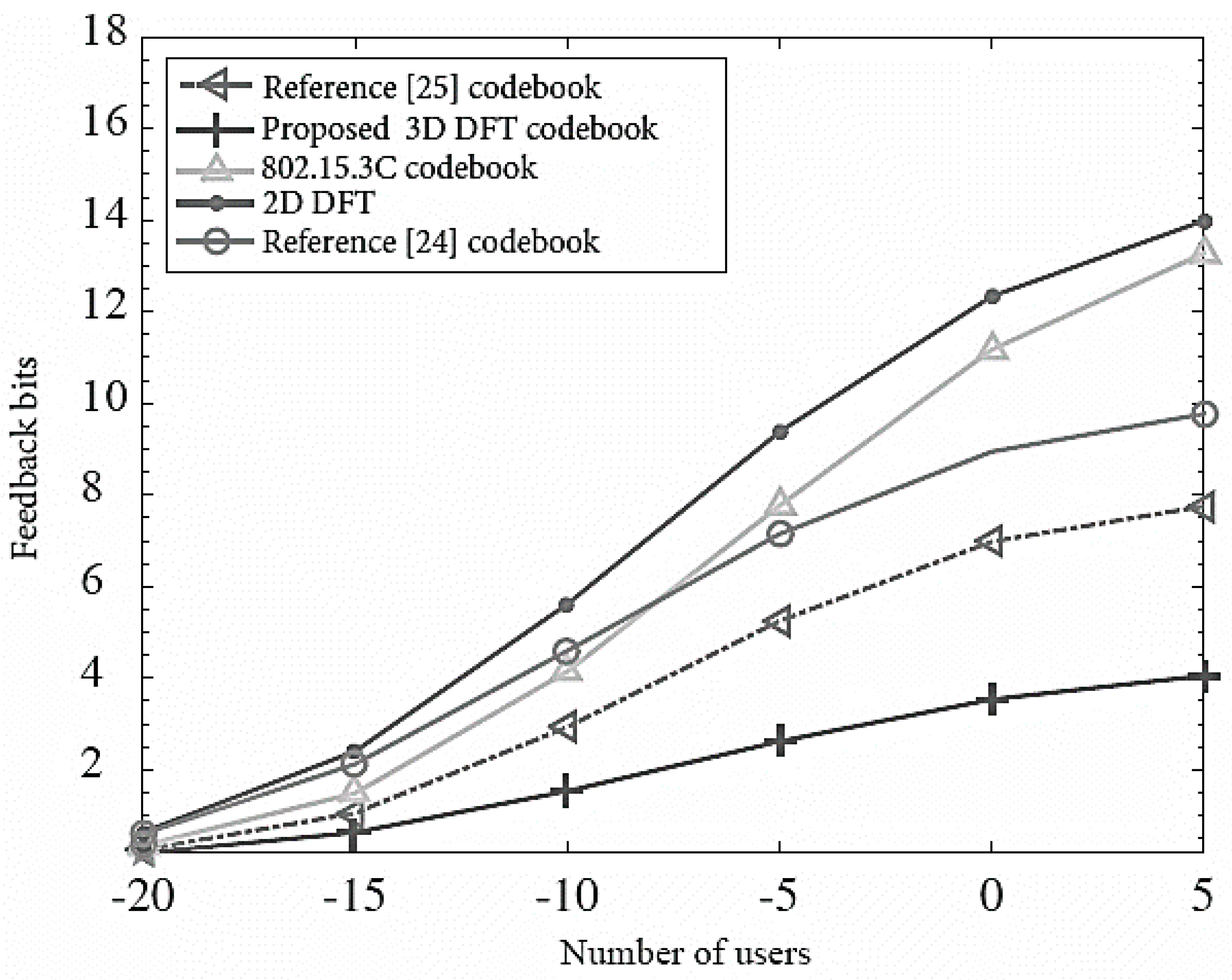
Figure 12 compares a number of feedback bits required versus the number of users for the proposed 3D MIMO codebook and other state-of-the-art schemes. It is clear from the results that the proposed scheme shows efficient performance as it requires a smaller number of feedback bits for channel estimation whereas the other codebook schemes require large number feedback bits which indicates that such schemes have large feedback overhead. Therefore, such comparison proves that the proposed 3D MIMO codebook scheme is also cost-effective as we know that feedback bits directly impact the system implementation cost, thus the proposed scheme is time-efficient and cost-efficient.
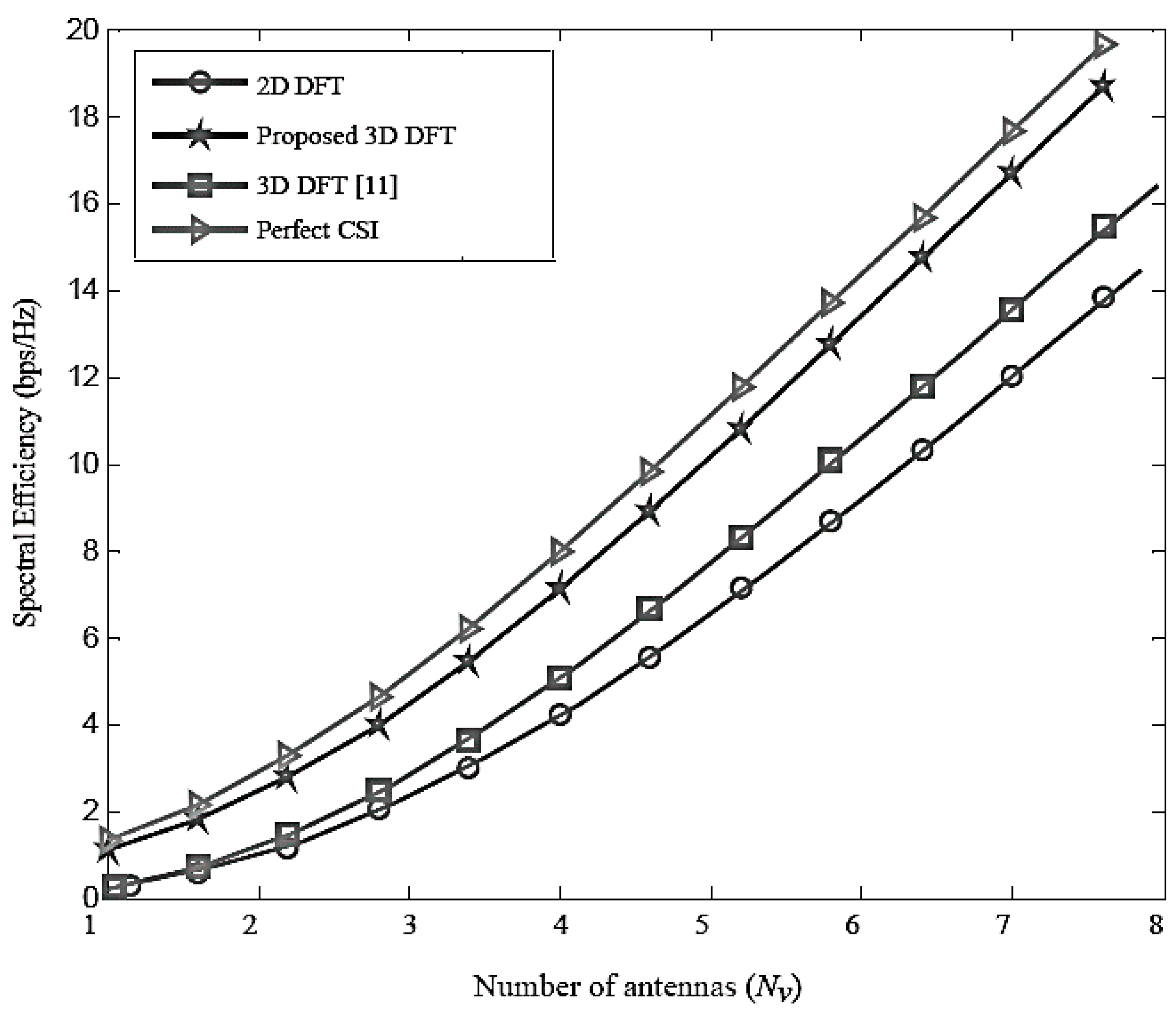
Figure 13 compares the spectral efficiency of the proposed 3D MIMO codebook scheme against the number antennas (
Nv) and compares it with other schemes. As can be seen from
Figure 13, when the number of antennas increases, the spectral efficiency increases for all codebook schemes. Furthermore, the proposed 3D DFT codebook scheme shows better performance than 2D and 3D DFT [
11] codebook schemes. It is worth notable from the results that the proposed codebook scheme shows nearly optimal SE performance as its curve is closer to the ideal CSI performance. Therefore, such results show that the proposed codebook scheme have efficient performance in case of a large number of antennas.


