Structural Improvements in Consensus-Based Cooperative Control of DC Microgrids
by
 , and
, and
Muhammad Adnan Mumtaz
* ,
,
Muhammad Mansoor Khan
,
Xiangzhong Fang
*,
Muhammad Umair Shahid
and
Muhammad Talib Faiz
Department of Electronic Engineering, School of Electronics, Information & Electrical Engineering (SEIEE), Shanghai Jiao Tong University, Shanghai 200240, China
*
Authors to whom correspondence should be addressed.
Electronics 2019, 8(2), 187; https://doi.org/10.3390/electronics8020187
Submission received: 30 December 2018
/
Revised: 31 January 2019
/
Accepted: 1 February 2019
/
Published: 6 February 2019
(This article belongs to the Special Issue Power Quality in Smart Grids)
Abstract
:This study is dedicated to establishing a comparative analysis of the performance of different local controllers on the cooperative control of DC microgrids. One of the elementary and challenging issues in DC microgrids is the assurance of fairness in proportional current sharing while accomplishing voltage regulation in parallelly connected distributed energy sources. In this work, structural improvements are proposed to enhance the system stability and control performance. A finite-gain controller was employed in the outer voltage control loop with a simple proportional (P) controller in the inner current control loop of a converter. Due to the finite-gain controller, droop-like power sharing was achieved without droop coefficient. In order to further enhance the power-sharing accuracy and DC voltage regulation, a different method was adopted in consensus-based cooperative control to estimate the average current and average voltage difference. Moreover, small signal analysis was used to scrutinize the stability and control performance of the local controller, while different communication delays and current disturbances were applied to examine the performance of the controller. Finally, a four-node-based DC microgrid setup was developed in MATLAB/Simulink environment, and simulation results of the proposed and existing techniques were scrutinized. The simulations results demonstrated the effectiveness of the proposed controller.
1. Introduction
1.1. Motivation
As a new paradigm of electrical power systems, microgrids are an appealing solution to integrate sustainable energy sources and distributed generators into the grids. Basically, a microgrid is a small distribution system that has the ability to interconnect with electrical storage systems, distributed generations, and multiple users [1]. Compared to the synchronous power plant, microgrids have either very low amount or no inertia. Due to this reason, these systems have higher stability. The main characteristic of a microgrid operation is that it can be operated in grid-connected as well as in an islanded (autonomous) mode of operation. Islanded mode is usually initiated for maintenance or due to economic reasons. In grid-connected mode, energy can be injected into the main grid, providing economic benefits to users. A storage-based or generator-based microgrid can potentially fully compensate the intermittency of renewable sources. In this way, microgrid can present itself to the grid as a constant load. Japan is currently leading in microgrid demonstration projects. Aomori microgrid in Hachinohe started its operation in October 2005. In the United States (US), microgrid projects are expanding slowly. The well-known microgrid project in the US has been pursued under the Consortium for Electric Reliability Technology Solutions (CERTS) since 1999 to improve the reliability of power systems [1,2]. Recently, microgrids have gained a lot of attention due to their significant merits like higher efficiency, sustainability, system stability, higher expandability, better power quality, security, and so on. Most power grids are AC systems, so AC microgrids have been discussed frequently in recent literature [2,3]. Power systems can be considered as centralized and decentralized energy systems. Centralized energy systems are mostly operated on fossil fuels and need huge investment to establish the distribution and transmission network so that power grids can penetrate rural areas. In decentralized energy systems, generation of power is usually located near the demand centers so that local energy requirements can be realized easily. Typical examples of decentralized energy systems are grid-connected (GC) and stand-alone (SA) systems [4]. The centralized networks are more mature in most countries because higher cost is required to replace these energy systems. DC microgrids have attained much popularity in recent years due to their significant advantages over their AC counterparts, including (i) fewer number of AC/DC conversion stages; (ii) better efficiency and power quality; (iii) no issues like frequency synchronization, transformer inrush current, and reactive power; and (iv) reduced volume, better flexibility, and lower cost [5,6,7,8,9]. DC microgrids can be installed for commercial, industrial, and outdoor installation purposes.
Two control objectives have been reported in literature for the secondary/primary control of DC microgrids: (i) proportional load sharing, so that power can be fairly dispatched from distributed generations to distributed load and (ii) voltage regulation, so that the desired DC bus voltage can be maintained [10,11,12]. Although several control structures have been discussed in recent literature to realize the secondary/primary control objectives noted in [10,11,12], in all these control techniques, primary control objectives have been realized with conventional PI controllers in current and voltage loop of buck converter with decentralized droop control. Therefore, there is a need for an alternative approach to local controller structure with cooperative control that is capable of realizing the DC microgrid control objectives more efficiently and has better stability, which is the first motivation of this study. Furthermore, the DC microgrid control structure is usually characterized into three types: (i) centralized control, (ii) decentralized control, (iii) distributed. Traditionally, centralized control structures implement secondary and tertiary control. In centralized control, the central controller is responsible for collecting the information from all distributed nodes and AC/DC loads. In this way, the system can achieve better regulation and current sharing. However, this technique sometimes becomes impractical, especially in cases of single point of failure or when large-scale penetration exists in distributed generations [13,14]. The implementation of the centralized control technique is also very expensive, requiring a large communication structure with adequate bandwidth to exchange information quickly and precisely [15]. In order to improve microgrid robustness, expandability, and reliability and reduce the capital cost, it is highly recommended that distributed control structures are adopted. The aim of such a controller is to have the ability to fulfill the requirements of DC microgrid control objectives. A distributed control structure requires the support of a communication network [11,13,16]. While support of a communication network aims to improve system reliability and expandability, unfortunately, communication network limitations, such as communication delay, may affect or even degrade the system performance, stability, and reliability of consensus-based distributed cooperative control [17,18]. Therefore, while designing a consensus-based distributed cooperative control structure, it is imperative to consider the communication delay effect on the stability of a DC microgrid; this is the second motivation of this study.
1.2. Literature Review
The decentralized droop control technique is commonly implemented for current sharing by employing virtual impedance on the particular converter [12,19,20,21]. In droop-control-based microgrid systems, power sharing is accomplished by reducing the reference voltage of the controller linearly as the output current tends to increase [22]. Although the droop-based control strategy is simple, it suffers from poor voltage regulation and load sharing when the line impendence is significant [12,23,24]. The major drawback of the droop control strategy is that the current-sharing accuracy reduces when the voltage drop increases across the line impedance. The main reason for the poor DC voltage regulation is the voltage droop across the virtual impedance. The second reason is the mismatch of the output voltage between different participating converters. In [22] conventional droop strategy was adopted for voltage stabilization of a DC microgrid. The limitations of the conventional droop method were addressed in [25]. In [26], a primary voltage droop controller was proposed, and in [27], an adaptive decentralized droop controller was proposed to preserve the power sharing stability, of paralleled inverter-based DG units. However, these conventional approaches did not produce very satisfactory results for voltage regulation and load sharing. Consequently, for the enhancement of power-sharing accuracy and DC voltage regulation, an improved droop control technique was discussed in [12]. The results from the mentioned technique were adequate, but due to the use of PI controllers in the inner and outer loop of the local controller, the stability of these systems tends to decrease as the number of participating nodes increases, which results in poor transient response. In order to improve the efficiency and stability of the system, the structure of the local controller was modified in [13]. The stability of the local controller was better, but the performance of the voltage regulation was not satisfactory [13]. Communication network delays are inherent; therefore, due to requirements of data processing and transmission, delay of the system cannot be avoided [18,28,29]. The presence of communication delays can deteriorate the system control performance and cause instability. In [28], a delay-dependent robust load frequency control was studied by considering time delays. The impact of communication delay on secondary frequency control was discussed in [29], and a gain scheduling method was suggested to compensate for the communication delay. In [30], a ring communication structure with communication delay was discussed, while consensus network problems were discussed with or without communication delay in [31]. To the best of the authors’ knowledge, not much research has been conducted to investigate the impact of communication delay on the system control performance to ensure a good bandwidth.
1.3. Contributions
The contributions of this paper are as follows:
- Finite-gain voltage controller is introduced in the outer voltage loop with a simple proportional (P) controller in the inner current control loop. In this way, droop-like performance can be ensured without droop control.
- A different method is adopted in the consensus-based cooperative control to estimate the average voltage and current difference. Proportional current sharing and DC voltage restoration can be guaranteed by updating the single voltage correction term of the consensus control layer.
- The proposed control technique does not require prior knowledge of the nodes, so the proposed technique is scalable and has plug-and-play capability.
- A sparse communication network spans across the DC microgrid, due to which neighbors can interact with each other. This is different from the centralized technique.
- In order to ensure a good bandwidth and better control performance, the impact of communication delay is considered and analyzed. The voltage control loop bandwidth is also considered with the increasing number of nodes.
- In the presence of disturbance, the convergence time (disturbance rejection time) of the proposed controller is compared with the conventional power-sharing techniques.
2. Overview of Existing Techniques
2.1. Conventional Droop-Control-Based Technique
2.1.1. Local Controller
The primary responsibility of a local controller is to regulate the local current and voltage to meet the stability requirements and control operation. Inner and outer loop technique is used to perform this task. In the outer voltage loop, the PI controller is employed, and the output signal of PI is considered as a reference for the inner current loop, Iref, as shown in Figure 1.
where and are the gain coefficients of the proportional integral controller. The buck converter duty cycle, D, is written as follows:
where represents the inductor current of the converter, is the voltage output, and represents input DC voltage. The droop control method is adopted to realize the power sharing between parallel converters with reasonable droop gain. Due to the current-fed droop method, the voltage reference is modified and can be written as follows:
where is the droop coefficient, and represents the voltage reference for the n-th node.
2.1.2. Cooperative Controller
In order to enhance the proportional load sharing and DC voltage regulation, the average current and average voltage PI controllers are employed. In this cooperative controller, two correction items are generated, namely, δvi and δii for the node i. These correction terms are further input to PI controller to update the voltage reference of the local controller. The voltage and current correction items can be written as follows:
where , , , and are the gain coefficients of the PI controllers. In the average voltage controller, reference voltage is , and the average voltage is controlled to restore the output voltage at the reference value. Similarly, the reference value of the average current controller is , where represents the current sharing proportion. Therefore, proportional current sharing and DC voltage regulation are achieved with the help of the average current and average voltage PI controllers. The reference voltage can be expressed as follows:
The average value of the voltage and the average value of the current are given as follows:
2.2. Conventional Droop-less Technique
Local Controller
In order to enhance the stability and control performance of the local controller, its structure was modified. A simple P controller was employed in the local voltage loop in place of the conventional PI controller. The structure of the modified local controller is shown in Figure 2. The modified current reference is expressed as follows:
where is the gain coefficient of the simple P controller. The current loop was similar to what was discussed previously.
In this technique, the control objectives of the DC microgrid were realized without droop control. In this method, the average voltage and current difference were estimated with a different method in which the average value of voltage was measured in the local node with the aid of estimated average value of voltage of its adjacent nodes.
2.3. Limitations of the Existing Techniques
The decentralized droop control method [12] and technique [13] can achieve the control objectives of the DC microgrid, but there are some limitations that need to be addressed. Firstly, in [12], two PI controllers were employed in the inner and outer loop of a local controller to achieve the responsibilities of primary control. As the number of participating nodes increase in a system, the number of PI controllers also increase, which results in poor transient response and higher oscillations. Therefore, achieving the control objectives of the DC microgrid becomes more difficult when the system consists of multiple nodes with such a type of local controller. Secondly, the droop control method also has limitations, such as voltage deviation and poor current-sharing accuracy. Due to droop control action, voltage deviation exists. When the output current of multiple nodes is not equal to zero, then it results in deviation in voltage, and this value changes with the amount of load current. In order to keep this voltage deviation in the maximum acceptable range, the droop coefficient value should be moderate. In order to measure the average value of the current and voltage, information from each node is collected in the local node. Thus, the ring communication network can be considered, which can cause limitations like poor connectivity, higher communication delay, and expandability problems. In case of link failure, the primary controller is not able to realize the secondary/primary control objectives of the DC microgrid. The other control technique [13] based on a modified local controller can fulfill the control objectives of the DC microgrid, but voltage regulation is not much satisfactory. In this study, considering the limitations of both techniques, structural improvements are proposed for the consensus-based cooperative control of DC microgrids.
3. Proposed Technique
To improve the efficiency of the DC microgrid, a novel local controller structure is proposed. A finite-gain controller is employed in the outer voltage control loop with a simple P controller in the inner current control loop of the buck converter. The gain margin of the finite-gain controller is better compared to the PI controller, so droop-like performance can be achieved without droop coefficient because the steady state response of the finite-gain controller is better than the combination of the droop and the PI controller. Due to this, the response of the finite-gain controller for load sharing and voltage regulation is similar to droop-control-based system. In the proposed local controller, the P controller in the current loop can reduce the relative degree of the transfer function, and the finite-gain controller has better gain margin. Therefore, the overall stability of the local controller is superior to the existing local controller structure. In distributed cooperative control, neighbors have the ability to cooperate with each other by sharing information to generate the voltage correction item. In this cooperative control, only single correction item is enough to simultaneously realize the two conflicting objectives of the DC microgrid.
3.1. Proposed Local Controller
The finite-gain controller is implemented in the outer voltage loop in place of the conventional PI controller, as shown in Figure 3. Then, the modified current reference, , can be written as follows:
where p is the pole and z is zero, and z must be greater than p. Here, k represents the DC gain, and its value is adjusted to achieve the desired steady state error and to get the desired overshoot. The lower value of k reduces the noise and tends to increase the phase margin. In designing the finite-gain controller, the root locus method is adopted. First, a suitable ratio of is carefully selected so that the desired steady state error can be achieved according to the system requirements. The ratio must be greater than 1 so that it can adjust the gain crossover frequency to achieve the desired phase margin. The position of the pole and zero is near the origin. This way, they have a negligible effect on the system transient response. A simple P controller is employed in the current loop in place of the PI controller. The modified duty cycle for the buck converter can be stated as follows:
where kp is the gain coefficient of the P controller.
3.2. Cooperative Control Structure
In the secondary cooperative control, the neighbors share information with each other to enhance the DC voltage regulation and proportional load sharing between parallel converters. Using the neighbors’ information and its local measurements, each node updates its own control variables. This cooperation between nodes offers the global consensus of the desired variables, provided that there is proper communication between nodes. Two control objectives are considered, namely, proportional load sharing and global voltage regulation, which requires proper voltage set point for the particular converter. Cooperation of nodes at secondary cooperative control level helps to fine-tune the voltage set point for the local controller and minimize the current and the voltage residuals. Each converter at secondary control level transmits a dataset , to its adjacent neighbors for cooperation between converters. The dataset , contains three basic elements: measured per unit current , estimated average voltage , and the measured local voltage . Here, represents the current per unit (each converter) divided by its rated current , which can be expressed as , and represents the rated current of i-th converter. The per unit current defines the loading percentage of the individual converter.
On the other hand, node j receives data from its neighbor’s , through the communication network, having some design parameters that can be designated as data transfer gains, . In order to realize proportional current sharing and global voltage regulation, it is necessary to fine-tune the proper voltage set point of each converter. The proposed distributed cooperative structure is depicted in Figure 3, where information from the local controller and its adjacent neighbors is used to fine-tune the voltage set point The proposed droop-less local controller is the starting point, which acts on local information. Only single voltage reference term is enough to ensure relative current sharing and voltage regulation. Basically, this correction item is contributed through the cooperation of converters. The modified local set point voltage of each converter may be stated as follows:
The voltage controller, as shown in Figure 3, also further adjusts the voltage set point to regulate the DC bus voltages within an acceptable limit. In the secondary control, there is one voltage observer with a PI controller . The prime responsibility of the voltage observer is to roughly calculate the average value of voltages across the whole microgrid, and represents estimation for the node This estimated voltage is further equated with the global value of voltage reference . In case of any discrepancy, correction items are generated and adjusted by the controller to eliminate the mismatch and converge the microgrid toward better power sharing and DC voltage regulation. The voltage observer is a part of the voltage regulator block. Dynamic consensus framework is utilized to process information from neighbors and to calculate the average voltage across the DC microgrid.
Figure 4a shows the global averaging policy for each node of the distributed cooperative control. To estimate the average voltage difference in cooperative control, the observer uses the estimated value of the local node and processes the information of the neighbor’s estimates. The observer at node obtains information from its neighbor’s estimates . After this, the voltage observer upgrades its personal estimate using the adjacent neighbor’s estimates and measurement of the local node which can be written as follows [11]:
The protocol that is adopted in voltage observer to update the voltage set point is known as the dynamic consensus protocol. As depicted in equation (14), the local voltage is added in the estimation protocol. Thus, if any discrepancy in voltage occurs for node , then the local estimation reacts instantly. This results in the new variation in spreading in adjacent neighbors using the communication network and affecting the neighbors’ estimations. By differentiating Equation (14), we get the following:
where is the diagonal matrix and can be stated as Consequently, the global observer dynamics is stated as follows:
The voltage measurement vector carries the voltage measurement of all nodes. In the same way, the voltage estimation vector carries the estimated global average voltages of each node, which can be represented by vector . In the frequency domain, the equivalent equation can be written as follows:
The other part of the distributed cooperative control is a current regulator to ensure the proportional current sharing between parallelly connected nodes. The regulator for node i equates the per unit current with its adjacent neighbor’s weighted averaged per unit to estimate the value of current mismatch, δi.p.u [11].
where is the data transfer gain for the communication network, also known as communication link weight; represents the per unit current for the neighbor j; and represents the per unit current for node i.
where is the voltage correction term for node i, is the coupling gain of a proportional controller, and is the gain of the PI controller. In this cooperative control structure, only single correction item is enough to realize the secondary/primary control objectives of the DC microgrid. The stability of the proposed local controller is much superior to the existing conventional techniques, with a better power-sharing accuracy. If disturbance is applied, the disturbance rejection time of the proposed technique is much less compared to both the existing conventional techniques. Therefore, the viability of the proposed technique in terms of scalability and disturbance rejection capability is higher than both the recent conventional techniques. The comparison of power sharing, stability, and viability is given in Table 1.
4. Small Signal Analysis
The simplicity of the proposed local controller was discussed in the introduction section and also shown in Figure 3. The other structural improvements and merits have been discussed briefly in the proposed technique section. The small signal model has been widely used in recent literature for the analysis of system stability and dynamic control performance [29,32,33]. DC–DC buck converters considered for microgrids usually have higher switching frequency. DC–DC buck converters employed in this case study are nonlinear in nature. The small signal model is linear in nature, and it is constructed by considering DC working points, neglecting the harmonics of the system.
The small signal model of a DC–DC buck converter is shown in Figure 5, The two input signals are represented by and the two output signals are represented by In a buck converter, there are two DC working points: The state-space equation of DC–DC buck converter can be written as follows:
The transfer function from the input signal to its output signal and the output signal can be written as follows:
In this paper, the small signal model of both the existing and proposed techniques is considered in order to investigate the stability response and to acquire the frequency response of the local controller. Figure 6a shows the exiting droop-control-based technique [12], Figure 6b is the other existing control technique [13], while Figure 6c represents the proposed local controller. In Figure 6c, the finite-gain controller is used instead of the P controller because the finite-gain controller has more significant overshoot compared to the P controller. Using the finite-gain controller system can provide a faster response to achieve the desired objectives.
The local controller is based on the inner and outer loop control. Droop control is part of the local controller, as shown in Figure 6a. The proposed local controller is much simpler, due to the implementation of P controller in the current control loop, as an alternative to PI, and finite-gain controller in the voltage loop. The finite-gain controller has better gain margin than PI, and due to the P controller, the relative degree of control is reduced, and the system has lower transient time and oscillations. This small signal analysis is used to evaluate the stability behavior by considering the frequency response of and . Here, represents the disturbance current that is applied at output. By considering the small signal model, the root loci of for both the recent techniques [12,13] and the proposed technique with the increasing value of kp are noticed, and appropriate values are selected. The bode plot response of and are represented in Figure 7a,b, respectively. From Figure 7a, it can be observed that the phase and magnitude performance of the proposed technique is superior compared to the existing conventional techniques [12,13]. Therefore, the proposed droop-less local controller has better stability compared to the existing techniques. On the other hand, with the disturbance current the magnitude response of the proposed controller is superior to the existing techniques, while the phase performance of the existing controller [13] is slightly better than the proposed technique, as shown in Figure 7b. If the gain of the controller tends to increase in the outer voltage loop, then it will improve the steady state error, and the overshoot of the system also increases. Therefore, the stability of the proposed system would be reduced, but the system will achieve better current sharing. The inner current loop of the local controller reduces the effect of component variation by linearization and by shifting the system poles toward the negative real axis. However, due to the measurements of voltage and current not being precise enough, parameter variations can still exist. Therefore, the local controller of the control structure has inadequate accuracy; this difference in accuracy is averaged out by distributed cooperative control.
5. Communication Network Overview and Graph Theory
Figure 8 represent the mapping of the cyber network to the physical structure of the DC microgrid. The proposed DC microgrid system consists of four nodes (assumed as converters in Figure 3) (x = 1,2, … N) and edges depict the communication links for data exchange, as shown in Figure 8. This cyber connection between the converters plays a vital role in the cooperative control and creates an environment where neighbors can interact with each other and lead the system to global consensus. The communication graph topology may be different from the underlying physical structure of the microgrid.
Accordingly, in the higher node systems, not all nodes are in direct contact with each other. For example, sends a message to ; after receiving the message, processes the information and modifies it, and it is further sent to All nodes execute on the neighbors’ information in the same way, and the message finally loops back to In this way, each node updates its own control variables using the neighbors’ information and local measurements. Thus, cooperative control helps to achieve global consensus of the desired variables with the help of the communication network. In order to communicate between neighbor nodes, the RS232 communication protocol was utilized in this simulation study. A DC microgrid can be denoted in the form of direct graph known as digraph. Such a graph is usually used to represent multiple nodes. The DC microgrid can be demonstrated as bidirectional, and its connected graph is ), where represents the set of nodes and represents the set of edges. The associated adjacency matrix contains data transfer gains known as communication weights, where if ) and ; otherwise, represents the data transfer gain between node and node and N represents the total number of participating nodes. Here, the adjacency matrix is supposed as a time-invariant function, i.e., if represents the set of node neighbors, if , then receives data from its neighbor . The two diagonal matrices, namely, in-degree and out-degree matrix can be written as follows: where represents the diagonal entries; similarly, with diagonal entries . A Laplacian matrix is described as L = DGin − AG, where the eigenvalues of this Laplacian matrix are used to fine-tune the global dynamics for the microgrid [11,31]. The Laplacian matrix is supposed to be balanced if the in-degree matrix and the out-degree matrix of each node match with each other, i.e., DGin = DGout. Basically, the in-degree matrices have a greater influence on the global dynamics of each node, which is affected by its neighbors. In particular, the undirected graph represents that all links are bidirectional, and Laplacian matrix is balanced.
Communication Delay Impact on System Performance
Communication network delays are inherent; therefore, due to requirements of data processing and transmission, delay of the system cannot be avoided [18]. Communication delays degrade the system stability, adaptability, and robustness [29]. Each node in the DC microgrid network uses the ring communication network in order to receive the voltage and current information from its adjacent node. Another characteristic of the ring communication network is its better scalability. Ideally, in ring-based structures, if communication rates are unlimited, then the addition of new nodes in the existing structure does not require any further modification. In ring communication networks, as the number of participating nodes increase, the delay also increases. In every communication system, two kinds of delay exist, namely, operational delay and communication delay. Operational delays are usually smaller compared to communication delays and have a minor influence on system stability [34]. Moreover, the sampling frequency is very fast in all nodes, which may be neglected in this network [30]. Therefore, the communication delay impact is kept in focus to ensure a good voltage control bandwidth of the system. If we let be baud rate, and be the data length transmitted in the communication channel, then delay expression can be written as , where is the communication frequency. Then, the transfer function may be expressed as follows:
If we let be the communication delay among two nodes, then delay from node #1 to node #M would be equal to ( In the ring communication network, with a limited communication rate, the effect of the delay on the system control performance is quite significant. In the local node of each converter, the average DC bus voltages are estimated for the cooperative control. The estimated communication delay for an individual node to take the average value of voltage is [30], where N represents the total number of previous crossing nodes.
To investigate the control performance of both the existing and proposed technique, different communication delays were applied and comparison of voltage control bandwidth was achieved between these methods. If the communication delay is and its first order approximation is represented by in the frequency domain, then and can be written with the help of Equations (14) and (18):
In Equation (24) is the local measurement, and the value of its delay is negligible, while the delay value is significant for the adjacent node Similarly, in equation (25), the delay value of the local measurement is negligible for , while for the adjacent node, the delay first order approximation is multiplied with the .
A four-node network using a ring communication network was considered, and different communication delays were applied. The values of communication delays among two consecutive nodes were as follows: 0.1 ms, 0.05 ms, 0.033 ms, and 0.025 ms with the communication frequency of 10 kHz, 20 kHz, 30 kHz, and 40 kHz. If the communication delay is further increased than the system will become unstable. System control performance of the two existing techniques and the proposed technique was ensured in the four-node-based system. The voltage control bandwidth comparison is shown in Table 2 with different communication delays and with increasing number of nodes.
From Table 2, it can be seen that as the communication delay increased from 0.40 ms to 0.1 ms, the bandwidth of the voltage control loop decreased. The performance of the proposed controller was better compared to the two existing techniques, with a higher voltage control bandwidth. The analysis presented in Table 2 was also extended for increasing number of nodes with the communication frequency of 20kHz. When the number of nodes increased in the system, the bandwidth started to decrease. The decline rate of voltage control bandwidth was larger in both the existing techniques compared to the proposed technique. Therefore, the scalability of the proposed technique was much better than the existing techniques. The above comparison shows that the proposed controller is more robust with increasing delay and also offers better bandwidth with increasing number of nodes.
6. Simulation Results and Discussion
To illustrate the comparative analysis of the proposed technique with two existing techniques, a DC microgrid setup based on four node was established in the MATLAB and Simulink environment. In order to exchange the information between neighbors, a circular ring communication structure with bidirectional connectivity was considered. Meanwhile, voltage regulation and proportional load sharing were considered as the control objectives. In case of two DC–DC converters with the same power rating, the voltage remains the same and the current will be equally divided between the nodes. If the power ratings are different for the proposed controller, then the voltage will be regulated depending on the gain parameters of the voltage control loop, and current would flow from higher to lower. In this work, four-node-based DC microgrid setup was developed with equal power rating of each converter. The reference voltage of each converter was 400V, while the reference current of each converter was 10A. The power rating of each converter was 4KW. The design parameters were similar as in Table 3 for both the existing and proposed techniques. In the simulation setup, the communication delay of 0.05ms was set between two adjacent nodes. Here, similar line resistance Ω was considered. The adjacent matrix for the four-node system with ring communication network can be given as follows:
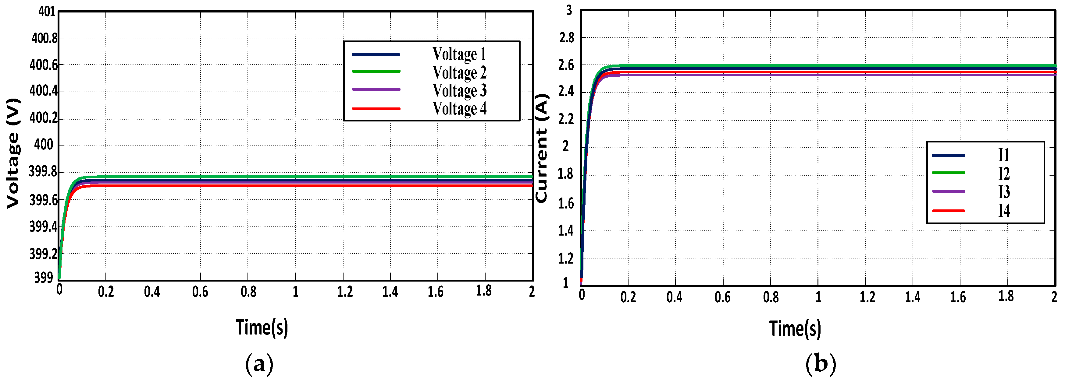
As in the proposed technique, a new local controller with reduced order was developed, which had better phase margin than the existing techniques. With the proposed technique, limitations of the conventional droop control technique can be removed, and better proportional load sharing and voltage regulation can be achieved by a simple control structure. The proposed control technique is more robust and simpler compared to the existing techniques. Simulation results ensured the current-sharing accuracy of the two existing techniques as well as the proposed technique. The simulations results of the two existing techniques are shown in Figure 9 and Figure 10, while the results of the proposed technique are presented in Figure 11. In order to analyze the robustness and disturbance rejection capability of the proposed and the existing techniques, output current disturbance of 10 A with 100 rad/sec was applied to the four-node-based DC microgrid setup.
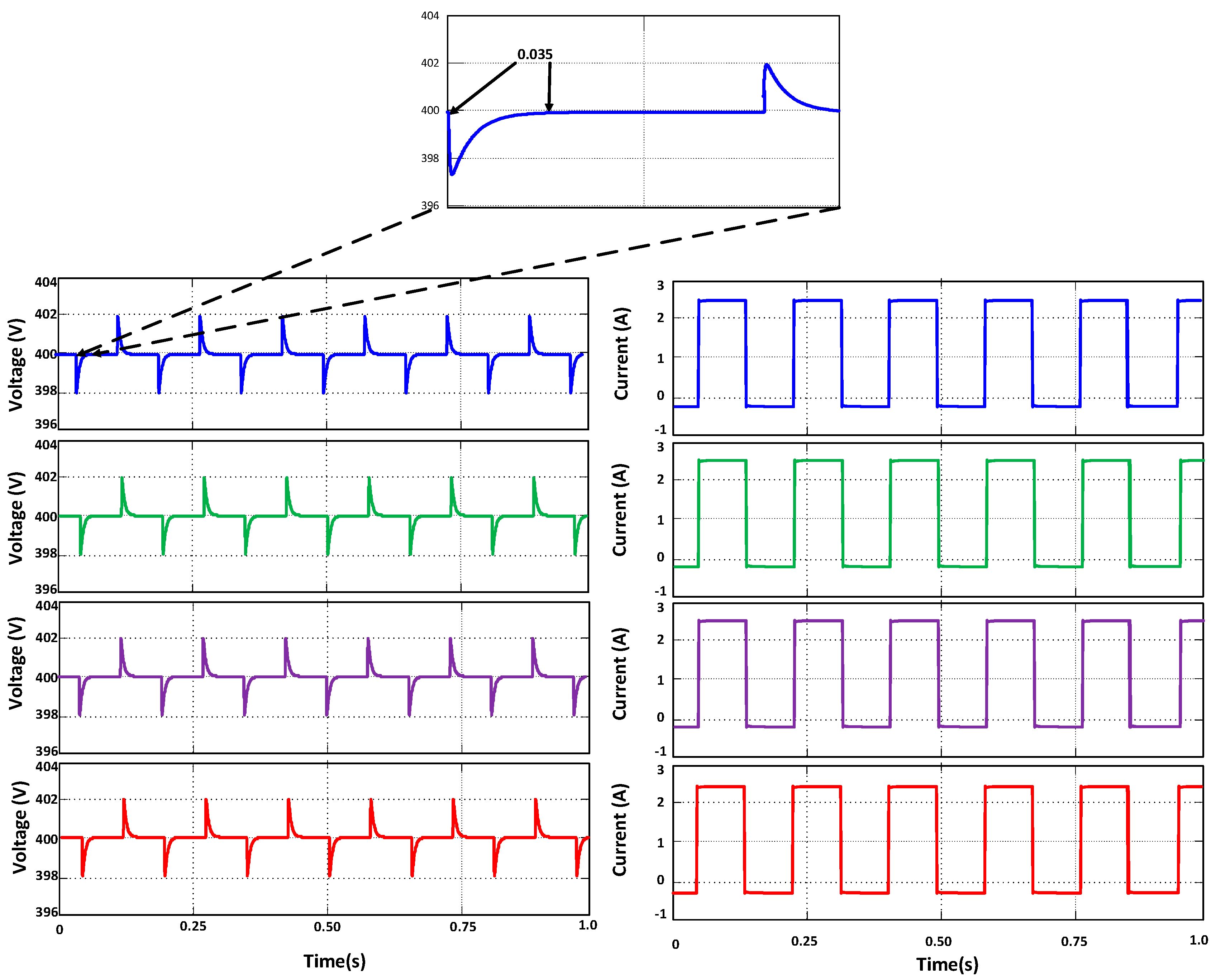
The response of voltage restoration and current sharing of the two existing techniques are shown in Figure 12 and Figure 13, while that for the proposed technique is shown in Figure 14. The convergence time of the conventional droop-control-based technique [12] was 0.07 s, while the convergence time of the other technique [13] was 0.06 s. The disturbance response for the proposed technique is depicted in Figure 14. The convergence time of the proposed technique was 0.035 s which was 50% less than the conventional droop-based controller, while the other controller time was almost 85% of the droop-based technique. In the presence of disturbance, the proposed technique converged to its reference level in very little time, which showed that the finite-gain controller facilitated faster convergence and better robustness to disturbance. Due to the disturbance effect, the current-sharing accuracy of the conventional droop-based controller was affected, while the proposed controller current sharing was better. It was found that the proposed controller response on disturbance was much better than the both recent existing techniques, and the DC microgrid control objectives could be achieved more efficiently with better system stability. Hence, the simulation results confirmed the remarkable performance and superiority of the proposed controller.
7. Conclusions
In this paper, structural improvements have been proposed in the consensus-based cooperative control of DC microgrids to improve the stability, and control performance. The structure of the local controller was reduced, and a droop-less controller was developed. A finite-gain controller was employed in the voltage loop to achieve droop-like performance with a simple proportional controller in the current control loop of the DC–DC buck converter. The finite-gain controller had significant overshoot due to which the system could achieve the desired objectives with a faster response. In the consensus-based cooperative control, a different method was adopted to calculate the average voltage and current difference. Only single voltage correction term was enough to achieve relative current sharing and DC voltage regulation. Small signal analysis was carried out to demonstrate the stability and control performance of the proposed technique. The stability plots for the proposed technique confirmed the better control performance of the technique due to its better phase performance. The proposed controller also offered better disturbance rejection capability. The finite-gain-based local controller offered faster convergence and better system robustness in presence of disturbance. The disturbance rejection time of the proposed technique was almost 50% less than the conventional droop-control-based technique. Moreover, communication delay impact on system control performance was considered, and a comparison was made of the voltage control bandwidth. It has been found that the voltage control bandwidth of the proposed technique was much higher than the two existing techniques. A comparison of the voltage control bandwidth with increasing number of nodes showed that the proposed controller was more robust with increasing number of nodes and had higher scalability than the existing techniques. The key benefits of the proposed technique are the simple structure without droop, better stability, higher expandability, and lower cost. Simulation studies in MATLAB/Simulink with comprehensive comparison demonstrated the effectiveness and superiority of the proposed controller.
Author Contributions
M.A.M. proposed the idea for writing the manuscript and did the simulation work. M.M.K. and X.F. suggested the literature and supervised the simulation studies. M.U.S. helped in system designing parameters. M.T.F. helped in formatting and writing.
Funding
This research received no external funding.
Conflicts of Interest
The authors declare no conflict of interest.
References
- Bevrani, H.; Francois, B.; Ise, T. Microgrid Dynamics and Control; John Wiley & Sons: Hoboken, NJ, USA, 2017. [Google Scholar]
- Pogaku, N.; Prodanovic, M.; Green, T.C. Modeling, Analysis and Testing of Autonomous Operation of an Inverter-Based Microgrid. IEEE Trans. Power Electron. 2007, 22, 613–625. [Google Scholar] [CrossRef]
- Li, Y.W.; Kao, C.-N. An Accurate Power Control Strategy for Power-Electronics-Interfaced Distributed Generation Units Operating in a Low-Voltage Multibus Microgrid. IEEE Trans. Power Electron. 2009, 24, 2977–2988. [Google Scholar]
- Kaundinya, D.P.; Balachandra, P.; Ravindranath, N.H. Grid-Connected Versus Stand-alone Energy System decentralized Power-A Review of Literature. Renew. Sustain. Energy Rev. 2009, 13, 2041–2050. [Google Scholar] [CrossRef]
- Xu, L.; Chen, D. Control and operation of a DC microgrid with variable generation and energy storage. IEEE Trans. Power Deliv. 2011, 26, 2513–2522. [Google Scholar] [CrossRef]
- Kakigano, H.; Miura, Y.; Ise, T. Distribution voltage control for DC microgrids using fuzzy control and gain-scheduling technique. IEEE Trans. Power Electron. 2013, 28, 2246–2258. [Google Scholar] [CrossRef]
- Jiang, Z.; Yu, X. Hybrid DC- and AC-linked microgrids: Towards integration of distributed energy resources. In Proceedings of the 2008 IEEE Energy 2030 Conference, Atlanta, GA, USA, 17–18 November 2008; pp. 1–8. [Google Scholar]
- Chen, Y.K.; Wu, Y.C.; Song, C.C.; Chen, Y.S. Design and implementation of energy management system with fuzzy control for DC microgrid systems. IEEE Trans. Power Electron. 2013, 28, 1563–1570. [Google Scholar] [CrossRef]
- Chakraborty, P.; Baeyens, E.; Khargonekar, P.P. Distributed control of flexible demand using proportional allocation mechanism in a smart grid: Game theoretic interaction and price of anarchy. Sustain. Energy Grids Netw. 2017, 12, 30–39. [Google Scholar] [CrossRef]
- Anand, S.; Fernandes, B.G.; Guerrero, J.M. Distributed control to ensure proportional load sharing and improve voltage regulation in low-voltage DC microgrids. IEEE Trans. Power Electron. 2013, 28, 1900–1913. [Google Scholar] [CrossRef]
- Nasirian, V.; Member, S.; Moayedi, S.; Member, S.; Davoudi, A.; Lewis, F.L. Distributed Cooperative Control of DC Microgrids. IEEE Trans. Power Electron. 2015, 30, 2288–2303. [Google Scholar] [CrossRef]
- Lu, X.; Guerrero, J.M.; Sun, K.; Vasquez, J.C. An improved droop control method for dc microgrids based on low bandwidth communication with dc bus voltage restoration and enhanced current sharing accuracy. IEEE Trans. Power Electron. 2014, 29, 1800–1812. [Google Scholar] [CrossRef]
- Yang, Y.; Khan, M.M.; Yu, J. An improved cooperative control method of DC microgrid based on nearest neighbors communication. In Proceedings of the IECON 2017—43rd Annual Conference of the IEEE Industrial Electronics Society, Beijing, China, 29 October–1 November 2017; pp. 792–797. [Google Scholar]
- Pecas Lopes, J.A.; Moreira, C.L.; Madureira, A.G. Defining control strategies for analysing microgrids islanded operation. In Proceedings of the 2005 IEEE Russia Power Tech, St. Petersburg, Russia, 27–30 June 2005; pp. 1–7. [Google Scholar]
- Di Fazio, A.R.; Russo, M.; De Santis, M. Zoning Evaluation for Voltage Optimization in Distribution Networks with Distributed Energy Resources. Energies 2019, 12, 390. [Google Scholar] [CrossRef]
- Li, C.; Yu, X.; Yu, W.; Huang, T.; Liu, Z.-W. Distributed event-triggered scheme for economic dispatch in smart grids. IEEE Trans. Ind. Informat. 2016, 12, 1775–1785. [Google Scholar] [CrossRef]
- Ding, L.; Han, Q.L.; Guo, G. Network-based leader-following consensus for distributed multi-agent systems. Automatica 2013, 49, 2281–2286. [Google Scholar] [CrossRef]
- Kounev, V.; Tipper, D.; Grainger, B.M.; Reed, G. Analysis of an offshore medium voltage DC microgrid environment—Part II: Communication network architecture. In Proceedings of the 2014 IEEE PES T&D Conference and Exposition, Chicago, IL, USA, 14–17 April 2014; pp. 1–5. [Google Scholar]
- Qiu, W.; Liang, Z. Practical design considerations of current sharing control for parallel VRM applications. In Proceedings of the Twentieth Annual IEEE Applied Power Electronics Conference and Exposition, APEC 2005, Austin, TX, USA, 6–10 March 2005; Volume 1, pp. 281–286. [Google Scholar]
- Ferreira, R.A.F.; Braga, H.A.C.; Ferreira, A.A.; Barbosa, P.G. Analysis of voltage droop control method for dc microgrids with Simulink: Modelling and simulation. In Proceedings of the 2012 10th IEEE/IAS International Conference on Industry Applications, Fortaleza, Brazil, 5–7 November 2012. [Google Scholar] [CrossRef]
- Lu, X.; Sun, K.; Guerrero, J.M.; Vasquez, J.C.; Huang, L. State-of-charge balance using adaptive droop control for distributed energy storage systems in DC microgrid applications. IEEE Trans. Ind. Electron. 2014, 61, 2804–2815. [Google Scholar] [CrossRef]
- Guerrero, J.M.; Vasquez, J.C.; Matas, J.; de Vicuna, L.G.; Castilla, M. Hierarchical Control of Droop-Controlled AC and DC Microgrids—A General Approach toward Standardization. IEEE Trans. Ind. Electron. 2011, 58, 158–172. [Google Scholar] [CrossRef]
- Anand, S.; Fernandes, B. Steady state performance analysis for load sharing in DC distributed generation system. In Proceedings of the 2011 10th International Conference on Environment and Electrical Engineering, Rome, Italy, 8–11 May 2011; pp. 1–4. [Google Scholar]
- He, J.; Li, Y.W. Analysis, design, and implementation of virtual impedance for power electronics interfaced distributed generation. IEEE Trans. Ind. Appl. 2011, 47, 2525–2538. [Google Scholar] [CrossRef]
- Zhong, Q.C. Robust droop controller for accurate proportional load sharing among inverters operated in parallel. IEEE Trans. Ind. Electron. 2013, 60, 1281–1290. [Google Scholar] [CrossRef]
- Khorsandi, A.; Ashourloo, M.; Mokhtari, H. A Decentralized Control Method for a Low-Voltage DC Microgrid. IEEE Trans. Energy Convers. 2014, 29, 793–801. [Google Scholar] [CrossRef]
- Mohammed, Y.A.I.; El-Saadany, E.F. Adaptive Decentralized Droop Controller to Preserve Power Sharing Stability of Paralleled Inverters in Distributed Generation Microgrids. IEEE Trans. Power Electron. 2008, 23, 2806–2816. [Google Scholar] [CrossRef]
- Zhang, C.K.; Jiang, L.; Wu, Q.H.; He, Y.; Wu, M. Delay-dependent robust load frequency control for time delay power systems. IEEE Trans. Power Syst. 2013, 28, 2192–2201. [Google Scholar] [CrossRef]
- Liu, S.; Wang, X.; Liu, P.X. Impact of Communication Delays on Secondary Frequency Control in an Islanded Microgrid. IEEE Trans. Ind. Electron. 2015, 62, 2021–2031. [Google Scholar] [CrossRef]
- Hu, T.; Khan, M.M.; Xu, K.; Zhou, L.; Rana, A. Design of an input-parallel output-parallel multi-module dc-dc converter using a ring communication structure. J. Power Electron. 2015, 15, 886–898. [Google Scholar] [CrossRef]
- Saber, R.O.; Murray, R.M. Consensus Problems in Networks of Agents with Switching Topology and Time-Delays. IEEE Trans. Autom. Control 2003, 49, 1520–1533. [Google Scholar] [CrossRef]
- Wu, X.; Shen, C.; Iravani, R. A Distributed, Cooperative Frequency and Voltage Control for Microgrids. IEEE Trans. Smart Grid 2018, 9, 2764–2776. [Google Scholar] [CrossRef]
- Zhang, Y.; Xie, L.; Ding, Q. Interactive Control of Coupled Microgrids for Guaranteed System-Wide Small Signal Stability. IEEE Trans. Smart Grid 2016, 7, 1088–1096. [Google Scholar] [CrossRef]
- Arefifar, S.A.; Mohamed, Y.A.R.I.; El-Fouly, T. Optimized multiple microgrid-based clustering of active distribution systems considering communication and control requirements. IEEE Trans. Ind. Electron. 2015, 62, 711–723. [Google Scholar] [CrossRef]
Figure 1.
Conventional droop-based technique [12].
Figure 1.
Conventional droop-based technique [12].
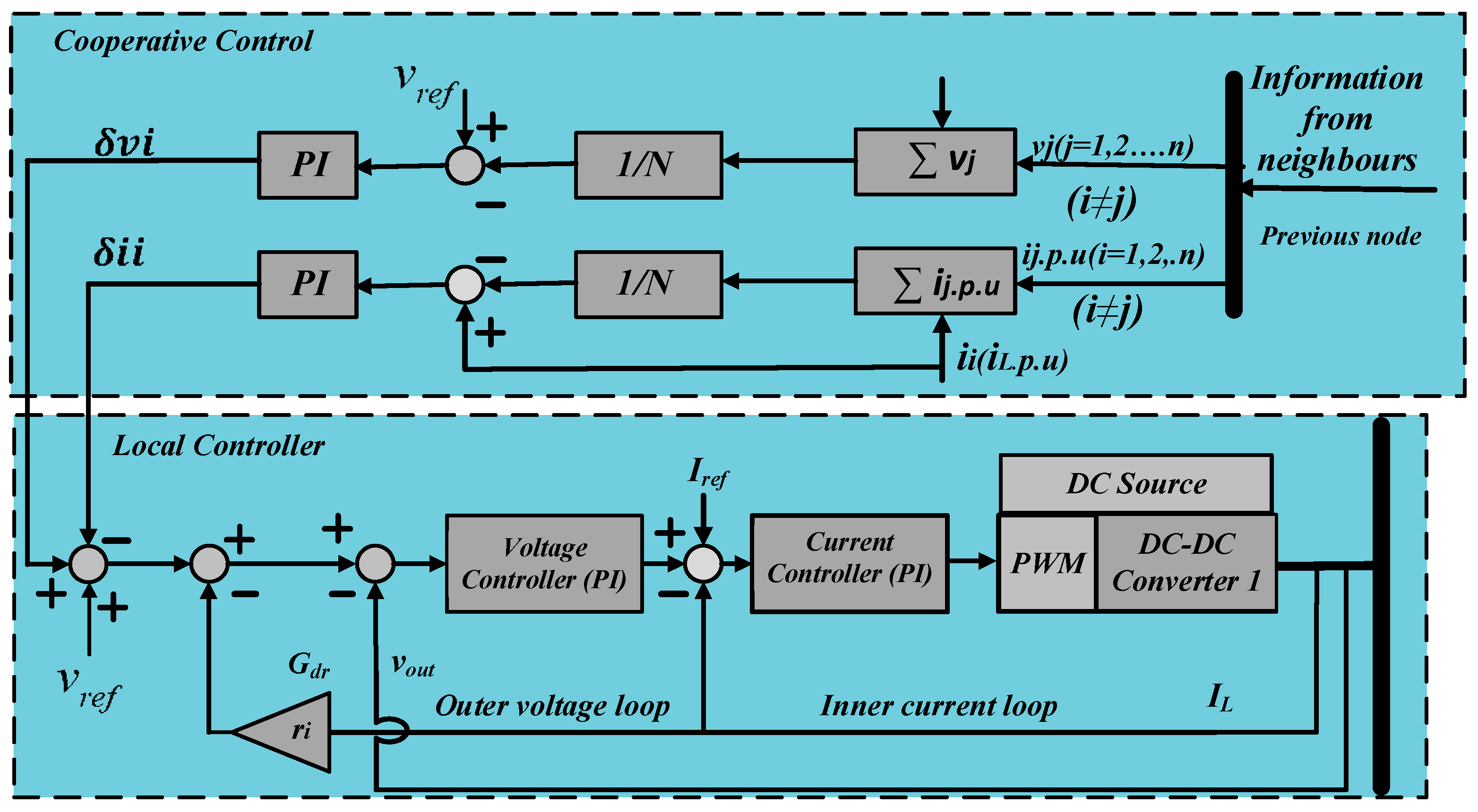
Figure 2.
Local controller of the existing technique [13].
Figure 2.
Local controller of the existing technique [13].

Figure 3.
Proposed local controller with cooperative control structure.

Figure 4.
Dynamic consensus protocol overview. (a) Averaging procedure for a particular node; (b) global averaging procedure in frequency domain.
Figure 4.
Dynamic consensus protocol overview. (a) Averaging procedure for a particular node; (b) global averaging procedure in frequency domain.

Figure 5.
Small signal model of buck converter.
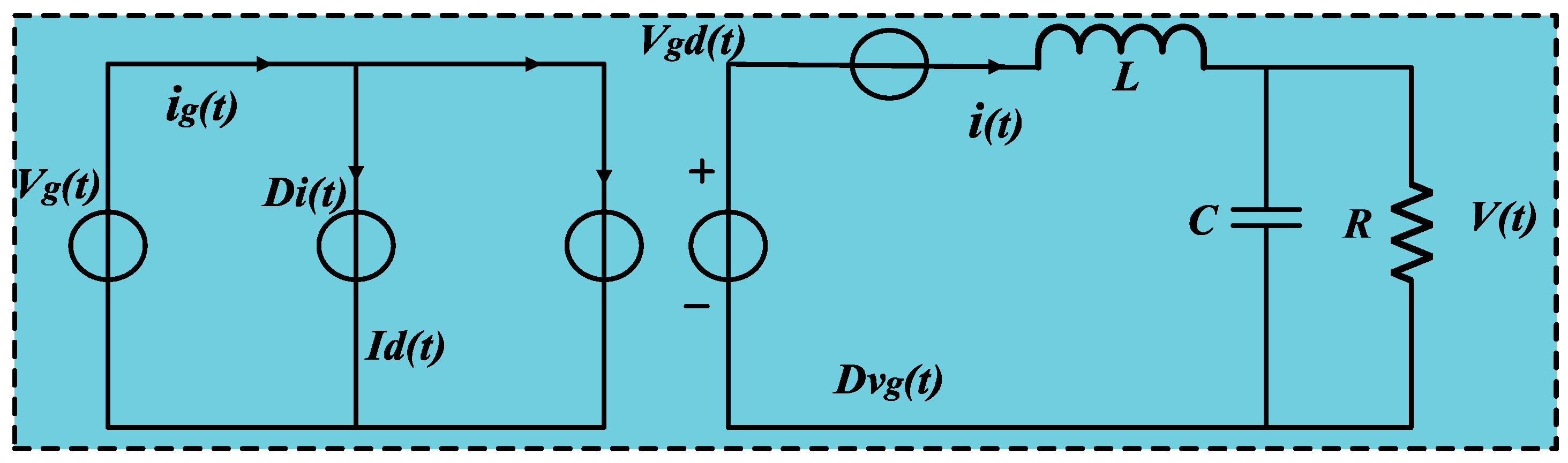
Figure 6.
Small signal models of existing and proposed control techniques: (a) small signal model of droop-based technique [12], (b) small signal model of improved cooperative technique [13], and (c) small signal model of the proposed technique.
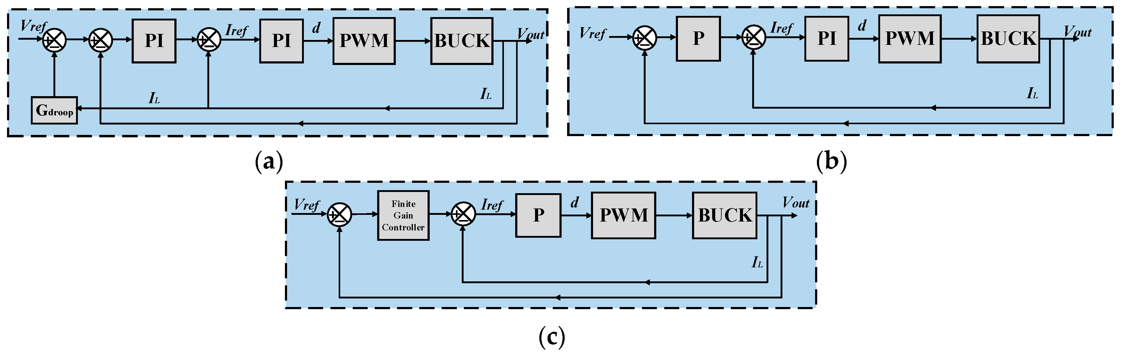
Figure 7.
Bode plot response (a) , (b) .
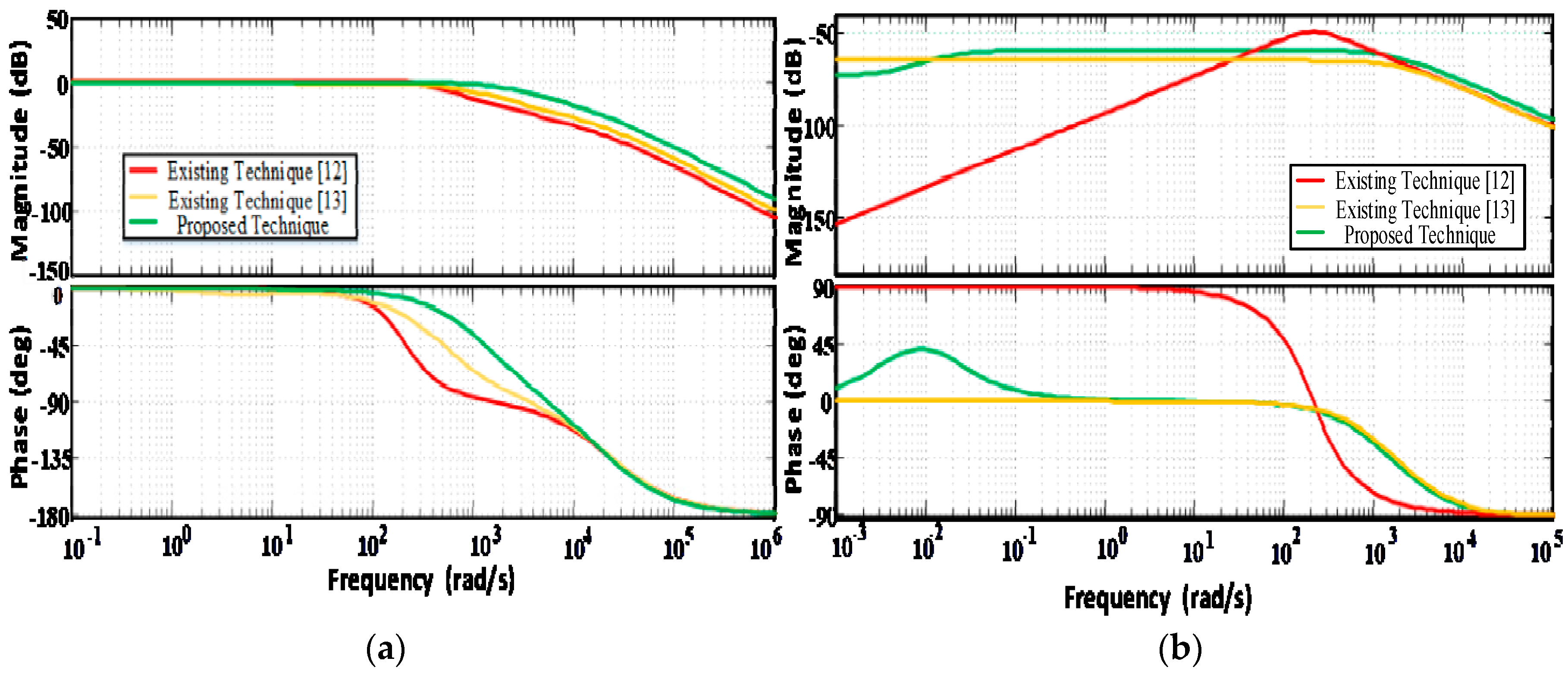
Figure 8.
Communication network spanned across the microgrid to exchange information.

Figure 9.
Existing technique [12] with ring communication structure. (a) Voltage waveform, (b) Current waveforms.
Figure 9.
Existing technique [12] with ring communication structure. (a) Voltage waveform, (b) Current waveforms.
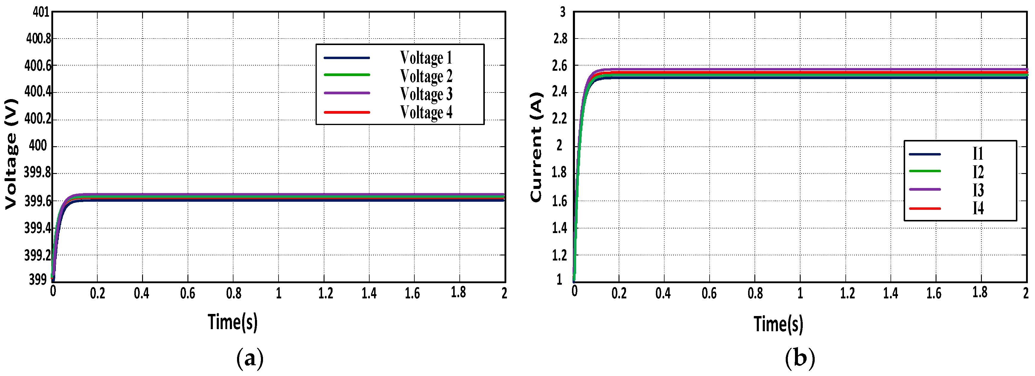
Figure 10.
Existing technique [13] with ring communication structure. (a) Voltage waveform, (b) Current waveforms.
Figure 10.
Existing technique [13] with ring communication structure. (a) Voltage waveform, (b) Current waveforms.

Figure 11.
Proposed technique [12] with ring communication structure. (a) Voltage waveform, (b) Current waveforms.
Figure 11.
Proposed technique [12] with ring communication structure. (a) Voltage waveform, (b) Current waveforms.
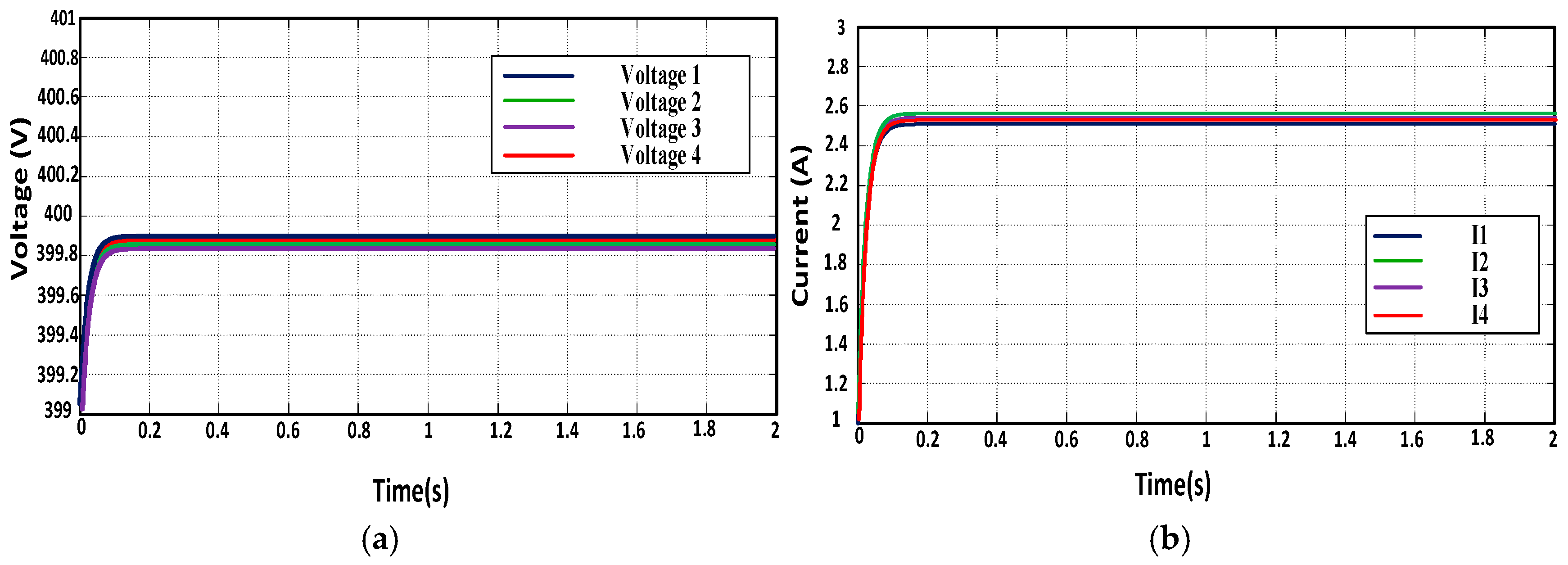
Figure 12.
Current and voltage waveforms response of the existing technique [12] with disturbance signal.
Figure 12.
Current and voltage waveforms response of the existing technique [12] with disturbance signal.

Figure 13.
Current and voltage waveforms response of the existing technique [13] with disturbance signal.
Figure 13.
Current and voltage waveforms response of the existing technique [13] with disturbance signal.

Figure 14.
Current and voltage waveforms response of the proposed technique with disturbance signal.
Figure 14.
Current and voltage waveforms response of the proposed technique with disturbance signal.

Table 1.
Comparison of different power-sharing techniques.
| Power-Sharing Techniques | Stability | Disturbance Rejection Time | Current-Sharing Accuracy | Voltage Regulation | Viability |
|---|---|---|---|---|---|
| Conventional droop-based technique [12] | Low | High | High | High | Low |
| Improved cooperative control technique [13] | Medium | Medium | High | Medium | Medium |
| Proposed technique | High | Low | High | High | High |
Table 2.
Voltage control bandwidth comparison for a four-node system using communication delay and with increasing number of nodes.
Table 2.
Voltage control bandwidth comparison for a four-node system using communication delay and with increasing number of nodes.
| Communication Delay | Existing Technique [12], Voltage Control Bandwidth | Existing Technique [13], Voltage Control Bandwidth | Proposed Technique, Voltage Control Bandwidth |
|---|---|---|---|
| 0.1 ms | 0.507 kHz | 0.528 kHz | 0.550 kHz |
| 0.05 ms | 0.520 kHz | 0.540 kHz | 0.562 kHz |
| 0.33 ms | 0.525 kHz | 0.546 kHz | 0.568 kHz |
| 0.40 ms | 0.528 kHz | 0.548 kHz | 0.570 kHz |
| Number of nodes | Bandwidth with increasing nodes | Bandwidth with increasing nodes | Bandwidth with increasing nodes |
| 5 | 0.520 kHz | 0.540 kHz | 0.562 kHz |
| 10 | 0.270 kHz | 0.295 kHz | 0.320 kHz |
| 20 | 0.145 Hz | 0.170 kHz | 0.205 kHz |
Table 3.
System design parameters.
| Parameters | Existing Technique [12] | Existing Technique [13] | Proposed Technique | |
|---|---|---|---|---|
| PV/Wind | Vg | 600 V | 600 V | 600 V |
| Reference voltage | Vref | 400 V | 400 V | 400 V |
| DC/DC Buck converter | L | 2.5 mH | 2.5 mH | 2.5 mH |
| C | 220 μF | 220 μF | 220 μF | |
| Inner loop | kp | 0.1 | 0.1 | 0.09 |
| ks | 0.5 | 0.5 | — | |
| Outer loop | kp | 0.05 | 0.2 | — |
| ks | 10 | — | — | |
| z | — | — | 0.045 | |
| p | — | — | 0.0045 | |
| Droop gain | Gd | 0.025 | — | — |
| Distributed cooperative control | kpc,v | 1.7 | 10 | 25 |
| ksc,v | 15 | 200 | 150 | |
| kpc,i | 1.5 | — | — | |
| ksc,i | 2.5 | — | — |
© 2019 by the authors. Licensee MDPI, Basel, Switzerland. This article is an open access article distributed under the terms and conditions of the Creative Commons Attribution (CC BY) license (http://creativecommons.org/licenses/by/4.0/).
Share and Cite
MDPI and ACS Style
Mumtaz, M.A.; Khan, M.M.; Fang, X.; Shahid, M.U.; Faiz, M.T. Structural Improvements in Consensus-Based Cooperative Control of DC Microgrids. Electronics 2019, 8, 187. https://doi.org/10.3390/electronics8020187
AMA Style
Mumtaz MA, Khan MM, Fang X, Shahid MU, Faiz MT. Structural Improvements in Consensus-Based Cooperative Control of DC Microgrids. Electronics. 2019; 8(2):187. https://doi.org/10.3390/electronics8020187
Chicago/Turabian StyleMumtaz, Muhammad Adnan, Muhammad Mansoor Khan, Xiangzhong Fang, Muhammad Umair Shahid, and Muhammad Talib Faiz. 2019. "Structural Improvements in Consensus-Based Cooperative Control of DC Microgrids" Electronics 8, no. 2: 187. https://doi.org/10.3390/electronics8020187
Note that from the first issue of 2016, this journal uses article numbers instead of page numbers. See further details here.