
UAV-Assisted Cooperative NOMA and OFDM Communication Systems: Analysis and Optimization


Department of Electronic Engineering, Hanoi University of Industry, Cau Dien Street, Bac Tu Liem District, Hanoi 100000, Vietnam
*
Author to whom correspondence should be addressed.
†
These authors contributed equally to this work.
J. Sens. Actuator Netw. 2024, 13(1), 18; https://doi.org/10.3390/jsan13010018
Submission received: 13 December 2023
/
Revised: 25 January 2024
/
Accepted: 14 February 2024
/
Published: 19 February 2024
Abstract
:Utilizing unmanned aerial vehicles (UAVs) to facilitate wireless communication has emerged as a viable and promising strategy to enhance current and prospective wireless systems. This approach offers many advantages by establishing line-of-sight connections, optimizing operational efficiency, and enabling flexible deployment capabilities in various terrains. Thus, in this paper, we investigate UAV communication in a relaying network in which a UAV helps communication between a source and two destination users while flying to a location. To have a complete view of our proposed system, we consider both orthogonal multiple access, such as OFDMs and non-orthogonal multiple access (NOMA) scenarios. Moreover, we apply successive convex optimization (SCO) and the block-coordinate gradient descent (BCGD) for the sum-rate optimization problems to improve the system performance under constraints of total bandwidth and total power at the ground base station and UAV. The experimental results validate that the achievable secrecy rates are notably enhanced using our proposed algorithms and show optimal trends for critical parameters, such as transmit powers, the flight trajectory and speed of the UAV, and resource allocation of OFDM and NOMA.
1. Introduction
Over the past decade, unmanned aerial vehicles (UAVs), with their advantages of high mobility, low cost, and rapid deployment, have been used in diverse applications, including surveillance, rescue, cargo transport, and data collection in wireless sensor networks [1,2]. The research community is highly interested in the newest emerging application of UAVs, that is, UAV-assisted wireless communication (UAVWC). Communication with the support of UAVs is an effective wireless network deployment solution for future communication models, specifically for 6G network systems [3]. Unlike terrestrial wireless networks, where the wireless channel undergoes multi-path fading, UAVWC can provide line-of-sight connections to wireless devices by using aerial base stations; hence, UAVWC is expected to have a higher performance than existing terrestrial wireless systems. Moreover, the mobility and flexibility of UAVs allow UAVWC to operate with broader coverage or in dangerous areas that require high deployment and maintenance costs for the base stations. To exploit the great benefits of UAVWC, many recent studies on wireless communication have carried out a lot of work to solve technical challenges and optimize the performance of UAVWC [4,5,6].
Furthermore, UAVs have gained extensive utilization within wireless sensor networks. As mobile access points or base stations, UAVs present a promising resolution to address the substantial storage demands prevalent in wireless sensor networks [2,7]. By facilitating UAV-assisted data aggregation from numerous sensor nodes equipped with wireless capabilities, the singular-antenna UAV empowers all sensor nodes within its coverage scope to transmit data. Consequently, these sensor nodes relay their collected information back to the UAV. Given the significant implications identified, there exists an imperative necessity to delve into research regarding the NOMA–UAV model. Thus, the model communication of the NOMA/OFDM–UAV combination can significantly enhance the performance of wireless networks in a broader context and specifically contribute to advancing wireless sensor networks. Consequently, greater attention and scrutiny are warranted to comprehensively explore the NOMA/OFDM–UAV model’s capabilities and implications.
1.1. Related Work
To optimize the performance of UAVWC and exploit its benefits, recent studies on wireless communication have worked on overcoming various technical challenges. In [8], the authors examined and provided statistical models for an air-to-ground radio frequency (RF) channel in a dense urban environment, then air-to-ground RF statistical models for different conditions were investigated in [9]. These results allow network designers to make easier planning and performance evaluations for WN-aNWs. The studies of UAVWC can be classified into two groups, one using UAVs as static aerial transceivers and another exploiting the mobility of UAVs, known as static and mobile UAVWCs, respectively. Moreover, in [10], the authors proposed a UAV deployment algorithm to minimize the number of UAVs needed to provide wireless coverage for a given area. In [11], the authors solved the uplink sum-rate maximization problem of a static wireless-powered UAVWC. The authors in [12] optimized the UAV’s location and user association for UAV-assisted mobile networks, with the goal of making the traffic loads of UAVs almost equal so that the networks can be stable. In [13], the authors considered a low-altitude aerial platform (LAP) for the urban environment and provided a mathematical model of the altitude and wireless coverage, allowing network designers to predict the optimum altitude of the static UAVWC.
NOMA has been evaluated as a potential solution for future networks, such as beyond fifth-generation (B5G) and sixth-generation (6G) networks, because its benefits can meet the new 6G performance requirement, especially for huge connectivity [14,15,16,17]. NOMA is a multiple-access technique that facilitates concurrent sharing of identical frequency and temporal resources among users [18]. This is achieved by means of power domain multiplexing, wherein users are assigned distinct power levels, contingent upon their respective channel conditions, thereby enabling users with weaker signal strengths to utilize the shared resources alongside stronger signal counterparts concurrently. On the other hand, orthogonal frequency division multiple access (OFDMA) is a modulation and multiplexing technique employed in transmitting data across communication channels. OFDMA partitions the available frequency spectrum into multiple orthogonal subcarriers, facilitating simultaneous and parallel data transmission [19]. Thus, many publications have investigated the application of NOMA for UAV networks. Notably, the authors in [20] outlined new opportunities and challenges with NOMA with the assistance of UAVs in more significant rate regions, balanced performance between system throughput and fairness, and reduced delay. In [21], the authors evaluated the outage probability of UAV-aided non-orthogonal multiple access (NOMA) networks and uplink and downlink transmissions. In [22], the authors analyzed a UAV-aided device-to-device network’s sum rate and average coverage probability for both static and mobile UAV scenarios. Moreover, the authors in [23] investigated the delay-constrained performance analysis of a multi-antenna-assisted multiuser NOMA-based spectrum sharing system and examined the sum effective rate for the downlink NOMA system. The work in [24] solved the problem of improving the secrecy performance in UAV-assisted NOMA communication by jointly optimizing the UAV’s trajectory and the transmit powers of legitimate users. A UAV-enabled space–air–ground integrated relay system applying the NOMA technique is presented in [25]. In this publication, the authors summarized the UAV–ground NOMA communication into a max–min problem regarding UAV’s energy efficiency. The use of artificial intelligence-driven UAV–NOMA to improve the quality of experiences of terrestrial multi-users is studied in the works [26,27]. Moreover, the authors in [28] investigated the UAV in PD-NOMA with concurrent uplink transmission of the aerial user (AU) and terrestrial user (TU). To enhance the achievable data rate of both AU and TU, these authors developed an analytical framework to calculate the probability of rate coverage; the results showed that the min-height of the AUE is contingent upon its distance from the BS as it follows a designated trajectory. This underscores the significance of accurately modeling the AUE trajectory within cellular-connected UAV systems. In [29], a heuristic algorithm and logarithmic approximation are applied to solve the problem of the total energy efficiency for UAV communication in a downlink NOMA network. In summary, these related works exploring UAV facilitating NOMA communication are delineated in Table 1, presented below.
1.2. Main Contributions
As the analysis has shown above, specifically in Table 1, the studies of UAV flight trajectory, its influence, and transmitted power allocation to the NOMA–UAV network using mathematical methods are limited. Therefore, in this paper, we investigated a UAV relaying system including two users, a near user and a far user. The UAV’s flight path is from a beginning position to an ending position, and it assists in communication between a ground base station (GBS) and two destination users (DUs). Two multiple access techniques, orthogonal frequency division multiple access (OFDMA), in which the frequency resource is split for each user, and non-orthogonal multiple access (NOMA), in which the user’s signals are transmitted on the same frequency resource with different power levels, are examined. The contributions of our work are encapsulated as follows:
- We have proposed a model for leveraging UAV-assisted ground communication in specialized communication scenarios where data stations are deployed in complex terrains without direct connectivity to the base station. Our objective is to devise optimal algorithms for the operation of UAVs and ground stations to achieve the maximum system capacity for two scenarios employing NOMA and OFDMA, under constraints of energy, travelling time of the UAV, and required total data from further users;
- We formulated optimization problems to maximize the system sum data rate for both NOMA and OFDMA scenarios. Since these problems are not convex, we transformed them into equivalent forms that can be readily solved using block-coordinate gradient descent (BCGD) and successive convex optimization (SCO) techniques to find the optimal parameter set. We demonstrated that our proposed algorithm guarantees convergence and significantly improves the system sum data rate metric.
The remainder of this article is arranged as follows. The system model and preliminary results for OFDMA-/NOMA-based UAV relaying (OFDMA–/NOMA–UAVR) protocols are described in Section 2. The problem formulation and solution for the sum-rate maximization for OFDMA–/NOMA–UAVR protocols are presented in Section 3. The overall algorithm and convergence analysis are presented in Section 4. The simulation results and discussion are presented in Section 5. Finally, the conclusions are presented in Section 6.
2. System Model
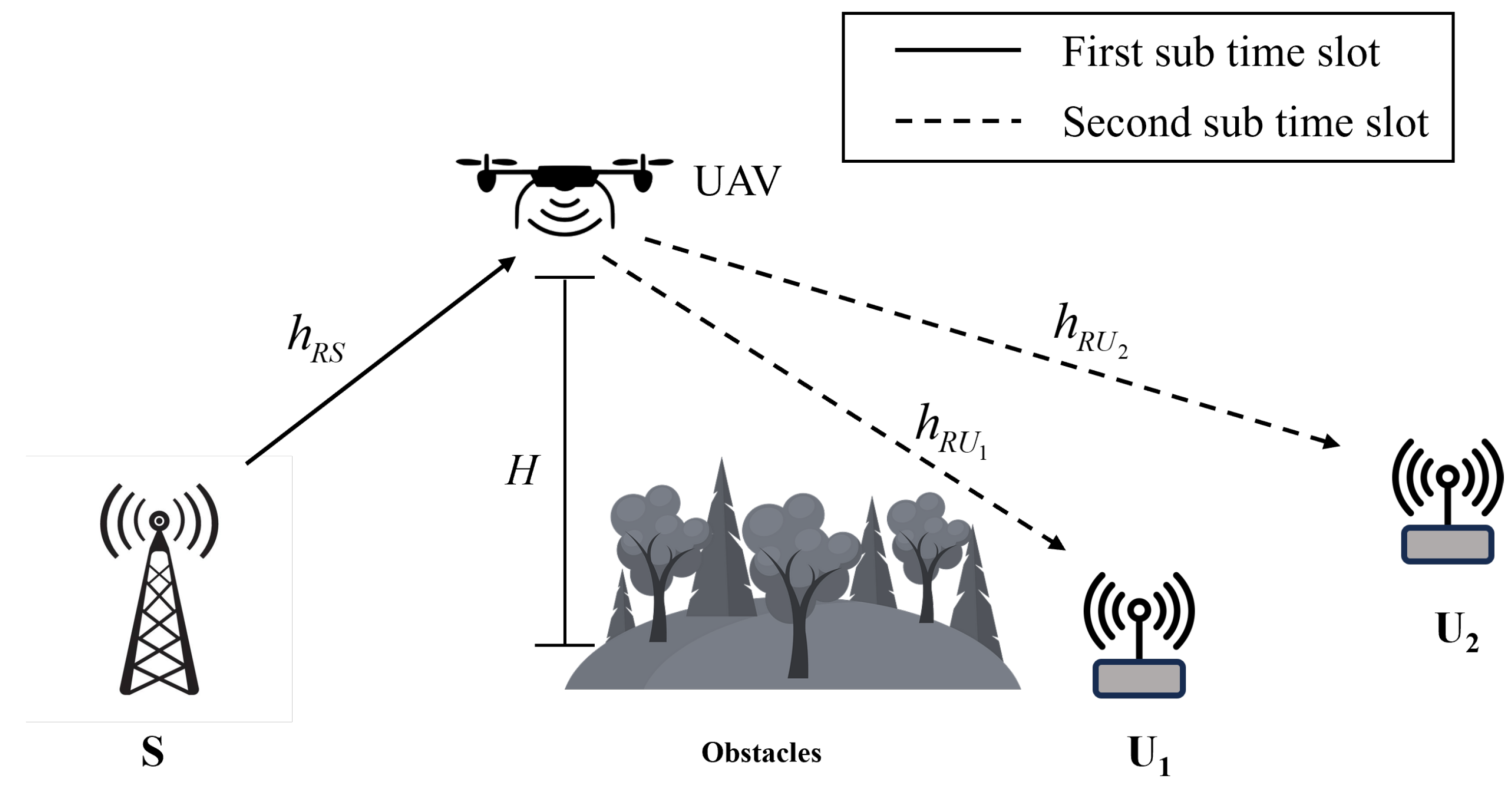
We consider a UAV relaying system, as illustrated in Figure 1, in which a UAV, R, flies at a fixed altitude H from an initial location to a final location , and helps a source S communicate with two users. Due to the utilization of the same decoding approach by SIC receivers in NOMA for the signals of closer users, research on NOMA typically investigates the 2-user model, consisting of a closer user and a further user. Furthermore, the receivers in OFDMA decode the received signal in a similar manner. As a result, our study concentrates on a UAV-assisted cooperative communication scheme for the 2-user scenario, aiming to minimize mathematical complexity while maintaining the overarching objective of the optimization problem. Nonetheless, the obtained results can be easily extended to scenarios involving multiple users, i.e., a closer user and a further user . S, , and are terrestrial single-antenna nodes. R uses the decode-and-forward (DF) protocol and the half-duplex mode to assist the communication. As R operates in half-duplex mode, each transmission time slot is divided into two sub-time slots. Two multiple access techniques, specifically, OFDMA and NOMA, are investigated in this study. The transmission in each sub-time slot for the OFDMA-based UAV relaying (OFDMA–UAVR) and NOMA-based UAV relaying (NOMA–UAVR) is illustrated in Figure 2. We assume that (i) there is no direct link between S and users because of obstacles; (ii) the relay’s operation is over a length of time T; (iii) the UAV takeoff and landing are not considered, and we concentrate on the UAV operation period and altitude H; (iv) since is located far from S, it necessitates the system to provide a minimum required sum rate, ; and (v) T is split into N equal time slots , where is adequately small, such that the position of the UAV can be determined as a constant during . Finally, in this paper, system variables for this system model are summarized in Table 2.
The horizontal positions of S, , , and R during are represented by , , , and , respectively. The channel gain from R to a ground source node X, during is given by
Here, is the channel gain at (m).
3. Preliminary Results and Sum-Rate Optimization Problem Formulation
3.1. Preliminary Results
In this subsection, the signal transmission equations between S, R, , and are presented. Subsequently, the data rate expressions for each user’s signal are established. The results for the OFDMA-based UAV relaying (OFDMA—UAVR) and NOMA-based UAV relaying (NOMA–UAVR) schemes are presented as follows.
3.1.1. OFDMA-Based UAV Relaying Protocol
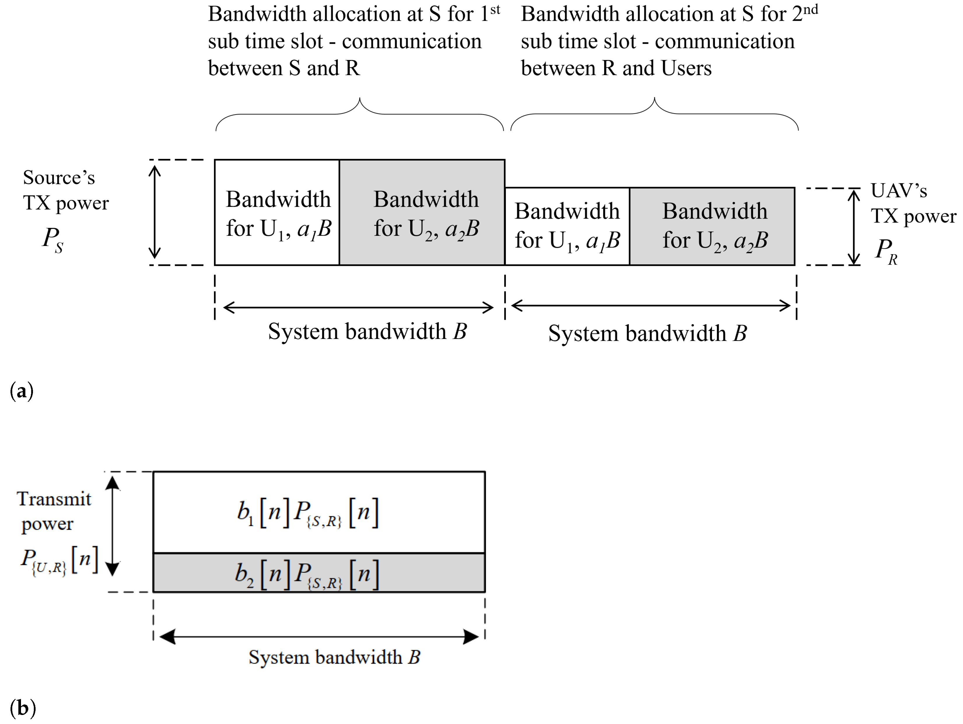
S transmits the signals in the initial sub-time slot within that are and , with the power on the bandwidths , and , respectively, where B is the system bandwidth, is the bandwidth allocation factor of OFDMA and satisfies both and , with as the smallest value of . The received signal and instantaneous rate at R are given by
where is the additive white Gaussian noise (AWGN) at R.
During the following sub-time slot within , the relay node will forward and to and , respectively, on their corresponding bandwidths. The received signal and instantaneous rate at are given by
where is the transmitted power of node R and is AWGN at .
Due to the R node acting as the DF relay, the end-to-end instantaneous rate of for guaranteeing successful decoding at is given by
3.1.2. NOMA-Based UAV Relaying Protocol
In the initial sub-time slot within , S broadcasts the superimposed signals, and , with the powers and , respectively, on bandwidth B, where is the power allocation factor of NOMA and satisfies both and , with as the smallest value of . The received signal at R node can be expressed as
Using SIC (successive interference cancellation), R decodes first and then eliminates from the received signal before decoding . The instantaneous rates of and for guaranteeing successful decoding at R are given by
In the second sub-interval slot within , node R will forward and with the powers and , respectively, on bandwidth B. The received signal at is given by
At , SIC is employed to decode before decoding . The instantaneous rates of and for guaranteeing successful decoding at are given by
The instantaneous rate of at is given by
Since R is the DF relay, the end-to-end instantaneous rate of for guaranteeing successful decoding at is given by
3.2. Sum-Rate Optimization Problem Formulation
In this section, we utilize the findings from Section 3.1 to formulate the optimization problem of maximizing the sum data rate for both the OFDMA–UAVR and NOMA–UAVR schemes under the constraint of achieving the required sum rate at , the power budgets, the trajectory of UAV, and the resource allocation factors.
Letting and denote the power budget and maximum transmit power during of node , we have the following inequalities:
With the above assumptions from Section 2, the constraints of the UAV trajectory or of R are expressed as
Next, letting , , , , and , the issues related to maximizing the sum-rate of our proposed system for both the OFDMA–UAVR and NOMA–UAVR protocols are, respectively, formulated as in (22) and (23), shown at the top of the page.
For the NOMA–UAVR protocol, the SIC of must decode before trying to detect the signal ; hence, the constraint in Equation (23d) is the condition for successfully decoding at , which allows the SIC at to operate correctly.
4. Proposed Alternative Optimization Problem
In Section 3, we have presented the formulation of the sum data rate optimization problem for the considered system. However, it is important to note that the objective functions in (22a) and (23a) are neither convex nor concave. Therefore, (P1) and (P2) are not in the form of convex optimization problems and cannot be solved using convex optimization tools such as CVX. For that reason, we propose alternative solutions that allow us to tackle these non-convex problems using the BCGD and SCO approaches. In particular, we apply the BCGD approach to optimize individual variable blocks of (P1) and (P2) while maintaining the other variable blocks unchanged. For a given resource allocation factor (or ) and transmit powers , we optimize the trajectory of R, (defined as (P1.1) and (P2.1) for the OFDMA–UAVR and NOMA–UAVR protocols, respectively). For a given UAV’s trajectory and (or ), we optimize the transmit powers (defined as (P1.2) and (P2.2) for the OFDMA–UAVR and NOMA–UAVR protocols, respectively). Finally, for a given and , we optimize for the OFDMA–UAVR protocol (defined as (P1.3)) and for the NOMA–UAVR protocol (defined as (P2.3)). The non-convex objective functions are addressed by applying the SCO method. Ultimately, we introduce the comprehensive algorithms and prove the convergence behaviour of these proposed methods.
4.1. UAV Trajectory Optimization (TO)
In this subsection, we use the SCO method to optimize the trajectory of R for the OFDMA–UAVR and NOMA–UAVR protocols.
4.1.1. TO in OFDMA-Based UAV Relaying Protocol
It is seen that, although (24) and (25) lack convexity concerning , they exhibit convexity in relation to and , respectively. This attribute allows us to derive lower bounds for and that are convex with respect to . Specifically, at a given point (we assume that is the optimal UAV’s flight trajectory obtained after the -th iteration), the following lower bounds can be obtained using the first-order Taylor expansion [17]:
where and are given by
4.1.2. TO in NOMA-Based UAV Relaying Protocol
Following the similar approach as in Section 4.1.1, we can obtain the following inequalities using the first-order Taylor expansion:
where , and are given in (37), shown below:
4.2. Transmit Power Optimization (TPO)
In this subsection, we optimize the transmit powers of S and R for the OFDMA–UAVR and NOMA–UAVR protocols.
4.2.1. TPO in OFDMA-Based UAV Relaying Protocol
Substituting (6) into (22), at a given and , (P1) can be expressed as (P1.2) (or (41)), shown below:
where , and .
It is seen that (P1.2) represents a convex optimization problem amenable to efficient resolution using standard convex optimization solvers.
4.2.2. TPO in NOMA-Based UAV Relaying Protocol
Let , where and are the optimal transmit powers of S and R, respectively, obtained after the l-th iteration. The application of the first-order Taylor expansion allows us to derive the following inequalities:
where , and are given by
4.3. Optimizing the Resource Allocation (ORA)
In this subsection, we optimize the bandwidth allocation factor and power allocation factor for the OFDMA–UAVR and NOMA–UAVR protocols.
4.3.1. ORA in OFDMA-Based UAV Relaying Protocol
For any given and , (P1) can be rewritten as (P1.3) (or (48)), shown below:
It is seen that (P1.3) is a convex optimization problem that can be efficiently addressed by using conventional convex optimization solvers.
4.3.2. ORA in NOMA-Based UAV Relaying Protocol
5. Proposed Comprehensive Algorithm
In this section, we present the outline of the overall algorithm, denoted as Algorithm 1, for optimizing the sum rate of the considered system using the BCGD technique and alternative optimization problems formulated in Section 4. Additionally, to satisfy the required sum rate constraint at , an initialization scheme, denoted as Algorithm 2, is designed to find valid initial parameter sets for Algorithm 1.
| Algorithm 1 The Sum-Rate Maximization Algorithm for OFDMA–/NOMA–UAVR Protocols. |
|
| Algorithm 2 The Initialization Scheme for Algorithm 1. |
|
5.1. Overall Algorithm
In this part, we introduce the comprehensive algorithms for obtaining efficient approximate solutions for (P1) and (P2) through utilization of the BCGD method. We also present the outcomes of suboptimal problems, namely, (P1.1), (P1.2), (P1.3), (P2.1), (P2.2) and (P2.3). More precisely, the optimization variables consist of three blocks , where is the resource allocation factor, i.e., for the OFDMA–UAVR protocol and for the NOMA–UAVR protocol. Each block of is optimized via addressing (P1.1), (P1.2), and (P1.3) (or (P2.1), (P2.2), and (P2.3)) correspondingly while fixing the values of the rest blocks. The obtained solution after optimizing each block is updated to correspondingly. This process is repeated until a certain condition is met. The details of this algorithm are summarized in Algorithm 1.
In the following, we show the convergence of Algorithm 1. Let , , , and be, respectively, the objective functions of either (P1), (P1.1), (P1.2), and (P1.3) for the OFDMA–UAVR protocol or of (P2), (P2.1), (P2.2), and (P2.3) for the NOMA–UAVR protocol. First, at any provided point , the subsequent inequalities are derived through the execution of Step (3) in Algorithm 1:
where (a) holds, since the first-order Taylor expansions at (26), (27), (35), and (36) are performed at the point ; (b) holds, since is the optimal solution of (P1.1) (or P(2.1)); and (c) holds, since the objective functions of (P1.1) and (P2.1) are the lower bounds of those in (P1) and (P2), respectively.
Using similar explanations for (P1.2), (P1.3), (P2.2), and (P2.3), the inequalities in (53) and (54) can be proven as follows. At any provided point , we can obtain the following inequalities via Step (4) in Algorithm 1:
Next, at any provided point , we also obtain the following inequalities via Step (5) in Algorithm 1:
Finally, we have
This observation reveals that the objective values of (P1) and (P2) are non-decreasing trends throughout iterations. Furthermore, the optimized values of (P1) and (P2) are finite, ensuring the guaranteed convergence of Algorithm 1.
5.2. Initialization Scheme
In this part, we introduce Algorithm 2, which aims to discover an attainable initial variable block for Algorithm 1. Due to the constraint of the sum data rate of , the key concept behind Algorithm 2, that is, maximizing the sum-rate of for the OFDMA–UAVR and NOMA–UAVR protocols, respectively defined as (P3) and (P4). Note that the values of and are set at their highest values; hence, for the OFDMA–UAVR protocol and for the NOMA–UAVR protocol. If the maximum achievable sum rate with Algorithm 2 surpasses that of , the current optimal flight trajectory and transmit powers are and , respectively; otherwise, (P1) and (P2) are infeasible optimization problems. By modifying (P1) and (P2), we can obtain (P3) and (P4) as
Similarly, the problems in (P3) and (P4) are not convex optimization. Therefore, we have introduced alternative solutions for (P3) and (P4), employing the BCGD and SCO approaches. Concretely, the optimization variables consist of two blocks . Subsequently, the BCGD technique is employed to perform optimization for each of these variable blocks within the context of (P3) (or (P4)), while holding the other variable blocks constant. With transmit powers , we optimize (defined as (P3.1) and (P4.1) for the OFDMA–UAVR and NOMA–UAVR protocols, respectively) and, for a given UAV’s trajectory , we optimize (defined as (P3.2) and (P4.2) for the OFDMA–UAVR and NOMA–UAVR protocols, respectively). The result achieved through the optimization of each block is then adjusted in accordance with . This iteration continues until a specific criterion is satisfied. Furthermore, the objective functions with non-convex characteristics are addressed by applying the SCO technique.
By applying (29) and (40), the optimization problems in (P3.1) and (P4.1) at any given and are, respectively, given by (58) and (59), shown on the previous page.
Using (41) and (47), the optimization problems of (P3.2) and (P4.2) at any given and are, respectively, given by (60) and (61), shown on the previous page.
Ultimately, a summary of Algorithm 2 can be located in Table 2, where is the utmost limit of iterations.
Algorithm 2 begins with an initial flight path of the UAV, which consists of a straight line connecting points and and maintains a constant velocity of , where . Additionally, the initial transmission power settings are established as and .
6. Simulation Results
This section presents numerical findings to validate the effectiveness of our proposed optimization algorithms. The system parameters are set up in our simulations as T = 300 (s), N = 60, , (dB), , , , , (m/s), (m), and . The measured coordinates in meters for , , , , and are, respectively, set as , and .
6.1. UAV’s Fight Trajectory and Velocity Analysis
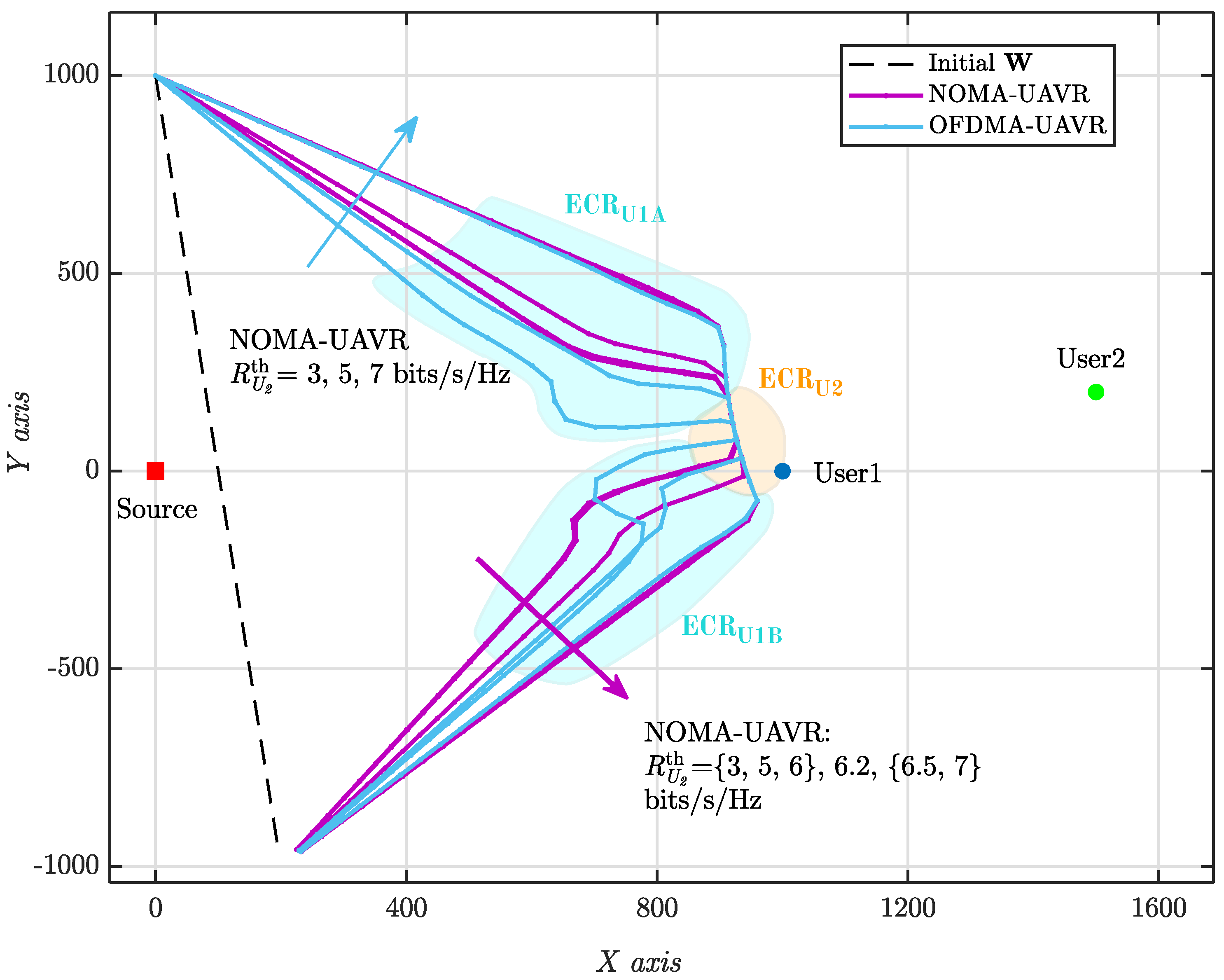
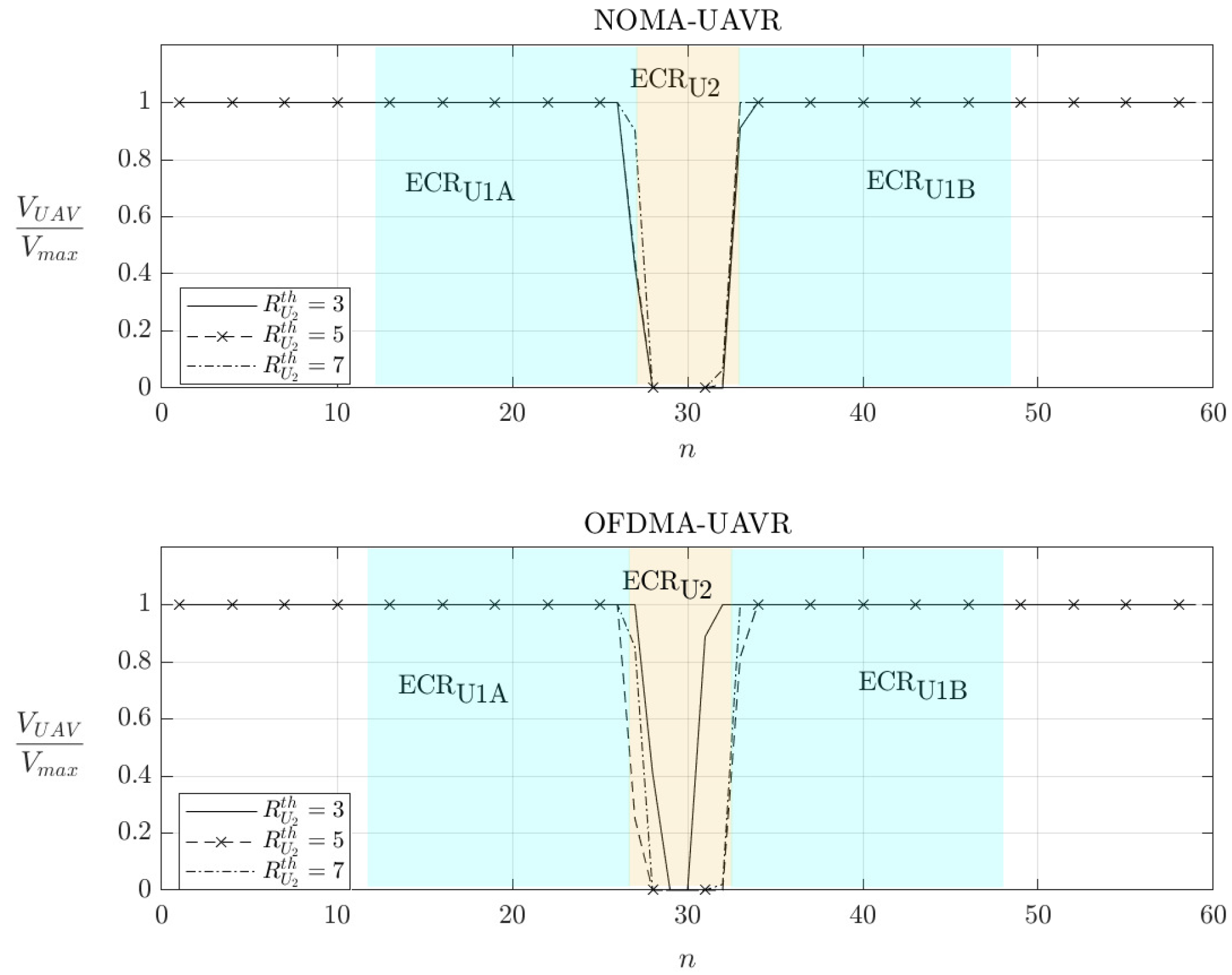
In Figure 3 and Figure 4, we investigate the optimum flight path and velocity of R obtained using the proposed algorithms. The trajectory of R is separated into three phases. During the initial phase (), the positions of R are far from the source and users; this leads to low-efficiency communication. For this reason, during the initial phase, R almost does not forward any information to users and it flies quickly to efficient communication regions (ECRs) where it can assist the commutation at higher data rates. At the second phase, the efficient-communication phase (ECP) , R operates over the two specific ECRs, the , , for providing the good communication and for providing the good communication. and are illustrated in Figure 3. Depending on the configuration of the system, the size of ECRs can be larger or smaller. It is seen that the ECRs are between the source and users that agree with the assessment for the optimum location of the static relay in the conventional relaying systems. As shown in Figure 4, R spends a duration (around ) to stay at to guarantee the required sum rate of , , and also to maximize the system sum rate. When requires more data, i.e., increases, R tends to spend more time at . This can be confirmed using the results for velocity for the case of (bits/s/Hz). For the NOMA–UAVR protocol, the trajectory significantly changes as increases from 6 to 6.5 (bits/s/Hz); otherwise, it almost does not change. For the OFDMA–UAVR protocol, the trajectory substantially changes with the increase in . For high values for , R flies with a similar trajectory in both NOMA–UAVR and OFDMA–UAVR protocols. At the final phase , R stops forwarding the information to users and quickly flies from and/or to the final location.
6.2. Transmission Powers and Resource Allocation Analysis
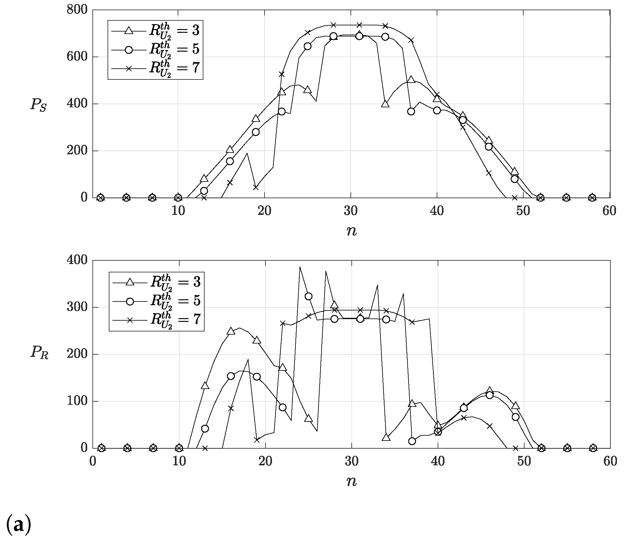
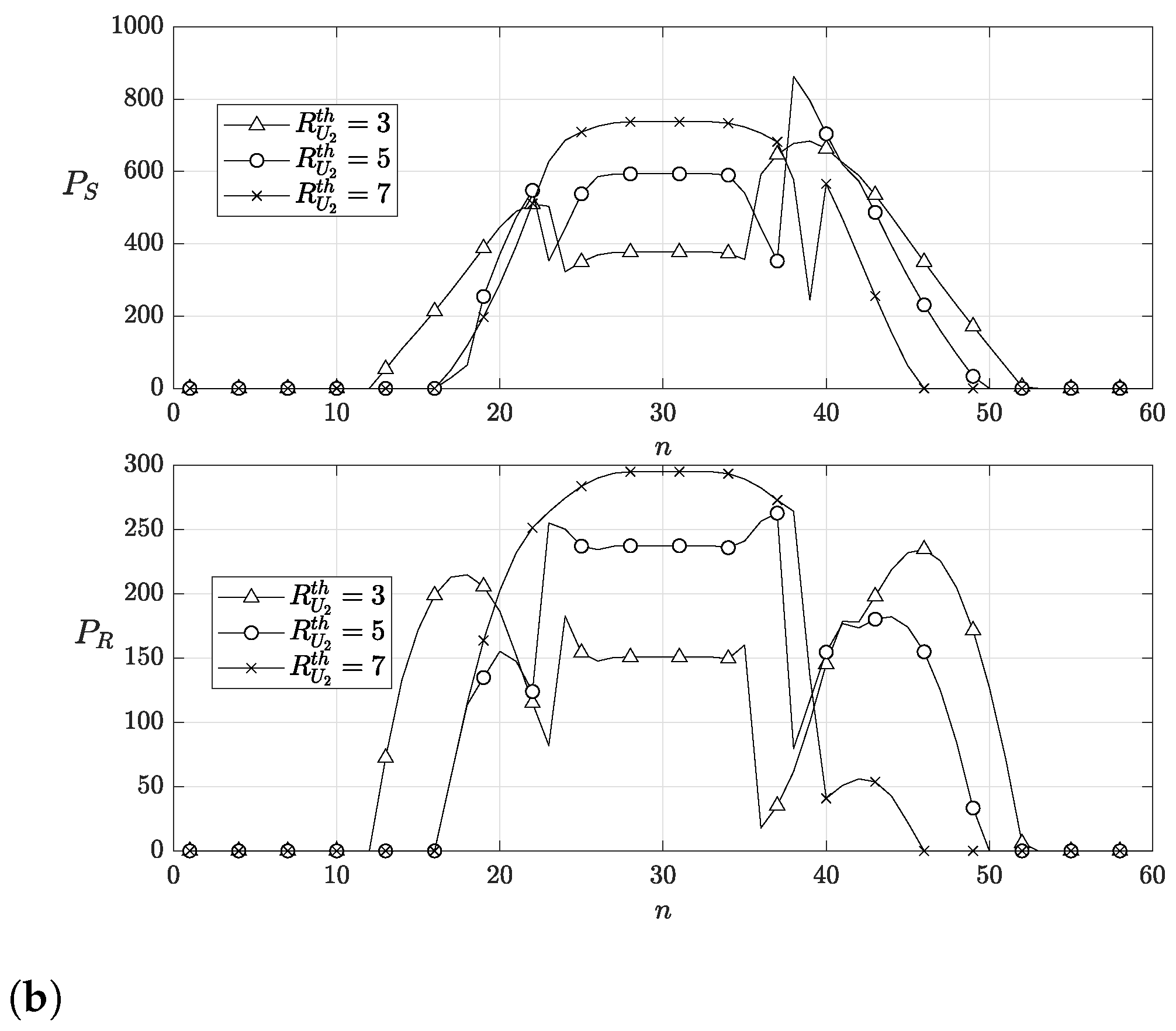
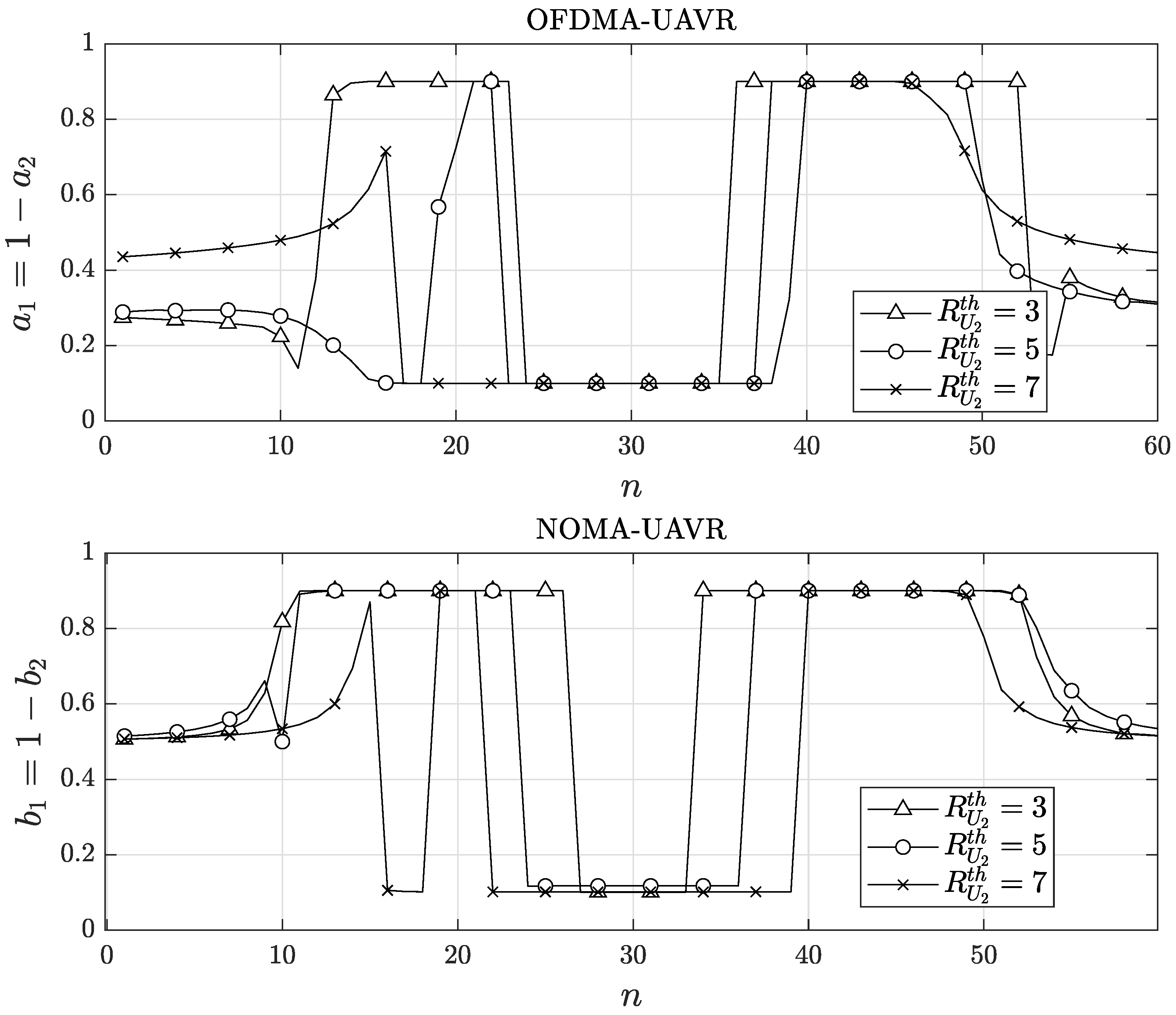
In Figure 5 and Figure 6, we present the optimal transmitted powers and resource allocation elements (i.e., a and b) obtained using the proposed algorithms. In these figures, we focus on the patterns in the transmission power levels, a and b, during the ECP . Particularly, these trends are separated into three sub-phases. During the first sub-phase of the ECP, the transmit powers increase as R flies closer to , then reach a peak and decrease as R flies far away from to transit to . Next, during the second sub-phase of the ECP, the transmits powers increase again as R flies toward to , then they slightly vary as R flies in , and, finally, they decrease as R flies far away from and transits to The trends in the transmit powers in the last sub-phase of the ECP are the opposite trends from the first sub-phase of ECP. Moreover, the trends observed at low values of (e.g., ) are more obvious than those observed at high values (e.g., (bits/s/Hz)). As shown in Figure 6, the general trend of (or ) is receiving high values as R flies near and low values as R flies near . Similarly, we can also explain the trend in (or ) using the effects of the trajectory of R, , and on the instantaneous rates at and .
6.3. Analysis of Instantaneous Rate and Sum Data Rate of Each User
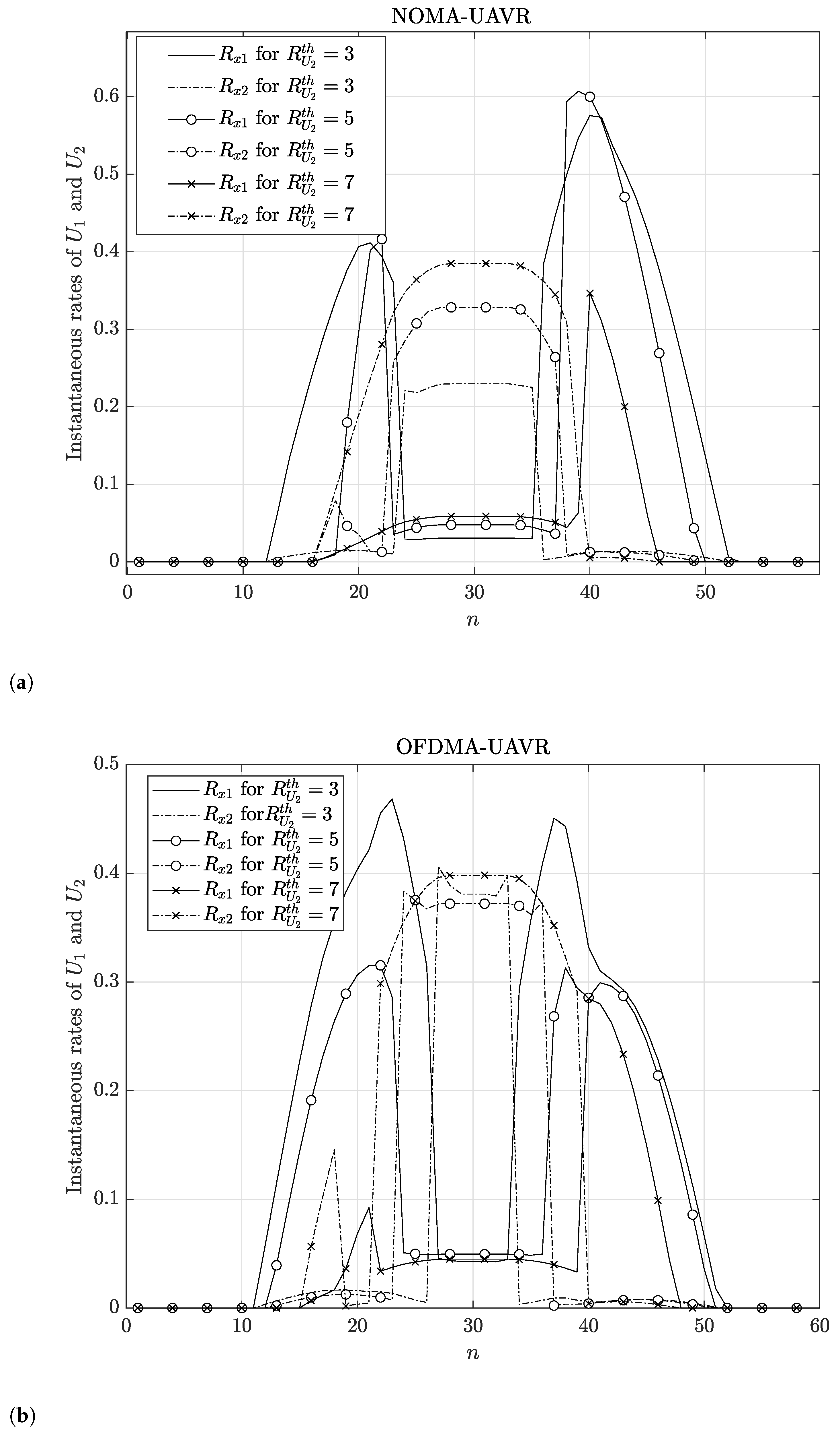
Figure 7 examines each user’s optimal patterns in the instantaneous rate. The instantaneous rate is positive during the ECP and equal to zero during the rest phases. The instantaneous rate of receives high values at the beginning and end of the ECP, while the instantaneous rate of receives elevated values in the middle of the ECP. These patterns can be elucidated by referring to the outcomes regarding the flight trajectory of R, transmission power levels, and (or ). When increases, the instantaneous rate of for each time slot becomes higher; moreover, the high-rate region of expands on both sides of the n axis, while the high-rate region of follows the inverse trend.
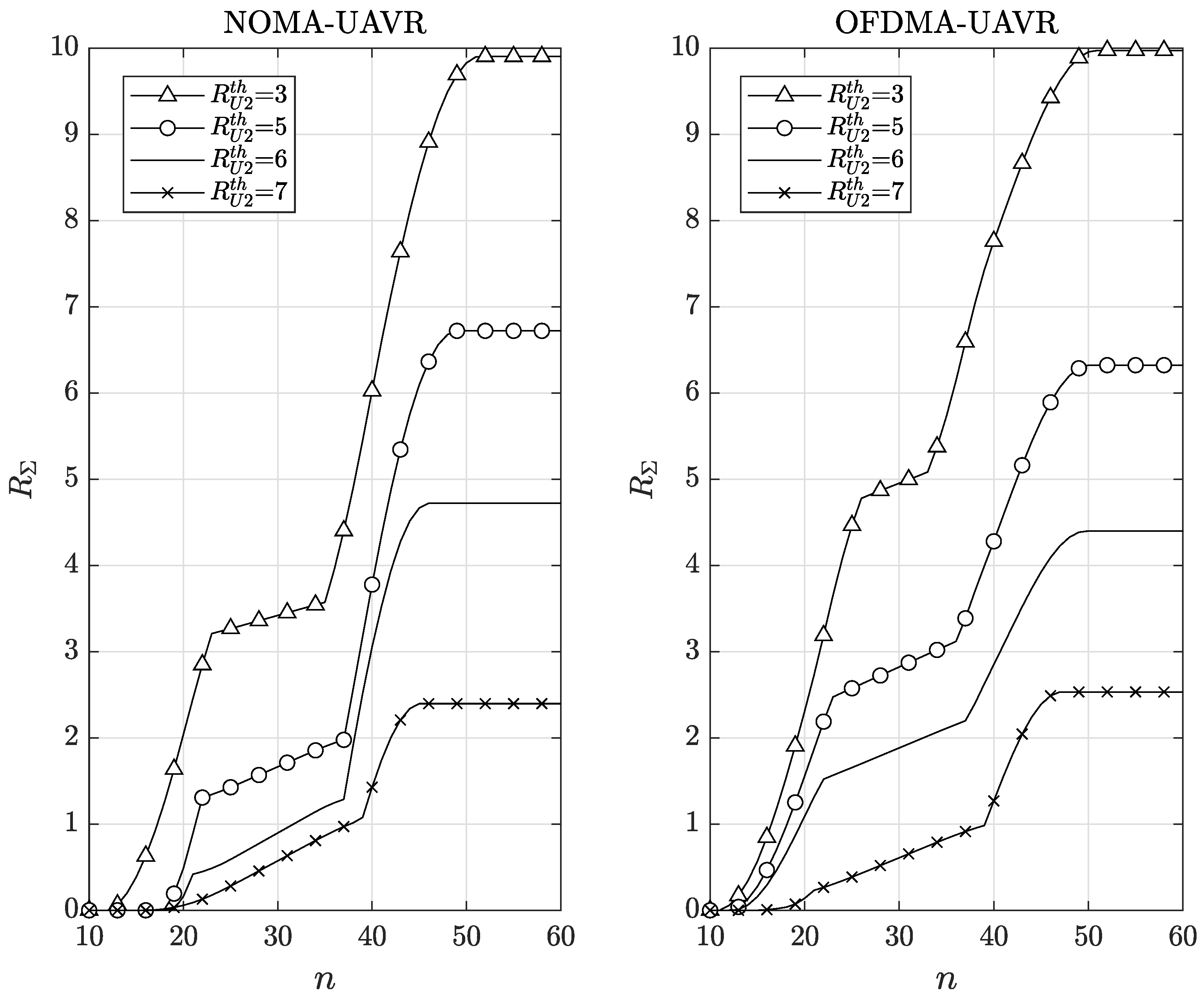
Figure 8 presents the trend in the optimal sum data rate for of and the optimal sum data rate for of . The purpose of our proposed algorithms is to maximize the system total data rate; however, Figure 8 shows that the obtained efficient solution using the proposed algorithm aims to maximize the sum data rate of while guaranteeing the required sum data rate of . This is a reasonable result due to the disadvantageous position of . Comparing OFDMA–UAVR and NOMA–UAVR protocols, we realize that the OFDMA–UAVR protocol outperforms the NOMA–UAVR protocol at very low or very high values for , whereas the NOMA–UAVR protocol outperforms the OFDMA–UAVR protocol at medium values for (such as or ). These results emphasize the benefits of the NOMA–UAVR protocol in providing fair communication service for the multi-user system.
7. Conclusions
In this paper, we proposed algorithms to solve the system sum data rate maximization problem of a UAV-based relaying two-user system for two multiple access techniques, OFDMA and NOMA. Our proposed algorithms aim to guarantee service for the far user while maximizing the sum data rate for both users. By applying the SCO and BCGD techniques, the proposed algorithms optimized the UAV’s flight trajectory, factors of resource allocation, and transmit powers. The numerical results confirmed that the system sum data rate significantly improved coverage. Furthermore, the optimal patterns in critical parameters, such as transmitted powers from GBS, the flight path and velocity of the UAV, and the resource allocation ratio, were revealed. Notably, the UAV tends to fly near or stay in specific areas, allowing efficient communication between the source and each user. The proposed algorithms tend to guarantee the minimum required sum data rate at the further destination user and maximize the sum data rate at the closer destination user. Finally, the obtained results demonstrate that the NOMA–UAVR protocol outperforms the OFDMA–UAVR protocol for the fair user-service scenario, whereas the OFDMA–UAVR protocol outperforms the NOMA–UAVR protocol in maximizing the system sum rate for very low or very high required sum rate for the far user. In this study, the optimal results were computed using solvers from the CVX optimization toolbox in Matlab for performance verification. However, in practical applications, CVX is not suitable due to its slow processing speed. To facilitate implementation on embedded hardware, real-time optimization solvers such as Structure-Aware Linear Solver [30] and CVXGEN [31] can be employed.
Author Contributions
Building model, analysis, and writing—original draft preparation: T.K.-X.; Building algorithms, performing experiments, validation, and supervision: A.L.-T. All authors have read and agreed to the published version of the manuscript.
Funding
This study is supported by the Research Fund of Hanoi University of Industry. Thanks to Tuan Van-Phu, who supported us during the process.
Conflicts of Interest
We wish to confirm that there are no known conflicts of interest associated with this paper. We confirm that the manuscript has been read and approved by all named authors and that there are no other persons who satisfied the criteria for authorship but are not listed. We further confirm that the order of authors listed in the manuscript has been approved by all of us.
Abbreviations
The following abbreviations are used in this manuscript:
| BCGD | Block-coordinate gradient descent |
| DU | Destination user |
| GBS | Round base station |
| OMA | Orthogonal multiple access |
| OFDMA | Orthogonal frequency division multiple access |
| ORA | Optimizing the resource allocation |
| NOMA | Non-orthogonal multiple access |
| SCO | Successive convex optimization |
| SIC | Successive interference cancellation |
| SINR | Signal-to-interference and noise ratio |
| TPO | Transmit power optimization |
| UAV | Unmanned aerial vehicles |
| UAVR | UAV relaying |
| UAVWC | UAV-assisted wireless communication |
References
- Vinogradov, E.; Sallouha, H.; De Bast, S.; Azari, M.M.; Pollin, S. Tutorial on UAV: A blue sky view on wireless communication. arXiv 2019, preprint. arXiv:1901.02306. [Google Scholar]
- Shen, T.; Ochiai, H. A UAV-Enabled Wireless Powered Sensor Network Based on NOMA and Cooperative Relaying with Altitude Optimization. IEEE Open J. Commun. Soc. 2021, 2, 21–34. [Google Scholar] [CrossRef]
- Michailidis, E.T.; Maliatsos, K.; Skoutas, D.N.; Vouyioukas, D.; Skianis, C. Secure UAV-aided mobile edge computing for IoT: A review. IEEE Access 2022, 10, 86353–86383. [Google Scholar] [CrossRef]
- Duong, T.Q.; Kim, K.J.; Kaleem, Z.; Bui, M.P.; Vo, N.S. UAV caching in 6G networks: A Survey on models, techniques, and applications. Phys. Commun. 2022, 51, 101532. [Google Scholar] [CrossRef]
- Liu, D.; Xu, Y.; Wang, J.; Chen, J.; Yao, K.; Wu, Q.; Anpalagan, A. Opportunistic UAV utilization in wireless networks: Motivations, applications, and challenges. IEEE Commun. Mag. 2020, 58, 62–68. [Google Scholar] [CrossRef]
- Guo, Y.; Yang, P. The Effectiveness of Unmanned Aerial Vehicle (UAV) on Farmlands with Artificial Intelligence (AI) System. In Proceedings of the 2022 7th International Conference on Financial Innovation and Economic Development (ICFIED 2022), Harbin, China, 21–23 January 2022; Atlantis Press: Dordrecht, The Netherlands, 2022; pp. 1664–1669. [Google Scholar]
- Thi Tam, D.; Cao Nguyen, B.; Manh Hoang, T.; The Dung, L.; Vinh, N.V.; Kim, T.; Lee, W. Combining FD-UAV and NOMA technologies in IoT sensor network with millimeter-wave communications. Int. J. Commun. Syst. 2023, e5492. [Google Scholar] [CrossRef]
- Greenberg, E.; Bar, A.; Klodzh, E. Los classification of UAV-to-ground links in built-up areas. In Proceedings of the 2019 IEEE International Conference on Microwaves, Antennas, Communications and Electronic Systems (COMCAS), Tel-Aviv, Israel, 4–6 November 2019; IEEE: Piscataway, NJ, USA, 2019; pp. 1–5. [Google Scholar]
- Cui, Z.; Briso-Rodríguez, C.; Guan, K.; Güvenç, I.; Zhong, Z. Wideband air-to-ground channel characterization for multiple propagation environments. IEEE Antennas Wirel. Propag. Lett. 2020, 19, 1634–1638. [Google Scholar] [CrossRef]
- Zhang, X.; Duan, L. Fast deployment of UAV networks for optimal wireless coverage. IEEE Trans. Mob. Comput. 2018, 18, 588–601. [Google Scholar] [CrossRef]
- Shahzadi, R.; Ali, M.; Khan, H.Z.; Naeem, M. UAV assisted 5G and beyond wireless networks: A survey. J. Netw. Comput. Appl. 2021, 189, 103114. [Google Scholar] [CrossRef]
- Sun, Y.; Wang, T.; Wang, S. Location optimization and user association for unmanned aerial vehicles assisted mobile networks. IEEE Trans. Veh. Technol. 2019, 68, 10056–10065. [Google Scholar] [CrossRef]
- Khan, S.K.; Naseem, U.; Sattar, A.; Waheed, N.; Mir, A.; Qazi, A.; Ismail, M. UAV-aided 5G network in suburban, urban, dense urban, and high-rise urban environments. In Proceedings of the 2020 IEEE 19th International Symposium on Network Computing and Applications (NCA), Cambridge, MA, USA, 24–27 November 2020; IEEE: Piscataway, NJ, USA, 2020; pp. 1–4. [Google Scholar]
- Liu, Y.; Yi, W.; Ding, Z.; Liu, X.; Dobre, O.; Al-Dhahir, N. Application of NOMA in 6G networks: Future vision and research opportunities for next generation multiple access. arXiv 2021, preprint. arXiv:2103.02334. [Google Scholar]
- Khan, W.U.; Jameel, F.; Jamshed, M.A.; Pervaiz, H.; Khan, S.; Liu, J. Efficient power allocation for NOMA-enabled IoT networks in 6G era. Phys. Commun. 2020, 39, 101043. [Google Scholar] [CrossRef]
- Liu, Y.; Yi, W.; Ding, Z.; Liu, X.; Dobre, O.A.; Al-Dhahir, N. Developing NOMA to Next Generation Multiple Access: Future Vision and Research Opportunities. IEEE Wirel. Commun. 2022, 29, 120–127. [Google Scholar] [CrossRef]
- Le, T.A.; Kong, H.Y. Evaluating the performance of cooperative NOMA with energy harvesting under physical layer security. Wirel. Pers. Commun. 2019, 108, 1037–1054. [Google Scholar] [CrossRef]
- Makki, B.; Chitti, K.; Behravan, A.; Alouini, M.S. A survey of NOMA: Current status and open research challenges. IEEE Open J. Commun. Soc. 2020, 1, 179–189. [Google Scholar] [CrossRef]
- Xiong, C.; Li, G.Y.; Zhang, S.; Chen, Y.; Xu, S. Energy-efficient resource allocation in OFDMA networks. IEEE Trans. Commun. 2012, 60, 3767–3778. [Google Scholar] [CrossRef]
- New, W.K.; Leow, C.Y.; Navaie, K.; Sun, Y.; Ding, Z. Application of NOMA for cellular-connected UAVs: Opportunities and challenges. Sci. China Inf. Sci. 2021, 64, 1–14. [Google Scholar] [CrossRef]
- Do, D.T.; Nguyen, T.T.T.; Nguyen, T.N.; Li, X.; Voznak, M. Uplink and downlink NOMA transmission using full-duplex UAV. IEEE Access 2020, 8, 164347–164364. [Google Scholar] [CrossRef]
- Zeng, Q.; Zhang, Z. The full-duplex device-to-device security communication under the coverage of unmanned aerial vehicle. KSII Trans. Internet Inf. Syst. (TIIS) 2019, 13, 1941–1960. [Google Scholar]
- Kumar, V.; Ding, Z.; Flanagan, M.F. On the Effective Rate of NOMA in Underlay Spectrum Sharing. IEEE Trans. Veh. Technol. 2021, 70, 12220–12225. [Google Scholar] [CrossRef]
- Van Phu, T.; Kong, H.Y. Secrecy sum rate maximization for UAV-aided NOMA communication systems. Ann. Telecommun. 2022, 77, 127–138. [Google Scholar] [CrossRef]
- Wang, N.; Li, F.; Chen, D.; Liu, L.; Bao, Z. NOMA-based Energy-Efficiency optimization for UAV enabled space-air-ground integrated relay networks. IEEE Trans. Veh. Technol. 2022, 71, 4129–4141. [Google Scholar] [CrossRef]
- Yang, Z.; Chen, M.; Liu, X.; Liu, Y.; Chen, Y.; Cui, S.; Poor, H.V. AI-driven UAV-NOMA-MEC in next generation wireless networks. IEEE Wirel. Commun. 2021, 28, 66–73. [Google Scholar] [CrossRef]
- Hariz, H.M.; Sheikhzadeh, S.; Mokari, N.; Javan, M.R.; Abbasi-Arand, B.; Jorswieck, E.A. Ai-based radio resource management and trajectory design for pd-noma communication in irs-uav assisted networks. arXiv 2021, preprint. arXiv:2111.03869. [Google Scholar]
- Senadhira, N.; Durrani, S.; Zhou, X.; Yang, N.; Ding, M. Uplink NOMA for Cellular-Connected UAV: Impact of UAV Trajectories and Altitude. IEEE Trans. Commun. 2020, 68, 5242–5258. [Google Scholar] [CrossRef]
- Li, Y.; Zhang, H.; Long, K.; Jiang, C.; Guizani, M. Joint Resource Allocation and Trajectory Optimization with QoS in UAV-Based NOMA Wireless Networks. IEEE Trans. Wirel. Commun. 2021, 20, 6343–6355. [Google Scholar] [CrossRef]
- Yamazaki, I.; Nooshabadi, S.; Tomov, S.; Dongarra, J. Structure-aware linear solver for realtime convex optimization for embedded systems. IEEE Embed. Syst. Lett. 2017, 9, 61–64. [Google Scholar] [CrossRef]
- Alshammari, F.; El-Refaie, A. Time-Varying Optimization-Based Consensus Control for Microgrid’s Secondary Control. In Proceedings of the 2021 IEEE Power & Energy Society Innovative Smart Grid Technologies Conference (ISGT), Washington, DC, USA, 16–18 February 2021; IEEE: Piscataway, NJ, USA, 2021; pp. 1–5. [Google Scholar]
Figure 1.
The proposed system model.

Figure 2.
(a) The bandwidth allocation in the OFDMA–UAVR scheme and (b) the power allocation in NOMA–UAVR scheme at S and R during the communication in each time slot.
Figure 2.
(a) The bandwidth allocation in the OFDMA–UAVR scheme and (b) the power allocation in NOMA–UAVR scheme at S and R during the communication in each time slot.

Figure 3.
The optimal flight path for the UAV under varying values.

Figure 4.
The optimal velocity of the UAV under varying values.

Figure 5.
The transmit powers of the (a) OFDMA–UAVR and (b) NOMA–UAVR protocols with different values of .
Figure 5.
The transmit powers of the (a) OFDMA–UAVR and (b) NOMA–UAVR protocols with different values of .


Figure 6.
The allocation parameter for resources under varying values.

Figure 7.
The instantaneous rate at each user for (a) NOMA–UAVR and (b) OFDMA–UAVR protocols with different values of .
Figure 7.
The instantaneous rate at each user for (a) NOMA–UAVR and (b) OFDMA–UAVR protocols with different values of .

Figure 8.
The optimal sum rate at each user under varying values.


Table 1.
Summary of related works.
| Previous Works | System Models | Operation Type | Primary Findings |
|---|---|---|---|
| [20] | UAV—downlink NOMA, multiple terrestrial BSs, terrestrial users, aerial users | Ground-to-air connections: modeling, analyzing, and simulating via two metrics as coverage probability and average user rate | Balanced performance between system throughput and fairness, and reduced delay |
| [21] | UAV—uplink and downlink NOMA | Full-duplex and half-duplex schemes over Nakagami-m channel: modeling, analyzing, and simulating via main metric as outage probability (OP) | Exploiting the benefits of UAV as a relay, save bandwidth, improving the data transmission efficiency, deriving closed-form expressions for OP |
| [25] | UAV with phased-array antennas and NOMA scheme | Modeling, analyzing, optimizing, and simulating via main metrics such as energy efficiency (EE), trajectory, NOMA scheduling, and NOMA power allocation | Their proposed system achieves high EE, and NOMA was shown to outperform OMA in UAV EE. |
| [26] | UAV—NOMA with AI | Proposing some AI techniques that can apply for UAV communication, using NOMA to serve terrestrial mobile users: analysis and presentation | Main techniques such as federated learning and reinforcement learning (RL) to address the intelligent task offloading and computing resource allocation |
| [27] | UAV with the uplink PD-NOMA and IRS | Multi IRS–UAV with ground BS and NOMA users: modeling, analyzing, optimizing, and simulating | Two different RL-based algorithms (DDQN and PPO) to minimize the average age of information of user |
| [28] | UAV and power-domain aerial–terrestrial NOMA (uplink scheme) | Concurrent uplink transmission of the aerial user (AU) and terrestrial user (TU) in uplink to UAV: modeling, analytical framework, simulating via the probability of achievable data rate | Determining the minimum height that AU needs to fly, enhancing the quality of services and showing the importance of modeling AU trajectory in UAV system |
| [29] | UAV—downlink NOMA | Optimizing joint resource allocation and UAV trajectory to maximize the total EE: using heuristic algorithm and logarithmic approximation | Improving the total energy efficiency and transmit power allocation, data rate, and computational complexity |
Table 2.
Summary of system variables.
| No. | Symbol | Description |
|---|---|---|
| 1 | P | Transmit power |
| 2 | B | Bandwidth |
| 3 | H | Fixed altitude |
| 4 | Initial location | |
| 5 | Final location | |
| 6 | T | Length of time |
| 7 | N | Time slots |
| 8 | Channel gain | |
| 9 | Bandwidth allocation factor in OFDM | |
| 10 | R | Instantaneous rate |
| 11 | Required sum rate | |
| 12 | Additive white Gaussian noise | |
| 13 | Power allocation factor of NOMA | |
| 14 | Power budget | |
| 15 | Maximum transmit power |
Disclaimer/Publisher’s Note: The statements, opinions and data contained in all publications are solely those of the individual author(s) and contributor(s) and not of MDPI and/or the editor(s). MDPI and/or the editor(s) disclaim responsibility for any injury to people or property resulting from any ideas, methods, instructions or products referred to in the content. |
© 2024 by the authors. Licensee MDPI, Basel, Switzerland. This article is an open access article distributed under the terms and conditions of the Creative Commons Attribution (CC BY) license (https://creativecommons.org/licenses/by/4.0/).
Share and Cite
MDPI and ACS Style
Kieu-Xuan, T.; Le-Thi, A. UAV-Assisted Cooperative NOMA and OFDM Communication Systems: Analysis and Optimization. J. Sens. Actuator Netw. 2024, 13, 18. https://doi.org/10.3390/jsan13010018
AMA Style
Kieu-Xuan T, Le-Thi A. UAV-Assisted Cooperative NOMA and OFDM Communication Systems: Analysis and Optimization. Journal of Sensor and Actuator Networks. 2024; 13(1):18. https://doi.org/10.3390/jsan13010018
Chicago/Turabian StyleKieu-Xuan, Thuc, and Anh Le-Thi. 2024. "UAV-Assisted Cooperative NOMA and OFDM Communication Systems: Analysis and Optimization" Journal of Sensor and Actuator Networks 13, no. 1: 18. https://doi.org/10.3390/jsan13010018
Note that from the first issue of 2016, this journal uses article numbers instead of page numbers. See further details here.