1. Introduction
The 2022 Global Report on Food Crises (GRFC 2022) has shed light on the alarming global food crisis, impacting approximately 193 million individuals in 53 countries, leading to severe food insecurity [
1]. This crisis has emerged due to a combination of factors, including geopolitical conflicts, the COVID-19 pandemic, rising food and fuel prices, and rapid population growth. As a result, the agricultural sector is compelled to embrace innovative approaches to meet the escalating demand for food production. Among these approaches, smart farming has garnered significant attention for its potential to revolutionize traditional agricultural practices into highly efficient and technologically advanced systems [
2].
Smart farming integrates advanced technologies including big data analytics, cloud computing infrastructure, image processing techniques, machine learning algorithms, and wireless sensor networks [
3]. These technologies enable real-time data acquisition, streamline labor-intensive operations, and optimize agricultural production in terms of quality and quantity [
4]. The Internet of Things (IoT) plays a crucial role in driving the advancement of smart farming, and finding practical utility in various domains including agriculture, smart cities, and healthcare [
5,
6,
7]. However, the deployment of smart farming in the rural areas of Thailand poses significant challenges due to limited network infrastructure. Rural agricultural regions are often located far from urban centers, making traditional network infrastructure investment economically infeasible. While cellular networks can provide signal distribution through Wi-Fi routers, their coverage range is limited to approximately 100 m, rendering them inadequate for large agricultural areas [
8].
LPWAN technology has emerged as a critical enabler for empowering smart farming applications by facilitating seamless connectivity between IoT devices and cloud computing systems, enabling efficient data processing [
9,
10]. LPWAN technology exhibits the ability to transmit signals to both urban and rural areas, covering distances of 5 km in urban environments and 15 km in rural regions [
11]. LPWAN technologies, designed to meet the growing demand for IoT devices, have garnered significant attention from academia and industry, offering broad area connectivity, optimized data rates, power consumption, and throughput on licensed and unlicensed frequency bands [
7,
12,
13].
A comprehensive comparative analysis [
13,
14] examined different LPWAN technologies, highlighting the exceptional capabilities of LoRa technology for large-scale IoT deployments. Moreover, the authors of [
15] conducted an extensive investigation, assessing the performance of wireless sensor network systems, emphasizing the remarkable efficiency achieved through the utilization of LoRa–Zigbee hybrid communication. The research provides substantial evidence supporting the superior outcomes derived from the synergistic implementation of these technologies. Consequently, LoRaWAN technology has emerged as the leading communication network within the LPWAN domain for IoT applications in smart agriculture, particularly in rural environments [
8,
16].
The precise placement of LoRaWAN gateways plays a pivotal role in influencing critical factors such as cost, gateway capacity, bitrate, and quality of service, thereby ensuring the efficient and reliable operation of the network. Extensive research has emphasized the substantial benefits derived from optimizing gateway placement, including a potential 40% reduction in the required number of gateways and a 70% decrease in collision probability [
17]. In vast agricultural regions, the utilization of clustering algorithms such as k-means and fuzzy c-means enhances uplink delivery rates and diminishes energy consumption [
18]. Furthermore, the particle swarm optimization (PSO) approach effectively identifies optimal gateway locations, yielding superior outcomes with an increasing number of gateways [
19]. The placement of gateways significantly influences the energy consumption of end devices, a critical factor for preserving battery life and autonomy [
20]. The meticulous identification of optimal gateway locations is crucial for ensuring comprehensive coverage [
21,
22]. In the study “LoRa-Based IoT Network Assessment in Rural and Urban Scenarios” [
23], the authors evaluated the performance of LoRa networks in diverse environments, emphasizing the importance of optimizing parameters for successful smart network deployment. Additionally, a study on gateway positioning strategies in a LoRaWAN [
24], compared various algorithms and grid-based methods, recommending fuzzy c-means and Gustafson–Kessel algorithms for enhanced performance and cost-effectiveness in gateway placement.
In this comprehensive examination, we delineate the gateway location selection problem within the framework of a LoRaWAN, encompassing considerations of cost, gateway capacity, and bitrate.
Figure 1 depicts the relationship between the gateway and the village, addressing crucial factors such as the foundational costs of establishing a gateway station, station setup expenditures, and gateway capacity. The village comprises end nodes poised to receive signals from the gateway, with the distance between these nodes facilitating signal reception. A strategic emphasis on cost considerations results in the meticulous allocation of a limited number of gateways, leading to reduced costs and a corresponding decrease in average bitrate. Conversely, prioritizing bitrate optimization entails the allocation of a more extensive gateway coverage to achieve equitable signal distribution, consequently incurring higher costs. The intricate interplay between system cost and bitrate maximization constitutes the central focus of our research exploration.
To evaluate the proposed algorithm’s effectiveness, a real case study conducted in the Ubon Ratchathani province of Thailand is presented. This study focuses on the multiple gateway location selection problem in LoRaWANs and utilizes data on village information, including location, distance, and the number of farms or agricultural households requiring LoRa signal coverage, as well as information on LoRaWAN gateway properties such as base cost, variable cost, capacity, range, and bitrate. The primary objectives of this research are twofold (1) to optimize the total system costs, with an emphasis on cost minimization, and (2) to maximize the bitrate for achieving comprehensive signal coverage across the network. To fulfill the desired goals, a multi-objective gateway location selection model is created, and the effectiveness of the objective function is assessed using Pareto front analysis and the weighted sum approach in conjunction with the TOPSIS method. The key contributions of this study are as follows:
Development of multiple gateway location selection models to optimize total system costs and maximize bitrate for efficient signal coverage;
Introduction of the novel M-VaNSAS algorithm, specifically tailored for solving the multiple gateway location selection problem in LoRaWANs;
Comparative analysis of the M-VaNSAS algorithm against other popular optimization algorithms such as the genetic algorithm (GA), differential evolution algorithm (DE), and particle swarm optimization algorithm (PSO).
The paper is organized as follows.
Section 2, Related Works, offers a thorough review of studies concerning gateway location selection in long-range wide area networks.
Section 3 provides a comprehensive overview of LoRa and LoRaWAN. In
Section 4, we present the methodology, which includes data collection, the development of the mathematical model problem formulation, and our proposed method.
Section 5 presents the computational results and framework. Finally,
Section 6 presents a comprehensive summary and offers valuable perspectives on prospective areas for further investigation.
2. Related Works
LoRaWANs are integral components of IoT infrastructures, connecting devices over extensive geographical areas. Effective gateway placement is paramount for achieving comprehensive coverage, efficient communication, and ensuring the overall success of IoT applications. This paper reviews the existing literature, emphasizing the multi-objective optimization of gateway location selection in LoRaWANs, specifically addressing the trade-off between system costs and bitrate maximization.
The gateway placement problem in LoRaWANs is multifaceted, involving considerations such as coverage, spectral efficiency, network redundancy, and system costs. Research by [
21] underscored the importance of achieving complete coverage while respecting constraints such as the number of nodes served per access point and required redundancy. Their k-dominating set concept introduced a greedy algorithm, demonstrating efficacy in both randomly generated and real smart metering network topologies. In a complementary approach, the authors of [
22] developed a mathematical model for optimizing coverage, utilizing the LINGO modeling program. The spatial distribution of clients, radio signal propagation, gateway capacity, topography, obstacles, and network redundancy were identified as pivotal factors influencing gateway placement decisions. This holistic model provides insights into the intricate interplay of these factors, offering a comprehensive approach to gateway location selection.
Dynamic IoT applications were addressed in [
25], where the DPLACE model integrates operational and capital expenses (OPEX and CAPEX) with quality of service (QoS) requirements. Leveraging k-means and fuzzy c-means algorithms, DPLACE optimizes gateway placement, emphasizing the dynamic nature of IoT deployments. Similarly, authors of [
26] focused on low-power wide-area sensor networks, proposing greedy algorithms for optimal gateway locations with a focus on interference cancellation and power considerations. To balance costs and efficiency in large-scale IoT applications, the authors of [
27] introduced an integer linear programming (ILP) approach. This research underscored the critical role of gateway placement decisions in minimizing network costs while meeting QoS requirements.
A study by [
28] explored the impact of gateway placement on network performance, introducing a discounted upper confidence bound (DUCB) multi-armed bandit (MAB) algorithm. The algorithm optimizes LoRa parameters, showcasing improvements in energy efficiency and overall performance. Scalability concerns were addressed in [
29], evaluating the potential of LoRa networks through dynamic communication parameter selection and the introduction of multiple sinks. Strategic implementation strategies were emphasized to overcome capacity limitations and ensure scalability. In the context of specific applications, the authors of [
30] evaluated the feasibility of LoRaWAN technology for coordinating interface protection systems in smart grids. Their study provides insights into the number of devices a single gateway can manage and corresponding response times, highlighting the adaptability of LoRaWAN technology. The authors of [
31] focused on optimizing gateway placement in low-height networks, such as smart irrigation systems. The proposed dynamic programming algorithm aimed to improve the efficiency and reliability of LoRa communication in real-world scenarios. Enhancements and optimizations for LoRaWANs were proposed in [
32], introducing the duty cycle gateway selection (DCGS) algorithm. DCGS distributes downlink traffic among available gateways based on their duty cycle time off, improving confirmed packet delivery rates and reducing retransmissions and collisions.
The ReLoRaWAN framework, presented in [
33], collaborates with multiple gateways to recover distorted packet payloads. The tri-operation integrated data recovery (TIDR) algorithm significantly improves packet delivery ratio and end device power consumption compared to existing works. In conclusion, this literature review underscores the complexity of gateway placement in LoRaWANs, emphasizing the need to consider factors such as coverage, cost, interference, and application-specific requirements. The methodologies proposed in the reviewed studies provide valuable insights into addressing the gateway placement problem, contributing to the overall efficiency and reliability of LoRaWANs. Tradeoff analysis between system costs and bitrate maximization is a critical aspect of this optimization process, requiring careful consideration of various factors to ensure the seamless integration of IoT applications over extensive geographical areas. The diverse studies presented collectively contribute to a comprehensive understanding of gateway placement in LoRaWANs, offering insights into optimizing coverage, minimizing costs, and enhancing overall network performance. A summarized overview of the related work is shown in
Table 1.
Table 1 presents a comparison in which the current study explores a multi-objective optimization problem, emphasizing a trade-off analysis between system costs and the maximization of bitrate in the selection of LoRaWAN gateway locations. This research adds to existing knowledge by offering insights into the complexities of optimizing coverage, reducing costs, and maximizing bitrate within the framework of large-scale IoT deployments. This study’s distinctive perspective and methodology contribute to the continuous conversation on effective gateway placement, thereby improving the reliability and efficiency of LoRaWANs.
3. LoRa and LoRaWAN Overview
LoRa (long-range) technology has emerged as an innovative solution that revolutionizes smart cities across multiple domains such as smart environment, smart mobility, smart energy, and smart living. Developed specifically for low-power wide area networks (LPWANs), LoRa utilizes chirp spread spectrum (CSS), a highly effective spread spectrum modulation technique. This enables LoRa to provide reliable, long-range wireless communication, with impressive coverage of up to 5 km in urban environments and 15 km in rural regions [
11]. In Thailand, LoRa implementations adhere to the AS923 MHz standard for unlicensed bands, and the adoption of the 920–925 MHz frequency band has been observed [
34]. The fundamental parameters in LoRa modulation consist of the spreading factor (SF), bandwidth (BW), and code rate (CR). LoRa modulation supports six spreading factors ranging from SF7 to SF12, each associated with a specific bit rate and estimated range, as detailed in
Table 2 [
11,
35].
Table 2 provides a comprehensive comparison of the six spreading factors (SF7 to SF12), presenting their respective bit-rates, time on air (ToA) for uplink messages on a 125 kHz bandwidth, coding rate (CR) 4/5, packet error rate (PER) of 1%, and estimated ranges in rural environments. The duration of airtime values corresponds to a payload size of 10 bytes for each spreading factor. Decreasing the spreading factors leads to increased bit rates, decreased time on air, and reduced transmission ranges. Conversely, increasing the spreading factors results in decreased bit rates, longer time on air, and extended transmission ranges. LoRaWANs (long-range wide area networks), established under the guidance of the LoRa Alliance, a renowned non-profit organization shaping global communication standards, leverage the benefits of LoRa technology. These advantages encompass reduced noise, mitigated interference, and amplified channel capacity. These networks facilitate the expansion of wide-area networks by seamlessly connecting end nodes to cloud computing platforms through LoRaWAN gateways. In LoRaWANs, gateways play a crucial role as intermediaries, efficiently enabling the exchange of information between end devices and a central core network server. It is noteworthy that LoRaWANs exhibit remarkable efficiency when it comes to transmitting small data packets, particularly those containing sensor readings [
36].
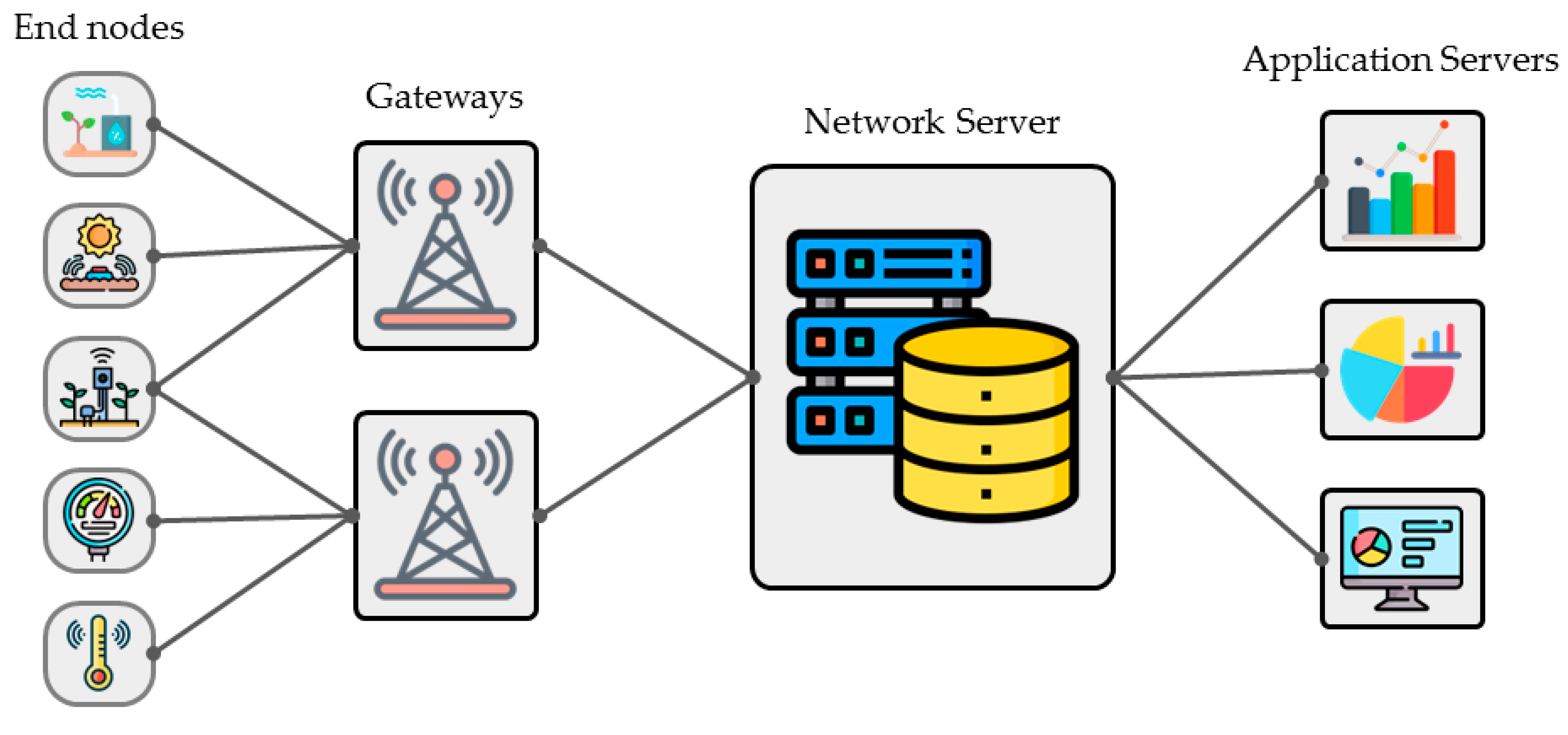
Figure 2 depicts the architectural framework of LoRaWANs.
Figure 2 presents an illustrative representation of the key components that constitute the foundational framework of the LoRaWAN system. These essential components encompass end nodes, gateways, network servers, and an application server. End nodes serve a vital role in the system, as they are responsible for transmitting sensor data and receiving commands from the network server, enabling access to information and control over devices. Within the LoRaWAN protocol, there are three distinct classes of end nodes Class A, B, and C. Gateways act as intermediaries in the system architecture, intercepting LoRa signals transmitted by end nodes and relaying the data to the server through internet protocol (IP). This enables seamless and uninterrupted communication between the end nodes and the network server. The network servers play a crucial role in the system’s operation by handling the processing of data received from gateways. They perform tasks such as data management, security enforcement, and routing optimization. Application servers or applications utilize the data obtained from the network server to enable various functionalities and services. They leverage the processed data to derive insights, trigger actions, and provide valuable applications for end-users.
4. Methodology
In our research methodology, we aim to achieve the optimal selection of gateway locations in LoRaWANs by analyzing the tradeoffs between system costs and bitrate maximization. Our approach considers the distinctive attributes and deployment limitations of the network, ensuring a comprehensive and customized methodology for gateway selection. This section encompasses three key components: data collection, mathematical model formulation, and the proposed method.
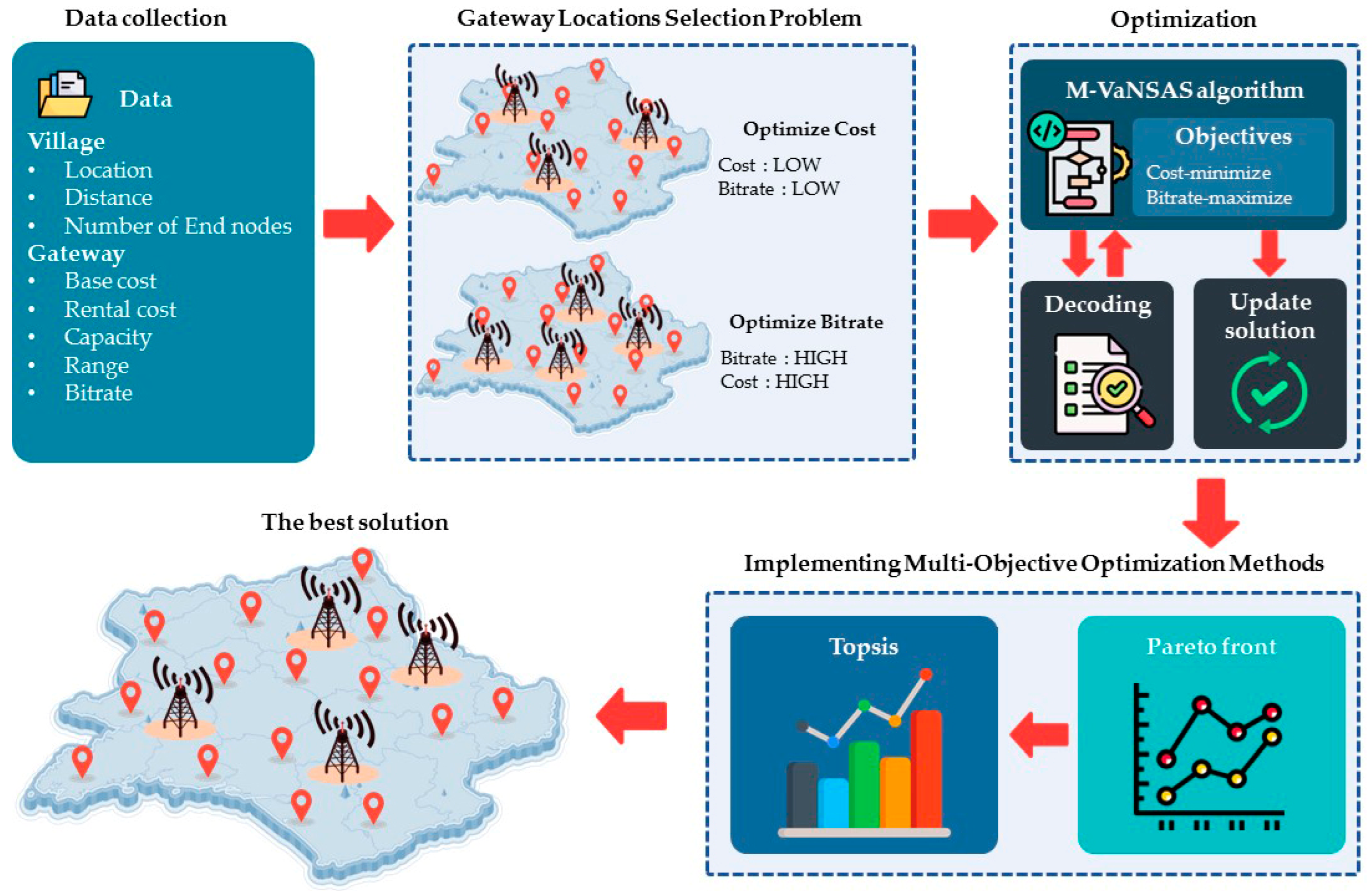
Figure 3 illustrates a comprehensive framework for the optimal selection of gateway locations in LoRaWANs. In the data collection phase, critical parameters such as the number of end nodes, villages, base cost, rental cost, capacity, and bitrate scores across different range categories were gathered from reputable agencies. The gateway location selection problem section introduces a mathematical model addressing the optimal selection of gateway locations, offering a detailed problem statement and a systematic approach. The optimization section introduces the M-VaNSAS algorithm, employing a four-step process for effective solution identification. Implementing multi-objective optimization methods focuses on the Pareto front and TOPSIS, utilizing them to manage conflicting objectives. The best solution, derived from M-VaNSAS analysis, undergoes meticulous evaluation to optimize system costs and maximize bitrate, contributing to the overarching goal of achieving the most suitable gateway location selection in LoRaWANs while considering tradeoffs between system costs and bitrate maximization.
4.1. Data Collection
To achieve our objectives, we gathered secondary data from reputable agencies, concentrating on critical parameters such as the number of end nodes, villages, base cost, rental cost, capacity, and bitrate scores across different range categories. These data played a critical role in establishing our methodology. The data collection process involved compiling information based on the parameters and values presented in
Table 3 and
Table 4.
Table 3 outlines the key parameters and their corresponding values. The dataset comprises 295,942 end nodes distributed across 2199 villages within the Ubon Ratchathani province. The initial cost associated with the establishment of a LoRaWAN gateway station is fixed at THB 100,000 per gateway. This serves as the base investment required to set up a functional LoRaWAN gateway, while the rental cost varies from THB 5000 to 30,000, exhibiting random fluctuations within this range. Furthermore, the capacity parameter signifies the capability of a LoRaWAN gateway service to support 2500 end nodes per gateway.
Table 4 presents an assessment of the bitrate scores allocated to various distance categories between the LoRaWAN gateway and the corresponding villages (
—the bitrate performance score for the distance between location
r and village
v). This evaluation provides insights into the performance of data transmission rates across different ranges in the LoRaWAN infrastructure. These scores assume a critical role in assessing the communication quality between the gateway and the end nodes at varying distances. The scoring system assigns a bitrate score of 4 to range distances of 0–2 km, indicating the highest level of data transmission efficiency. As the range extends to 3–4 km, the score diminishes to 3, signifying a slight reduction in performance. For distances of 5–6 km, the bitrate score further decreases to 2, indicating a decline in transmission capacity. Finally, distances spanning 7–8 km receive the lowest bitrate score of 1, indicating the most limited data transmission capability.
4.2. Gateway Location Selection Problem
To achieve an optimal selection of gateway locations in LoRaWANs, it is crucial to account for both the system costs and the quality of service. This section provides a comprehensive problem statement and presents a mathematical model for the optimal selection of multiple gateway locations in LoRaWANs, considering the aforementioned factors.
Indices| r, l | The location of LoRaWAN gateways, where r, l = 1…R; |
| v | The villages under consideration, where v = 1…V. |
Parameters| R | The total number of permissible locations for deploying LoRaWAN gateways, R; |
| V | The overall count of villages, V; |
| The maximum signal range of coverage between a LoRaWAN gateway and a village; |
| The count of populations accessing a LoRaWAN gateway within village v; |
| The distance separating location r and village v; |
| The bitrate performance score for the distance between location r and village v; |
| The operational capacity of LoRaWAN gateway r; |
| The cost of leasing the space for the station location of LoRaWAN gateway r. |
Equation (1) represents the primary objective function, designed to optimize the overall cost incurred during the deployment of LoRaWAN gateways. In contrast, Equation (2) corresponds to the secondary objective function, targeting bitrate performance maximization. Equation (3) encompasses the constraints that guarantee each village is adequately served by at least one LoRaWAN gateway. Moreover, Equation (4) introduces constraints that restrict a LoRaWAN gateway positioned at location r to only serve village v if it is deployed at that specific location. To ensure adherence to the defined coverage range, Equation (5) imposes limitations on the distance between LoRaWAN gateway r and village v, ensuring it remains within the permissible maximum distance. Furthermore, Equation (6) enforces constraints on the total number of end nodes served by gateway r to align with its designated capacity. Lastly, Equation (7) defines constraints that stipulate the binary nature of decision variables and , which signify the selection of gateway locations. The mathematical model formulated in this study considers both cost optimization and bitrate maximization while adhering to constraints that ensure efficient and reliable LoRaWAN operation.
4.3. Optimization
In this research, we introduce a novel metaheuristic algorithm called the M-VaNSAS algorithm. This algorithm has been meticulously designed to effectively navigate diverse solution spaces and identify the most optimal solutions [
38]. The M-VaNSAS algorithm follows a structured four-step approach: (1) generating an initial population of trajectories known as tracks, (2) conducting an extensive exploration of routes using black box operators, (3) continuously updating heuristic information by adapting the tracks, and (4) iterative refinement through repeated execution of steps (2) and (3) until the specified termination conditions are satisfied [
39]. In the subsequent sections, we provide a comprehensive explanation of our implementation of the M-VaNSAS algorithm to tackle the problem under investigation.
4.3.1. Initial Population Generation
To commence, an initial population of tracks (PT) is created by randomly generating a specified number of tracks. As an illustration,
Table 5 presents an example with five tracks; each vector within the set possesses a dimension of 1 × D, where D denotes the total number of villages. In this study, D is set to 10. The initial tracks are generated by uniformly selecting real numbers between 0 and 1, utilizing Equation (8):
where
represents the value at position
j in track
i during the first iteration. The index
j represents the number of villages, while
i corresponds to the predefined number of tracks. Moreover, the algorithm generates two distinct sets of tracks, namely the optimal tracks (BT) set and the random tracks (RT) set. In the first iteration, the BT set is formed by collecting the best solution discovered in iterations 1 through
t, and the RT set is randomly chosen, using Equations (9) and (10), respectively.
In Equations (9) and (10),
represents the set of best solutions collected from iterations 1 through
t, while
is selected randomly according to the provided formula. The values of
are updated using Equation (11), where the value of
in iteration
t + 1 is equal to the value of
in iteration
t, utilizing a chosen IB operator. An exemplary demonstration of five tracks, randomly generated, can be observed in
Table 5.
Table 5 presents an illustrative example consisting of five randomly generated tracks. For instance, Track 1 consists of ten villages with corresponding values of 0.74, 0.20, 0.73, 0.84, 0.12, 0.32, 0.09, 0.29, 0.27, and 0.82. These values represent the contributions of the villages to the problem solution and are further decoded using the decoding method.
The decoding procedure employed in this study encompasses three sequential steps. Firstly, the villages are allocated to available LoRaWAN gateways while ensuring that each village is served by at least one gateway and that the maximum distance and total population constraints of each gateway are not violated. Secondly, the element values are sorted in ascending order. Lastly, the assigned LoRaWAN gateways are positioned at the initial slots, and the remaining villages are subsequently assigned to the remaining gateways. This iterative process continues until a viable solution is achieved during the assignment phase. The detailed steps of the decoding method are elaborated as follows:
Table 6 exhibits the sorting outcomes of the element values in Track 1. Initially, the values for Villages 1 to 10 are 0.74, 0.20, 0.73, 0.84, 0.12, 0.32, 0.09, 0.29, 0.27, and 0.82, respectively. These values are arranged in ascending order based on their magnitudes, resulting in the new sequence of villages: 7, 5, 2, 9, 8, 6, 3, 1, 10, and 4. The corresponding values are 0.09, 0.12, 0.20, 0.27, 0.29, 0.32, 0.73, 0.74, 0.82, and 0.84. This sorted sequence is subsequently employed in the subsequent steps of the proposed decoding method.
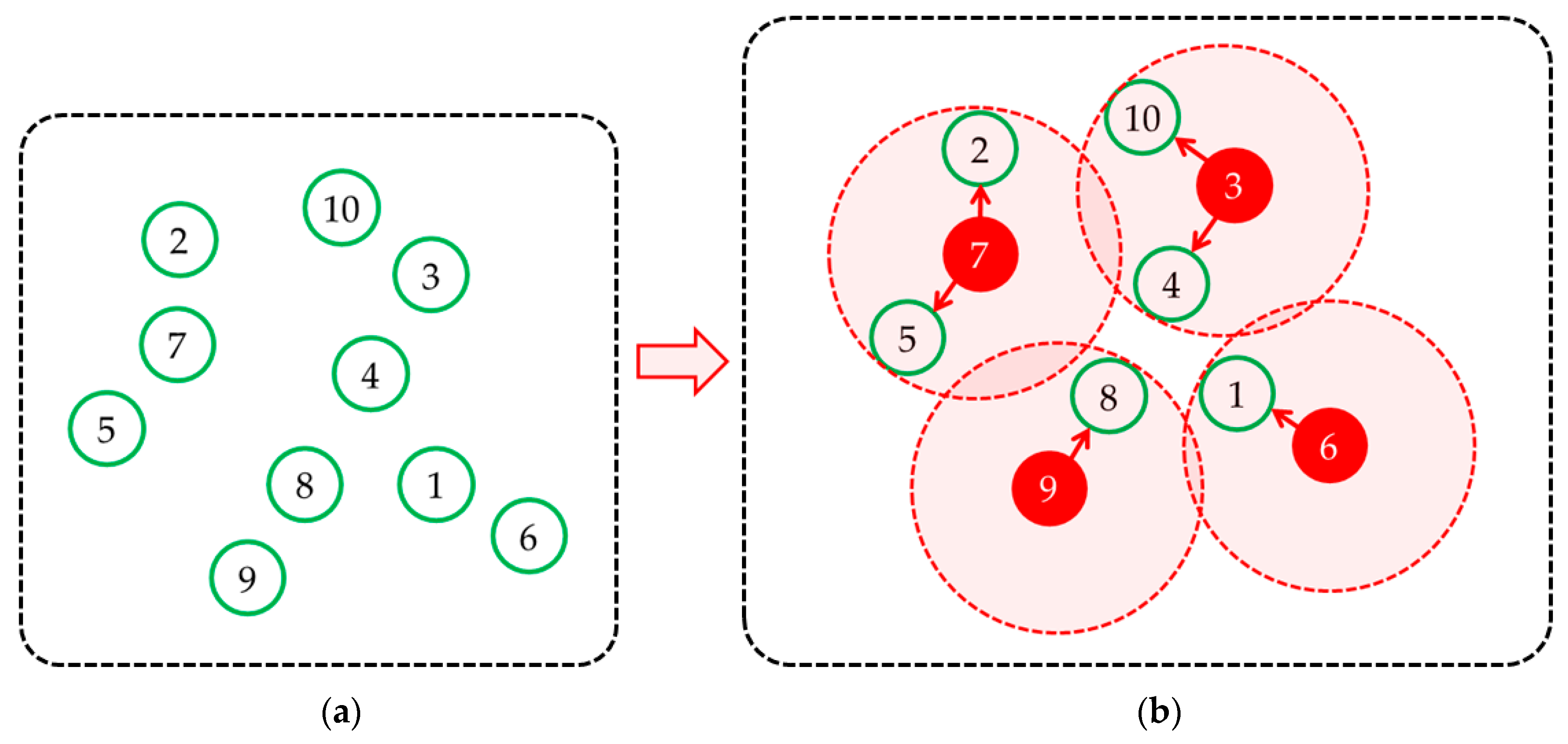
Figure 4 illustrates the decoding method, where
Figure 4a displays the arrangement of the new sequence of elements to determine the positions of LoRaWAN gateways, and
Figure 4b showcases the assignment of villages to these gateways. Commencing with Village 7 being assigned to the position of LoRaWAN gateway 1, Villages 7, 5, and 2 are allocated to this position as they meet the assignment criteria. Following that, Village 9, the second village in order, is assigned to the position of LoRaWAN gateway 2, along with Village 8, which also satisfies the assignment conditions. Similarly, Village 6, the third village in order, is assigned to the position of LoRaWAN gateway 3, along with Village 1. Lastly, Village 3 is assigned to the position of LoRaWAN gateway 4, together with Villages 10 and 4, as they fulfill the assignment conditions.
4.3.2. Updating Black Box Probability
Within our methodology, the tracks undergo continuous exploration within the Improvement box (IB), which encompasses advanced solution enhancement techniques that surpass simple local search. The IB consists of several methods, including DE-inspired move (DIM), random-transit (RT), best-transit (BT), and inter-transit (IT). The selection of the preferred method from the IB is determined using a roulette wheel selection approach, guided by Equation (11).
In Equation (11), denotes the likelihood of choosing method b from the improvement box (IB) in iteration t. denotes the total number of tracks that have previously chosen method b. denotes the mean objective value across all tracks that have opted for method b in the previous iterations. represents the objective value of the most optimal global solution identified before iteration t. denotes a reward value that increments by 1 when an intervention method from the bundle successfully identifies the solution with the highest level of optimality achieved in the previous iteration. In case the intervention method fails to identify such a solution, the reward value is set to 0. B denotes the total number of methods in the IB, while F and K represent scaling and parameter factors, respectively (F = 0.5, K = 1). Equation (11) guides the decision-making process for selecting the method from the IB in each iteration, considering four key factors that steer the solution towards promising search areas. These factors encompass the frequency at which tracks select the method, the average solution value of tracks that choose the method, the inclusion of current best solutions within the method, and the proximity of the average solution of tracks selecting the method to the solution of the best-performing method. It is important to note that if a method produces favorable solutions in previous iterations, its probability of being selected in the current iteration increases.
4.3.3. Improvement Box Operations
Within our methodology, we incorporate four improvement boxes, namely DE-inspired move, random transit, best transit, and inter-transit, as suggested by reputable sources [
39,
40,
41,
42]. These improvement boxes are executed using Equations (12)–(15).
In the above equations,
represents the newly generated value at position
j using the improvement boxes (IBs). During each iteration,
represents the value of element
j in track
i, where
r and
n denote different elements from the set of tracks (1 to
E) that are not equal to
i.
is a randomly generated number for position
j in track
i, and
is a randomly generated number for element
j in track
i during iteration
t, ranging from 0 to 1. The crossover rate (CR) is set at 0.8, following recommendations from reputable sources [
42]. While our M-VaNSAS work builds upon the work in [
39], we enhance it by incorporating an additional black box that employs DE mutation equations within the track improvement process, thereby introducing DE properties into the algorithm.
4.3.4. Track Update
During this step, we proceed to update specific heuristic information utilized in Equation (11), specifically addressing the variables outlined in Equation (16).
As described in Equation (16), represents the objective function value of , while represents the objective function value of . To determine the track for the next iteration, we choose the one with the lower value between and .
We continue the iterative process of executing
Section 4.3.2,
Section 4.3.3 and
Section 4.3.4 until the specified termination criterion is satisfied, ensuring that this rigorous methodology is adhered to. Our primary objective is to methodically explore the solution space and identify the most optimal solutions for the specified problem. The M-VaNSAS algorithm (Algorithm 1), with its precisely defined steps and operators, presents a systematic and efficient approach to effectively addressing the challenges involved in optimizing gateway location selections within LoRaWANs. The pseudocode representation of the M-VaNSAS algorithm is presented below for reference.
| Algorithm 1: M-VaNSAS |
| 1 | Section 4.3.1: Initial Population Generation |
| 2 | Initialize the population of tracks (PT) |
| 3 | Create an empty set for the initial tracks (IT) |
| 4 | Create an empty set for the best tracks (BT) |
| 5 | Create an empty set for the random tracks (RT) |
| 6 | |
| 7 | for i = 1 to NT do |
| 8 | Create a new track (T) of dimension 1 × D |
| 9 | for j = 1 to D do |
| 10 | Assign a random value to using Equation (8) |
| 11 | end for |
| 12 | Add T to the initial tracks (IT) |
| 13 | end for |
| 14 | |
| 15 | Generate random values for the best tracks (BT) using Equation (9) |
| 16 | Generate random values for the random tracks (RT) using Equation (10) |
| 17 | |
| 18 | Section 4.3.2: Updating Black Box Probability (IB) |
| 19 | for t = 1 to MaxIterations do |
| 20 | Calculate the probability for each black box using Equation (11) |
| 21 | end for |
| 22 | |
| 23 | Section 4.3.3: Improvement Box Operations |
| 24 | for t = 1 to MaxIterations do |
| 25 | for each track T in IT do |
| 26 | Select a black box operation (IB) based on the calculated probabilities |
| 27 | Perform the selected IB operation on T using Equations (12)–(15) |
| 28 | end for |
| 29 | end for |
| 30 | |
| 31 | Section 4.3.4: Track Update |
| 32 | for each track T in IT do |
| 33 | Update track T by comparing the objective function values of the current track and the modified track using |
| 34 | Equation (16) |
| 35 | end for |
| 36 | |
| 37 | Section 4.3.5: Repeat Section 4.3.2, Section 4.3.3 and Section 4.3.4 |
| 38 | Repeat Section 4.3.2, Section 4.3.3 and Section 4.3.4 until the specified termination criterion is satisfied |
The provided pseudocode presents a concise summary of the key procedures in the M-VaNSAS algorithm. It encompasses various steps, commencing with the generation of the initial population and continuing with iterative updates of the tracks until the predefined termination condition is met. Notably, it encompasses essential operations such as the initialization of initial tracks, the iterative adjustment of the probability associated with the black box, the execution of black box operations, and the subsequent updates of the tracks based on the values derived from the objective function. This pseudocode serves as a comprehensive guide to the implementation of the M-VaNSAS algorithm.
The gateway location selection problem falls within the category of NP-hard problems and is considered a generalized assignment problem. As the number of nodes increases, locating them within a limited time frame becomes impractical. To address this challenge, various metaheuristics, including genetic algorithms, ant colony optimization, simulated annealing, and M-VaNSAS, were devised to efficiently solve the problem within a constrained timeframe. M-VaNSAS, for instance, can yield feasible solutions with a time complexity of O(T*PT*D), where T represents iterations, PT denotes the population of tracks, and D signifies dimensions.
4.4. Implementing Multi-Objective Optimization Methods
The segment dedicated to the implementation of multi-objective optimization methods comprises two key components: the Pareto front and TOPSIS. The Pareto front, recognized as the set of Pareto-optimal solutions, serves as a robust methodology for effectively managing conflicting objectives in decision-making. To assess the effectiveness of solutions within the Pareto front, we employ the technique for order of preference by similarity to the ideal solution (TOPSIS) for our analysis. TOPSIS aids in creating a normalized decision matrix, effectively transforming various attribute dimensions into non-dimensional attributes.
4.4.1. Pareto Front
The Pareto front, known as the Pareto-optimal solution set, serves as a powerful methodology for addressing the challenge of conflicting objectives in decision-making. In this study, we apply the Pareto front approach to the complex task of selecting optimal locations for multi-gateway deployment in large-scale LoRaWANs. Our objective is to achieve a harmonious equilibrium between minimizing overall costs and maximizing bitrate, as shown in Equation (17).
To formalize the problem, we utilize a general equation denoted as Equation (17), where the objective function represents target i during the sub-calculation. Specifically, for our endeavor in multi-gateway deployment in LoRaWANs, we adopt Equation (18) as the objective function. The primary objective is to minimize total costs while concurrently maximizing the bitrate. Notably, the weights and correspond to the random allocation of significance to the first and second objectives, respectively, subject to the constraint that follows a uniform distribution U (0, 1).
The objective functions
and
align with objectives
and
, respectively, illustrating the inherent conflict between these objectives. Equation (18) encapsulates the overarching objective, seeking to maximize
Z. This equation skillfully balances the negative summation of costs (weighted by −
) against the positive summation of bitrate scores (weighted by
). By optimizing this equation, we can derive the Pareto-optimal values that strike a judicious compromise between cost reduction and achieving a high bitrate.
Within this context, the Pareto front assumes a crucial role in capturing the most favorable feasible solutions from a range of conflicting objectives. This approach enables the exploration of diverse deployment patterns in multi-gateway scenarios, taking into account cost optimization and the attainment of the highest possible bitrate. The objectives and represent the respective objective functions for targets 1 and 2 within the set R of viable options. Here, = (, , ..., ) represents the collection of decision vectors, and represents the collection of objective functions for vector y. It is important to note that the values of hold greater significance than , and the condition must hold for .
4.4.2. Analyze Pareto Front Using TOPSIS
To evaluate the efficacy of the solutions within the Pareto front, we employ the technique for order of preference by similarity to the ideal solution (TOPSIS) [
43] for our analysis. TOPSIS facilitates the development of a normalized decision matrix, which efficiently converts diverse attribute dimensions into non-dimensional attributes. This transformation, illustrated in Equations (19)–(25), establishes a standardized framework for comprehensive analysis and comparison of the solutions, ensuring a rigorous evaluation process.
The TOPSIS method constructs a normalized decision matrix using Equations (19) and (20) to transform the attribute dimensions into non-dimensional attributes. Here, represents the non-dimensional attribute value for point l and objective v, while denotes the normalized value of the objective function. The predefined weights determine the relative importance of each objective function. The positive ideal solution and the negative ideal solution is represented by and , respectively, which correspond to the sets of positive and negative objective functions. The separation measures and are employed to quantify the distances between each alternative and the ideal solutions. These measures enable the calculation of proximity in relation to the ideal solution, denoted as . The parameter set with the solution with a value closest to 1 is considered the most favorable option, indicating its high degree of alignment with the ideal objectives.
5. Computational Results and Framework
This section presents a detailed analysis of the computational results and framework for optimizing the selection of multiple gateway locations in LoRaWANs. The experiments were conducted using the DE, GA, PSO, and M-VaNSAS algorithms, with the objective of minimizing system costs and maximizing bitrate. The obtained solutions were compared to evaluate the performance of each algorithm and provide valuable insights into their effectiveness. The proposed method was created using Python 3 and executed on Google Colab resources. The computational setup comprised an Intel(R) Xeon(R) CPU @ 2.20 GHz, accompanied by 12.7 GB of RAM and 107.7 GB of disk space.
5.1. The Solutions
The results revealed interesting findings and significant differences among the solutions generated using each algorithm. Firstly, the GA algorithm produced a set of solutions that achieved a range of cost and bitrate values. However, the trade-off between cost and bitrate was not optimal, as some solutions exhibited higher costs for relatively lower bitrates. This indicates that the GA algorithm struggled to effectively balance the two objectives. On the other hand, the DE algorithm performed slightly better than the GA algorithm in terms of achieving a more balanced trade-off between cost and bitrate. The solutions obtained with DE showed improvements in both cost reduction and bitrate maximization compared to the GA solutions. However, there were still instances where the achieved bitrates were not optimal, indicating room for further enhancement. The PSO algorithm exhibited promising results, with solutions that demonstrated a more favorable trade-off between cost and bitrate compared to both GA and DE. The solutions obtained from PSO achieved lower costs while maintaining higher bitrates, indicating a more efficient allocation of gateway locations. This suggests that the PSO algorithm was able to effectively explore the solution space and identify better solutions for analyzing the tradeoffs between system costs and bitrate maximization for the optimal selection of gateway locations in LoRaWANs.
Lastly, the M-VaNSAS algorithm, specifically designed for this problem, outperformed all other algorithms in terms of generating superior solutions. The solutions obtained from M-VaNSAS consistently achieved the best trade-off between system costs and bitrate maximization. This demonstrates the effectiveness of the proposed algorithm in generating optimized solutions for analyzing the tradeoffs between system costs and bitrate maximization for the optimal selection of gateway locations in LoRaWANs.
As seen in
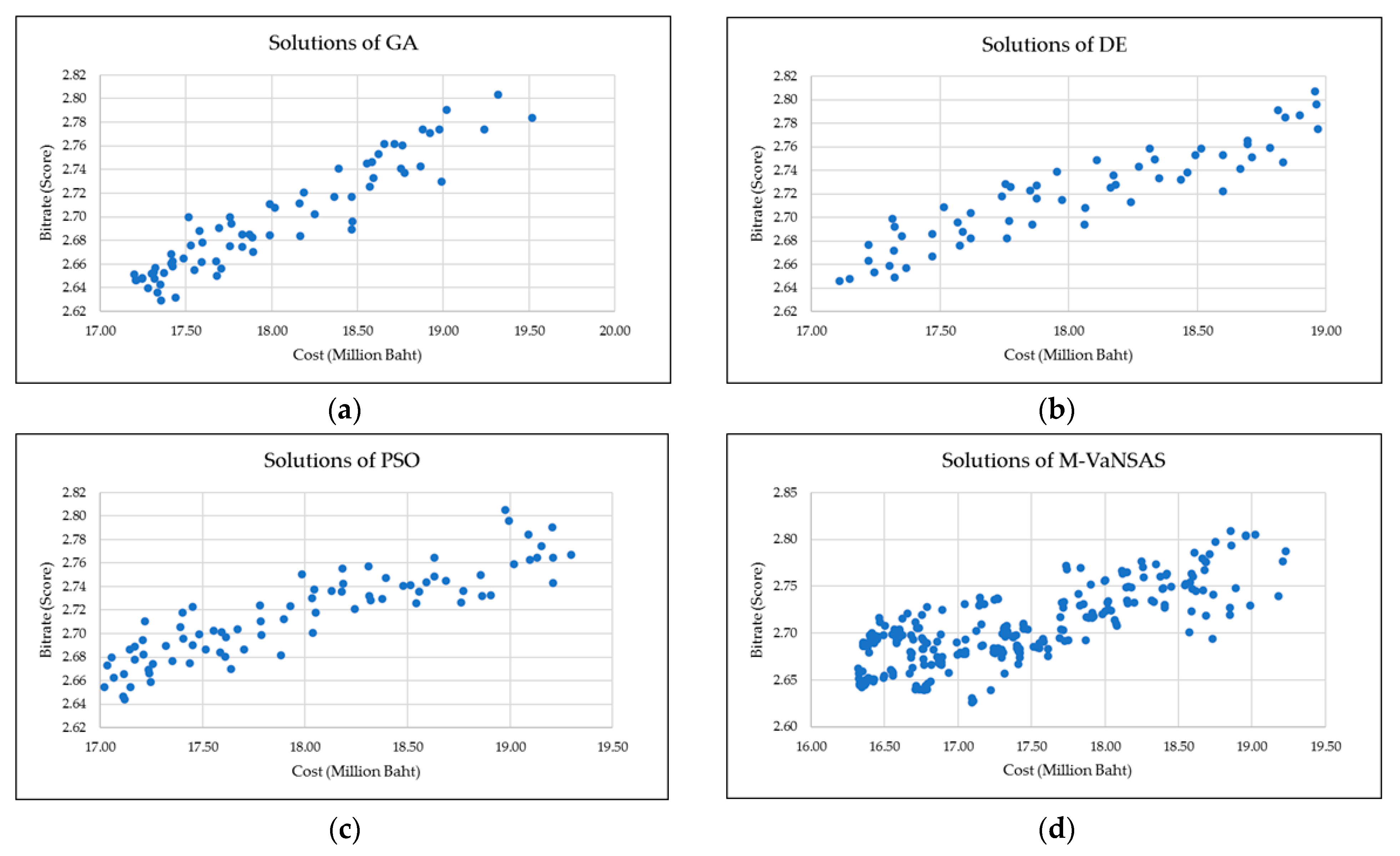
Figure 5, the solutions generated using GA, DE, PSO, and M-VaNSAS were thoroughly analyzed and compared based on their ability to optimize system costs and maximize bitrate.
Figure 5a depicts the solutions obtained using GA,
Figure 5b showcases the solutions of DE,
Figure 5c displays the solutions generated using PSO, and
Figure 5d illustrates the solutions obtained using M-VaNSAS. These figures provide a visual representation of the solutions and allow for a comprehensive comparison of their quality and distribution.
In conclusion, the computational results and framework analysis highlight the strengths and weaknesses of the GA, DE, PSO, and M-VaNSAS algorithms for analyzing the tradeoffs between system costs and bitrate maximization for the optimal selection of gateway locations in LoRaWANs. While each algorithm showed some level of effectiveness, the M-VaNSAS algorithm proved the most successful in achieving optimized solutions that minimize system costs while maximizing bitrate. These findings underscore the significance of developing specialized algorithms tailored to specific problem domains, as they can yield superior results compared to more general optimization algorithms.
5.2. The Pareto Front
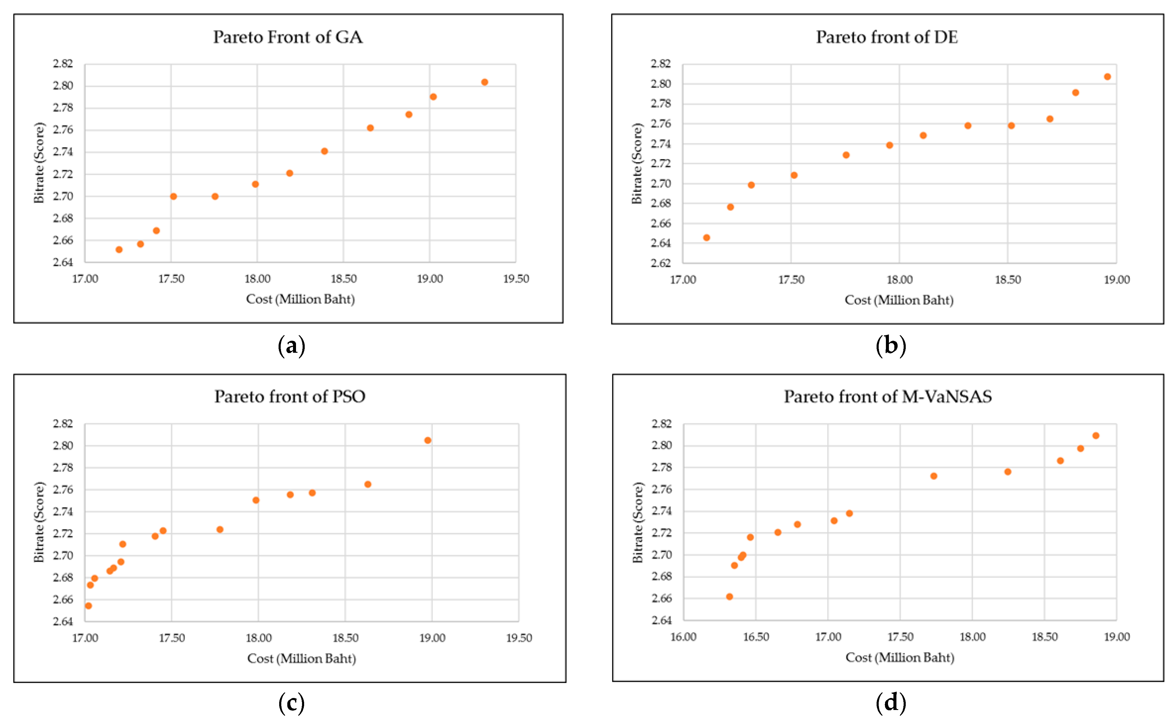
The Pareto front is a set of non-dominated solutions that represent the trade-off between multiple objectives in a multi-objective optimization problem. In this case, the objectives are the cost and bitrate values obtained using different algorithms, namely GA, DE, PSO, and M-VaNSAS. The Pareto fronts of GA, DE, PSO, and M-VaNSAS are shown in
Table 7.
Table 7 presents the Pareto fronts of GA, DE, PSO, and M-VaNSAS. The GA Pareto front consists of 12 solutions with diverse cost and bitrate values, ranging from 17,199,066 to 19,318,163 and 2.652 to 2.803, respectively. These solutions offer a wide range of tradeoffs between cost and bitrate, showcasing the availability of multiple optimal choices. Similarly, the DE Pareto front comprises 12 solutions with cost values spanning from 17,110,691 to 18,958,206 and bitrate values from 2.646 to 2.807, indicating the algorithm’s ability to generate diverse optimal solutions across the cost-bitrate spectrum. The PSO Pareto front showcases 15 solutions with cost values ranging from 17,020,510 to 18,974,922 and bitrate values from 2.654 to 2.805, demonstrating the effectiveness of the PSO algorithm in exploring a broad range of cost and bitrate options. In contrast, the M-VaNSAS Pareto front encompasses 14 solutions with cost values ranging from 16,319,264 to 18,854,515 and bitrate values from 2.662 to 2.809. Remarkably, the proposed M-VaNSAS method outperforms the other algorithms by providing solutions with lower costs and higher bitrates, emphasizing its superior performance. These Pareto fronts are visually represented with graphs in
Figure 6.
Figure 6 depicts the Pareto fronts of GA, DE, PSO, and M-VaNSAS.
Figure 6a showcases the Pareto front achieved using GA,
Figure 6b illustrates the Pareto front of DE,
Figure 6c displays the Pareto front obtained using PSO, and
Figure 6d showcases the Pareto front achieved using M-VaNSAS. Analyzing these Pareto fronts provides valuable insights into the performance of each algorithm in achieving an optimal balance between system costs and bitrate, enabling a comprehensive comparison of their capabilities. The visual representations in
Figure 6 allow for a clear understanding of the tradeoffs and efficiency achieved using each algorithm. Furthermore, a direct comparison of the four Pareto fronts can be observed in
Figure 7, providing a holistic view of their relative performance and effectiveness.
Figure 7 provides a comprehensive comparison of the proposed M-VaNSAS method with GA, DE, and PSO. The comparison reveals that M-VaNSAS exhibits superior performance in terms of both cost and bitrate. The Pareto front of M-VaNSAS showcases a narrower cost range and a wider bitrate range, indicating its ability to achieve more favorable tradeoffs between these objectives. These findings suggest that M-VaNSAS has the potential to outperform GA, DE, and PSO in addressing the optimization problem at hand.
In summary, the analysis of the Pareto fronts underscores the superiority of the proposed method, M-VaNSAS, over GA, DE, and PSO in terms of both cost and bitrate. The algorithm generates a diverse set of optimal solutions characterized by lower cost values and higher bitrate values, demonstrating its effectiveness in achieving superior tradeoffs. The outcomes emphasize the potential effectiveness of M-VaNSAS as a viable strategy in tackling comparable optimization challenges. This is due to the algorithm’s purposeful design for proficiently navigating solution spaces and identifying optimal gateway locations within a black box that integrates various methods, thereby imposing a considerable computational burden. Essential operations involve the execution of black box procedures and the adjustment of pathways based on objective function values. Our methodology involves continuous exploration of pathways within the improvement box, utilizing sophisticated solution enhancement techniques that surpass fundamental local searches.
5.3. TOPSIS Analysis
The Pareto front analysis of M-VaNSAS was further complemented by utilizing the TOPSIS method. TOPSIS involves assigning weights to different criteria to ascertain their relative significance in the decision-making process. The weights, represented by
and
in
Table 8, correspond to the “Costs” and “Bitrate scores” criteria, respectively. The TOPSIS results of M-VaNSAS are presented in
Table 8, providing valuable insights into the performance of the algorithm based on these weighted criteria.
In
Table 8, the TOPSIS results for GA, DE, PSO, and M-VaNSAS showcase the effectiveness of M-VaNSAS, as each of its solutions outperforms the other algorithms. Analyzing the TOPSIS results for M-VaNSAS reveals diverse weight distributions among different solutions, indicating varying importance assigned to the cost and bitrate criteria. For example, Solution 1 assigns a higher weight to the bitrate criterion (
= 0.9) than the cost criterion (
= 0.1). This results in a relatively higher cost (approximately THB 18,854,515) but an impressive bitrate score of 2.809. Similarly, Solution 2 emphasizes the bitrate criterion (
= 0.8) while maintaining a lower cost (around THB 17,734,606) and a slightly reduced bitrate score of 2.772. Interestingly, Solutions 3, 4, 5, 6, and 7 exhibit a consistent weight distribution pattern with varying values, producing comparable cost values (approximately THB 16,464,458) and achieving a reliable bitrate score of 2.716. This suggests that these solutions strike a satisfactory balance between cost efficiency and data transmission quality. Conversely, Solutions 8 and 9 allocate a higher weight to the cost criterion (
= 0.8), resulting in lower cost (around THB 16,353,115) at the expense of a slightly reduced bitrate score of 2.69.
Figure 8 visually presents the TOPSIS results of M-VaNSAS, offering a graphical representation of each solution along with its corresponding characteristics.
Figure 8 visually represents the TOPSIS analysis of M-VaNSAS, depicting the solutions grouped according to their performance. This detailed analysis provides a holistic assessment of the effectiveness of M-VaNSAS for analyzing the tradeoffs between system costs and bitrate maximization for the optimal selection of gateway locations in LoRaWANs and offers valuable insights into the algorithm’s ability to optimize system costs and maximize bitrate. By understanding the grouping and characteristics of these solutions, decision-makers can make informed choices based on their specific priorities and requirements. The analysis provides valuable insights into the tradeoffs between cost and bitrate and enables stakeholders to select the most suitable solution group that aligns with their preferences.
5.4. Optimal Gateway Locations for LoRaWANs
This study conducted a comprehensive comparison of solutions, Pareto fronts, and TOPSIS analyses for DE, GA, PSO, and M-VaNSAS in the context of selecting multiple gateway locations in LoRaWANs. The results emphasized the optimal selection, showcasing a balanced tradeoff between cost and bitrate scores (
= 0.3,
= 0.7). To visually represent the chosen gateway locations, the study leveraged the advanced mapping capabilities of the QGIS (quantum geographic information system) program. This integration of analytical insights and geospatial visualization not only contributes to the advancement of IoT technologies but also facilitates the efficient deployment and management of IoT networks. Notably, the case study focused on a rural area, and results may vary in urban scenarios. In [
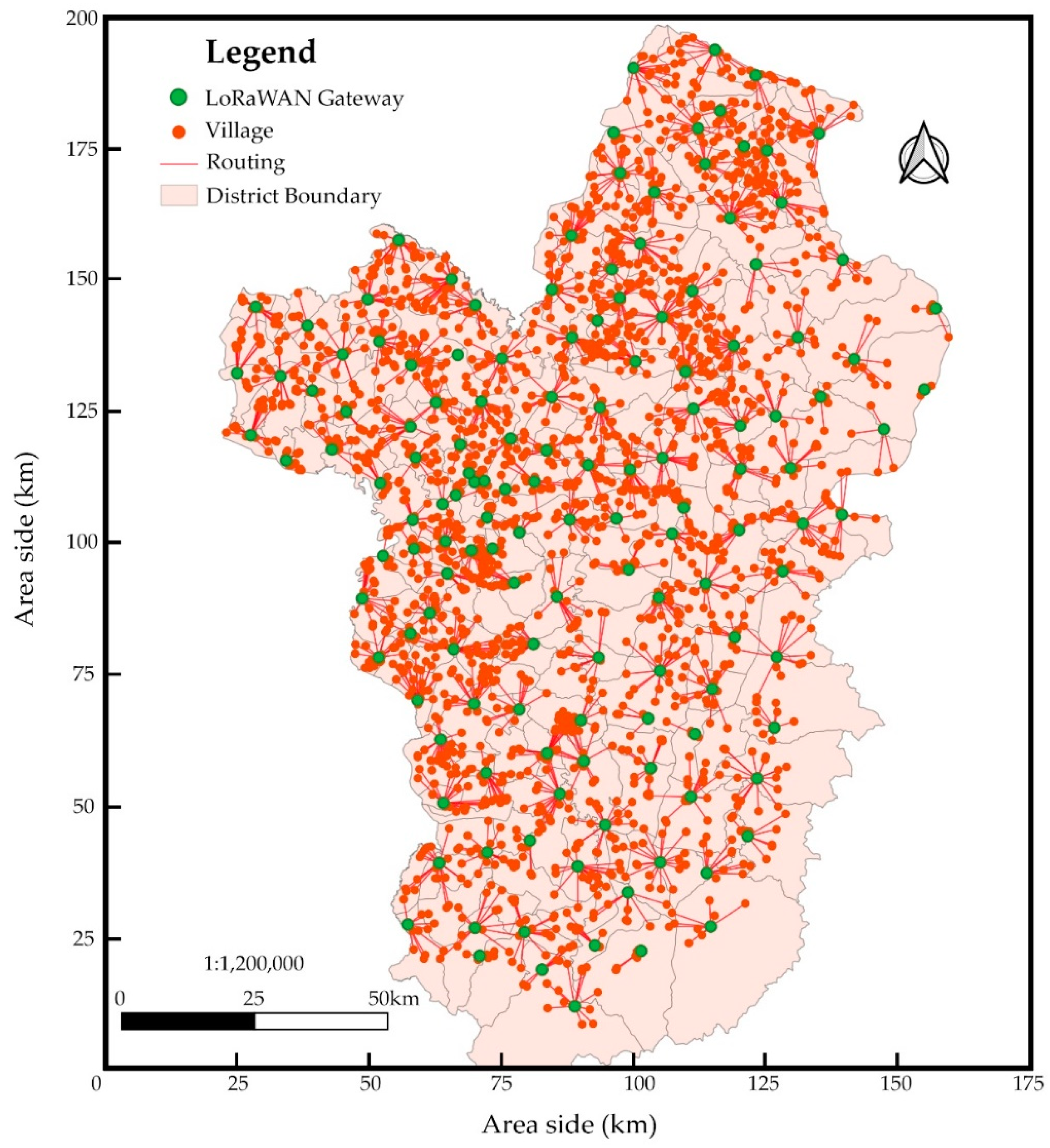
23], it was recommended to evaluate LoRa network performance in diverse environments, including both rural and urban settings. By implementing this approach in the Ubon Ratchathani province, this study provides a comprehensive representation of optimal gateway locations, thereby enhancing connectivity and data transmission in LoRaWANs, as illustrated in
Figure 9.
Figure 9 illustrates the results of a comprehensive analysis aimed at identifying optimal gateway locations for LoRaWANs in the Ubon Ratchathani province. The findings reveal the positions of 144 gateways strategically placed to ensure efficient network infrastructure. These gateways are instrumental in providing reliable LoRaWAN signals to support smart farming initiatives, benefiting a substantial population of 295,942 households spread across 2199 villages. By utilizing the QGIS program’s advanced mapping capabilities, the selected gateway locations are visualized, providing decision-makers and stakeholders valuable insights for infrastructure planning and optimization. This research contributes to the expansion of IoT technologies in agriculture, facilitating the integration of connected devices and enabling farmers to leverage the advantages of smart farming practices, thereby enhancing productivity and sustainability in the region.
6. Conclusions and Future Outlook
This study analyzed tradeoffs between system costs and bitrate maximization for the optimal selection of gateway locations in LoRaWANs. With the development of a mathematical model and the introduction of the M-VaNSAS algorithm, this research makes substantial contributions to the field. It provides valuable insights into the performance of various optimization algorithms and offers an efficient solution to address this complex problem. The computational findings and framework analysis provide evidence of the efficacy of the proposed M-VaNSAS algorithm in comparison to widely used optimization algorithms such as GA, DE, and PSO. The solutions generated using M-VaNSAS consistently outperformed the other algorithms in terms of system costs and bitrate, indicating its ability to strike a favorable balance between these two critical factors. Pareto front analysis further revealed the tradeoffs between system costs and bitrate, with M-VaNSAS offering a wider range of optimal solutions along the Pareto front. Additionally, the TOPSIS analysis provided a comprehensive evaluation of the M-VaNSAS algorithm by assigning weights to different criteria. The results demonstrate its consistent ability to optimize system costs and maximize bitrate, further reinforcing its effectiveness in real-world scenarios. These findings underscore the superiority of M-VaNSAS and its potential for practical implementation in optimizing multiple gateway location selection in LoRaWANs.
In conclusion, this research presented the M-VaNSAS algorithm and conducted a comprehensive comparative analysis. The results highlight its superiority in achieving cost-effective and high-performing LoRaWANs. The insights gained from this study have significant implications for the deployment and operation of IoT applications in various environments. Ultimately, these findings contribute to the advancement of research in network planning and pave the way for improved connectivity and efficient resource utilization in the context of smart city development.
Our research centered on optimizing the positioning of LoRaWAN gateways, utilizing data from a province in Thailand. It is important to note that the limitations of our study pertain specifically to rural areas in Thailand. Future research endeavors should extend their focus to evaluating LoRa network performance in diverse environments, encompassing both rural and urban settings. High mountain areas present challenges to LoRa signal propagation, affecting the performance and efficiency of LoRaWANs. Overcoming these challenges would contribute to advancing the optimization of selecting multiple gateway locations and supporting the overall growth of IoT technologies.


