Article

Symmetric Encryption Relying on Chaotic Henon System for Secure Hardware-Friendly Wireless Communication of Implantable Medical Systems

1
Department of Electrical & Computer Engineering, University of Idaho, 875 Perimeter Drive MS 1023, Moscow, ID 83844, USA
2
Department of Computer & Information Sciences, Temple University, 1925 N. 12th St., Philadelphia, PA 19122, USA
3
Computer Science and Engineering Department, College of Engineering, Qatar University, P.O. Box 2713, Doha, Qatar
*
Author to whom correspondence should be addressed.
J. Sens. Actuator Netw. 2018, 7(2), 21; https://doi.org/10.3390/jsan7020021
Submission received: 7 April 2018 / Revised: 5 May 2018 / Accepted: 8 May 2018 / Published: 11 May 2018

Abstract

:
Healthcare remote devices are recognized as a promising technology for treating health related issues. Among them are the wireless Implantable Medical Devices (IMDs): These electronic devices are manufactured to treat, monitor, support or replace defected vital organs while being implanted in the human body. Thus, they play a critical role in healing and even saving lives. Current IMDs research trends concentrate on their medical reliability. However, deploying wireless technology in such applications without considering security measures may offer adversaries an easy way to compromise them. With the aim to secure these devices, we explore a new scheme that creates symmetric encryption keys to encrypt the wireless communication portion. We will rely on chaotic systems to obtain a synchronized Pseudo-Random key. The latter will be generated separately in the system in such a way that avoids a wireless key exchange, thus protecting patients from the key theft. Once the key is defined, a simple encryption system that we propose in this paper will be used. We analyze the performance of this system from a cryptographic point of view to ensure that it offers a better safety and protection for patients.

1. Introduction

Implantable and Wearable Medical Devices (IMD & WMD) are currently the new trending technologies in personal healthcare systems. They enable efficient diagnostics and easy monitoring of the patient’s health status in real-time and provide more efficient and scalable healthcare by avoiding frequent visits to the healthcare provider. These devices such as cardiovascular medical devices, neurological implants and infusion function medical devices can help control a broad range of body dysfunctions, like diabetes, cardiac arrhythmia, and epilepsy.
Information security is a serious challenge to all of such devices nowadays [1]. Medical devices’ security, particularly for IMDs, is of paramount importance because attacks can be fatal. They do not only steal the private medical data, but they can also affect data integrity and control. IMDs are evolving to provide patients with maximum medical efficiency and safety. The device’s security and the medical records’ privacy are still under development. In fact, IMDs’ architectures usually have limited resources, such as the energy supply, processing power, and storage space. These may require the need of surgeries to overcome some of the limitations. For instance, if we need to resort to surgery in order to change batteries, we have to choose long-life battery types to avoid frequent surgeries. All of these disadvantages render traditional security procedures arduous to implement. Balancing security and confidentiality with the efficiency of the different components is a substantial matter for IMD technologies to advance. For this matter, similar to other systems, IMDs have the following security pillars to protect the patient against attacks:
  • Authentication: Authentication [2] is one of the most common ways to secure two communicating devices. It ensures that both ends communicate with an authentic and legitimate device, not an impersonator. Authentication in IMDs may be directed in two possible ways: through a direct authentication architecture or through an indirect authentication architecture. The indirect scheme introduces a proxy device used to perform authentication protocols, decreasing computation cost and communication overheads in the IMD devices. To identify the device that is requesting a communication, the IMD can use shared keys (temporary or permanent), auxiliary sensors like fingerprint scanners or other biometric signal collectors to identify the unit and to ascertain its authenticity.
  • Cryptography: Cryptography [3,4] relies on shared secret keys to cipher the messages within a given communication. This prevents the understanding of the communication by external eavesdropping devices. Also, cryptography secures any system from any hijacking attempts. The adversary who intercepts a message is not able to perform any significant changes like the modification of the serial number in the aim of a spoofing attack. Nevertheless, standard encrypted communications are still vulnerable to Man-In-The-Middle (MITM) or replay attacks.
  • Anomaly Detection: This technique [5] relies on the observation and the analysis of the received value by the device over time to conclude a pattern. Accordingly, the commands received by the device are estimated to be valid or invalid. For example, in the case of infusion pumps [
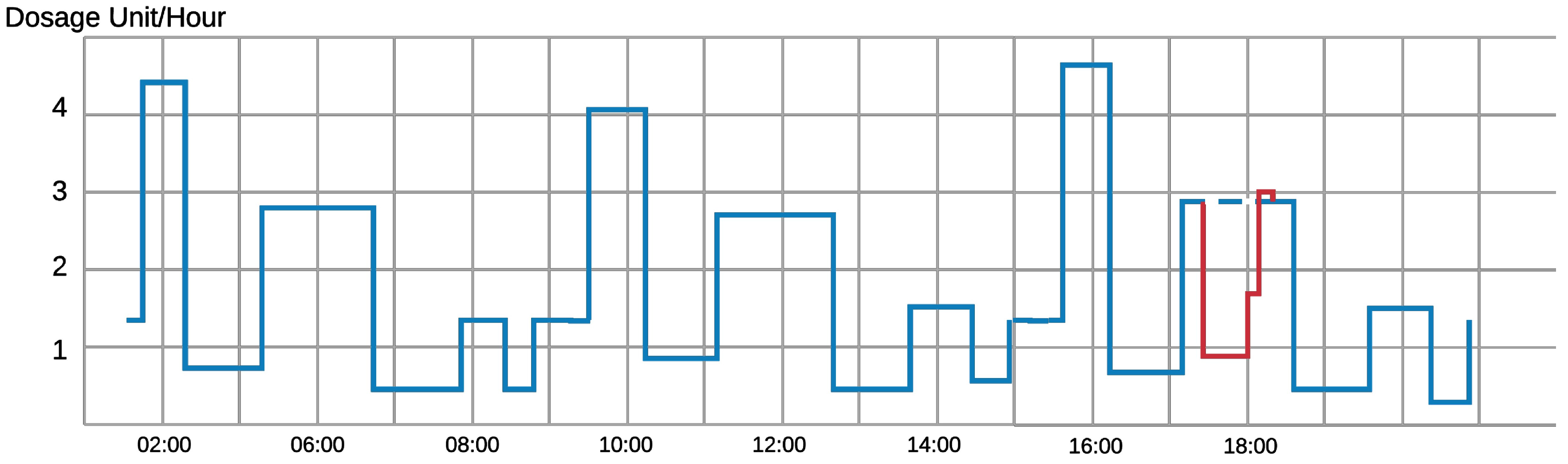
6], the control device monitors and analyzes the infusion rate in the human body over seven to ten days to learn the time and a dosage pattern. This learning approach helps the device to recognize any malicious abnormal command for injection. Therefore, the patient is secured from receiving lethal injections through the IMD. Figure 1 shows an example of a normal injection rate of an infusion device. In the first sixteen hours, we can pinpoint an injection pattern over an eight-hour period. An adversary hijacks the device and prohibits the device from injection around 6 pm (line in red). The device can detect that this prohibition is quite different from what should be injected from the device (dotted blue line) and the anomaly detection algorithm will likely disregard this command.
  • Jamming: Jamming attacks can be used to block any incoming packets to the IMD and block its regular work [7]. Moreover, this technique can be used to prevent other types of attacks on the device, mainly resource depletion and denial of service attacks. Attackers can blast the device with incoming messages, that can lead to a drastic drop in the battery level and overflows of memory and storage. In such scenarios, jamming techniques can be launched from the device itself or from an annexed Wearable External Device. If the device senses the existence of these messages, jamming techniques prevent the device from receiving and treating these packets.
In this work, we intend to protect the IMD wireless communications through developing an efficient encryption scheme. We will design a novel technique to generate pseudo-random keys to be used as cryptographic symmetric keys similar to the work in [8]. This key will be employed to cipher the exchanged packets between the devices used by patients and their doctors. This work does not aim specifically at a specific IMD but tackles any implantable systems that use wireless communications between its devices, e.g., an implanted pacemaker and its external monitoring device [
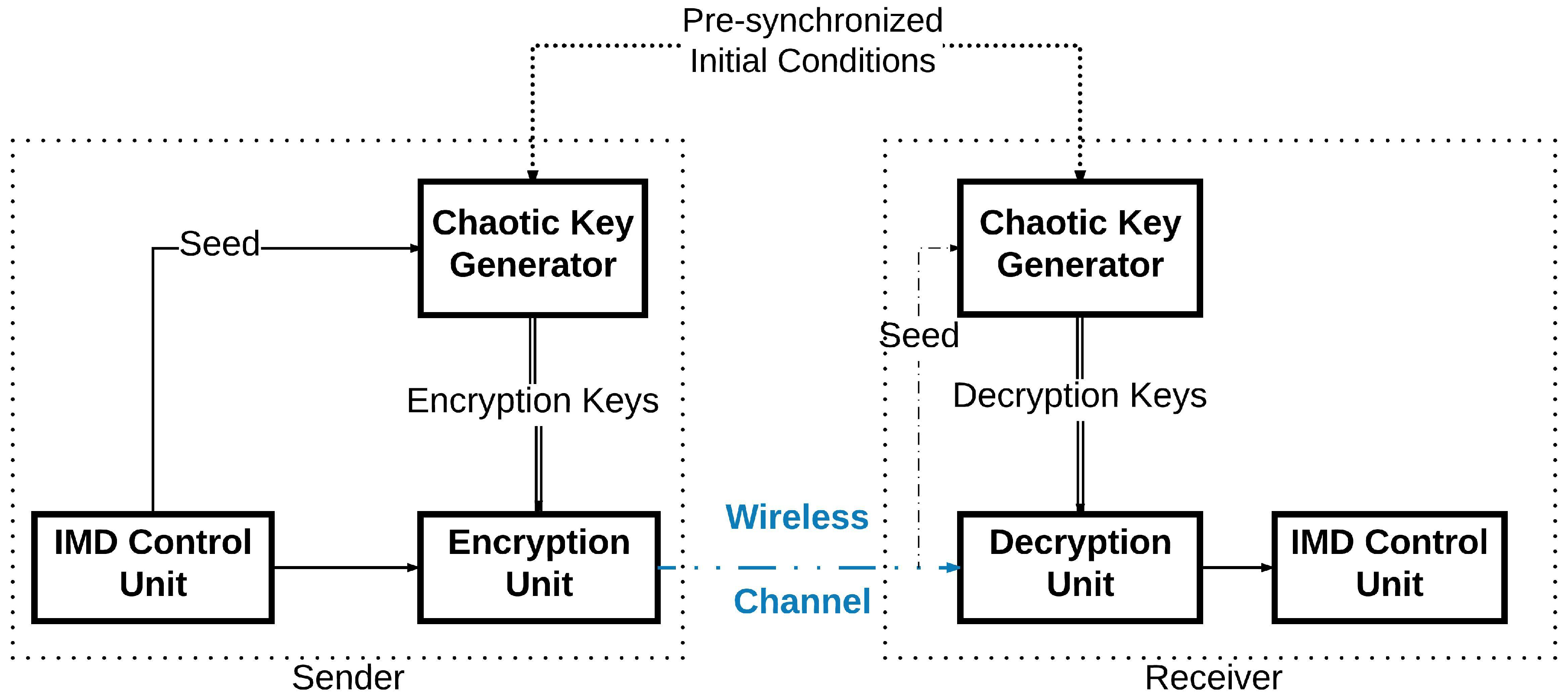
9]. In addition, we also present a new encryption system to protect the wireless communication between the IMDs. In the sender’s device, a key generator will generate an encryption key using a Pseudo-Random Number Generator (PRNG) based on a chaotic system [10]. This key will be applied to cipher the message to be sent by the device. In order for the receiving device to be able to decipher the sent message, it has to generate internally the same encryption key used in the first place. The sender will not communicate the key directly on the wireless channel. The sender needs only to communicate publicly the seed used for its encryption key generation as shown in Figure 2. Even though the seed is thought to be enough to generate the same key, the case of the chaotic system differs: the two devices use the same chaotic generator to deliver the encryption key. However, this pseudo-random generator has two inputs instead of one: the seed and the initial conditions. The initial conditions are already shared between the two devices through a given physical synchronization method. Therefore, when the receiver receives this seed, its internal key generator will be able to generate the right key to be used for deciphering the message it has received. Thus, the wireless communication can take place securely.
Nien et al. [11] explained how it is possible to realize a chaotic system to map a random sequence of numbers. They also detailed how this sequence can encrypt colored images using an XOR operation with the matrix values defining the image. This encryption was applied to digital color images in the context of internet communications, and achieved a high level of security. Bing et al. [12] also showed how to achieve a high performance data encryption using chaotic systems for image ciphering. The chaotic carrier signal they achieved has a strong randomness, a broadband spectrum and was likely unpredictable. Octavio et al. [13] presented in their work a very large scale integration (VLSI) implementation of a precise case of the chaotic encryption schemes. They described a system employing a Lorenz oscillator. This scheme is known for its complexity in hardware implementation, but they overcome it by developing a new Generalized Lorenz System suitable for their case. For the case of Wang et al. [14], they realized an image encryptor based on the high-dimension Lorenz chaotic system and a perceptron model within a neural network, and proved through experimental work the high security of this algorithm and also its strong resistance to the known attack vectors. Guan et al. [15] also introduced a similar encryption system, but they added a position shuffler and a pixel value changer in the grey-mode of an image to strengthen the security of their method. In addition, Liu et al. [16] treated the case of image coloring encryption, where they introduced a bit-level permutation and high-dimension chaotic map to encrypt colored images. They showed afterward through experimental results and security analysis that the scheme is very effective regarding the security of the encryption. Wei et al. [17] introduced an encryption system that has the same goal as the previous one, but uses DNA sequences for the encryption in addition to the chaotic system. Relying on the logic in the DNA sequence, they established a scheme to encode the different color layers of the image in the process. The chaotic map was mainly used to scramble the locations of the different elements. Subsequently, chaotic systems play a major role in enhancing the cryptography field.
In our previous work [18], we developed a new way to generate secure symmetric encryption keys for the IMDs in order to cipher the wireless communication of IMDs. This scheme relies on Henon Map to generate the Pseudo-Random keys, relying on synchronized initial conditions and the cycle seed. As an extension of that work, we designed in this work the full encryption scheme for IMDs and analyzed its performances. Therefore, the main contributions in this paper can be summarized as follows:
  • Analysis of the new symmetric key generation scheme for wireless cryptography based on PRNG derived from a low-dimensional chaotic system.
  • Design of an efficient light-weight block cipher encryption scheme that uses fewer rounds than conventional encryption schemes with short-length keys.
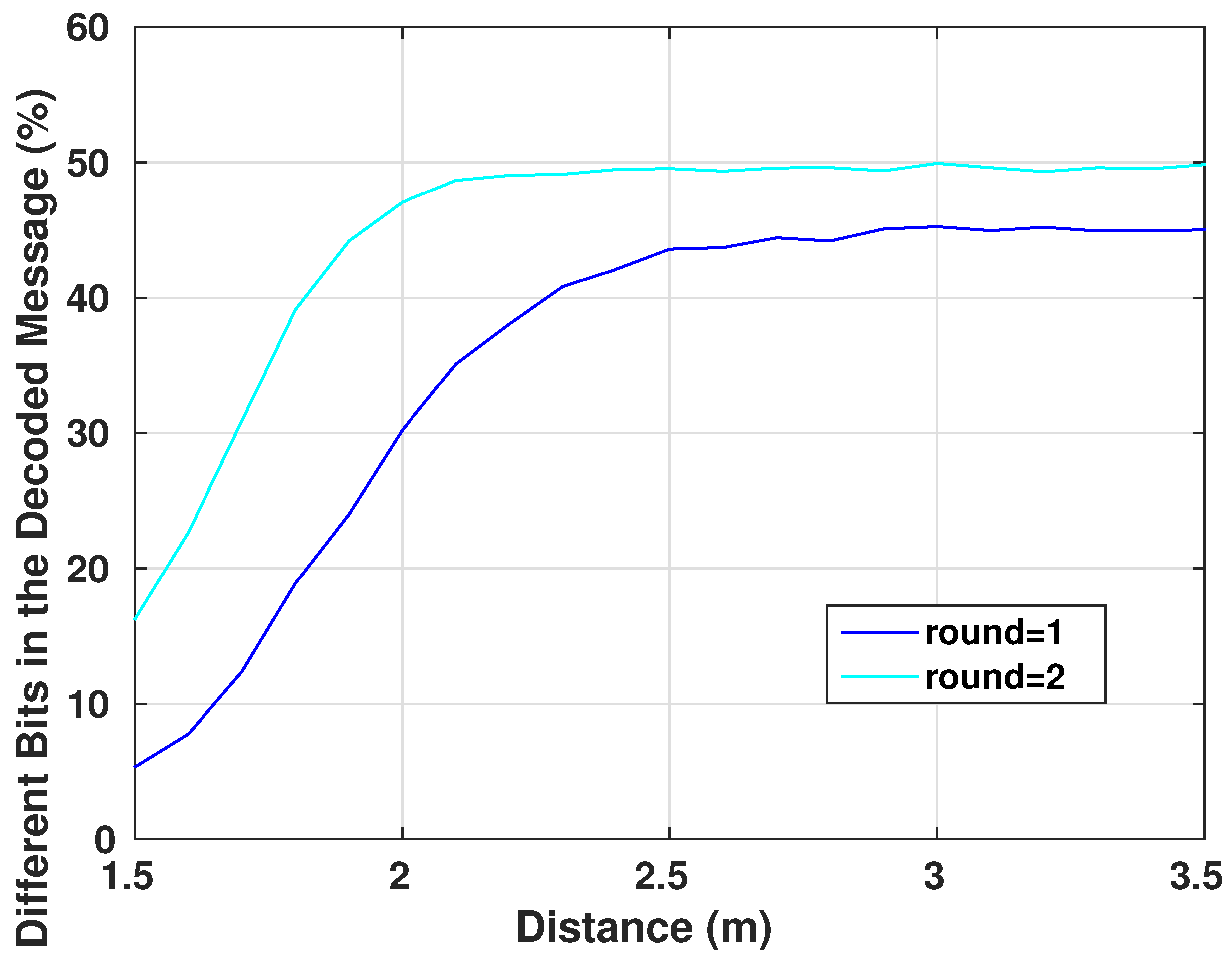
  • Investigation of the encryption scheme within an on-body to off-body communication channel.

2. Low-Dimensional Chaotic System

2.1. Chaotic Systems

Chaotic phenomena are non-linear observations that can be defined by determined systems. They have a great appeal in the security fields essentially for their ideal pseudo-randomness, broad spectrum and their sensitive dependency on their initial conditions [19]. Therefore, research on the chaotic secure communications has been developed extensively [11,20,21]. Chaotic systems are defined as dynamical systems that are characterized by a high sensitivity towards initial conditions and show unpredictable observations from the exterior of the system. This means that the smallest change in the initial conditions of the system can cause an ostensible random and unpredictable behavior of the results; a behavior that nevertheless obeys precise rules [19]. This property is mainly the reason that chaotic systems are introduced to the application of secure communication: when properly used, chaotic systems produce cryptographically secure pseudo-random number generators [22]. In addition, without the right initial conditions, the correct pseudo-random sequence cannot be regenerated.

2.2. Henon Scheme

The standard Henon map is a two-dimensional discrete-time system containing a single quadratic term as non-linearity [23]. This map is known to display chaos for certain parameter values and initial conditions [24]. The Henon map [25] is a simplified model of the Poincare map that emerges from a solution of the Lorenz equations.
The Henon map is expressed as follows:
x n + 1 = 1 a x n 2 + y n y n + 1 = b x n
where a > 0 , b > 0 (bifurcation parameters) [25].
The results of the system depend highly on the initial conditions x 0 and y 0 . To show a chaotic behavior, we use for this system a = 1.4 and b = 0.3 . The choice of these values was in a way such that they are small enough so that x i and y i were folded and do not extend to infinity, but not too small to lose the line structure of the attractor [23]. The attractor of this chaotic system is plotted in Figure 3. We observe that the system points remained inside the trapping quadrilateral and did not escape to infinity. Also, at each iteration, the quadrilateral is pulled and closed by the Henon map until the geometrical attractor is achieved. Disregarding the first points, the following points of the system orbit around the attractor in a random way. This orbiting is very sensitive to the initial conditions, from which came the nomination of a chaotic attractor.

3. Key Generation

Our proposed key generation scheme will only depend on the seed of the generator. This seed, which we will refer to as s t o p _ t i m e , represents the end of the iterations cycle of the Henon system. For security measures, the patient’s medical device will synchronize the initial conditions of the Henon equations using wired links with the trusted device. In addition, they can be pre-implemented in the system’s devices before use. Therefore, the attacker will not have the second needed input to generate the desired key, even if he/she succeeded to eavesdrop the seed. The generation of the key on the device will be simple, however, on the attacker’s device, it is going to be a complicated process. The main device will generate the seed on its side, then it will communicate it to the second end of the system. Afterwards, the encryption key will be generated independently on both sides from the communicated s t o p _ t i m e to be as shown in 
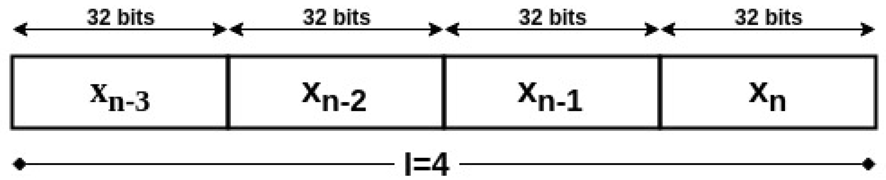
Figure 4. In order to reduce the computation cost of the algorithm, the data values will not be represented on the same number of bits as the key length, but on a fixed point representation of 2Q30 or 2Q14, i.e., the data has 2 bits integer and 30 bits fraction, or 2 bits integer and 14 bits fraction, respectively. This utilization of low precision among the variables of the Henon system will avoid the extra use of memory and computational resources. Hence the low resources of the device would not become a problem for the algorithm execution. The encryption key with length m will then be the concatenation of the last binary l values generated by the Henon equation, such that m = 32 × l or m = 16 × l .
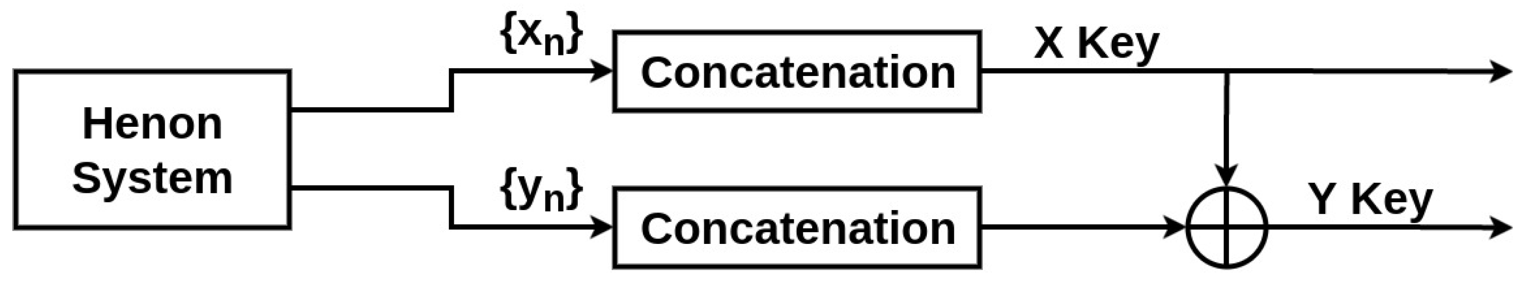
For statistical reasons and to ensure a better security and randomness in the generated keys, the second key Y will be the result of the XOR operation of the raw keys X, and Y generated from the equations as shown in Figure 5.
The seed (or s t o p _ t i m e ) will be generated as a function of the system clock. Another way which is much more secure but more complex, is to use the exclusive characteristics of the wireless channel through the physical layer security to generate a common random seed based on the channel gain or phase [26,27,28,29]. Also, the manufacturer will define a non-short time lapse after which the s t o p _ t i m e (seed) value will expire. When it terminates, a new request with a new value will update the Henon system’s seed of the devices. This contributes to the improvement of the system’s security while lowering the computational costs.

4. Cryptographic Unit System

Common symmetric key encryption standards like Advanced Encryption Standard [30] use long rounds of substitution-permutation network [31] for ciphered messages, along with long keys to enhance their security. For this reason, we design in this work a simple symmetric-key encryption scheme that is not time and memory intensive.

4.1. Diffusion and Confusion Blocks

One of the main goals of encryption systems is that the output is not humanly readable. As in any electronic device, packets communicated wirelessly are a set of 1’s and 0’s. So we aim through this encryption system to prevent any eavesdropper on the communication channel from detecting patterns in different packets allowing them to understand the different parts of the message. For example, if an eavesdropper intercepts different packets and reads them [32], conventionally he/she will know that any message will start with similar headers allocated in the first four or maybe eight bits. Moreover, he/she can notice that packets sent from the same device all have the same set of exactly sixteen bits in the middle. The eavesdropper can conclude then that this is the ID number of the device. On the other hand, a simple XOR operation or a simple bit permutation does not prevent this problem. This bit flipping just makes the analysis harder, as the eavesdropper can deduct from a simple change of a set of bits the original bit location. Once deciphered, the attacker is able to modify the packets and reuse them for his/her own purposes. For this reason, our encryption system focuses on two main properties of secure ciphers [33]:
  • Confusion: which is the property of drastically modifying data from the input to the output. In other words, each bit of the ciphertext should depend on several parts of the system.
  • Diffusion: which is the property responsible for changing many different bits of the output when a single bit of the input is modified.
The combination of these two properties decreases the chance of statistical attacks and analysis to break the cipher.

4.2. Cryptographic Unit

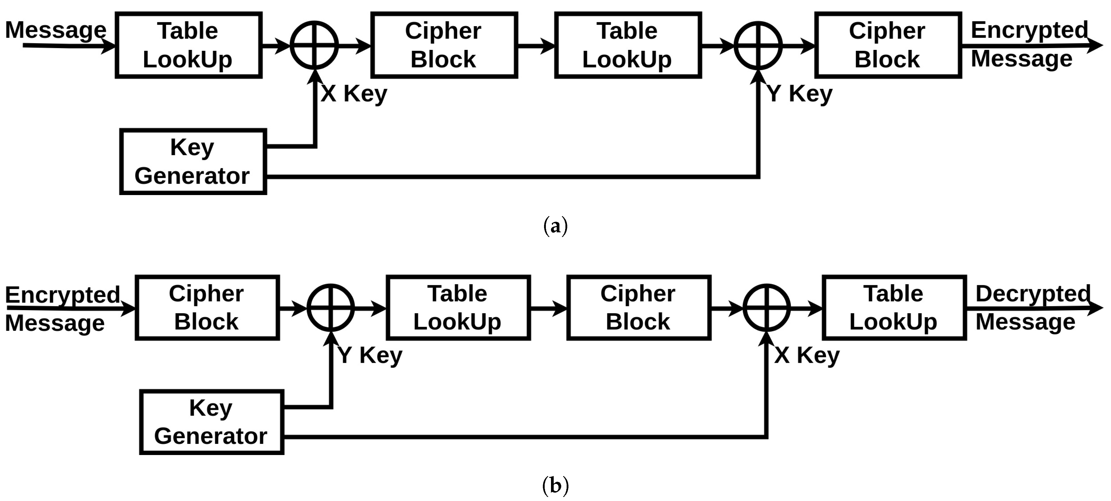
The cryptographic unit is composed of three parts: an XOR operator (a simple operator to hide the communication from simple eavesdropping), a Table LookUp unit and a Cipher block unit (described in Section 4.3.1 and Section 4.3.2). Additionally, it has two inputs incoming from the chaotic generator: the X Key and the Y key. The full scheme of both of the encryption and decryption systems is shown in Figure 6. The original message generated by the device starts by passing through the Table LookUp unit that shuffles the bits. Then, the result is operated with an XOR operation with the X Key. Next, the signal passes through the Cipher block unit. The resulted message re-enter again through the same units in the same order, only this time the XOR operation is achieved with the Y Key. Finally, the encrypted message is generated. The two times reinstantiation of the blocks is the minimal scheme to guarantee a robust cryptographic result. For medical systems with robust computational resources, a loop can be introduced into the system to increase the complexity of the encrypted message.
For the decryption unit, the received encrypted message will get through the same units in a reverse order: the Cipher block is now used in its decryption mode, the Table LookUp unit will reorder the bits in their original positions according to the same function it has in memory (which is synchronized with the order stored in the sending device), and for the XOR operations with the encryption keys, we can get the original message by reapplying the same encryption key as a second operator. This is where the necessity of having the same encryption key on both sides is critical. If there is a looping function in the original encryption unit, the decryption unit should be synchronized with the same number of loops in its algorithm. Therefore, we can regain the original message sent by the first device.

4.3. Featured Blocks

To ensure the properties discussed in the previous paragraph, our system includes the following blocks:

4.3.1. Table LookUp

The objective of this block in the encryption system is to shuffle the different bits in the packet with the single knowledge of the device and the ones synchronized with it. This shuffle will transfer according to a reversible process F each i-th bit to the index j such that
j = F ( i ) i 1 i 2 F ( i 1 ) F ( i 2 )
This shuffle operation will prohibit an eavesdropper from pinpointing the different original bits of the packet to decipher the role of each set of bits in the packets. For example, if an adversary intercepts a packet wirelessly and wants to resend it to the device after changing the ID number within the packet, he/she is unable to know which set of bits in the packet represents the ID tag. This Table LookUp process will enhance the confusion and diffusion characteristics of the full encryption system.
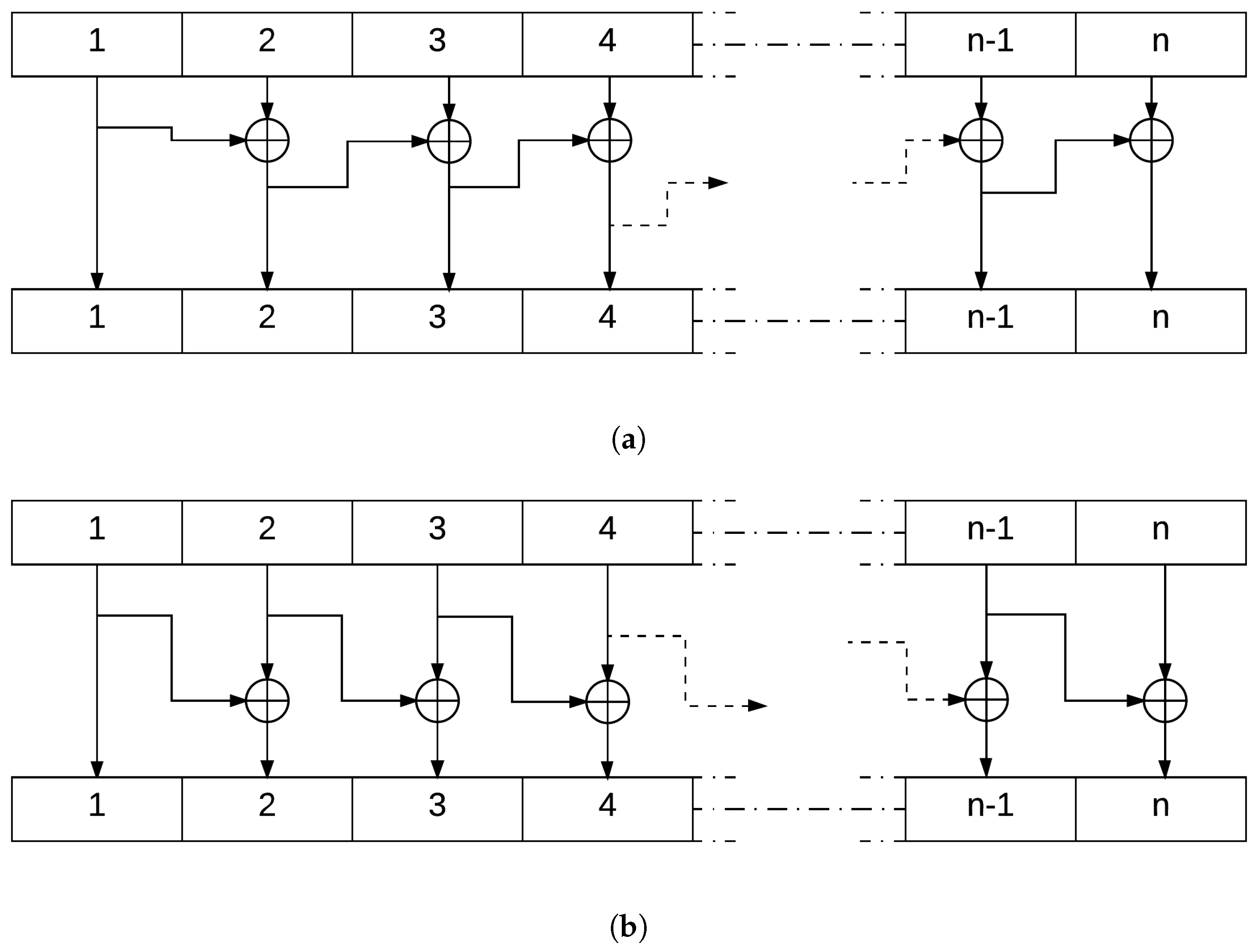
4.3.2. Cipher Block

This block of the encryption system uses the XOR function to generate an output message block where each bit depends on more than one bit from the input. This function is simple to implement and is not of high complexity. Its property where
a b b = a
is the key to decrypt the ciphered text after going through this block. Figure 7 explains in detail this operation.

5. Communication Protocol

The first fundamental step for two devices to communicate securely using wireless communication with this protocol is to have synchronized initial conditions for the chaotic equations. If possible, the best approach to execute this is to synchronize it through a physical connection, as it is the most secure communication method. An alternative is to have these variables already be defined during the manufacturing process. Also, this synchronization applies to the case of the Table LookUp of the encryption unit. The device then starts with a communication request. This request identifies the sender and asks to receive the seed to start the encrypted communication. There is no threat in this step, as even if through spoofing, a third party receiving the seed from the asked device would not be able to establish a secure communication due to the lack of the initial conditions of the chaotic system. Afterwards, the second device generates a seed with its internal algorithm and sends it to the other end. When both devices have the shared seed, they can both use their implemented chaotic system to generate the same pseudo-random key. Therefore, a secure communication can be established. This process will protect the IMDs as it will ensure an encrypted communication, at the same time, the threat of achieving the encryption key by an external third-party is diminished. The devices have individual systems to generate this key, while the process itself has a low cost in the memory and computation process. This prevents the devices from sharing the key wirelessly and insecurely, and also can be programmed to change the encryption key at any needed time. The exchanged messages will include in their segments a Hash [34] segment (Figure 8) that can be simply generated using, for instance, a cyclic redundancy check algorithm [35].
This Hash ensures the integrity of the exchanged message, thus guaranteeing that the message is not modified and the encryption key used is the same one on both ends. The seed is designed to expire. Therefore, there will be a periodic update of the seed. This expiration period will depend mainly on the system, to be a trade-off between performance and security. When the seed expires, the device should request again from the system a seed to be able to maintain the communication. This constant change is resource-friendly regarding the IMD capacities. Also, it ensures that an external party cannot uncover it for two main reasons. First, only one input is being communicated publicly. Second, avoiding the use of the same encryption key will prevent an attacker from analyzing the wireless communication statistically and concluding the possibilities of the key to exploit them. This is where the use of a low dimensional chaotic system is beneficial.

6. Statistical Tests

The security aspects of any encryption system relate highly to the key used in encrypting/decrypting the communicated messages [8]. As the encryption scheme that will be used in our work is symmetric, once the adversary possesses the key, the device becomes vulnerable to multiple types of attacks. Therefore, the key generator should perform like a truly random generator so it cannot be predicted by a third party using statistical or probabilistic approaches. Moreover, pseudo-random numbers generated for cryptographic applications must be unpredictable: if the initial conditions are unknown, the next output bit in the sequence generated cannot be foreseen by the adversary even if he/she possesses any knowledge of the previous random numbers in the sequence.
A set of statistical tests for the randomness of number sequences is described by The National Institute of Standards and Technology (NIST) [36] to ensure that the given random or pseudo-random generator can be used for cryptographic purposes. The described procedures aim to detect any deviation of a given binary sequence from being random which can be due to a poorly designed generator.
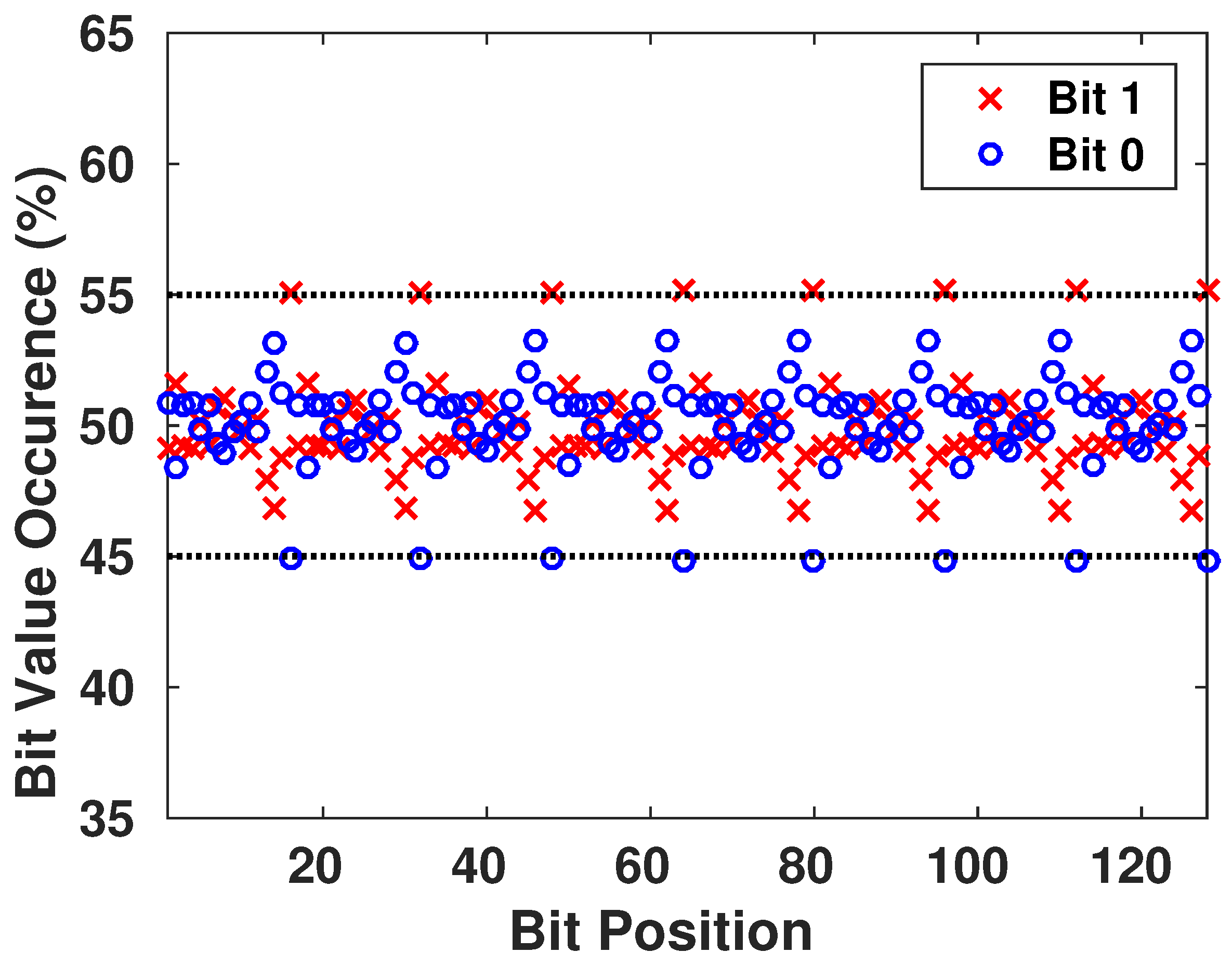
6.1. Monobit Test

This test ensures the randomness of the whole sequence by verifying if the appearance proportions of 0’s and 1’s are approximately the same. Thus, there is not a value that is more probable to appear than the other.
The test assigns a value of 1 to each 0 and a value of 1 to each 1 in the n-bit sequence, then it computes the sum S n into
s o b s = S n n ;
The test passes when P v a l u e = e r f c s o b s 2 > 0.01 , with e r f c ( · ) being the complementary error function. The result is interpreted as follows: if in the sequence there are too many ones or too many zeros, S n will deviate from 0, and large values of S n will lead to a small value of P v a l u e .

6.2. Frequency Test within a Block

This test verifies the proportion of 1’s within M-bit blocks. It determines if the frequency of 1’s in the M-bit block is approximately the same as the frequency of 0, as expected from any random sequence. This test is a general form of the previous test, as the latter falls in this test when M is equal to the total length of the sequence.
The test divides the whole sequence into M-bit blocks, if there are any remaining bits, they are automatically discarded. Then, it computes the proportion π i of 1’s in each block i, and finally,
χ 2 ( o b s ) = 4 M i = 1 N π i 0.5 2 .
The test passes when P v a l u e = i g a m c N 2 , χ 2 ( o b s ) 2 > 0.01 , with N being the number of blocks in the sequence and i g a m c ( · ) being the incomplete gamma function. The result is interpreted nearly as the previous one: a small value of P v a l u e indicates that there is a large deviation from the equal proportion of 1’s and 0’s in at least one of the blocks.

6.3. Runs Test

A run is a continuous sequence of the same bit value. The run should also be bounded with a bit of the opposite value at its start and end. An example of a k _ bit run is:
0 11 111 k bits 0
This test verifies if the number of runs existing in the generated sequence is as expected from a random sequence. In other words, the test verifies if the oscillation between 0’s and 1’s is not too quick or too slow for a random sequence.
The test verifies this oscillation by calculating
v n ( o b s ) = j = 1 n 1 r ( j ) + 1 ;
where
r ( j ) = 0 if b i t j = b i t j + 1 1 otherwise
The test passes when
P v a l u e = e r f c v n ( o b s ) 2 n π ( 1 π ) 2 2 n π ( 1 π ) > 0.01 ;
The result is interpreted as follows: A small value of v n ( o b s ) indicates that the oscillation between 0’s and 1’s in the sequence is too slow to be considered as a random sequence, a large value of v n ( o b s ) indicates that the oscillation is being too quick for a random sequence.

6.4. Test for the Longest Run of Ones in a Block

This test ensures that the length of the longest run of 1’s within the different M-bit blocks of the generated sequence is compatible with the length of the longest run of 1’s expected in a random sequence, with M a pre-set value from the NIST.
The test will compute the longest run k of 1’s in each block, then will categorize the block into categories c i depending on the value of k according to Table 1.
Then it will compute the frequencies of the longest run of the blocks ν i = number of blocks falling in c i . Afterwards, it will calculate
χ 2 ( o b s ) = i = 0 L ( ν i N π i ) 2 N π i ;
where L and N are pre-determined by the NIST as shown in Table 2.
The test passes when P v a l u e = i g a m c L 2 , χ 2 ( o b s ) 2 > 0.01 . The result value being not small shows that the generated sequences have no cluster of 1’s or 0’s.

6.5. Discrete Fourier Transform (Spectral) Test

This test focuses on the peak heights of the Discrete Fourier Transform (DFT) of the generated sequence. It looks in the sequence for periodic features that contradict the assumed randomness of the bit chain.
The test assigns a value of 1 to each 0 and a value of 1 to each 1 in the n-bit sequence and sums it to produce a value X, then it applies the DFT, S = D S T ( X ) . Afterwards, it computes M = S ( first n / 2 bits ) and the peak height threshold T = log 1 0.05 n . Finally, it computes N t = 0.95 n 2 , the expected theoretical number of peaks under the threshold T, and
d = N o N t 0.95 × 0.05 × ( n / 4 ) ;
with N o the actual number of peaks in M that are less than the threshold T.
The test passes when P v a l u e = e r f c d 2 > 0.01 . A low value of d indicates that there were actually too many peaks in M above the threshold T.

7. Statistical Results of The Generated Keys

7.1. NIST Test Results

We evaluated these statistical tests for the different generation of both X and Y keys with length equal to 128 bits for different s t o p _ t i m e values and different initial conditions. Generally, the exchanged packets in such medical devices are small in length. That is why we chose an average of 128 bits for the key length to run the tests on. Table 3 summarizes the test results.

7.2. Pattern Existence

We want to ensure that the generated keys are truly random, and it is statistically impossible for the adversary to generate an authentic key while possessing previously generated keys from the chaotic system. Therefore, we focus on the appearance of each value on all the bits of the key, as shown in Figure 9. Then, we have verified the presence of all the different configurations of a block of s bits to see if there is any pattern that is more probable to appear than others. The result is shown in Figure 10, with blocks having s going from 1 to 8 bits in each configuration.
We conclude that there is no existence of a certain configuration of bits that is more-likely to appear than others. This guarantees the randomness aspect of the generated keys.

8. Key Performance Evaluation

8.1. Sensitivity to the Initial State

The main property and advantage of using chaotic systems to generate pseudo-random keys is their high sensitivity to the initial state of the system. This property is exploited to secure the encrypted messages that are communicated between the devices. Even if the attacker possesses the system’s equations of the generation process, he/she would not be able to achieve the right Pseudo-Random sequence that the device will use. In Figure 11, we observe the sensitivity of the different keys generated for the same s t o p _ t i m e with changes that can reach the order of 10 6 and still affect at least 45–50% of the key bits.
Given the fact that the adversary has no knowledge of the s t o p _ t i m e of the system, the key generated for the encryption is fully random at this point of time. Figure 12 demonstrates the sensitivity of the generator towards the number of iterations to produce the key. This sensitivity is significant as we observe that for each different value in the generating seed, the resulting sequence changes drastically.

8.2. Diffusion of the Encryption System

As explained in Section 4.1, diffusion is one of the main property of a good encryption system. It helps to increase the complexity of the statistical tests that an eavesdropper can perform on intercepted messages, prohibiting him/her from deciphering the format of the communicated packets and its potential contents and values. An eavesdropper cannot modify an intercepted packet and replay it to the system if he/she does not know what are the different parts of the packet and the role of each set of its bits. Figure 13 shows the relation between the number of the different bits of the original message and how they affect the encrypted message. The graph shows the mean value of changed bits in the encrypted message for a given number of bit changes in the original messages. The mean is computed such that the changes in the original messages occur in different bit locations. As we can see, for a slight change in the original message, the encrypted one has more variations in the bit values, even for a single-round algorithm. In fact, using one round in the encryption system is only dedicated to basic IMD that have a basic architecture and very limited resources and where the security aspect is not very demanded. However, this protocol still offers secure communication to the device. Adding an additional round to the encryption system will increase linearly the complexity of the encryption algorithm by a simple factor of two, however, the confusion and diffusion aspect of the system will be very strong. This can be seen from Figure 13. Also, the avalanche factor [37] of the algorithm will reach the value 0.56 0.5 . The value 0.5 is the least requested value for a robust encryption algorithm, this ensures that more than half of the encrypted output will change on a single change of an input message bit. This will ensure that if there is a recognizable pattern in the input messages, the encryption system will scramble the bits in a way that this pattern is lost.
As the problem with any symmetric cryptosystem, the encryption system appears to be too simple to be robust. This a key limitaion for securing the communication. However, this fact is balanced with the robustness of the key and its sharing method. Yet, this is still a general case to define a good balance between the key generation, its expiraton time and the number of rounds of the encryption system. Therefore, a specefic IMD is to be studied individually to ensure such balance. In addition, that is one of our future goals based on this work’s results.
A main concern for the users is the pattern recognition of the messages, as explained in the work of Li et al. [32]. A typical message in IMDs with simple architecture is as shown in Figure 14. Several attempts to eavesdrop an unsecured message can lead to the identification of the flags of the different packets. Thus, the attacker can gain control over the communication. Figure 15 shows that even listening to a communication where messages have a recognizable pattern, this pattern is eliminated after encryption. In fact, Figure 15 demonstrates the change rate of bits after the encryption process of the same message when only one flag changes. Even though the same encryption parameters are used, the eavesdropper cannot pinpoint the patterns of the message, as the bits appear to randomly change all along the fixed-length packet.

8.3. Key Change

The use of the exact keys is essential to retrieve the original message after receiving the encrypted one. Even though it is only used within an XOR operation, the wrong key will result eventually in an invalid message as the Hash will not match the message. The encryption/decryption system depends on both of the keys generated by the chaotic system, so both of them should be known to be able to decrypt the message. Figure 16 shows the number of bits difference between the decrypted message and the original one when using decryption keys with a given number of wrong bits.

8.4. Body Area Communication Scenario

Our system focuses on IMDs, where they will be part of Body Area Networks [38] or using in-vivo (through living organisms) communications [39]. Both scenarios imply that the communicating devices are close to each other, mostly as it will be the case of an in-body to off-body communication. As a matter of fact, the patient’s medical devices will be either controlled by hand or attached/implanted in the body, and while interacting with a doctor, they will be within a one-meter radius area of each other. Thus, no interaction is needed between distant devices. On the other hand, if there is a malicious third-party that intends to hack the system or eavesdrop, it will be quite distant from the target; unless performing a relay attack. Designed to communicate within a short range, the emitted signals from the devices are subject to a meaningful path loss [40] that limits the eavesdropper from intercepting the signal, increasing the probability of receiving erroneous bits in the intercepted packets. To prove this point, we achieved a simulation of the communication scenario between two devices where the first is implanted inside the human body and the second is outside. Body area communications differ from conventional Radio-Frequency (RF) communications due to the human body effect within the channel. Live tissue is a complex frequency-dependent dielectric material with relatively high permittivity and certain conductivity [41]. In this IMD case, the path loss model of the transmitted signal can be modeled with Equation (9) as follows:
P L = A e α d d 0 + S ;
where d 0 is the implant depth with a typical value of 1.5 cm, A is equal to 251 , 188.6 and α is equal to 8.8 m 1 . S represents the shadowing effect of the channel [42].
Most IMDs use only error detection algorithms in their wireless communication [32,43]. Therefore, in order to establish the performance of the encryption scheme on this communication, we will find the Bit Error Rate (BER) as a function of the distance between the two devices. In our scenario, the error probability [42] is:
P b ( γ ¯ ) = 0 P 0 ( γ ) p ( γ ) d γ ;
where γ ¯ represents the average Signal-to-Noise Ratio (SNR), P 0 ( γ ) is the BER in an Additive White Gaussian Noise (AWGN) channel and p ( γ ) is the PDF of γ .
The path loss represents the fraction between the transmitted power P t and the received power P r :
P r = P t P L ;
Therefore, we can define the SNR as a function of the path loss by:
γ = E b N 0 = P r / f b N 0 = P t N 0 f b × 1 P L
where E b is the energy received per bit, N 0 is the thermal noise power spectral density (PSD) and f b is the data rate.
The thermal noise PSD can be expressed as:
N 0 = k B × T a + ( N F 1 ) T 0 ;
where k B is the Boltzmann constant, T a is the human body temperature, T 0 is the environment temperature and N F is the noise figure of the receiving device.
Having that, the PDF of γ is:
p ( γ ) = 1 2 π σ γ exp ( l n γ μ ) 2 2 σ 2 ;
with
μ = l n γ ¯ 1 2 ρ 2 σ d B ;
σ = ρ × σ d B ;
where ρ = l n ( 10 ) 10 and σ d B is the standard deviation of the distribution of the shadow fading.
The result of the simulation is as shown in Figure 17 with parameters [42] as given by Table 4.
As explained earlier, the communication range of these devices is not more than a meter of coverage. This close area is the normal operational range of any device that needs to communicate with the IMD, whether it is the case of an external wearable device or the doctor’s control device. Any distant communicating device can be asserted as a malicious device. This is where the benefit of using body area network communication appears, essentially that the packets transmitted are generally short in length (128–256 bits). Therefore, a communication in a range shorter than one meter is acceptable. Figure 18 shows how the right packet is hard to recover with an increased distance from the victim. Further, this is in the scenario of possessing a similar encryption/decryption system while having the right keys (that are still hard to intercept as explained through Section 7 and Section 8).

9. Hardware Implementation

Our proposed system consists of the implementation of The Henon map system to generate the random keys x and y. This architecture relies on fixed parameters, a and b and has two main blocks: the Cipher block and the Table LookUp. We simulated the proposed architecture of the encryption system, as shown in 
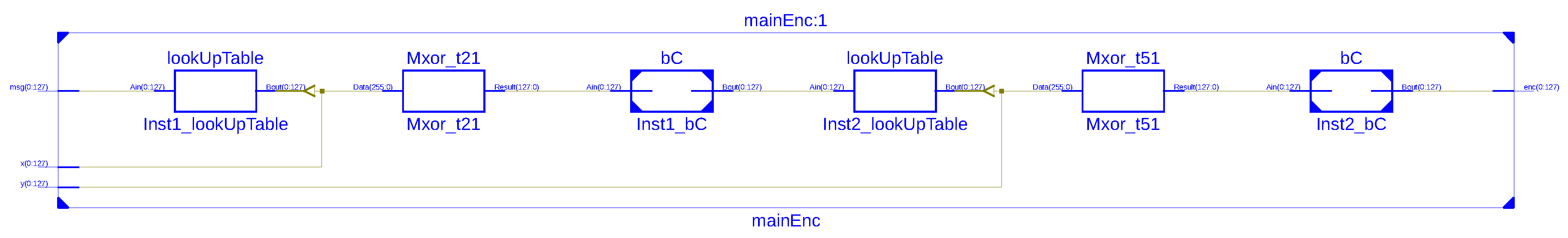
Figure 19, for the correct functional operation with test vectors returned by a software simulation with the VHSIC Hardware Description Language (VHDL). To avoid the problem of VHDL dealing with real numbers for the Henon Map system, as mentioned in Section 3, we implemented the system using a fixed point representation of the real numbers on 32 bits (for the 2Q30 representation) or 16 bits (for the 2Q14 representation). The system has been implemented on Xilinx Spartan-6 [44] using a VHDL structural description. ISE Simulator (ISim) of Xilinx software tools [45] were used to evaluate the hardware resource requirements for our encryption system. The synthesis results after analysis of our system’s implementation are displayed in Table 5 and Table 6, defining the hardware resources regarding Slices/Flip-Flops numbers and the speed performance. The results explain that our encryption system can be effectively implemented for low-resources IMDs. A comparable implementation of the DES algorithm is presented in Table 7.

10. Conclusions

In this paper, we investigated a new scheme to generate securely symmetric encryption keys for IMDs with the aim to cipher the communication wireless packets. We introduced the chaotic system implemented for generating the keys. This system relies on Henon mapping to form the pseudo-random keys, relying on the synchronized initial conditions. The generation is based on a shared seed between the devices to create the same cryptographic key at both ends. This key is used in a simple encryption scheme that explores the path loss characteristics of the channel to create a diffusion effect in the sent packets, hardening the adversary’s task to understand and/or intercept the communication. We then analyzed in a further step the randomness of this pseudo-random generator, ensuring that the generated keys are cryptographically random and impossible to guess in a statistical approach. We have also evaluated the security performance of the encryption system while ensuring its hardware efficiency regarding IMDs. We concluded that the proposed system can be used by any implantable medical device, and can ensure users’ secure wireless communication while protecting them from intruders.

Author Contributions

Conceptualization, T.B. and M.G.; Methodology, T.B. and X.D.; Formal Analysis, T.B.; Resources, M.G. and A.M.; Visualization, A.M. and A.K.A.-A.; Writing-Original Draft Preparation, T.B. and X.D.; Writing-Review & Editing, A.M., A.K.A.-A. and M.G.

Acknowledgments

This publication was made possible by NPRP grant #8-408- 2-172 from the Qatar National Research Fund (a member of Qatar Foundation). The statements made herein are solely the responsibility of the authors.

Conflicts of Interest

The founding sponsors had no role in the design of the study; in the collection, analyses, or interpretation of data; in the writing of the manuscript, and in the decision to publish the results.

References

  1. Denning, D.E. Information Warfare and Security; Addison-Wesley: Boston, MA, USA, December 1998. [Google Scholar]
  2. Wu, L.; Du, X.; Guizani, M.; Mohamed, A. Access Control Schemes for Implantable Medical Devices: A Survey. IEEE Internet Things J. 2017, 4, 1272–1283. [Google Scholar] [CrossRef]
  3. Kumar, P.; Lee, H.J. Security Issues in Healthcare Applications Using Wireless Medical Sensor Networks: A Survey. Sensors 2012, 12, 55–91. [Google Scholar] [CrossRef] [PubMed]
  4. Du, X.; Guizani, M.; Xiao, Y.; Chen, H.H. A Routing-Driven Elliptic Curve Cryptography based Key Management Scheme for Heterogeneous Sensor Networks. IEEE Trans. Wirel. Commun. 2009, 8, 1223–1229. [Google Scholar] [CrossRef]
  5. Zhang, M.; Raghunathan, A.; Jha, N.K. MedMon: Securing Medical Devices Through Wireless Monitoring and Anomaly Detection. IEEE Trans. Biomed. Circuits Syst. 2013, 7, 871–881. [Google Scholar] [CrossRef] [PubMed]
  6. Rathore, H.; Mohamed, A.; Al-Ali, A.; Du, X.; Guizani, M. A Review of Security Challenges, Attacks and Resolutions for Wireless Medical Devices. In Proceedings of the 2017 13th International Wireless Communications and Mobile Computing Conference (IWCMC), Valencia, Spain, 26–30 June 2017. [Google Scholar]
  7. Law, Y.W.; Palaniswami, M.; van Hoesel, L.; Doumen, J.; Hartel, P.; Havinga, P. Energy-Efficient Link-Layer Jamming Attacks against Wireless Sensor Network MAC Protocols. ACM Trans. Sens. Netw. 2009, 5. [Google Scholar] [CrossRef]
  8. Vaudenay, S. A Classical Introduction to Cryptography; Springer: New York, NY, USA, 2005. [Google Scholar]
  9. Halperin, D.; Heydt-Benjamin, T.S.; Ransford, B.; Clark, S.S.; Defend, B.; Morgan, W.; Fu, K.; Kohno, T.; Maisel, W.H. Pacemakers and implantable cardiac defibrillators: Software radio attacks and zero-power defenses. In Proceedings of the IEEE Symposium on Security and Privacy, 2008 (SP 2008), Oakland, CA, USA, 18–22 May 2008. [Google Scholar]
  10. Pecora, L.M.; Carroll, T.L. Driving systems with chaotic signals. Phys. Rev. A 1991, 44. [Google Scholar] [CrossRef]
  11. Nien, H.H.; Huang, C.K.; Changchien, S.K.; Shieh, H.W.; Chen, C.T.; Tuan, Y.Y. Digital color image encoding and decoding using a novel chaotic random generator. Chaos Solitons Fractals 2007, 32, 1070–1080. [Google Scholar] [CrossRef]
  12. Bing, Q.; Liang-rui, T.; Jing, L.; Yi, S. A new chaotic secure communication system. In Proceedings of the 2nd International Conference on Wireless, Mobile and Multimedia Networks, Beijing, China, 12–15 October 2008. [Google Scholar]
  13. Gonzales, O.A.; Han, G.; de Gyvez, J.P.; Sanchez-Sinencio, E. Lorenz-based chaotic cryptosystem: A monolithic implementation. IEEE Trans. Circuits Syst. I Fundam. Theory Appl. 2000, 47, 1243–1247. [Google Scholar] [CrossRef]
  14. Wang, X.Y.; Yang, L.; Liu, R.; Kadir, A. A chaotic image encryption algorithm based on perceptron model. Nonlinear Dyn. 2010, 62, 615–621. [Google Scholar] [CrossRef]
  15. Guan, Z.H.; Huang, F.; Guan, W. Chaos-based image encryption algorithm. Phys. Lett. A 2005, 346, 153–157. [Google Scholar] [CrossRef]
  16. Liu, H.; Wang, X. Color image encryption using spatial bit-level permutation and high-dimension chaotic system. Opt. Commun. 2011, 248, 3895–3903. [Google Scholar] [CrossRef]
  17. Wei, X.; Guoa, L.; Zhanga, Q.; Zhanga, J.; Lian, S. A novel color image encryption algorithm based on DNA sequence operation and hyper-chaotic system. J. Syst. Softw. 2012, 85, 290–299. [Google Scholar] [CrossRef]
  18. Belkhouja, T.; Mohamed, A.; Al-Ali, A.K.; Du, X.; Guizani, M. Light-weight encryption of wireless communication for implantable medical devices using henon chaotic system (invited paper). In Proceedings of the International Conference on Wireless Networks and Mobile Communications (WINCOM), Rabat, Morocco, 1–4 November 2017. [Google Scholar]
  19. Short, K.M. Unmasking a modulated chaotic communications scheme. Int. J. Bifurcat Chaos 1995, 6. [Google Scholar] [CrossRef]
  20. Li, H.J.; Chern, J.L. Coding the chaos in a semiconductor diode for information transmission. Phys. Lett. A 1995, 206, 217–221. [Google Scholar] [CrossRef]
  21. Yu, Y.H.; Kwak, K.; Lim, T.K. Secure communication using small time continuous feedback. Phys. Lett. A 1995, 197, 311–315. [Google Scholar] [CrossRef]
  22. Menezes, A.J.; van Oorschot, P.C.; Vanstone, S.A. Handbook of Applied Cryptography; CRC Press: Boca Raton, FL, USA, 2001. [Google Scholar]
  23. Henon, M. A Two-Dimensional Mapping with a Strange Attractor. Commun. Math. Phys. 1976, 50, 69–77. [Google Scholar] [CrossRef]
  24. Richter, H. The generalized Henon maps: Examples for higher-dimensional chaos. Int. J. Bifurcation Chaos 2002, 12. [Google Scholar] [CrossRef]
  25. Al-Shameri, W.F.H. Dynamical Properties of the Hénon Mapping. Int. J. Math. Anal. 2012, 6, 2419–2430. [Google Scholar]
  26. Xiao, L.; Greenstein, L.; Mandayam, N.; Trappe, W. Fingerprints in the Ether: Using the Physical Layer for Wireless Authentication. In Proceedings of the IEEE International Conference on Communications, Glasgow, UK, 24–28 June 2007. [Google Scholar]
  27. Xiao, Y.; Chen, H.H.; Du, X.; Guizani, M. Stream-based Cipher Feedback Mode in Wireless Error Channel. IEEE Trans. Wirel. Commun. 2009, 8, 622–626. [Google Scholar] [CrossRef]
  28. Du, X.; Xiao, Y.; Guizani, M.; Chen, H.H. An Effective Key Management Scheme for Heterogeneous Sensor Networks. Ad Hoc Netw. 2007, 5, 24–34. [Google Scholar] [CrossRef]
  29. Cheng, Y.; Fu, X.; Du, X.; Luo, B.; Guizani, M. A lightweight live memory forensic approach based on hardware virtualization. Inf. Sci. 2017, 379, 23–41. [Google Scholar] [CrossRef]
  30. Beierle, C.; Jovanovic, P.; Lauridsen, M.M.; Leander, G.; Rechberger, C. Analyzing Permutations for AES-like Ciphers: Understanding Shift Rows. In Proceedings of the Conference: Topics in Cryptology (CT-RSA), San Francisco, CA, USA, 20–24 April 2015. [Google Scholar]
  31. Van Tilborg, H.C.A.; Jajodia, S. Encyclopedia of Cryptography and Security; Springer: New York, NY, USA, 2005. [Google Scholar]
  32. Li, C.; Raghunathan, A.; Jha, N.K. Hijacking an Insulin Pump: Security Attacks and Defenses for a Diabetes Therapy System. In Proceedings of the IEEE 13th International Conference on e-Health Networking, Applications and Services, Columbia, MO, USA, 13–15 June 2011. [Google Scholar]
  33. Shannon, C. Communication Theory of Secrecy Systems. Bell Syst. Tech. J. 1949, 28, 656–715. [Google Scholar] [CrossRef]
  34. National Institute of Standards and Technology. The Keved-Hash Message Authentication Code; Federal Information Processing Standards Publication; NIST: Gaithersburg, MD, USA, 2001.
  35. Ray, J.; Koopman, P. Efficient High Hamming Distance CRCs for Embedded Networks. In Proceedings of the International Conference on Dependable Systems and Networks, Philadelphia, PA, USA, 25–28 June 2006. [Google Scholar]
  36. National Institute of Standards and Technology. A Statistical Test Suite for Random and Pseudorandom Number Generators for Cryptographic Applications; National Institute of Standards and Technology: Gaithersburg, MD, USA, 2010.
  37. Vergili, I.; Yücel, M. Avalanche and Bit Independence Properties for the Ensembles of Randomly Chosen nxn S-Boxes. Turk. J. Electr. Eng. 2001, 9, 137–145. [Google Scholar]
  38. Otto, C.; Milenkovic, A.; Sanders, C.; Jovanov, E. System Architecture of a Wireless Body Area Sensor Network for Ubiquitous Health Monitoring. J. Mob. Multimed. 2006, 1, 307–326. [Google Scholar]
  39. Demir, A.F.; Ankaralı, Z.E.; Abbasi, Q.H.; Liu, Y.; Qaraqe, K.; Serpedin, E.; Arslan, H.; Gitlin, R.D. In Vivo Communications: Steps Toward the Next Generation of Implantable Devices. IEEE Veh. Technol. Mag. 2016, 11, 32–42. [Google Scholar] [CrossRef]
  40. Yazdandoost, K.Y.; Sayrafian-Pour, K. IEEE P802.15-08-0780-09-0006 Channel Model for Body Area Network (BAN); IEEE: New York, NY, USA, 2009. [Google Scholar]
  41. Cotton, S.L.; Scanlon, W.G. A Statistical Analysis of Indoor Multipath Fading for a Narrowband Wireless Body Area Network. In Proceedings of the IEEE International Symposium on Personal, Indoor and Mobile Radio Communications, Helsinki, Finland, 11–14 September 2006. [Google Scholar]
  42. Wang, J.; Wang, Q. Body Area Communications: Channel Modeling, Communication Systems, and EMC; IEEE Press: New Yor, NY, USA, 2013. [Google Scholar]
  43. Marin, E.; Singele, D.; Yang, B.; Verbauwhede, I.; Preneel, B. On the Feasibility of Cryptography for a Wireless Insulin Pump System. In Proceedings of the Sixth ACM Conference on Data and Application Security and Privacy, New Orleans, LA, USA, 9–11 March 2016. [Google Scholar]
  44. Xilinx. Spartan-6 Family Overview; Xilinx: San Jose, CA, USA, 2011. [Google Scholar]
  45. Xilinx. ISim User Guide; Xilinx: San Jose, CA, USA, April 2012. [Google Scholar]
Figure 1. Daily Dosage Monitoring of an Infusion Device of a Patient.
Jsan 07 00021 g001
Figure 2. Block Diagram of the Communication between the Devices with the Cryptographic System.
Jsan 07 00021 g002
Figure 3. Henon Attractor for x 0 = 0.1 and y 0 = 0.1 .
Jsan 07 00021 g003
Figure 4. Example of 128-bit Encryption Key using 2Q30 Data Representation with a s t o p _ t i m e = n.
Jsan 07 00021 g004
Figure 5. Generation of the Encryption Keys from the Henon System.
Jsan 07 00021 g005
Figure 6. Encryption/Decryption System: (a) Encryption Mode; (b) Decryption Mode.
Jsan 07 00021 g006
Figure 7. Scheme of the blockCipher Operation in both (a) Encryption and (b) Decryption Mode.
Jsan 07 00021 g007
Figure 8. Hashing Scheme.
Jsan 07 00021 g008
Figure 9. Frequency Appearance of 0’s and 1’s in the Generated Keys.
Jsan 07 00021 g009
Figure 10. Frequency of Occurrence of Different Length-Blocks of Bits in the Generated Keys.
Jsan 07 00021 g010aJsan 07 00021 g010b
Figure 11. Sensitivity of Key Bits towards the Initial Conditions Variation. (a) Initial value difference in order of 10 2 ; (b) Initial value difference in order of 10 6 .
Jsan 07 00021 g011
Figure 12. Sensitivity of Key Bits towards the Length of the Iteration Cycle.
Jsan 07 00021 g012
Figure 13. Encryption of Different Messages of 128 bit Length.
Jsan 07 00021 g013
Figure 14. Example of a Typical Message Flags of 128 bit Length.
Jsan 07 00021 g014
Figure 15. Bit Change Rate of the Packet When Only Flag Changes. (a) Eavesdropping 10 Different Messages; (b) Eavesdropping 50 Different Messages; (c) Eavesdropping 100 Different Messages.
Jsan 07 00021 g015
Figure 16. Change in Key Bits of 128 bit Length.
Jsan 07 00021 g016
Figure 17. BER performace for in-body to off-body UWB static shadow fading ( σ d B = 10 dB ) communication channel.
Jsan 07 00021 g017
Figure 18. Erroneous Bits in the Decrypted Received Message of 128 bit Length.
Jsan 07 00021 g018
Figure 19. Hardware Schematic of the Encryption Block.
Jsan 07 00021 g019
Table 1. The k values according to the block lengths.
c i M = 8 M = 16
c 0 k 1 k 4
c 1 k = 2 k = 5
c 2 k = 3 k = 6
c 3 k 4 k = 7
c 4 k = 8
c 5 k 9
Table 2. The pre-set values of M, L and N according to NIST.
MLN
8316
128549
Table 3. Statistical Test Results.
Test NameX KeyY Key
Monobit TestPassPass
Frequency within a blockPassPass
Run TestPassPass
Longest RunPassPass
DFT (Spectral)PassPass
Table 4. Parameter Values Used in the Simulation.
ParameterValue
P t −2.55 dBm
T a 310 K
T 0 300 K
N F 6 dB
f b 10 Mbps
Table 5. Implementation Design Summary of a 128-bits Key Generator.
DeviceSummaryDesign
Number of occupied Slices18out of1430
Number of Slice Register51out of54,576
Number of Slice LUTs464out of27,288
IO Utilization68
Table 6. Implementation Design Summary of the Encryption System using a 128-bits Encryption Key.
DeviceSummaryDesign
Number of occupied Slices18out of1430
Number of Slice Register40out of11,440
Number of Slice LUTs60out of5720
Number of fully used LUT-Flip Flop pairs39out of61
Table 7. Implementation Design Summary of the DES Algorithm.
DeviceSummaryDesign
Number of occupied Slices300out of1430
Number of Slice Register840out of11,440
Number of Slice LUTs514out of5720
Number of fully used LUT-Flip Flop pairs98out of61

