
Testing of the N2O/HDPE Vortex Flow Pancake Hybrid Rocket Engine with Augmented Spark Igniter

Faculty of Mechanical Engineering and Robotics, AGH University of Science and Technology, 30-059 Cracow, Poland
*
Author to whom correspondence should be addressed.
Aerospace 2023, 10(8), 727; https://doi.org/10.3390/aerospace10080727
Submission received: 19 June 2023
/
Revised: 8 August 2023
/
Accepted: 15 August 2023
/
Published: 20 August 2023
(This article belongs to the Special Issue Green Propulsion: Present Solutions and Perspectives for Powering Environmentally Friendly Space Missions)
Abstract
:The paper is part of the research aimed at determining if the vortex flow pancake (VFP) hybrid rocket engine is feasible as green in-space chemical propulsion. The objective of this study is to test an N2O/HDPE VFP hybrid ignited with N2O/C3H8 torch igniter. The N2O is used in self-pressurizing mode, which results in two-phase flow and varying inlet conditions, thus better simulating real in-space behavior. The study begins with characterizing the torch igniter, followed by hot-fire ignition tests of the VFP. The results allow for the improved design of the torch igniter and VFP hybrid. The axial regression rate ballistic coefficients are reported for the N2O/HDPE propellants in the VFP configuration.
1. Introduction
1.1. Hybrid Rocket Engines for In-Space Applications
Space industry interest has surged recently with intensified activities in Low Earth Orbit and plans for deeper space exploration. Lower launch costs and innovative business models have given rise to a spike in the number of small satellites launched into orbit. As a result, there is a growing demand for dedicated propulsion systems balancing size, power consumption, safety, and handling.
Most of these small satellites rely on electric propulsion technologies, which generally outperform chemical propulsion in terms of total impulse. However, they lack the thrust needed for rapid maneuvers, leading to a renewed focus on chemical propulsion.
Chemical propellants like LMP-103S and AF-M315E, which were developed as less toxic alternatives to hydrazine, have been successfully used in space missions like NASA’s Green Propellant Infusion Mission and Prisma [1,2]. However, these ionic liquid-based propellants, while less toxic than hydrazine, are not environmentally friendly and are harmful to organic tissue. Ionic liquid-based propellants also require catalyst bed preheating to more than 340–370 °C due to their high-water content, as pointed out by Whitmore [3]. This preheating requirement increases system complexity, dry mass, and power consumption, making them unsuitable for small spacecraft. For instance, the ECAPS 1N LMP-103S thruster needs around 5–7 kJ of energy for startup [4]. In the Prisma mission, the single thruster’s startup required more than 16 kJ of total energy.
Hybrid rocket engines (HREs) conventionally employ a solid fuel grain housed in the combustion chamber, while the oxidizer, which can be liquid or gaseous, is kept in an external tank. This separation of propellants makes handling and operations safer than solid rocket motors. Additionally, a single liquid propellant makes the hydraulic feed system less complex than its bipropellant counterparts, contributing to the relative simplicity of HREs regarding mechanical design. These engines can also deliver specific impulse performance that sits between that of solid propellants and bipropellants. Moreover, HREs allow for throttle control, shutdown, or even restart, making them an attractive choice for spacecraft considering their balance of cost, complexity, reliability, and performance.
Contrasting with the mentioned chemical propulsion of reduced toxicity, HREs can utilize stable, safe, and low-cost propellants like nitrous oxide (N2O) or GOX as an oxidizer and High-Density Polyethylene (HDPE) as fuel. These propellants are largely inert, and the oxidizers used are safe to handle and compatible with most materials. Performance-wise, HREs can provide specific impulses similar to top-tier non-cryogenic bipropellants (>300 s), surpassing ADN or HAN-based monopropellants by over 30%. Furthermore, HRE propellants can be stored over a wide temperature spectrum, while reduced toxicity propellants must maintain a temperature above 0 °C to avoid freezing or precipitation.
Though much of the work concerning hybrids is aimed at larger applications such as sounding rockets and small launch vehicles, recent research explores using HRE as a space thruster for different missions, including upper stages [5,6], geostationary satellite orbit insertion [7], deep space exploration [8,9], and Mars ascent vehicles [10,11]. This shift is driven by the market’s need for greener and more cost-effective propulsion options. As of 2023, Virgin Galactic’s rocket-powered aircraft remains the only commercial application of hybrid rocket engines designed to facilitate suborbital spaceflight for space tourists. There are, however, ongoing efforts to develop and operate hybrid-propellant small launchers, but yet, no hybrid has been employed for in-space propulsion.
Several recent advancements have pushed the technological readiness of HREs for in-space applications closer to being flight-ready. Whitmore et al. have engineered a green, restarTable 22 N hybrid thruster, which utilizes 3D-printed ABS and GOX as propellants and employs a novel arc ignition method [12,13]. JPL is working on a hybrid propellant thruster designed for CubeSats that could be accommodated within a 12 U envelope, capable of delivering a Δv of over 200 m/s to a 25 kg spacecraft [14]. The 40 N thruster uses a GOX/PMMA propellant mix and an augmented GOX/methane spark igniter and has demonstrated successful vacuum condition tests with multiple reignitions, achieving over 300 s of specific impulse [15]. NASA Ames has conducted many tests on their 25 N hybrid for small spacecraft, a project that spanned several years [16]. Their thruster design incorporates N2O/PMMA as the propellant and employs an N2O/ethylene augmented spark ignitor.
1.2. Vortex Flow Pancake and End-Burning Hybrid Rocket Engines
The above examples use conventional HRE design with the cylindrical fuel grain with a central port, which results in a high length-to-diameter ratio and shifting operating conditions due to expanding fuel surface, which affects thrust, OF, and specific impulse. An alternative configuration called end-burning has been proposed to achieve stable performance and thrust. In end-burning hybrids (EBHs), the burning fuel area is kept constant, as only the base surface is exposed, and there is no port. A so-called Vortex Flow Pancake (VFP) is a more practical variation in which the low length-to-diameter ratio combustion chamber separates two end-burning fuel grains, and the nozzle-side grain has a short port to allow combustion gases to escape through the nozzle. Two fuel grains in VFP allow more fuel surfaces to be exposed to the combustion and provide thermal insulation compared to the EBH. In addition to consistent performance, VFP offers high efficiency and compactness due to a low length-to-diameter ratio. An illustrative comparison of different hybrid configurations is given in Figure 1.
In general, most EBH characteristics can be applied to the VFP, as they share many similarities related to the flow field, injection, and burning mechanisms. VFP may be considered more complex due to adding the second fuel grain from the nozzle side, which has a cylindrical fuel port. EBH seems to be more studied in the literature than VFP, which was first proposed by Gibbon et al. [17].
The most extensive published VFP research has been performed by the team at the Space Propulsion Laboratory (SPLab) of Politecnico di Milano [18,19,20,21,22,23]. With their SVFP engine, they focus on liquefying paraffin-based fuels to improve the regression rate and keep good mechanical properties of the grain. They use GOX as an oxidizer and pyrotechnic ignition to initiate the combustion. They recently studied the effects of the operating parameters such as oxidizer mass flow rate, combustion chamber height, and oxidizer injection in the quasi-steady tests on the internal ballistics [18]. The studied fuel blends are paraffin wax Sasol Wax 0907 with a reinforcing polymer SEBS-MA (varied between 10–20 wt.%.) and 1 wt.% carbon powder. The average regression rate and combustion efficiency were evaluated for different oxidizer mass flow rates in the 15-s burns. Combustion efficiency () was 90–99% for all tests, but the fuel blends with higher reinforcing agent content achieved better results. They noticed no effect of the initial combustion chamber length on the regression rate () while greater injection velocity significantly increased the (by 22–30%).
1.3. Ignition Methods for In-Space Hybrids
In-space propulsion demands the ability for multiple reignitions, ranging from a handful in kick stages to thousands for reaction control systems. However, hybrid rocket engines pose a challenge in ignition due to the heat required to pyrolyze the fuel and overcome the activation energy of the propellants. Nowadays, most experimental hybrids use pyrotechnic charges for ignition. This solution is acceptable for conventional rocket propulsion, where a single shot ignition suffices, but a different approach is needed for in-space applications. Alternate ignition methods for hybrids are studied, including catalytic decomposition, hypergolic, laser, arc, and augmented spark ignition.
Whitmore et al. developed an arc ignition method using electrodes embedded within a FDM 3D-printed fuel block. Arcing on the surface of the fuel is initiated with voltages up to 300 V, resulting in Joule heating and consecutive melting, vaporization, and combustion of the fuel. The system has operated in soft vacuum conditions with eight 1 s pulses and demonstrated reliable restart [12,24]. A Stanford research group investigated diode laser ignition for hybrids with GOX and different fuels using ABS and PVC in a conventional, cylindrical configuration. Despite high ignition delay times and repeatability issues, successful ignition and restarts were demonstrated in both ambient and vacuum chamber conditions [25]. Catalytic decomposition of the hydrogen peroxide was used in the HYPROGEO project, aiming to develop an end-burning hybrid for the GEO transfer stage [7]. Hypergolic ignition for hybrids has been extensively studied, with hydrogen peroxide as the most popular oxidizer, while the hypergolicity of the fuel is achieved through hypergolic additives [26,27,28].
1.4. Propellants Selection and Study Objectives
Most of the developed hybrids use GOX as an oxidizer, a selection that is not particularly practical for in-space applications due to its low storage density and high pressure (as shown in Table 1). From the short list of green oxidizers, N2O and HTP (hydrogen peroxide) appear to be the most practical options for space propulsion [30]. Recently Nytrox (a mixture of O2 and N2O) was proposed [3,31] to enhance N2O performance and safety, but it requires temperatures below 0 °C, thereby excluding it from the category of storable propellants.
Although HTP offers potentially higher specific impulse and storage density compared to the systems based on the N2O, the latter seems to achieve significant market traction as a green chemical propulsion replacement [32]. This can be attributed to its low cost, accessibility, ease of handling, relative safety, and self-pressurization properties, which allow for a less complex and more economical system. Additionally, most spacecraft using N2O are small (total mass < 500 kg), a factor that plays a significant role. Sarritzu et al. conducted a comparison between different mono- and bipropellant propulsion systems for spacecrafts, including HTP (with an Isp of 310 s) and N2O (Isp = 300 s), paired with suitable fuels [33]. Their results suggest that, at the system level, N2O may even offer higher performance than HTP in terms of required propulsion subsystem wet mass to generate a given , primarily due to the mass penalty from additional pressurization associated with HTP.
In this context, N2O emerges as the oxidizer of choice for the hybrid propulsion systems for spacecraft. However, VFP hybrids have been tested almost exclusively with GOX so far, with limited tests performed by Paravan et al. using N2O/HTPB [34]. There is a lack of available VFP hybrids regression rate data for the low-regression rate fuels like HDPE or PMMA, which are promising propellants for space propulsion. Furthermore, the reported ballistic coefficients typically come from a limited number of tests and a narrow oxidizer mass flux range (0.2–1.35 g/cm2s) [18,34,35,36].
Moreover, the torch igniters used to initiate the combustion in the hybrid rocket engines have also been predominantly limited to GOX, combined with different gaseous fuels such as methane. Limited data are available on operating torch igniter with self-pressurizing liquid N2O, which is used in space conditions. Whitmore’s arc ignitor was successfully tested with N2O, although with two times higher ignition latency compared to GOX [13]. Hirai et al. developed glow plug-based ignition using N2O as an oxidizer for HDPE and PLA hybrids [37].
The selection of the fuel for the torch igniter was influenced by the need for system simplicity and the ease of initiating combustion. C3H8 can easily vaporize and mix with the oxidizer when introduced into the combustion chamber. The flammability limits for the N2O-C3H8 mixture are rather wide (generally twice those for air) and increase significantly with pressure [38]. Gaseous N2O can undergo exothermic decomposition releasing up to 1.86 MJ of energy per kilogram, producing oxygen and nitrogen with an adiabatic temperature exceeding 1600 °C. Despite having a significant activation energy of over 5.6 MJ/kg, which requires heating to nearly 1000 °C to initiate decomposition [39], the activation energy can be considerably reduced using a catalyst [39,40] or by introducing contaminants or fuels such as hydrocarbons [41]. Hydrocarbons have been used to decrease the required temperature for the catalytic decomposition of N2O [42]. Although most developed bipropellants using N2O/C3H8 have utilized catalyst beds [43,44], direct arc ignition of the N2O-hydrocarbon has been applied commercially in chemical thrusters with growing space heritage [32]. Among the considered storable hydrocarbons, C3H8 offers low pressure, which will not result in a meaningful mass penalty, while still being high enough to allow for self-pressurizing. In this context, we believe that N2O/C3H8 torch igniter represents a potentially high TRL solution for igniting hybrids for space propulsion, but more testing and design analysis are needed.
The present work aims to design, develop, and test a VFP hybrid rocket engine intended for in-space applications. The engine uses Nitrous Oxide (N2O) as an oxidizer, low regression rate polymeric fuel (HDPE), and a torch igniter with an auxiliary self-pressurizing fuel (propane). Employing N2O as an oxidizer has been determined to be more suited for actual space applications, attributed to its high storage density and self-pressurization properties. A low regression rate polymer fuel like HDPE is favored over liquefying fuel because in-space propulsion does not demand high thrust but rather repeatable performance and high efficiency. Finally, a torch igniter has been preferred owing to its superior heritage compared to other ignition solutions, promising a more reliable and effective ignition system.
2. Experimental Setup
2.1. Vortex Flow Pancake Hybrid Rocket Engine Design
The VFP engine used in this study is designed to allow for fast disassembly and test turnaround when replacing the fuel grains. It consists of four structural pieces: the casing, the bulkhead, the nozzle retainer, and the nozzle insert. The bulkhead has a threaded hole on the chamber side to secure the top fuel grain (which is also made with the threaded hole) with the short M5 threaded rod. It was necessary to keep the top grain in place, as during the tests, the chamber pressure may build up above the grain and push it towards the combustion chamber. After the top grain is mounted with the bulkhead, it is introduced to the casing and bolted. Then, the nozzle grain gets inserted, followed by the nozzle retainer (with nozzle insert), which is bolted in place. Fluidic connections for oxidizer injection, pressure measurement, and torch igniter are located on the side walls of the casing. Injector orifices, which restrict the oxidizer mass flow rate, are placed inside the injector slots in the casing and can be replaced to modify the flowrate if required. The key design and operating parameters are given in Table 2 and VFP design is shown in Figure 2.
The VFP engine has been designed with support of the 1D model using NASA CEA. To estimate the fuel regression rate , the following equation and ballistic coefficients have been used:
with oxidizer flux defined using oxidizer mass flow rate , combustion chamber height and radius :
Owing to the absence of previously reported regression rate data for N2O/HDPE or other low regression rate fuels in the VFP configuration, the initial ballistics coefficients were chosen arbitrarily. The coefficient a = 0.111 was selected based on the reported N2O/HPDE data for conventional hybrid [45], while n = 0.677 chosen more in line with the observation that reported coefficients for other fuels in end-burning and VFP configurations are usually high, falling within the range of 0.6 to 0.9. This is often twice the value for the same propellants in conventional hybrids [10,18,34,36]. Such a pattern can be attributed to the enhanced convective heat transfer facilitated by the vortex flow field. It is worth noting that the ballistic coefficients for conventional hybrids are not directly transferable to the VFP, but they may serve as a useful starting point.
2.2. Torch Igniter Design
The VFP engine is ignited using the N2O/C3H8 augmented spark (torch) igniter, which is schematically shown in Figure 3. The igniter is located on the side wall of the casing, such that when firing, its flame enters the combustion chamber and provides heat to the fuel grains. The igniter consists of the chamber, the spark plug, two inlets for propellants and the ignition chamber pressure measurement outlet. C3H8 (propane) was selected due to the self-pressurizing properties and suitable vapor pressure of 4–11 bar in the 0–30 °C temperature range. The igniter was designed to achieve chamber pressure of up to 5 bar, depending on the propellants mass flow rate, which can be set before the test using miniature needle valves with an orifice diameter of 0–0.7 mm. Propane is injected in the gaseous state, allowing for accurate mass flow measurement. Nitrous oxide, flowing from the tank as a liquid, passes through a throttling (needle) valve on its way to the igniter chamber, where it is expected to be vaporized. The spark plug is typical automotive grade dedicated to internal combustion engines.
The torch Igniter is bolted to the VFP and sealed with an O-ring. The exit nozzle from the igniter, which is a straight orifice, has a 2 mm diameter and 3 mm length. Due to the thick VFP casing wall and the need to bolt the igniter to the casing, the exhaust flame from the igniter needs to pass through a 3 mm diameter channel of the 15 mm length before it enters the combustion chamber.
2.3. Test Facility
The VFP test facility diagram and setup are shown in Figure 4 and Figure 5. The feed system is composed of the nitrous oxide line, propane line, and nitrogen line. The nitrogen is used for the combustion chamber and oxidizer feedline purge. The nitrous oxide is stored during the tests in the small run tank, which is filled from the external tank located away from the test stand. The N2O is used in self-pressurizing mode, which means that no external pressure is applied to the tank, and only the nitrous oxide vapor exerts force to push the liquid out of the tank. Due to the pressure drop resulting from the flow, the N2O pressure drops below saturation pressure, and the N2O boils in the tank as well as the rest of the feedline. The two-phase flow of the nitrous oxide causes difficulties in the mass flow rate measurement, as the flow quality is undetermined at any point in the feedline. For that reason, the in-direct mass flow rate measurement is used in the dynamic weighting of the run tank using the load cell. The run tank is suspended from the load cell and connected to the rest of the feedline by flexible U-shaped tubing to minimize the stiffness effect on the weight measurement. The line splits into two to provide N2O to the VFP injectors and torch igniter. The flow is controlled with use the of solenoid valves.
The N2O torch igniter contains solenoid valve and throttle needle valve to make sure that N2O is gaseous when it reaches the torch igniter. To facilitate manifolding of the torch igniter with use of small tubing (1/16″), igniter manifold is used, which enables pressure measurements of the gaseous N2O and propane upstream of the torch igniter, as well as pressure in the ignition chamber. Propane is stored in the run tank as liquid to keep the constant pressure during the burn, but it is drawn in gaseous state from the top of the tank. The flow to the torch igniter is restricted by the miniature needle valves located just next to the torch igniter.
The spark plug is supplied with the high-voltage discharge from the HV coil generator, which converts 6 V to 10–20 kV in short bursts. The frequency and voltage of the high-voltage spark can be increased by supplying a higher current.
The pressure is measured in the following locations: N2O run tank (P0), VFP combustion chamber (P1), VFP injector upstream (P2), N2O torch igniter injector upstream (P3), C3H8 torch igniter injector upstream (P4), VFP combustion chamber (P5). The measurement is performed with 0–100 bar and 0–16 bar WIKA transducers with accuracy ±2% FS. The C3H8 mass flow rate is measured using Bronkhorst F-111B thermal flow meter with a 0–48 mg/s range and accuracy of ±0.5% RD plus ±0.1% FS. The N2O tank mass is measured using 3 kg WIKA F4802 load cell with ±0.02% linearity error. The N2O igniter mass flow rate is estimated, as it is too low to measure it using the tank mass data. Instead, the torch igniter injector orifice has been characterized with the C3H8 for which the flowrate data are available and then converted to estimate the N2O flow. The DAQ and control system allows for up to 24-bit, 4.8 kHz measurements, as well as actuator operation with different voltage levels up to 24 V. The test facility is remotely controlled by the control room via PC software and an Ethernet interface.
The initiation of the torch igniter firing involves a sequence including a spark plug, an N2O igniter valve, and a C3H8 igniter valve. First, the HV generator is activated, inducing the high-frequency arc generation by the spark plug within the igniter chamber. The opening and closing times for the valves are fine-tuned to ensure that N2O enters the chamber first, followed by the C3H8. Once the combustion in the igniter chamber begins, the spark plug can be deactivated. During a complete VFP hot-fire test, the same sequence is implemented for the torch igniter during an ignition phase. The ignition time is adjusted to allow for sufficient heating and pyrolyzing of the fuel grain. Subsequently, the main N2O valve is opened, triggering the primary combustion.
3. Results and Discussion
3.1. Torch Igniter Testing
In total, 15 one-second firings were conducted to evaluate the repeatability of the torch igniter under specific operating conditions. Tests were performed in the same initial conditions with an N2O tank temperature of 11 °C roughly corresponding to a pressure of 41 bar. Figure 6 gives pressure and C3H8 mass flow rate history for the typical test, while Figure 7 provides a visual of the torch igniter during testing. The inlet conditions for the N2O varied between tests, owing to changes in saturation pressure with temperature and the existence of a two-phase flow in the feed system. The self-pressurization caused cooling in the tank and feed system, in particular the throttling valve, which allowed two-phase flow to expand into gas phase through a small orifice. Given that the tank and feed system lack thermal control and the N2O flow quality varies spatially and temporally, the state at which N2O reaches the torch igniter injector differs for each test. This simulates the behavior of the N2O in the actual in-space hybrid propulsion system using a torch igniter, where it would be drawn in a two-phase state, and the torch igniter would need to accommodate varying inlet conditions. The C3H8 inlet conditions are more stable and predictable. Despite being self-pressurizing as well, it is drawn from the tank in the gaseous phase, eliminating the two-phase flow entirely. It also does not cool down as much due to a lower mass flow rate.
The outcomes of the torch igniter firings using liquid N2O are summarized in Table 3. Combustion was not achieved only in Test 9. The torch igniter appears to have operated with relatively high OF, as according to the NASA CEA, the peak specific impulse for the N2O/C3H8 is around OF = 10, with an adiabatic flame temperature of over 3400 K. We notice that both measured C3H8 and estimated N2O flowrates are rather consistent with an average total mass flow rate of 444 mg/s and test-to-test variation below ±5% of this value. The same is true for the OF (average 12.93 ± 5.2%). However, in terms of the igniter chamber pressure, the discrepancies are substantially larger, with an average of 2.68 bar and test-to-test variation up to 30%.
As the self-pressurizing N2O was fed to the torch igniter in the two-phase state, the inlet conditions inherently changed from test to test, which impacted the repeatability. Despite leveraging a throttling valve to promote a gas phase at the igniter injector, we suspected that residual liquid persisted upstream of the injector, contributing to unstable flow into the igniter chamber. C3H8, which was also self-pressurizing but supplied in a gaseous state from the tank, proved to be more stable when it comes to the flow. Considering unstable inlet conditions and varying igniter chamber pressure in the consecutive tests, we may conclude that our torch igniter N2O mass flow rate estimation is imprecise and unreliable.
To explain variations between tests, additional experiments were performed using liquid and gaseous N2O. The tests included extended burn times ( of 2 and 5 s, with varied spark duration (. The goal was to compare the torch igniter behavior using the liquid and gaseous N2O in terms of its combustion stability. Table 4 below provides a summary of these tests and their outcomes, all performed at an N2O tank pressure of 46 bar.
The operation of a torch igniter using liquid requires a longer spark duration () for stable operation, yet in Test 21, a flame-out occurred after turning off the spark plug at 1.5 s into the test. Spark durations as short as 500 ms were not sufficient to initiate combustion. Generally, if the spark plug was ON, the combustion was sustained. Conversely, a torch igniter operating on the gaseous N2O proved stable, with no recorded flame-outs or ignition failures. This allowed for repetitive ignition with as low as 350 ms.
Figure 8 depicts the pressure curves for the N2O feed system across three liquid and three vapor tests. Although the initial tank pressure was consistent for each test, the pressure upstream of the injector appears entirely different. We can see that the pressure drop for liquid is higher and the rising time longer, a result of cooling and vaporization when passing through the throttling valve. For vapor tests, a throttling valve was opened, so it did not cause any significant pressure drop. The pressure curves for the liquid are less consistent, leading to the reduced repeatability of the torch igniter. Furthermore, it is likely that significant cooling may lead to the two-phase flow past the throttling valve, which leads to flame-outs variations between tests.
These results highlight the challenges associated with operating self-pressurizing liquid N2O, as it inherently leads to an undetermined two-phase flow in the system and is highly sensitive to temperature and pressure. This behavior is also directly related to the design of the specific flow system in use. It is important to note that although the results are pertinent to our particular flow path, the similar behavior of the self-pressurizing nitrous oxide is likely to be encountered in actual in-space operation as well. These findings emphasize the need for a more detailed design and analysis of the igniter injection/throttle valve system to create a more robust torch igniter that can accommodate these variable inlet conditions. However, this in-depth analysis falls outside the scope of the present work.
3.2. Hot-Fire Testing
The aim of the hot-fire tests was to ascertain if the VFP could be ignited using the designed torch igniter. These results would also be used to estimate the regression rate and VFP engine operating conditions for future test campaigns. The initial tests were designed to determine the necessary torch igniter operation duration (ignition phase) for successful primary combustion initiation in the VFP engine. Ignition was achieved with a minimum ignition time of 2 s, albeit with inconsistent repeatability. Over 20 ignition attempts were made, with ignition times ranging between 1 to 10 s. Ultimately, an ignition time of 3 s was chosen for Tests 1–4 and 10 s for Tests 5–11, summarized in Table 5. The average vortex oxidizer mass flux () was calculated using Equation (2) considering the initial chamber height and the average oxidizer mass flow rate . The average axial regression rates for both the top and bottom grains were determined based on the mass loss. For the bottom grain, the mass loss in the port was subtracted by measuring the final port radius.
Figure 9 presents pressures and N2O tank mass history for Test 7. The main N2O valve is opened at t = 0 s. With the influx of N2O into the chamber, the N2O feed pressure (P3) rises. A characteristic drop in the N2O tank pressure (P0) is observed throughout the burn, which is attributed to the cooling effect induced by self-pressurization, causing the saturation pressure to fall. The N2O mass flow rate was obtained by applying a low pass filter to remove noise and oscillatory components and taking the derivative of the measured tank mass.
Data from the initial two tests indicated that the fuel regression rate was notably underestimated, while the oxidizer mass flow rate remained within the anticipated range. This unexpectedly high fuel regression resulted in a very low OF between 1.4 and 2.5, while the optimal OF for N2O/HDPE lies around 8 to 9. An examination of the video footage confirmed that the VFP engine operated with a low OF.
As depicted in Figure 10, at t = 0.8 s, the engine is still transitioning post-ignition, implying not all fuel surfaces are burning, while the N2O mass flow rate is nominal. This results in a moderate OF, hence the observable yellowish exhaust. In t = 2.0 s, the combustion chamber pressure is roughly at the same level as at t = 0.8 s, but the exhaust transitions to a blackish translucent smoke, which continues until the burn’s end. This suggests that in the initial phase, the OF shifts from moderate to very low, yet the combustion pressure is maintained due to the increased fuel mass flow rate, despite an evident reduction in efficiency.
Following the above analysis, we decided to increase the oxidizer mass flow rate by replacing the injector orifices, transitioning from 0.5 mm to 0.8 mm in diameter. To accommodate the increased total mass flow rate (since an increase in fuel regression was also expected), the nozzle was altered to a 6 mm throat diameter, up from the initial 4 mm. These modifications were implemented for Tests 3 and 4. For Tests 5–11, 1.2 mm injector orifices were used along with a 6.4 mm nozzle.
3.3. Ignition Time
Our testing confirmed the feasibility of using self-pressurizing N2O and C3H8 in a torch igniter to kick-start the combustion of a hybrid rocket engine. The successful ignition of the VFP engine using our designed torch igniter required a prolonged ignition period, lasting at least several seconds. It illustrates that hybrid rocket engines are safe and stable, as a substantial amount of energy is required to heat up and pyrolyze the fuel grain to initiate the combustion. However, we suspect that the lengthy ignition time stems from the torch igniter’s design and resulting heat loss to the walls. Due to the long trajectory of the torch igniter’s exhaust flame, much of the heat dissipates to the walls before reaching the fuel grain surface. This design was born out of the requirement for the torch igniter to be an independent component of the “battleship” VFP engine casing. A GOX/CH4 torch igniter, developed and tested by JPL [14,15,29] for the conventional GOX/PMMA hybrid rocket engine, achieved short, repeatable ignition times below 1000 ms, but the researchers provided little details on the igniter design in relation to the fuel surface pyrolysis point. Without a doubt, improving the torch igniter’s design to allow more direct fuel grain heating by the exhaust flame torch will be beneficial. Additionally, heating both top and bottom fuel grains may improve combustion startup, albeit potentially leading to a longer ignition time, as the energy would be divided between grains.
For shorter ignition times of 3 s, the VFP engine demonstrated a prolonged transient startup phase, while ignition times of 10 s quickly reached operating pressure. Figure 11 illustrates pressure histories for Test 3 ( = 3 s) and Test 7 ( = 10 s). Test 3 took over 1.5 s to reach the peak combustion chamber pressure. This is primarily because, initially, only a small portion of the fuel surface is involved in the combustion process, and over time, more surface area is heated and contributes to combustion. Specifically, the torch igniter directly heats only the top grain, while the bottom grain is ignited by combustion gases. It seems that the initially heated fuel barely suffices to trigger ignition when liquid N2O is introduced into the chamber, as it demands a substantial amount of energy to vaporize and decompose the liquid N2O. In fact, most unsuccessful ignition attempts may be a result of the ignition source being quenched. Increasing the ignition time leads to an increase in the pyrolyzed fuel mass within the chamber as well as its temperature. The pressure peak observed at the startup in Test 7 can be attributed to the accumulation of fuel vapor, which then combusts with the entering N2O. Such peaks are not present for shorter ignition times.
3.4. Regression Rate
The overall behavior of the regression rate aligns with findings reported in other studies. The fuel grain surface photos, depicted in Figure 12, exhibit a vortex pattern. Test 1 displays more soot deposit and a clear vortex pattern, while Test 3 reveals less soot but features more pronounced furrows and ridges on the surface.
The data collected from the tests allow for a preliminary estimation of the ballistic coefficients for the N2O/HDPE propellants in the VFP hybrid (a = 0.1654, n = 0.8172). We must note that not all tests reached a quasi-steady state and data have not been O/F corrected. Still, the reported regression rate, which is presented in Figure 13, can serve as a good starting point for further research on the VFP using low-regression rate propellants.
The difference between the top and bottom fuel grain axial regression rates can be explained by the fact that the top surface is ignited first, as it is directly heated and pyrolyzed by the torch igniter. This explanation is supported by the fact that this difference is largest for tests that took a long time to achieve quasi-steady conditions (Tests 1–4), indicating that the bottom fuel grain participated in combustion to a much lesser extent. It is also conceivable that the bottom grain experiences lower heat flux, but since the injection distance is the same for both grains, we do not believe that to be the case. Some errors may also have been introduced by the estimation of the axial regression rate from mass loss, especially since, for the bottom grain, the port mass loss also needed to be taken into account.
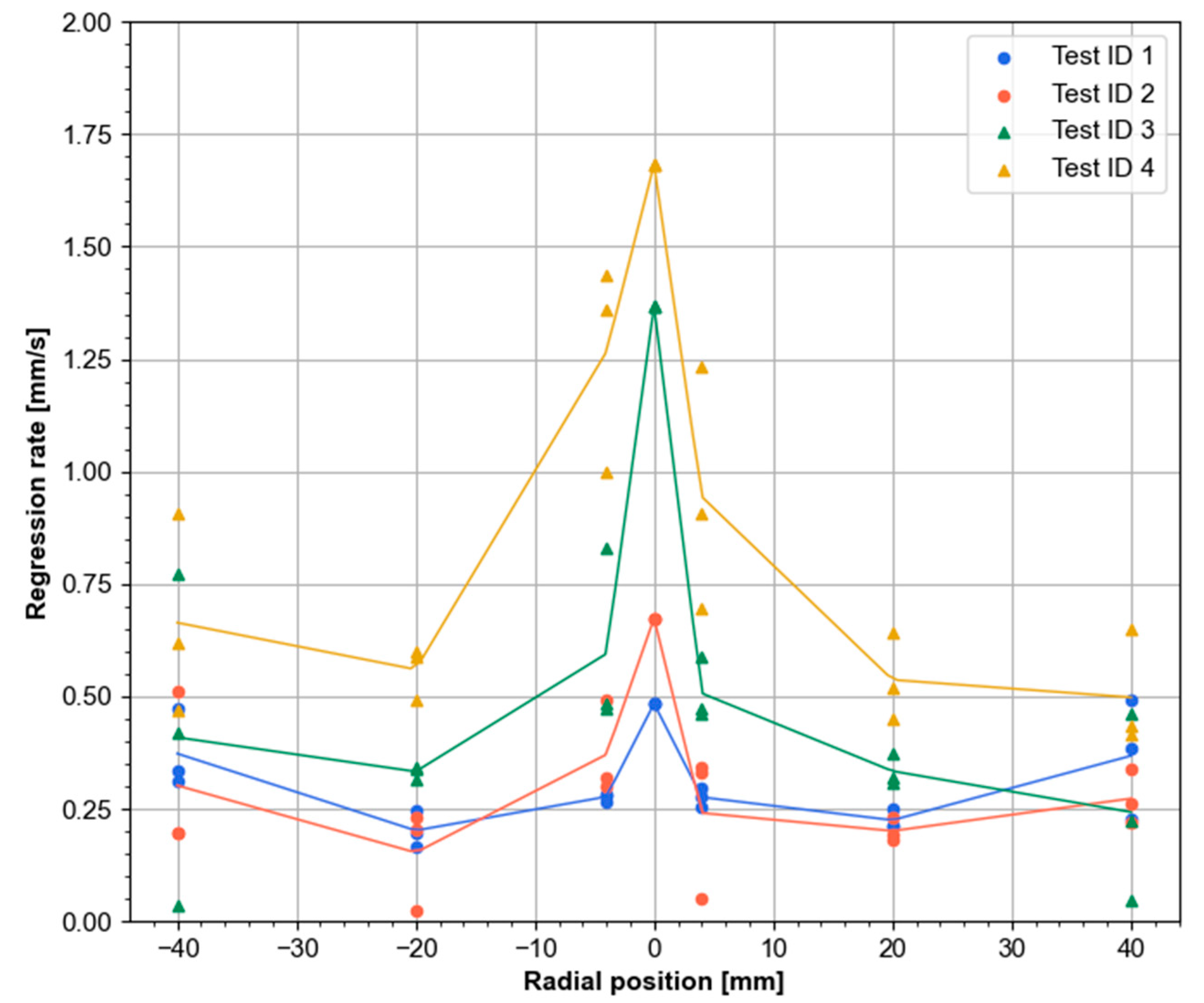
Post-test measurements were taken at various points on the top grain surface to estimate the local regression rate. Figure 14 presents the distribution of the regression rate along the radial direction for all tests. For each distance from the center, measurements were taken at several different angular positions. It can be observed that as the average regression rate increases, the non-uniformities in the regression rate become more pronounced. These findings are consistent with those reported by Rice et al. [10] or Lestrade et al. [7]. The regression rate appears to be highest within a small radius from the center, reaching approximately three times higher than the average, as well as at the grain’s edges. The central depression is particularly intriguing as it forms on a flat surface without the previous existence of any hollow. The impact of localized ignition using the torch igniter cannot be determined from the data obtained, but no significant non-uniformity resulting from such ignition was observed.
4. Conclusions
This paper reports the design and initial tests of the VFP hybrid rocket engine using self-pressurizing N2O and HDPE as propellants and a N2O/C3H8 torch igniter. To our knowledge, no previous attempts at operating a VFP hybrid with N2O and low-regression rate fuel have been reported in the literature.
The torch igniter tests were successful, demonstrating the feasibility of the concept while revealing potential issues that may affect repeatability and performance. The engine required a prolonged ignition time for successful ignition and achieving stable operating conditions. The collected data will aid in further refining the design for future testing.
The axial regression rate ballistic coefficients are reported for the N2O/HDPE propellants. The results of this research provide additional evidence concerning the non-uniform regression rate in both end-burning and VFP hybrids.
Author Contributions
Conceptualization, T.P.; methodology, T.P.; software, T.P.; formal analysis, T.P.; investigation, T.P.; resources, T.P.; writing, original draft preparation, T.P.; writing, review and editing, T.P. and J.C.; visualization, T.P.; supervision, J.C.; project administration, J.C.; funding acquisition, T.P. All authors have read and agreed to the published version of the manuscript.
Funding
This research was partially funded by the AGH University of Science and Technology.
Data Availability Statement
The data presented in this study are available upon request from the corresponding author.
Conflicts of Interest
The authors declare no conflict of interest.
References
- Anflo, K.; Crowe, B. In-space demonstration of an ADN-based propulsion system. In Proceedings of the 47th AIAA/ASME/SAE/ASEE Joint Propulsion Conference & Exhibit, San Diego, CA, USA, 31 July–3 August 2011; p. 5832. [Google Scholar] [CrossRef]
- Masse, R.; Allen, M.; Spores, R.; Driscoll, E.A. AF-M315E propulsion system advances and improvements. In Proceedings of the 52nd AIAA/SAE/ASEE Joint Propulsion Conference, Salt Lake City, UT, USA, 25–27 July 2016; pp. 1–10. [Google Scholar] [CrossRef]
- Whitmore, S.A. Nytrox as “Drop-in” replacement for gaseous oxygen in smallsat hybrid propulsion systems. Aerospace 2020, 7, 43. [Google Scholar] [CrossRef]
- Pokrupa, N.; Anflo, K.; Svensson, O. Spacecraft system level design with regards to incorporation of a new green propulsion system. In Proceedings of the 47th AIAA/ASME/SAE/ASEE Joint Propulsion Conference & Exhibit, San Diego, CA, USA, 31 July–3 August 2011; p. 6129. [Google Scholar] [CrossRef]
- Karabeyoglu, A.; Stevens, J.; Geyzel, D.; Cantwell, B.; Micheletti, D. High Performance Hybrid Upper Stage Motor. In Proceedings of the 47th AIAA/ASME/SAE/ASEE Joint Propulsion Conference & Exhibit, San Diego, CA, USA, 31 July–3 August 2011. American Institute of Aeronautics and Astronautics. [Google Scholar] [CrossRef]
- Kamps, L.; Hirai, S.; Nagata, H. Hybrid Rockets as Post-Boost Stages and Kick Motors. Aerospace 2021, 8, 253. [Google Scholar] [CrossRef]
- Lestrade, J.Y.; Anthoine, J.; Musker, A.J.; Lecossais, A. Experimental demonstration of an end-burning swirling flow hybrid rocket engine. Aerosp. Sci. Technol. 2019, 92, 1–8. [Google Scholar] [CrossRef]
- Jens, E.T.; Karp, A.C.; Nakazono, B.; Eldred, D.; Devost, M.; Vaughan, D. Design of a Hybrid CubeSat Orbit Insertion Motor. In Proceedings of the 52nd AIAA/SAE/ASEE Joint Propulsion Conference, Salt Lake City, UT, USA, 25–27 July 2016; pp. 1–19. [Google Scholar] [CrossRef]
- Martin, F.; Chapelle, A.; Lemaire, F. Promising Space Transportation Applications Using Hybrid Propulsion. In Proceedings of the 4th European Conference for Aerospace Sciences (EUCASS), Saint Petersburg, Russia, 4–8 July 2011; pp. 25–28. [Google Scholar]
- Rice, E.E.; Gramer, D.J.; St. Clair, C.P.; Chiaverini, M.J. MARS ISRU CO/O2 Rocket Engine Development and Testing. In Proceedings of the Seventh International Workshop on Microgravity Combustion and Chemically Reacting Systems, Cleveland, OH, USA, 3–6 June 2003; Available online: http://ntrs.nasa.gov/search.jsp?R=20040053504 (accessed on 1 August 2023).
- Casalino, L.; Masseni, F.; Pastrone, D. Optimal Design of Electrically Fed Hybrid Mars Ascent Vehicle. Aerospace 2021, 8, 181. [Google Scholar] [CrossRef]
- Whitmore, S.A.; Merkley, S.L.; Spurrier, Z.S.; Walker, S.D. Development of a Power Efficient, Restartable, “Green” Propellant Thruster for Small Spacecraft and Satellites. In Proceedings of the 29th Conference on Small Satellites, Logan, UT, USA, 8–13 August 2015. [Google Scholar]
- Whitmore, S.A. Additively Manufactured Acrylonitrile-Butadiene-Styrene–Nitrous-Oxide Hybrid Rocket Motor with Electrostatic Igniter. J. Propuls. Power 2015, 31, 1217–1220. [Google Scholar] [CrossRef]
- Jens, E.T.; Karp, A.C.; Rabinovitch, J.; Nakazono, B.; Conte, A.; Vaughan, D.A. Design of interplanetary hybrid cubesat and smallsat propulsion systems. In Proceedings of the 2018 Joint Propulsion Conference, Cincinnati, OH, USA, 9–11 July 2018; pp. 1–18. [Google Scholar] [CrossRef]
- Jens, E.T.; Karp, A.C.; Wiliams, K.; Nakazono, B.; Rabinovitch, J.; Dyrda, D.; Mechentel, F. Low pressure ignition testing of a hybrid smallsat motor. In Proceedings of the AIAA Propulsion and Energy 2019 Forum, Indianapolis, IN, USA, 19–22 August 2019. [Google Scholar] [CrossRef]
- Simurda, L.; Zilliac, G. Continued testing of a high performance hybrid propulsion system for small satellites. In Proceedings of the 51st AIAA/SAE/ASEE Joint Propulsion Conference, Orlando, FL, USA, 27–29 July 2015; pp. 1–23. [Google Scholar] [CrossRef]
- Gibbon, D.M.; Haag, G.S. Investigation of an Alternative Geometry Hybrid Rocket for Small Spacecraft Orbit Transfer; Spc 00-4036; Surrey Satellite Technology Ltd.: Guildford, UK, 2001; Volume 298. [Google Scholar]
- Hashish, A.; Paravan, C.; Visinoni, J. Effects of Vortex Flow Pancake Hybrid Rocket Engine Operating Parameters on Liquefying Fuel Combustion. In Proceedings of the AIAA AVIATION 2022 Forum, Chicago, IL, USA, 27 June–1 July 2022. [Google Scholar] [CrossRef]
- Hashish, A.; Paravan, C.; Verga, A. Liquefying Fuel Combustion in a Lab-scale Vortex Flow Pancake Hybrid Rocket Engine. In Proceedings of the AIAA Propulsion and Energy 2021 Forum, Virtual Event, 9–11 August 2021. [Google Scholar] [CrossRef]
- Hashish, A.; Paravan, C.; Scatton, C. Ballistic Characterization of Armored Grains with Vortex Flow Pancake Hybrid Rocket Engine. In Proceedings of the AIAA SCITECH 2023 Forum, National Harbor, MD, USA, 23–27 January 2023. [Google Scholar] [CrossRef]
- Hashish, A.; Paravan, C.; Guindani, M. Diagnostic Techniques for Regression Rate of Paraffin-Based Fuels in a VFP Hybrid Rocket Engine. In Proceedings of the AIAA SCITECH 2023 Forum, National Harbor, MD, USA, 23–27 January 2023. [Google Scholar] [CrossRef]
- Paravan, C.; Glowacki, J.; Carlotti, S.; Maggi, F.; Galfetti, L. Vortex combustion in a hybrid rocket motor. In Proceedings of the 52nd AIAA/SAE/ASEE Joint Propulsion Conference, Salt Lake City, UT, USA, 25–27 July 2016; pp. 1–21. [Google Scholar] [CrossRef]
- Paravan, C.; Piscaglia, F.; Galfetti, L. Influence of Operating Parameters on the Ballistics of a Lab-Scale Vortex Flow Pancake Hybrid Rocket Engine. In Proceedings of the 8th European Conference for Aerospace Sciences (EUCASS 2019), Madrid, Spain, 1–4 July 2019; pp. 1–9. [Google Scholar]
- Whitmore, S.A.; Bulcher, M.A. Vacuum test of a novel green-propellant thruster for small spacecraft. In Proceedings of the 53rd AIAA/SAE/ASEE Joint Propulsion Conference, Atlanta, GA, USA, 10–12 July 2017; pp. 1–18. [Google Scholar] [CrossRef]
- Dyrda, D.M.; Mechentel, F.S.; Cantwell, B.J.; Karp, A.C.; Rabinovitch, J.; Jens, E.T. Diode Laser Ignition of a Poly(Methyl Methacrylate) and Gaseous Oxygen Hybrid Motor. J. Propuls. Power 2020, 36, 773–782. [Google Scholar] [CrossRef]
- Padwal, M.B.; Castaneda, D.A.; Natan, B. Hypergolic combustion of boron based propellants. Proc. Combust. Inst. 2021, 38, 6703–6711. [Google Scholar] [CrossRef]
- Castaneda, D.A.; Natan, B. Hypergolic ignition of hydrogen peroxide with various solid fuels. Fuel 2022, 316, 123432. [Google Scholar] [CrossRef]
- Jobin, O.; Dumas, B.; Zahlawi, J.; Chartray-Pronovost, M.; Robert, É. Hypergolic ignition of paraffin-based hybrid rocket fuels by sprays of liquid oxidizer. Proc. Combust. Inst. 2022, 39, 5073–5082. [Google Scholar] [CrossRef]
- Conte, A.; Rabinovitch, J.; Jens, E.; Karp, A.C.; Nakazono, B.; Vaughan, D.A. Design, Modeling and Testing of a O2/CH4 Igniter for a Hybrid Rocket Motor. In Proceedings of the 2018 Fluid Dynamics Conference, Atlanta, GA, USA, 25–29 June 2018; pp. 1–14. [Google Scholar] [CrossRef]
- Okninski, A.; Surmacz, P.; Bartkowiak, B.; Mayer, T.; Sobczak, K.; Pakosz, M.; Kaniewski, D.; Matyszewski, J.; Rarata, G.; Wolanski, P. Development of Green Storable Hybrid Rocket Propulsion Technology Using 98% Hydrogen Peroxide as Oxidizer. Aerospace 2021, 8, 234. [Google Scholar] [CrossRef]
- Karabeyoglu, M.A. Nitrous Oxide and Oxygen Mixtures (Nytrox) as Oxidizers for Rocket Propulsion Applications. J. Propuls. Power 2014, 30, 696–706. [Google Scholar] [CrossRef]
- Industry Update: Prevalence of Nitrous-Based In-Space Propellants—Dawn Aerospace. Available online: https://www.dawnaerospace.com/latest-news/prevalence-of-nitrous-based-in-space-propellants (accessed on 29 July 2023).
- Sarritzu, A.; Felix, L.; Lukas, W.; Pasini, A. Assessment of Propulsion System Architectures for Green Propellants-based Orbital Stages. In Proceedings of the International Astronautical Congress: IAC Proceedings, Paris, France, 18–22 September 2022. [Google Scholar]
- Paravan, C.; Galfetti, L.; Bisin, R.; Piscaglia, F. Combustion Processes in Hybrid Rockets. Int. J. Energy Mater. Chem. Propuls. 2019, 18, 255–286. [Google Scholar] [CrossRef]
- Rice, E.E.; Chiaverini, M.J.; St. Clair, C.P.; Knuth, W.H.; Gustafson, R.J. Mars ISRU CO/O2 hybrid engine development status. In Proceedings of the 38th Aerospace Sciences Meeting and Exhibit, Reno, NV, USA, 10–13 January 2000. [Google Scholar] [CrossRef]
- Sakurai, T.; Oishige, Y.; Saito, K. Fuel regression behavior of swirling-injection end-burning hybrid rocket engine. J. Fluid Sci. Technol. 2019, 14, JFST0025. [Google Scholar] [CrossRef]
- Hirai, S.; Kamps, L.T.; Nagata, H. Development of safe, low-cost, re-ignitable rocket ignition system. In Proceedings of the AIAA Propulsion and Energy 2021 Forum, Virtual Event, 9–11 August 2021; AIAA Propulsion and Energy Forum. American Institute of Aeronautics and Astronautics, 2021. [Google Scholar]
- Razus, D. Nitrous Oxide: Oxidizer and Promoter of Hydrogen and Hydrocarbon Combustion. Ind. Eng. Chem. Res. 2022, 61, 11329–11346. [Google Scholar] [CrossRef]
- Zakirov, V.; Sweeting, M.; Goeman, V.; Lawrence, T. Surrey Research on Nitrous Oxide Catalytic Decomposition for Space Applications. In Proceedings of the 14th AIAA/USU Conference on Small Satellites, Logan, UT, USA, 21–24 August 2000; pp. 1–9. [Google Scholar]
- Zakirov, V.; Sweeting, M.; Lawrence, T.; Sellers, J. Nitrous oxide as a rocket propellant. Acta Astronaut. 2001, 48, 353–362. [Google Scholar] [CrossRef]
- Karabeyoglu, A.; Dyer, J.; Stevens, J.; Cantwell, B. Modeling of N2O decomposition events. In Proceedings of the 44th AIAA/ASME/SAE/ASEE Joint Propulsion Conference & Exhibit, Hartford, CT, USA, 21–23 July 2008; p. 4933. [Google Scholar]
- Balasubramanyam, M.; Moser, M.; Sharp, D. Catalytic Ignition of Nitrous Oxide with Propane/Propylene Mixtures for Rocket Motors. In Proceedings of the 41st AIAA/ASME/SAE/ASEE Joint Propulsion Conference & Exhibit, Tucson, AZ, USA, 10–13 July 2005; American Institute of Aeronautics and Astronautics: Tucson, AZ, USA, 2005. [Google Scholar]
- Smith, N.; Moser, M.; Kopicz, C., Jr.; Herdy, R. Nitrous oxide/propane rocket test results. In Proceedings of the 36th AIAA/ASME/SAE/ASEE Joint Propulsion Conference and Exhibit, Las Vegas, NV, USA, 24–28 July 2000. [Google Scholar]
- Herdy, R. Nitrous oxide/hydrocarbon fuel advanced chemical propulsion: Darpa Contract overview. In Proceedings of the 17th Annual Thermal Fluids Anal, Workshop, August 2006. [Google Scholar]
- Lohner, K.; Dyer, J.; Doran, E.; Dunn, Z.; Zilliac, G. Fuel regression rate characterization using a laboratory scale nitrous oxide hybrid propulsion system. In Proceedings of the 42nd AIAA/ASME/SAE/ASEE Joint Propulsion Conference & Exhibit, Sacramento, CA, USA, 9–12 July 2006; Volume 5, pp. 3494–3509. [Google Scholar] [CrossRef]
Figure 1.
Schematic view of different hybrids configuration: (a) conventional; (b) end-burning; (c) vortex flow pancake; (d) end-burning/vortex flow pancake horizontal cross-section at the injection plane. Fuel grains (orange blocks), oxidizer injection points (blue arrows), and combustion flow field (red arrows) are shown. The flow field is only shown schematically and does not directly represent actual flow lines. The cross-section in (d) highlights the tangential injection in EBH and VFP.
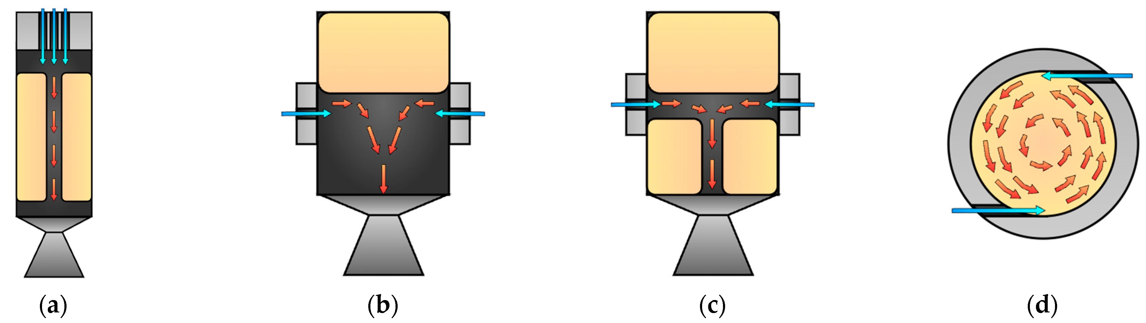
Figure 2.
VFP engine design: (a) vertical cross-section; (b) horizontal cross-section at the injection plane.
Figure 2.
VFP engine design: (a) vertical cross-section; (b) horizontal cross-section at the injection plane.
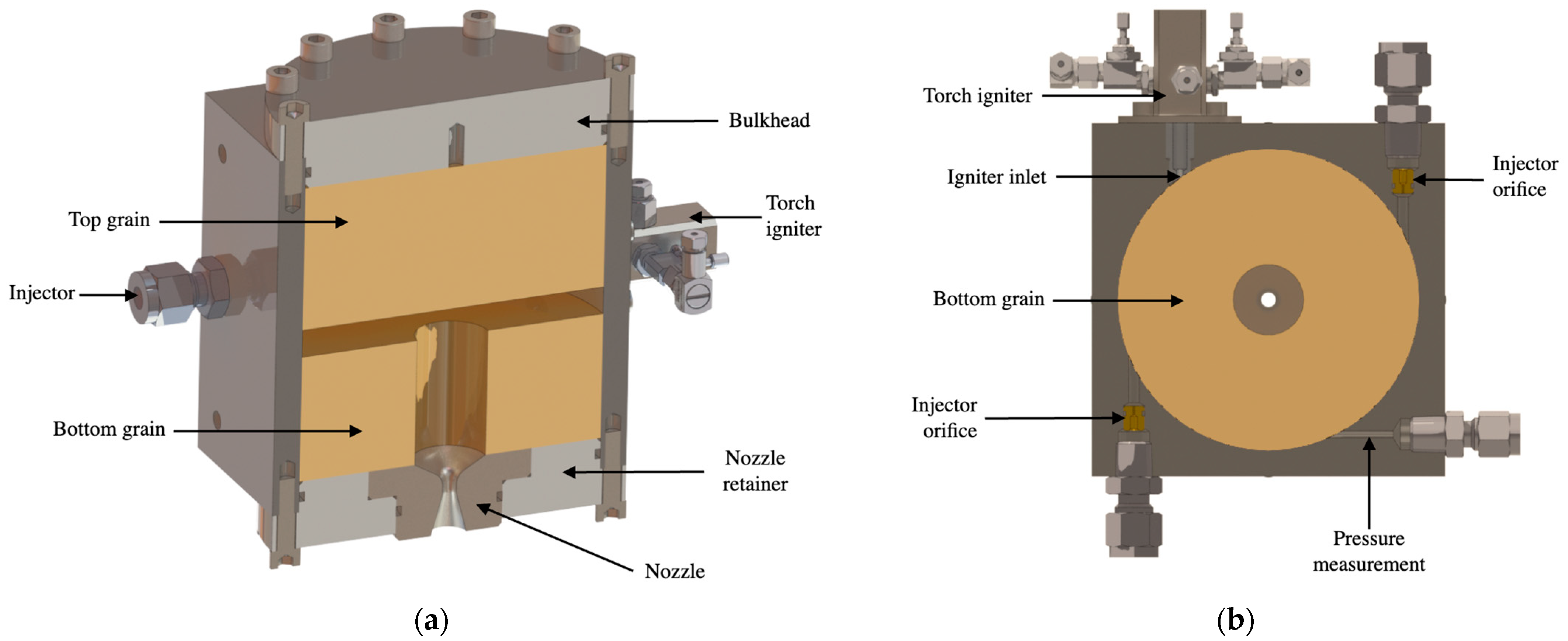
Figure 3.
Torch igniter design: (a) vertical cross-section; (b) horizontal cross-section at the injection plane.
Figure 3.
Torch igniter design: (a) vertical cross-section; (b) horizontal cross-section at the injection plane.
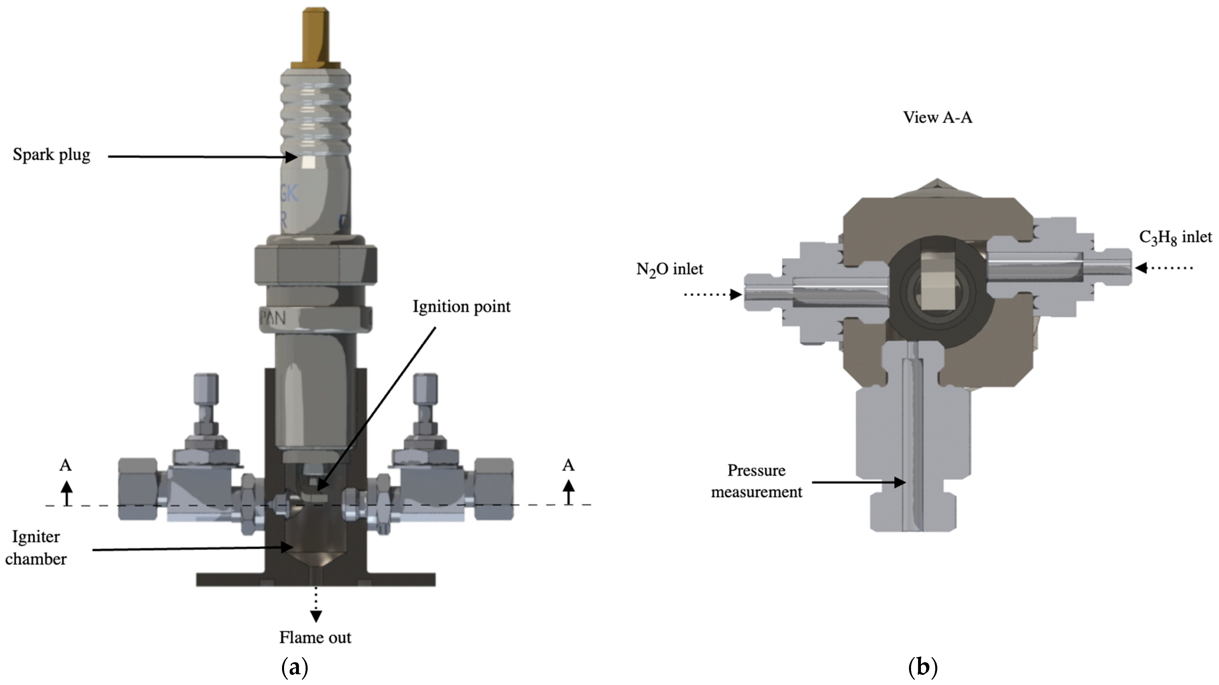
Figure 4.
Feedline and instrumentation overview diagram for the VFP test facility.
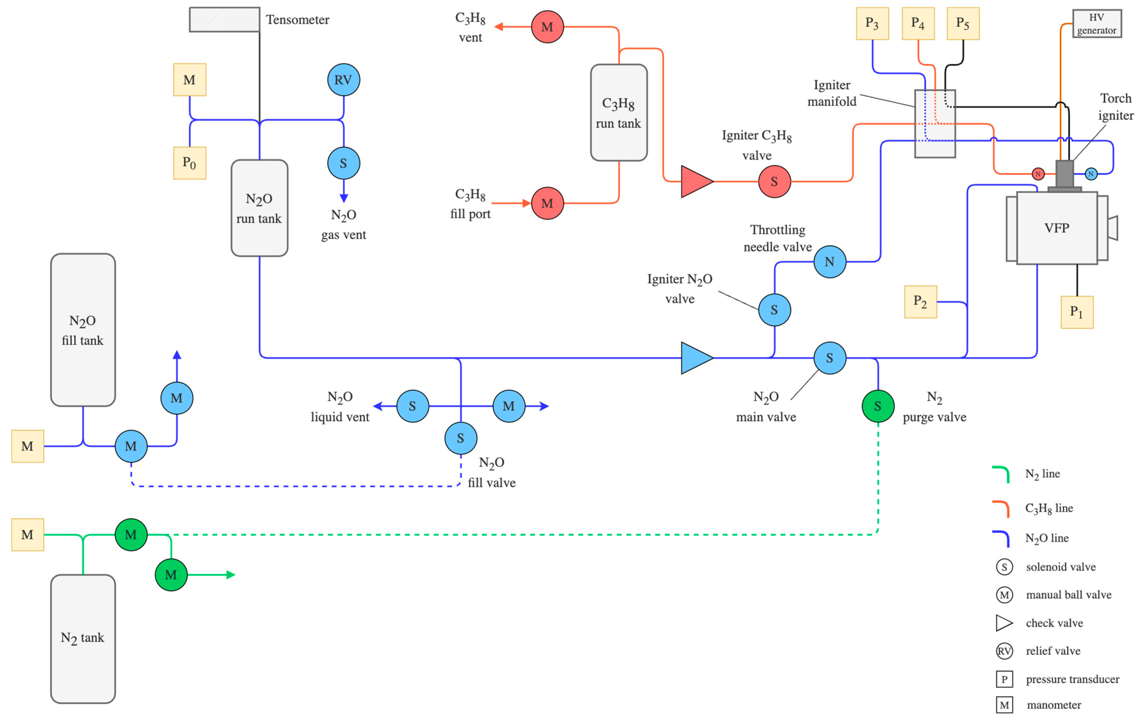
Figure 5.
VFP test facility setup ready for the hot-fire testing.

Figure 6.
Pressure and mass flow rate time history for the typical torch ignitor test using liquid N2O.
Figure 6.
Pressure and mass flow rate time history for the typical torch ignitor test using liquid N2O.
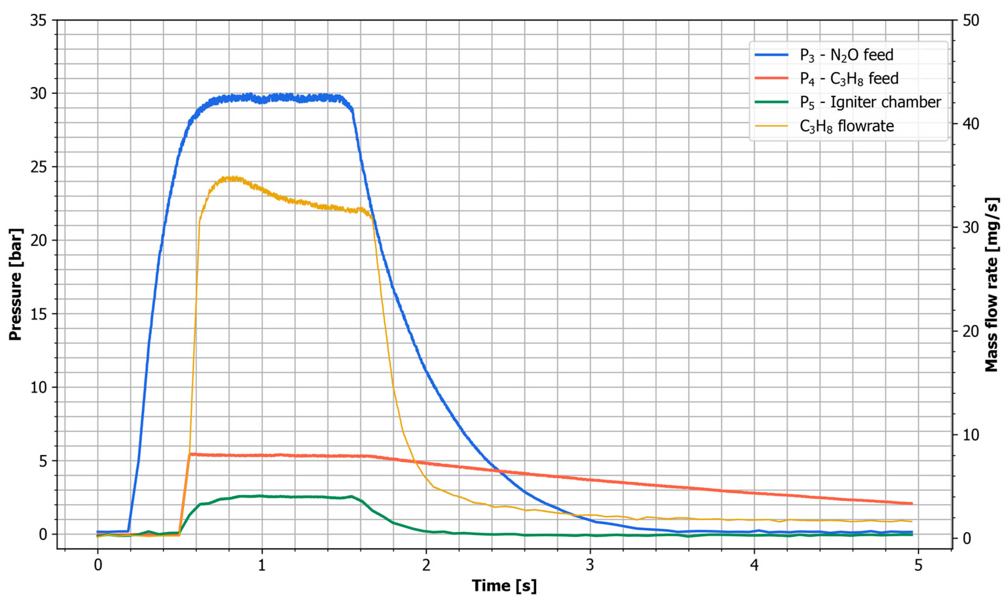
Figure 7.
Torch igniter during testing.
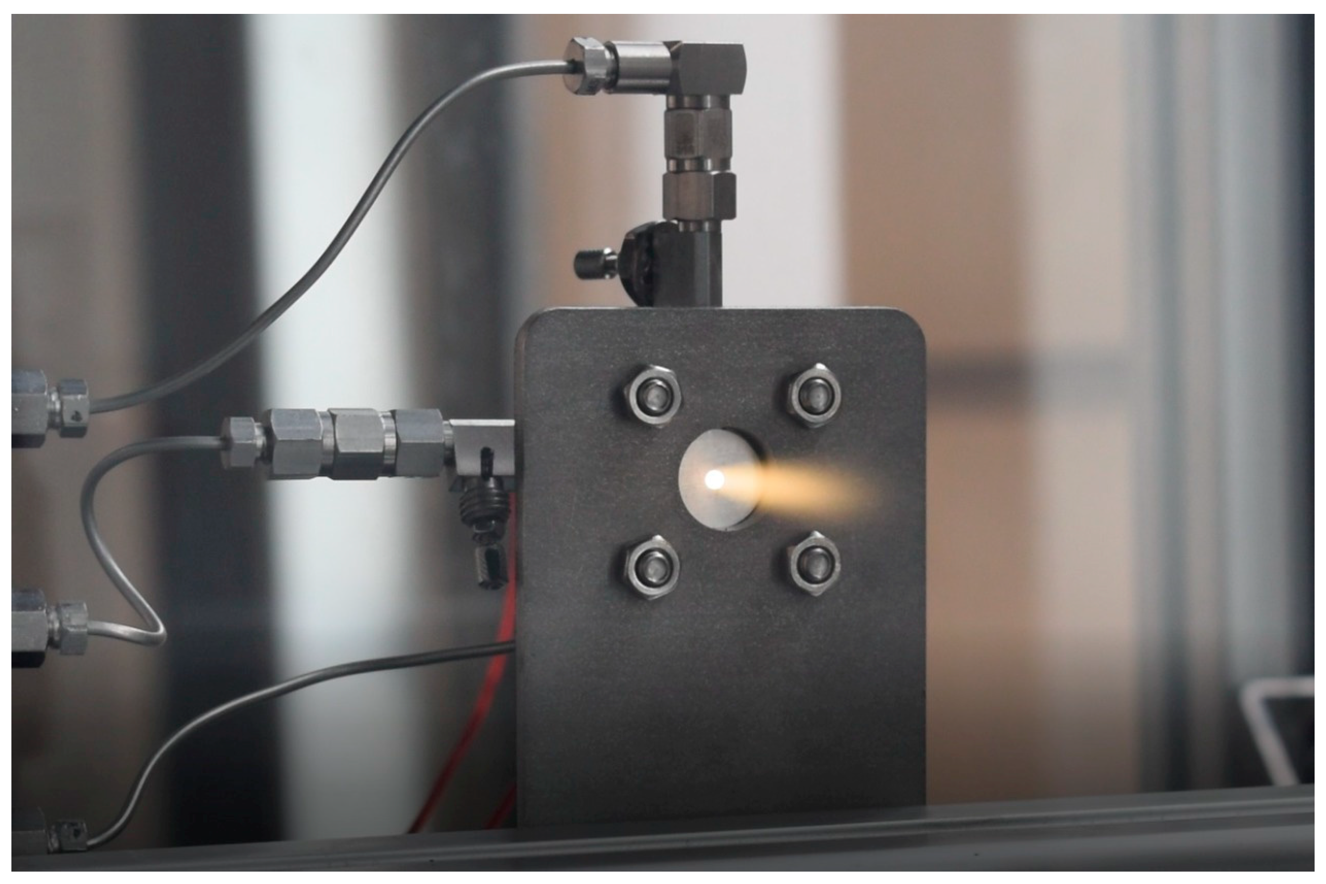
Figure 8.
N2O upstream injector pressure history for different ignitor tests using liquid and gaseous phase for the same initial tank conditions.
Figure 8.
N2O upstream injector pressure history for different ignitor tests using liquid and gaseous phase for the same initial tank conditions.
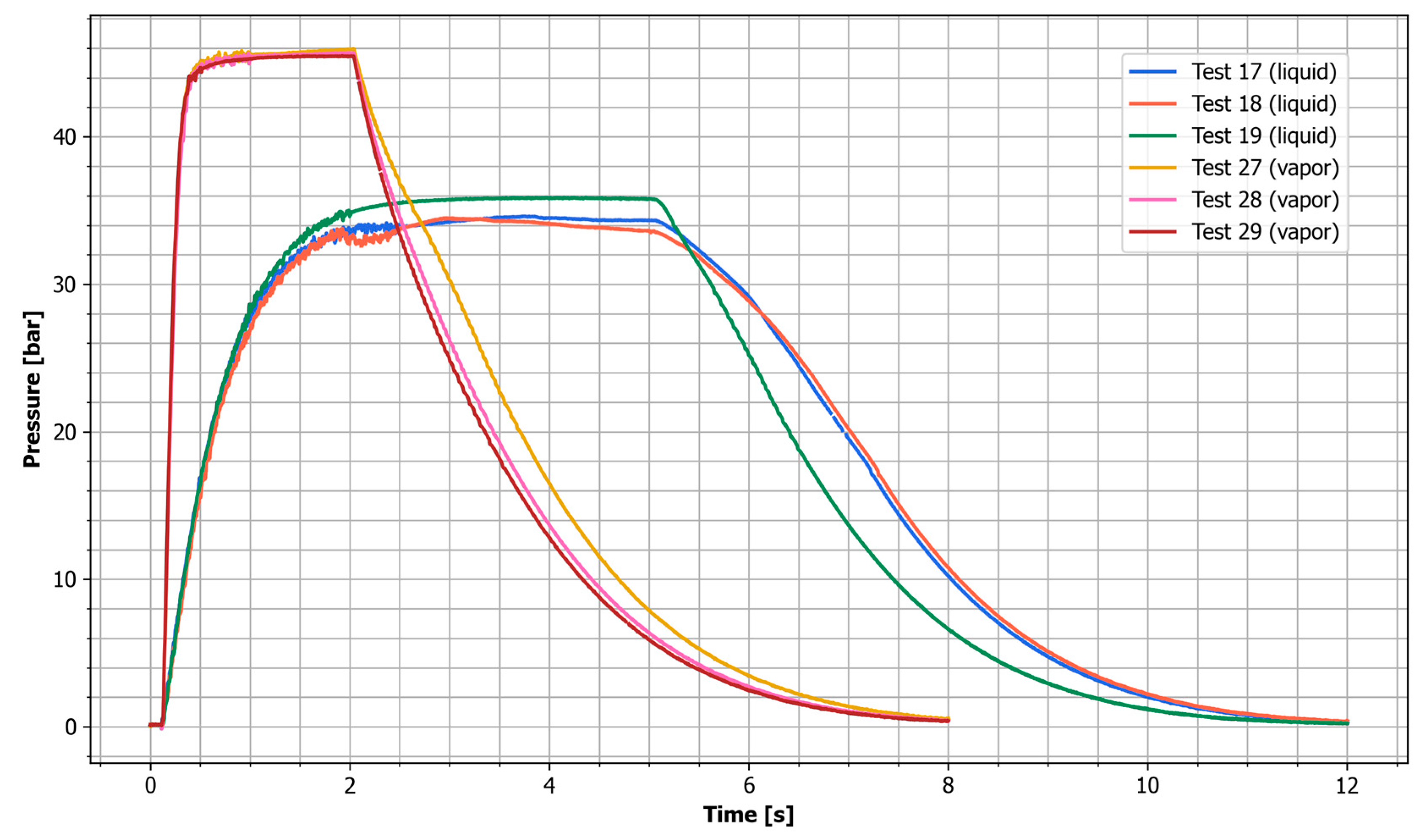
Figure 9.
Pressure and tank mass time history for the VFP engine Test 7.
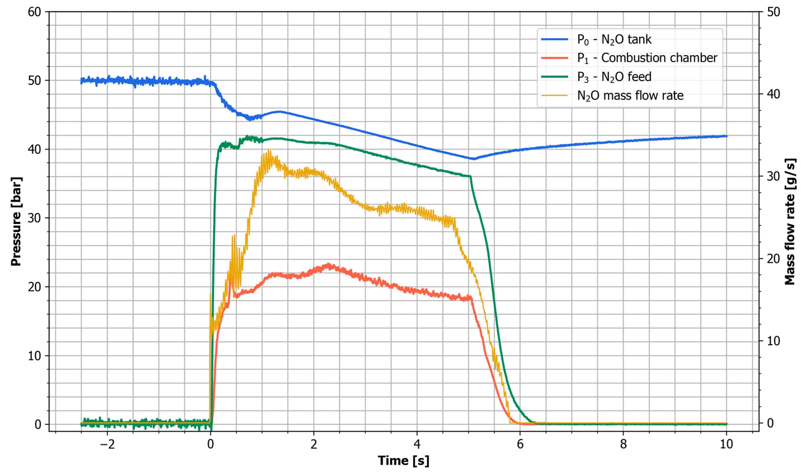
Figure 10.
Photo of the VFP hybrid rocket engine during the hot-fire test (Test 4).
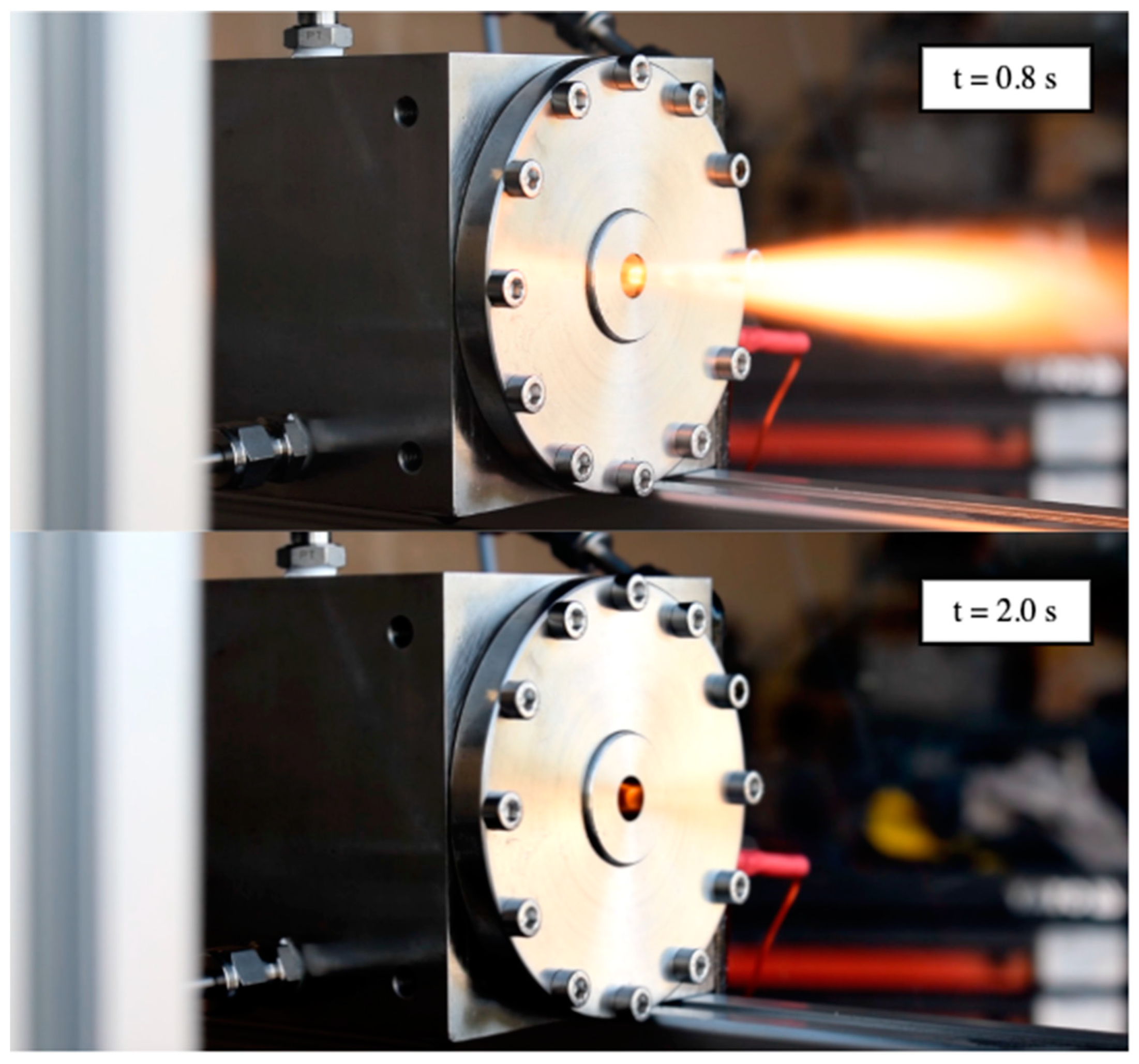
Figure 11.
Comparison of the Test 3 and Test 7 pressure traces.
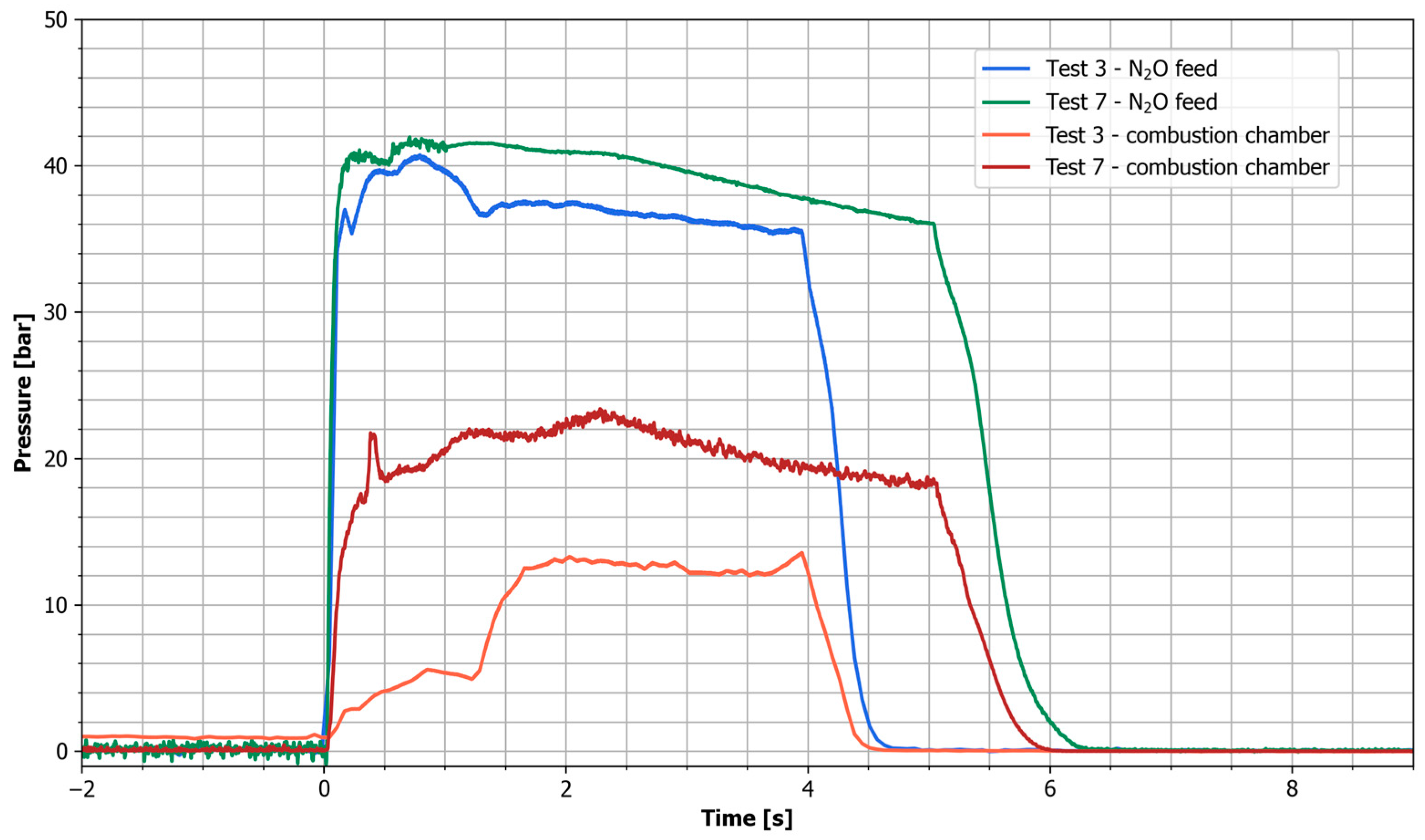
Figure 12.
Fuel grains after successful burn showing the vortex pattern on their surfaces. Test 1 (up), Test 3 (bottom).
Figure 12.
Fuel grains after successful burn showing the vortex pattern on their surfaces. Test 1 (up), Test 3 (bottom).

Figure 13.
Axial regression rate data for the N2O/HDPE propellants in the VFP hybrid.

Figure 14.
Radial regression rate distribution for the VFP hybrid Test 1–4.

Table 1.
Storable oxidizers for space propulsion with properties.
| Oxidizer | Chemical Composition [-] | Oxygen Content [%] | Storage Density a [kg/m3] | Vapor Pressure [Pa] | Freezing Temperature [K] |
|---|---|---|---|---|---|
| Gaseous Oxygen | O2 | 100 | 128.36 | 20 × 106 b | 54.36 |
| Nitrous Oxide | N2O | 36 | 786 c | 5.2 × 10⁶ | 182.3 |
| Hydrogen Peroxide d | H2O2 | 46 | 1431 | 133 | 272.72 |
a At 294 K. b Pressure to achieve reasonable storage density. c Liquid. d HTP 98 wt.%.
Table 2.
Design and operating parameters of the VFP engine.
| Parameter | Value | Unit |
|---|---|---|
| Propellants | N2O/HPDE | - |
| Combustion chamber diameter | 85 | mm |
| Initial fuel grain length | 40 (top) 35 (bottom) | mm |
| Bottom fuel port diameter | 20 | mm |
| Initial combustion chamber length | 10 | mm |
| Nozzle throat diameter | 4/6/6.4 | mm |
| Injector orifice | 0.5/0.8/1.2 | mm |
| Number of injectors | 2 | - |
Table 3.
Results of the torch igniter tests using liquid N2O.
| Test No | * | - | ||||
|---|---|---|---|---|---|---|
| 1 | 2.77 | 35.37 | 31.49 | 32.54 | 411.25 | 12.64 |
| 2 | 2.40 | 34.19 | 30.5 | 32.95 | 406.78 | 12.35 |
| 3 | 2.35 | 32.49 | 29.5 | 32.50 | 399.85 | 12.30 |
| 4 | 1.89 | 31.20 | 27.8 | 31.15 | 390.61 | 12.54 |
| 5 | 2.67 | 36.34 | 32.75 | 32.00 | 420.87 | 13.15 |
| 6 | 3.00 | 36.00 | 32.89 | 32.10 | 419.54 | 13.07 |
| 7 | 2.73 | 35.30 | 31.72 | 32.00 | 413.18 | 12.91 |
| 8 | 2.50 | 33.45 | 30 | 32.00 | 411.25 | 12.58 |
| 9 | - | - | - | - | - | - |
| 10 | 3.00 | 37.76 | 33.64 | 31.22 | 424.77 | 13.61 |
| 11 | 3.20 | 37.00 | 33.60 | 31.20 | 423.10 | 13.56 |
| 12 | 3.15 | 37.00 | 33.50 | 31.40 | 422.76 | 13.46 |
| 13 | 2.80 | 36.20 | 32.50 | 31.34 | 418.21 | 13.34 |
| 14 | 2.70 | 35.54 | 31.53 | 32.00 | 412.03 | 12.88 |
| 15 | 2.40 | 33.6 | 30.30 | 32.00 | 405.33 | 12.67 |
* estimated.
Table 4.
Results of the torch igniter tests using liquid N2O.
| Test No | N2O Phase | Result | ||
|---|---|---|---|---|
| 16 | Liquid | 5000 | 2500 | OK |
| 17 | 5000 | 2500 | OK | |
| 18 | 5000 | 2500 | OK | |
| 19 | 5000 | 2000 | OK | |
| 20 | 5000 | 2000 | OK | |
| 21 | 5000 | 1500 | Flame-out | |
| 22 | 5000 | 1500 | OK | |
| 23 | 2000 | 2000 | OK | |
| 24 | 2000 | 2000 | OK | |
| 25 | 2000 | 500 | No ignition | |
| 26 | 2000 | 500 | No ignition | |
| 27 | Vapor | 2000 | 1000 | OK |
| 28 | 2000 | 1000 | OK | |
| 29 | 2000 | 500 | OK | |
| 30 | 2000 | 350 | OK | |
| 31 | 2000 | 350 | OK |
Table 5.
Hot-fire test results for the VFP hybrid.
| Test No | - | ||||||||||||
|---|---|---|---|---|---|---|---|---|---|---|---|---|---|
| 1 | 4.0 | 0.5 | 3.0 | 4.96 | 6.7 | 6.8 | 1.22 | 0.25 | 0.09 | 2.72 | 4.03 | 1.48 | 6.71 |
| 2 | 4.0 | 0.5 | 3.0 | 5.66 | 7.0 | 6.9 | 1.83 | 0.23 | 0.08 | 2.45 | 6.07 | 2.48 | 8.54 |
| 3 | 6.0 | 0.8 | 3.0 | 4.27 | 7.3 | 8.2 | 4.20 | 0.31 | 0.16 | 3.62 | 13.93 | 3.84 | 9.32 |
| 4 | 6.0 | 0.8 | 3.0 | 4.27 | 12.6 | 15 | 3.84 | 0.54 | 0.48 | 6.45 | 12.72 | 1.97 | 12.71 |
| 5 | 6.4 | 1.2 | 10.0 | 5.2 | 23.3 | 28.5 | 7.67 | 0.86 | 0.72 | 10.36 | 26.45 | 2.55 | 20.17 |
| 6 | 6.4 | 1.2 | 10.0 | 5.2 | 22.8 | 28.2 | 7.79 | 0.84 | 0.72 | 10.20 | 26.86 | 2.64 | 20.07 |
| 7 | 6.4 | 1.2 | 10.0 | 5.2 | 22.5 | 28 | 7.62 | 0.83 | 0.71 | 10.10 | 26.26 | 2.60 | 19.71 |
| 8 | 6.4 | 1.2 | 10.0 | 2.2 | 10.7 | 13 | 7.14 | 0.98 | 0.82 | 11.85 | 26.05 | 2.20 | 18.18 |
| 9 | 6.4 | 1.2 | 10.0 | 2.2 | 11.4 | 14 | 7.27 | 1.05 | 0.88 | 12.70 | 26.50 | 2.09 | 19.44 |
| 10 | 6.4 | 1.2 | 10.0 | 2.2 | 11.3 | 14.6 | 6.50 | 1.04 | 0.92 | 12.95 | 23.70 | 1.83 | 20.08 |
| 11 | 6.4 | 1.2 | 10.0 | 5.1 | 27.9 | 32.8 | 7.03 | 1.00 | 0.94 | 11.90 | 23.29 | 1.96 | 19.6 |
Disclaimer/Publisher’s Note: The statements, opinions and data contained in all publications are solely those of the individual author(s) and contributor(s) and not of MDPI and/or the editor(s). MDPI and/or the editor(s) disclaim responsibility for any injury to people or property resulting from any ideas, methods, instructions or products referred to in the content. |
© 2023 by the authors. Licensee MDPI, Basel, Switzerland. This article is an open access article distributed under the terms and conditions of the Creative Commons Attribution (CC BY) license (https://creativecommons.org/licenses/by/4.0/).
Share and Cite
MDPI and ACS Style
Palacz, T.; Cieślik, J. Testing of the N2O/HDPE Vortex Flow Pancake Hybrid Rocket Engine with Augmented Spark Igniter. Aerospace 2023, 10, 727. https://doi.org/10.3390/aerospace10080727
AMA Style
Palacz T, Cieślik J. Testing of the N2O/HDPE Vortex Flow Pancake Hybrid Rocket Engine with Augmented Spark Igniter. Aerospace. 2023; 10(8):727. https://doi.org/10.3390/aerospace10080727
Chicago/Turabian StylePalacz, Tomasz, and Jacek Cieślik. 2023. "Testing of the N2O/HDPE Vortex Flow Pancake Hybrid Rocket Engine with Augmented Spark Igniter" Aerospace 10, no. 8: 727. https://doi.org/10.3390/aerospace10080727
Note that from the first issue of 2016, this journal uses article numbers instead of page numbers. See further details here.