Computational Analysis of 3D Lattice Structures for Skin in Real-Scale Camber Morphing Aircraft

1
Department of Mechanical and Manufacturing Engineering, Tennessee State University, Nashville, TN 37209, USA
2
KBJ Innovation Co., Nashville, TN 37218, USA
*
Author to whom correspondence should be addressed.
Aerospace 2019, 6(7), 79; https://doi.org/10.3390/aerospace6070079
Submission received: 26 April 2019
/
Revised: 3 June 2019
/
Accepted: 15 June 2019
/
Published: 7 July 2019
(This article belongs to the Special Issue Adaptive/Smart Structures and Multifunctional Materials in Aerospace)
Abstract
:Conventional or fixed wings require a certain thickness of skin material selection that guarantees structurally reliable strength under expected aerodynamic loadings. However, skin structures of morphing wings need to be flexible as well as stiff enough to deal with multi-axial structural stresses from changed geometry and the coupled aerodynamic loadings. Many works in the design of skin structures for morphing wings take the approach either of only geometric compliance or a simplified model that does not fully represent 3D real-scale wing models. Thus, the main theme of this study is (1) to numerically identify the multi-axial stress, strain, and deformation of skin in a camber morphing wing aircraft under both structure and aerodynamic loadings, and then (2) to show the effectiveness of a direct approach that uses 3D lattice structures for skin. Various lattice structures and their direct 3D wing models have been numerically analyzed for advanced skin design.

1. Introduction
Wing morphing is a concept whereby the shape of an aircraft’s wing is altered in a continuous manner to suit the desired flight condition. This change can occur in many ways: sweep angle, chord length, span length, and airfoil [1,2,3], as shown in Figure 1. Wing morphing aims to minimize fuel consumption by reducing drag forces in corresponding flight modes [4]. Recently, many researchers have worked towards the study of using smart materials and their aerodynamic reactions to investigate and realize shape morphing [5,6]. Among morphing types, camber changes in airfoil morphing have been widely studied by many researchers [7,8,9,10] due to their effective and simple implementation and control.
However, the importance of skin material/structure in morphing wings has been neglected due to its complexity. Conventional or fixed wing aircrafts use a 1–2 mm thick aluminum skin that is wrapped and stiff enough to endure aerodynamic effects. The skin structure is expected to deform in a 1–2 mm out-of-plane direction under maximum aerodynamic loadings. In the case of morphing wings, not only newly induced structural stress to the wing but the associated aerodynamic effects caused by shape changes should be also considered. For example, in chord extension morphing, the skin around the wing is not only required to be flexible in the chord direction but also to maintain out-of-plane or span directional loadings, which makes compliant skin design challenging.
Many works in the design of skins for morphing wings, which often use smart materials, consider only geometric or static deformations but not dynamic ones [11,12]. Kuder et al. [13] made an extensive survey into skin morphing structures and showed that an interdisciplinary approach is required through analysis to bring morphing technology into maturity, although most of the references reviewed in the paper focus on either in-plane structural stress-relevant skin design only or find an equivalent material satisfying in-plane structural stress. Similarly, La et al. [14] made another comprehensive survey of flexible skins that use composite lattice materials. Composite skin is one of techniques which are expected to overcome this challenge [15,16,17,18] through the advancement of material aspects. Recently, lattice structures for morphing wing skin have gained enormous attention as a result of their material compliancy in cellular structures. Single and double-wall corrugated structures [19,20,21,22,23] were studied to improve structural strength as well as to sustain aerodynamic loads. Also, adding hierarchical sub-structures to these walls implied [24,25] an increase of the material’s compliancy and a reduction of the required tension loads for skin morphing. In lattice design for skin, a chiral structure [26,27,28,29] has gained special attention due to its bending response compared to other structures. However, the chiral structure has shown poor flexibility in all other directions. Overall, the suggested lattice materials and structures for skin are also limited to 2D geometry only or do not fully address multi-axial morphing. In another series of works [30,31,32,33,34,35], the authors studied the properties of materials for skin such as their elastic modulus, shear modulus, relative density, and Poisson’s ratio for this structure, but these have not been realized into a model. Alsaidi et al. [36] also first analyzed the behavior of conventional skin under multi-dimensional morphing and then showed the anticipated stress, strain, and deformation in multi-axes for a skin structure design. However, this was also not materialized into a model for design. In the recent advancement of materials for compliant skin design, some researchers have suggested the use of carbon nanotubes [37], which have the potential to change electrical conductivity that responds to structural properties but not to sustain aerodynamic loads.
In summary, the goal of this study is to design a compliant skin structure for camber morphing wings. However, a simple geometry-structured material for skin in conventional aircraft is not compliant with multi-axial 3D morphing motions such as warping, twisting, and bending from camber morphing. Furthermore, most of the computational models are simplified ones that do not represent real-scale wings properly due to the multi-axial camber morphing motion. To overcome this design challenge, we here suggest a direct approach to perform the numerical analysis of 3D lattice structures for skin in full-scale camber morphing wing aircraft. Various 3D lattice structures directly wrapped around the wing under deformation from morphing have been analyzed for their stress, strain, and deformation in multi-axial dimensional structural and aerodynamic loadings. Through this analysis, we aim to clarify the effectiveness of a more practical 3D lattice model in a real-scale 3D camber morphing model under structural and aerodynamic loadings. This study will lead to the future development of a modified lattice structure to meet the required design criteria for real-scale 3D lattice structures for skin in camber morphing aircraft.
2. Aircraft Model and Actuation Mechanism
2.1. Aircraft Model
A retired UAV (Unmanned Aerial Vehicle) model, RQ-7, is selected for the wing base model shown in Figure 2. The dimensions of the wings are 1.828 m in span and 0.54 m in the chord direction. We now assume wings morph their camber rates up to 6% with a base airfoil NACA (National Advisory Committee for Aeronautics) 2410. For the skin design purpose, the skin requirement in a conventional fixed wing aircraft is 4.6 kg/m2 with an aluminum sheet that is stiff enough in the out-of-plane direction. The spar is located 40% from leading edge (i.e., 216 mm). These specifications are summarized in Table 1.
In our computational model of the wing, evenly spaced ribs as shown in Figure 2 are positioned and hollow in-between. Each rib can morph up to 6% to realize seamless and conformal camber morphing as expected.
2.2. Camber Morphing Wing Model
The model shown in Figure 3a consists of 6 actuators mechanism each of 40 mm width. The spar is the only fixed part in the model located 40% from the leading edge. All actuators are connected through the spar, which in turn is connected to an aircraft fuselage. The span is 1.828 m divided into 6 sections of 258.13 mm and a root rib of 40 mm. The reason for such division is to ensure the smooth morphing transition of the 6% camber rate (from NACA 2410 to NACA 8410). Each one of these actuators has the capability to deform to any range within 6%. In actual systems, linear DC motor actuators are positioned between the ribs, and, by adjusting the actuating power.
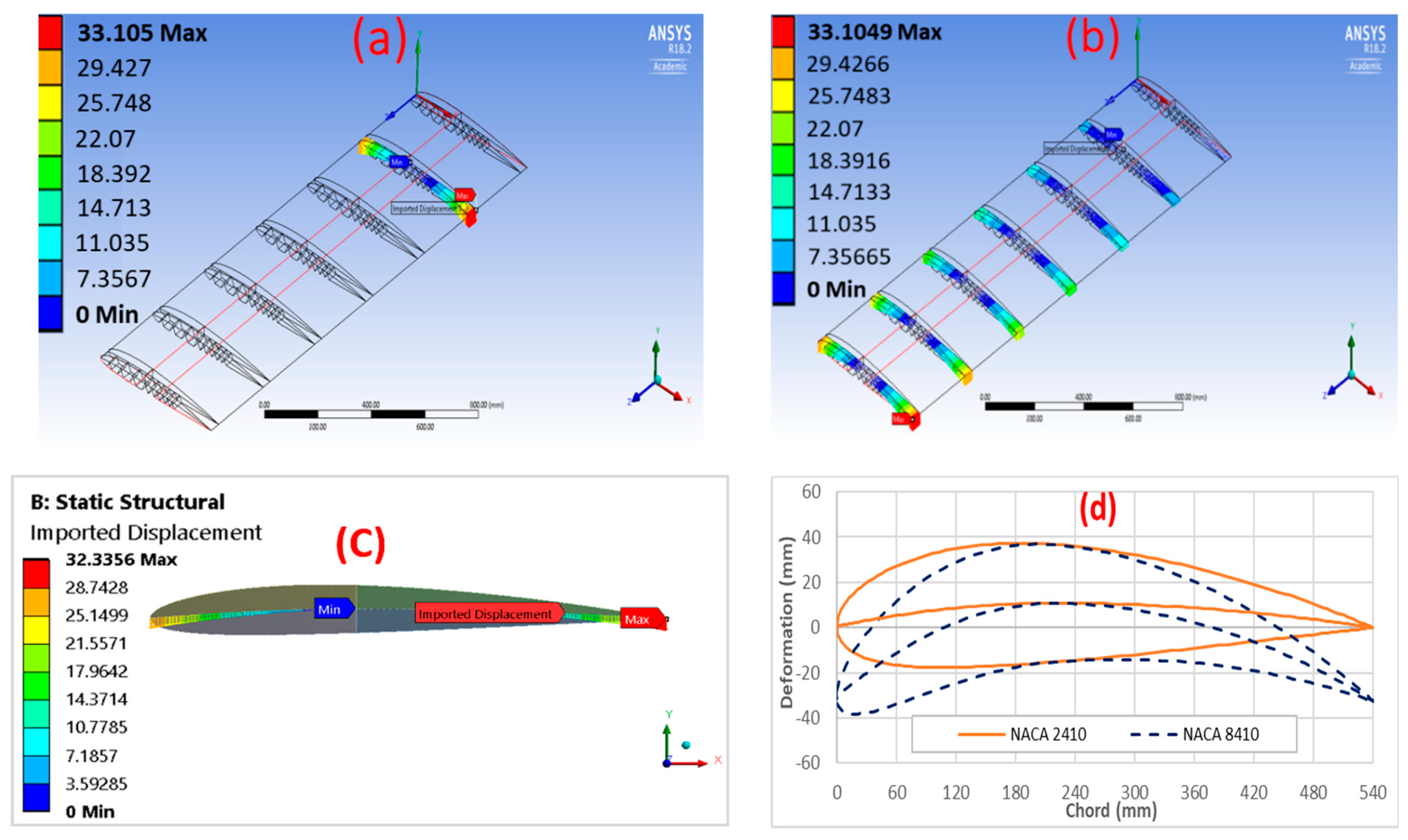
Two cases will be suggested in this study, which are linear and step morphing. In linear morphing, the camber of the model is capable of deforming to its maximum value (NACA8410 profile) at the free end while it remains undeformed (NACA2410) at the fixed side. The linearity of displacement is to ensure that the wing retains undeformed in the fixed side (NACA2410) while it achieves the maximum deformation (NACA8410) at the free side. In step morphing, only one actuator is set to deform to its maximum value of NACA 8410, while the others remain off at a NACA 2410 profile. The attained optimal NACA8410 chamber profile was found to be when we applied 30.6 mm in the bottom edge leading side and 32.3 mm in the bottom edge trailing side. A structural modeler by the software company ANSYS [39] is used in this study. The initial structure is created by forming a wing of the NACA 2410 profile, which means the wing is free of stresses. For computational simplicity, a section of two actuators are modeled, as shown in Figure 3b.
2.3. Camber Morphing Model
The original structure is created at first by forming a wing of the NACA 2410 profile. Then, the wing structure is wrapped with a 5 mm lattice layer. The material of the designed wing and skin layer are required to be flexible enough that it would comply with any deformation that would be undergone without fracture. An acrylonitrile butadiene styrene copolymer (ABS) composite is selected in this study. This material has significant properties that make it a great option, such as its high strength at low density, high flexibility in complying with the desired input of deformation, and a longer life compared to some other plastics. The spar is located 40% from leading edge and is the only fixed part of the wing.
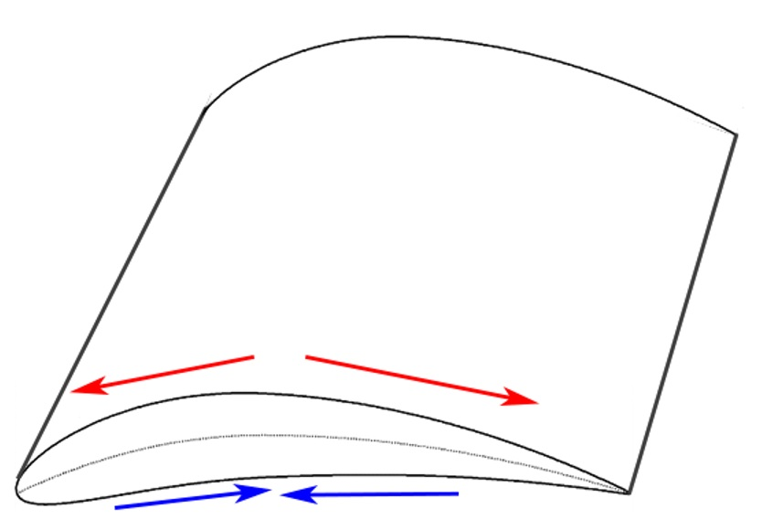
Two types of camber morphing are considered: (1) step morphing in Figure 4a, and (2) linear morphing in Figure 4b. For our computational model, the variable input displacement used to morph each actuator is based on the desired airfoil profile. Figure 4c shows the NACA 8410 input displacement profile. In step morphing, the model morphs up to 6%, while in linear morphing, there is only a 1% camber rate. The step morphing case is needed for structural analysis, while linear morphing is required for aerodynamic analysis. The most expected critical scenario for structural failure is when the skin deforms to its maximum airfoil profile, where the maximum stresses/strains may happen due to twisting and bending forces. Similarly, it is convenient to perform aerodynamic analysis in the linear morphing scenario since the skin will not be stretched at this case, and the maximum deformation may be captured. Figure 4d shows comparisons of 2D airfoil profiles of 1% and 6% camber rates; i.e., NACA2410 and NACA8410.
However, in general, the number of actuators depends on the size of the wing and the percentage of camber change. Thus, the challenge to achieve such a profile is due to the reaction of the internal structure of the wing against the applied displacement. The boundary conditions and their perspective coordinates for our model are tabulated in Table 2.
2.4. Skin Models
A two-layered skin model is used in this study. The internal layer consists of a lattice structure of 5 mm thickness. The internal layer is required to give the required structural support to the external layer. The external layer is 1 mm thick and placed on top of the first layer. The external layer is used to ensure surface continuity to improve aerodynamic performance. The material of both layers is assumed to be homogenous, with no-separation contacts between layers. The external skin is assumed to have a stiffness about 1/10th that of the internal skin to passively follow the internal structure. The external skin is a bulk material wrapped over a lattice structure, which is meant to give the required surface continuity for better aerodynamic performance. The nature of the morphed wing, which should not undergo any permanent deformation, is assumed to have linear elastic material properties. Both layers are assumed to be a shell structure model in solver at ANSYS, as shown in Figure 5a. The actuators were modeled using tetrahedron and hexahedron-type solid elements. A total of about 1.6 million elements are used to model the six actuators and skins (Figure 5b–d).
3. Lattice Structures for Skin
3.1. Selected Lattice Models
Five lattice structures were selected and studied: honeycomb, auxetic, chiral, zero-Poisson’s ratio honeycomb, and square lattices, as shown in Figure 6.
The deformational force applied to the wing by the actuators causes the wing to morph due to the structural flexibility of the lattice. The deformed compliant mechanism then causes the deformation of the wing boundary, which in turn changes the shape of the wing [40]. Figure 7 shows the selected lattice structures applied to real-scale 3D wing models. Using the same material—ABS—but different lattice structures enables the customization of parameters to meet desired structural behaviors. Three-dimensional lattice structures for computational analysis are wrapped in a sectional morphing wing (rib to rib) as shown in Figure 7. There are specific reasons for selecting these structures: (1) the previous history of studies into morphing wing skins; (2) a zero or low Poisson’s ratio; (3) low in-plane stiffness and high out-of-plane stiffness; and (4) sufficient flexibility for morphing performance. All structures are modeled with the same relative mass density of about 0.38. The overall relative density is kept the same for all structures by adjusting their parameters t, x, and l based on the formulas shown next to each skin type in Figure 6.
3.2. FE (Finite Element) Computational Verification
Variable stiffness materials refer to materials in which the mechanical properties change as a function of their spatial position. A lattice is a material that has such a characteristic. One of the advantages of variable stiffness materials during morphing is the adjustment capability of the system’s actuation energy. It enables the tailoring of the morphing profiles, i.e., the deformed shape of the morphing trailing edge, which significantly affects the aerodynamic and aeroacoustic performance of the airfoils [41]. Honeycomb structures have received significant attention due to their high isotropy in mechanical properties [42]; therefore, the zero Poisson’s ratio honeycomb introduced by Bubert [43] is the selected model for our verification process, which is shown in Figure 8.
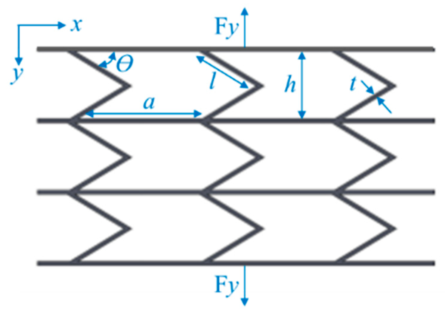
The structure is subjected to in-plane tensile or compressive force along the y-axis. For small deflection, the wall structure can be considered as an Euler–Bernoulli beam. The effective stiffness of the structure can be obtained by transforming the force–displacement relationship into a stress–strain relationship, which is by evaluation the global equivalent stress and strain of the structure. After derivation processes [43], the relative stiffness can be represented in the following form:
where is the Young’s modulus of the material. Equation (1) demonstrates that the relative stiffness of the honeycomb structure is independent of its structural depth and the amount of applied load. However, the analytical solution of this derivation has been verified and compared with the simulated model using the FEM analyzation as shown in Figure 9, where a good agreement has been observed.
3.3. Mesh Independence Study
Since we are dealing with computational model analysis in this study, it is important to evaluate the amount of error for the converged results. The obtained results related to mesh density are varied. Therefore, it is essential to examine these results such that the minimum running time can be identified with the least amount of error. However, the method for carrying out a mesh independence study is fairly straightforward. Thus, some of the mechanical properties of the base-skin model are evaluated for different sizes of mesh elements. The size of the model used is one segment of wing skin between two actuators; i.e., a 260 mm span by a 540 mm chord by 5 mm thick (Figure 3).
Maximum principal stress, equivalent stress, and maximum shear stress are evaluated for this model and the error calculated based on the following formula:
The error is found to be less than 5% for about 650,000 nodes, as shown in Figure 10. Therefore, the element size at this result, which is 2.5 mm, will be considered as the mesh density for all computational models in this study, where the solution is also independent of the mesh resolution.
3.4. Mechanical Properties and FE Model
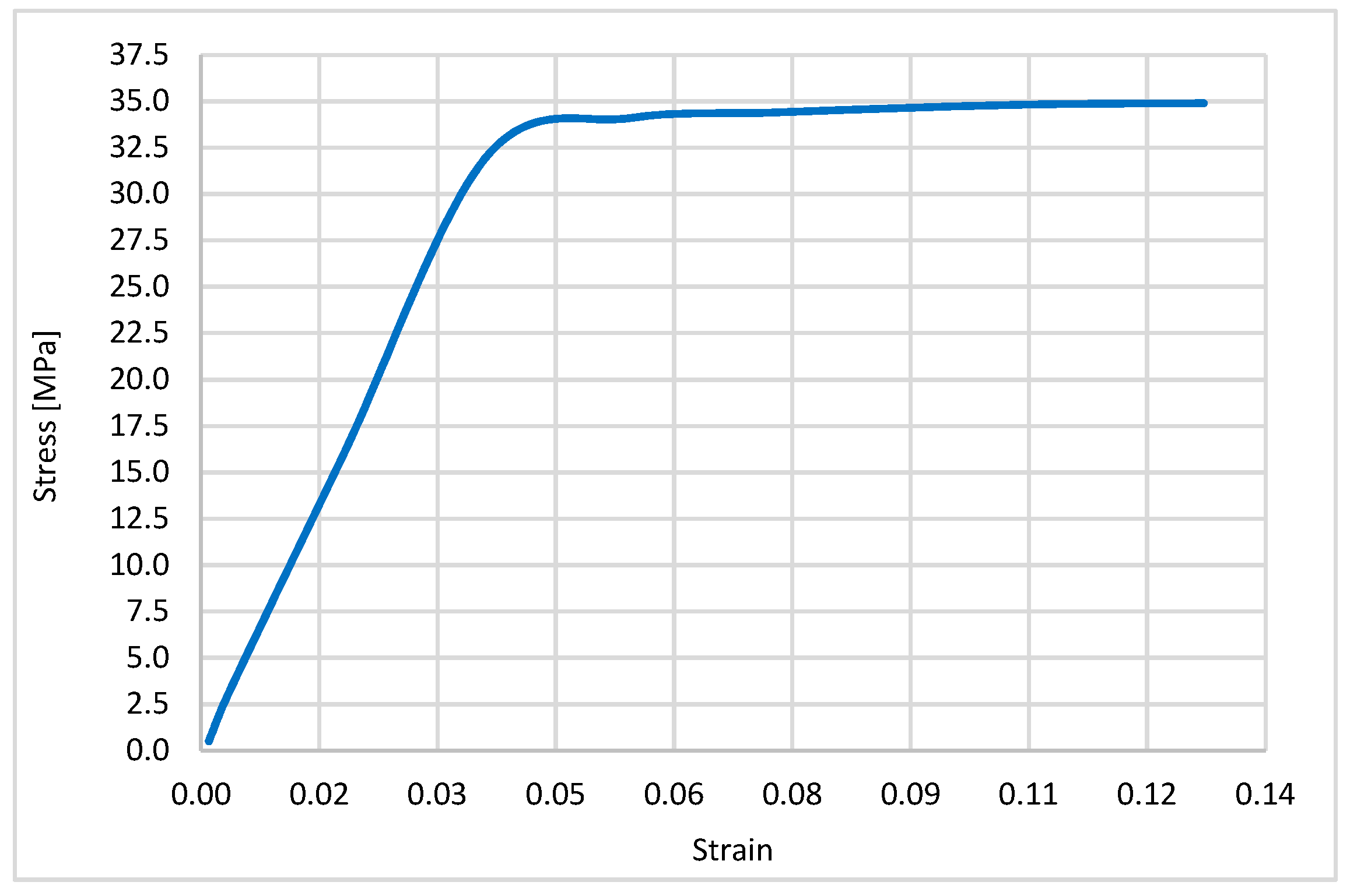
The finite element models were developed by hexahedron and tetrahedron-shaped elements in ANSYS [39]. The material properties of the lattice structure were assumed to be ABS Plus (acrylonitrile butadiene styrene copolymer), printable with a 3D printer. The bulk material properties of ABS Plus were obtained by a 3D-printed uniaxial dog-bone tensile specimen with an in-fill density and layer thickness of 0.33 mm. A tensile stress–strain curve of the bulk ABS Plus materials is shown in Figure 11. Material response is divided into elastic and plastic zones. The defined mechanical properties of ABS Plus was a Young’s modulus of 1.037 GPa, a Poisson’s ratio of 0.4, and a yield stress of 34.611 Mpa. The elastic behavior follows Hook’s law, and the plastic behavior was modeled by bilinear isotropic hardening plasticity in ANSYS.
4. Numerical Analysis
4.1. Structural Analysis
The deformation force applied to the lattice and external skin material by actuators causes them to morph. Figure 12 shows the color plot for some of the important material properties related to step morphing cases for each of the collected skins, while Table 3 represents their perspective values. In general, it is observed that a zero Poisson’s ratio honeycomb creates the minimum amount of equivalent stress when it morphs compared to other structures, while honeycomb develops the least amount of shear strain. These results clearly explore the poorness of these structures to respond to the required morphing since they all undergo excessive stresses which are way beyond the material’s allowable stress. However, these properties cannot be modified with conventional material, but it is possible to modify a lattice structure by making some structural modification. These structures naturally address the necessities of advanced internal skin to develop design criteria for skin behaviors.
From the achieved results in Table 3, the zero Poisson’s ratio honeycomb generated the lowest amount of equivalent stress. The chiral structure generated the lowest in-plane shear stress. The auxetic structure shows low normal stresses compared to other structures. However, all these selected lattice models failed to meet the yield strength limit of the ABS material.
4.2. Aerodynamic Analysis
Each of the lattice models are examined against a 5 g aerodynamic load. Based on the collected RQ-7 specifications, the empty weight is approximated to be around 823.8 N while the gross weight is about 1646.8 N. If it is assumed that the top surface of the wing carries 5 times the gross weight (i.e., a 5 g load) and the bottom surface carries once the gross weight (i.e., a 1 g load), then the pressures on the top and bottom surfaces would be 4171.93 Pa and 834.386 Pa, respectively. Figure 13 demonstrates the color plot results for this study while Table 4 tabulates the magnitudes of out-of-plane deformation for each model. Note that the external skin deforms the same amount as the internal structure since they are assumed to be in touch at all times (no-separation contacts).
From the achieved results, the square lattice experiences the lowest amount of deformation while the chiral structure deforms the largest in all directions. However, these experience significantly too much out-of-plane deformation. Therefore, these structures cannot be used as they are without geometrical modifications. These modifications can be performed by increasing the thickness of the structures. Another way to resolve this problem is to add more structural supports or spars within the wing structure.
5. Summary
One of the conventional UAV aircraft models was selected for this analysis. Wing and camber models were suggested to perform a multidimensional skin morphing study. Five different lattices were selected and analyzed for skin structures in camber morphing wings. An analysis has been accomplished for both structure and aerodynamics to fully represent real-scale wing models. In structural analysis, the lattice skin morphed up to a 6% camber rate. The maximum shear strain was examined to evaluate the compliance of each skin. The square lattice showed larger in-plane flexibility than others. The same conclusion would have been reached if the maximum shear stress were chosen instead. Furthermore, the normal stresses were evaluated in two in-plane directions, x and z. The evaluation of these two stresses was also important to predict material compliance against tension and compression loads. However, the honeycomb lattice showed very good tension response at 39 MPa and a good compression value of 44 MPa along the camber direction. Note that tension happens in the top surface of skin, while compression is on the bottom side. Similarly, normal stresses were found to make the zero Poisson’s ratio lattice dominate on the other skins due to its high compliancy along the span direction. Nevertheless, the equivalent stress was examined since a shell element was assumed in this FEM analysis. This could yield more accurate stress results when the thickness was small compared to other dimensions [39]. Thus, the honeycomb lattice experiences 78 MPa equivalent stress, which is high but still lower than any other skin. However, all structures failed to sustain this 6% deformation input. Similarly, in aerodynamic analysis, skin models morphed to a 1% rate. Each one of these structures showed some normal deformation when a 5 g load was applied. All skins also failed to meet the aerodynamic constraint of 2 mm deformation.
6. Conclusion and Discussion
A two-layered skin was modeled for one UAV wing based on the variable camber-compliant wing technique. Five different lattices were used in internal structures. A 1 mm shell was placed on top of the internal layer to ensure surface continuity. Camber changes of 1% and 6% were used to analyze each lattice. All models failed to meet structural analysis for the material’s elasticity limits. However, creating singular stress conditions should be acknowledged here as a challenge for this FEM study, which were represented by the certain amount of deviation of results. Similarly, all skins also failed to meet normal deformation constraints against aerodynamic load. However, the square lattice was found to have the best in in-plane shear compliancy. The honeycomb lattice was the best in terms of tension and compression compliancy along the camber direction. The honeycomb was also found to have the best compliance compared to other structures in the span direction. It is important to mention that orienting each lattice differently, of course, will affect the achieved results.
Author Contributions
Conceptualization, W.Y.J. and M.A.; Methodology, W.Y.J., M.A. and B.A.; Software, B.A.; Validation, W.Y.J., M.A. and B.A.; Writing—Original Draft preparation, W.Y.J. and B.A.; Writing—Review and Editing, W.Y.J. and B.A.; Supervision, W.Y.J.; Project administration, W.Y.J.; Funding acquisition, W.Y.J.; Data curation, M.A. and B.A.
Funding
This research was funded by DOE (Department of Energy) Research under award number DE-NA0003867.
Conflicts of Interest
The authors declare no conflict of interest.
References
- Sun, J.; Guan, Q.; Liu, Y.; Leng, J. Morphing aircraft based on smart materials and structures: A state-of-the-art review. J. Intell. Mater. Syst. Struct. 2016, 27, 1–24. [Google Scholar] [CrossRef]
- Prisacariu, V.; Vasile, M.; Andru, C. Introduction morphing technology in unmanned aircraft vehicles (UAV). In Proceedings of the International Conference of Scientific Paper AFASES 2011, Brasov, Romania, 26–28 May 2011. [Google Scholar]
- Min, Z.; Kien, V.K.; Richard, L.J.Y. Aircraft morphing wing concepts with radical geometry change. IES J. Part A Civ. Struct. Eng. 2010, 3, 188–195. [Google Scholar] [CrossRef]
- Kammegne, M.J.T.; Botez, R.M.; Grigorie, L.T.; Mamou, M.; Mébarki, Y. Proportional fuzzy feed-forward architecture control validation by wind tunnel tests of a morphing wing. Chin. J. Aeronaut. 2017, 30, 561–576. [Google Scholar] [CrossRef]
- Barbarino, S.; Bilgen, O.; Ajaj, R.M.; Friswell, M.I.; Inman, D.J. A Review of Morphing Aircraft. J. Intell. Mater. Syst. Struct. 2011, 22. [Google Scholar] [CrossRef]
- Ajaj, R.M.; Beaverstock, C.S.; Friswell, M.I. Morphing aircraft: The need for a new design philosophy. Aerosp. Sci. Technol. 2015, 49, 154–166. [Google Scholar] [CrossRef]
- De Gaspari, A.; Riccobene, L.; Ricci, S. Design, Manufacturing and Wind Tunnel Validation of a Morphing Compliant Wing. J. Aircr. 2018, 55, 2313–2326. [Google Scholar] [CrossRef] [Green Version]
- Cooper, J.E.; Chekkal, I.; Cheung, R.C.M.; Wales, C.; Allen, N.J.; Lawson, S.; Peace, A.J.; Cook, R.; Standen, P.; Hancock, S.D.; et al. Design of a Morphing Wingtip. J. Aircr. 2015, 52, 1394–1403. [Google Scholar] [CrossRef] [Green Version]
- Chekkal, I.; Cheung, R.; Wales, C.; Cooper, J.E.; Allen, N.; Lawson, S.; Peace, A.J.; Hancock, S.; Cook, R.; Standen, P.; et al. Design of a morphing wing tip. In Proceedings of the AIAA SciTech 22nd AIAA/ASME/AHS Adaptive Structures Conference, National Harbor, MD, USA, 13–17 January 2014. [Google Scholar]
- Li, D.; Zhao, S.; da Ronch, A.; Xiang, J.; Drofelnik, J.; Li, Y.; Zhang, L.; Wu, Y.; Kintscher, M.; Monner, H.P.; et al. A review of modelling and analysis of morphing wings. Prog. Aerosp. Sci. 2018, 100, 46–62. [Google Scholar] [CrossRef] [Green Version]
- Thill, C.; Etches, J.; Bond, I.; Potter, K.; Weaver, P. Composite corrugated structures for morphing wing skin applications. Smart Mater. Struct. 2010, 19, 124009. [Google Scholar] [CrossRef]
- Vingliotti, A.; Pasini, D. Analysis and design of lattice materials for large cord and curvature variations in skin panels of morphing wings. Smart Mater. Struct. 2015, 24. [Google Scholar] [CrossRef]
- Kuder, I.K.; Arrieta, A.F.; Raither, W.E.; Ermanni, P. Variable stiffness material and structural concepts for morphing applications. Prog. Aerosp. Sci. 2013, 63, 33–55. [Google Scholar] [CrossRef]
- La, S.; Alsaidi, B.; Joe, W.Y.; Akbar, M. Surveys on Skin Design for Morphing Wing Aircraft: Status and Challenges. In Proceedings of the 2018 AIAA Aerospace Sciences Meeting. AIAA SciTech Forum 2018. [Google Scholar] [CrossRef]
- Chen, Y.; Yin, W.; Liu, Y.; Leng, J. Structural design and analysis of morphing skin embedded with pneumatic muscle fibers. Smart Mater. Struct. 2011, 20, 85033. [Google Scholar] [CrossRef]
- Chen, S.; Chen, Y.; Zhang, Z.; Liu, Y.; Leng, J. Experiment and analysis of morphing skin embedded with shape memory polymer composite tube. J. Intell. Mater. Syst. Struct. 2014, 25, 2052–2059. [Google Scholar] [CrossRef]
- Olympio, K.R.; Gandhi, F. Flexible Skins for Morphing Aircraft Using Cellular Honeycomb Cores. J. Intell. Mater. Syst. Struct. 2010, 21, 1719–1735. [Google Scholar] [CrossRef]
- Qiu, J.; Wang, C.; Huang, C.; Ji, H.; Xu, Z. Smart skin and actuators for morphing structures. Procedia Iutam 2014, 10, 427–441. [Google Scholar] [CrossRef]
- Takahashi, H.; Yokozeki, T.; Hirano, Y. Development of variable camber wing with morphing leading and trailing sections using corrugated structures. J. Intell. Mater. Syst. Struct. 2016, 27, 2827–2836. [Google Scholar] [CrossRef]
- Bai, J.B.; Chen, D.; Xiong, J.J.; Shenoi, R.A. A corrugated flexible composite skin for morphing applications. J. Compos. Part B 2017, 131, 134–143. [Google Scholar] [CrossRef]
- Navaratne, R.; Dayyani, I.; Woods, B.K.S.; Friswell, M.I. Development and Testing of a Corrugated Skin for a Camber Morphing Aerofoil. In Proceedings of the 23rd AIAA/AHS Adaptive Structures Conference, Kissimmee, FL, USA, 5–9 January 2015. [Google Scholar] [CrossRef]
- Previtali, F.; Arrieta, A.F.; Ermanni, P. Double-walled corrugated structure for bending-stiff anisotropic morphing skins. J. Intell. Mater. Syst. Struct. 2015, 26, 599–613. [Google Scholar] [CrossRef]
- Previtali, F.; Molinari, G.; Arrieta, A.F.; Guillaume, M.; Ermanni, P. Design and experimental characterisation of a morphing wing with enhanced corrugated skin. J. Intell. Mater. Syst. Struct. 2016, 27, 278–292. [Google Scholar] [CrossRef]
- Sun, Y.; Pugno, N.M. In plane stiffness of multifunctional hierarchical honeycombs with negative Poisson’s ratio sub-structures. Compos. Struct. 2013, 106, 681–689. [Google Scholar] [CrossRef]
- Taylor, C.M.; Smith, C.W.; Miller, W.; Evans, K.E. The effects of hierarchy on the in-plane elastic properties of honeycombs. Int. J. Solids Struct. 2011, 48, 1330–1339. [Google Scholar] [CrossRef] [Green Version]
- Mousanezhad, D.; Haghpanah, B.; Ghosh, R.; Hamoud, A.M.; Nayeb-Hashemi, H.; Vaziri, A. Elastic properties of chiral, anti-chiral, and hierarchical honeycombs: A simple energy-based approach. Theor. Appl. Mech. 2016, 6, 81–96. [Google Scholar] [CrossRef] [Green Version]
- Bouakba, M.; Bezazi, A.; Scarpa, F. FE analysis of the in-plane mechanical properties of a novel Voronoi-type lattice with positive and negative Poisson’s ratio configurations. Int. J. Solids Struct. 2012, 49, 2450–2459. [Google Scholar] [CrossRef]
- Chen, Y.J.; Scarpa, F.; Liu, Y.J.; Leng, J.S. Elasticity of anti-tetrachiral anisotropic lattices. Int. J. Solids Struct. 2013, 50, 996–1004. [Google Scholar] [CrossRef] [Green Version]
- Chen, Y.; Wang, L. Harnessing structural hierarchy to design stiff and lightweight phononic crystals. J. Extreme Mech. Lett. 2016, 9, 91–96. [Google Scholar] [CrossRef] [Green Version]
- Chen, Y.; Li, T.; Jia, Z.; Scarpa, F.; Yao, Ch.; Wang, L. 3D printed hierarchical honeycombs with shape integrity under large compressive deformations. J. Mater. Des. 2018, 137, 226–234. [Google Scholar] [CrossRef] [Green Version]
- Mitschke, H.; Robins, V.; Mecke, K.; Schröder, G.E. Finite auxetic deformations of plane tessellations. Proc. Royal Soc. 2012, 469, 20120465. [Google Scholar] [CrossRef]
- Yang, L.; Harrysson, O.; West, H.; Cormier, D. Mechanical properties of 3D re-entrant honeycomb auxetic structures realized via additive manufacturing. Int. J. Solids Struct. 2015, 69–70, 475–490. [Google Scholar] [CrossRef]
- Chen, J.; Shen, X.; Li, J. Zero Poisson’s ratio flexible skin for potential two-dimensional wing morphing. J. Aerosp.Sci. Technol. 2015, 45, 228–241. [Google Scholar] [CrossRef]
- Olympio, K.R.; Gandhi, F. Zero Poisson’s Ratio Cellular Honeycombs for Flex Skins Undergoing One-Dimensional Morphing. J. Intell. Mater. Syst. Struct. 2010, 21, 1737–1753. [Google Scholar] [CrossRef]
- Ajdari, A.; Jahromi, B.H.; Papadopoulos, J.; Nayeb-Hashemi, H.; Vaziri, A. Hierarchical honeycombs with tailorable properties. Int. J. Solids Struct. 2012, 49, 1413–1419. [Google Scholar] [CrossRef] [Green Version]
- Alsaidi, B.; Akbar, M.; La, S.; Joe, W.Y.; You, H.; Kim, S.; Yun, G. Modeling and Stress Analysis of Composite Skin Structure for Camber Morphing Wing. In Proceedings of the 2018 AIAA AVIATION Forum, Atlanta, GA, USA, 25–29 June 2018. [Google Scholar] [CrossRef]
- Jakubinek, M.; Ashrafi, B.; Martinez-Rubi, Y.; Laqua, K.; Palardy-Sim, M.; Roy, S.; Sunesara, A.; Rahmat, M.; Denommée, S.; Simard, B. Multifunctional skin materials based on tailorable, carbon-nanotube-polyurethane composite sheets. In Proceedings of the 2018 AIAA SciTech Forum, Kissimmee, FL, USA, 8–12 January 2018. [Google Scholar] [CrossRef]
- Wikipedia Open Source. Available online: https://en.wikipedia.org/wiki/AAI_RQ-7_Shadow (accessed on 5 June 2017).
- ANSYS Fluent Theory Guide (2016), Release 17.2, USA, ANSYS Inc. Available online: https://www.ansys.com/ (accessed on 1 April 2019).
- Lu, K. Synthesis of Shape Morphing Compliant Mechanisms. Available online: http://www-personal.umich.edu/~btrease/share/KJLU-Dissertation.pdf (accessed on 1 April 2019).
- Ai, Q.; Weaver, P.M.; Azarpeyvand, M. Design and mechanical testing of a variable stiffness morphing trailing edge flap. J. Intell. Mater. Syst. Struct. 2018, 29, 669–683. [Google Scholar] [CrossRef]
- Gibson, L.J.; Ashby, M.F. Cellular Solids: Structure and Properties, 2nd ed.; Cambridge University Press: New York, NY, USA, 1997. [Google Scholar]
- Bubert, E.; Woods, B.; Lee, K.; Kothera, C.; Wereley, N. Design and Fabrication of a Passive 1D Morphing Aircraft Skin. J. Intell. Mater. Syst. Struct. 2010, 21, 1699–1717. [Google Scholar] [CrossRef]
Figure 1.
Diagram of categories of wing morphing, with camber change morphing highlighted.

Figure 2.
Selected UAV model RQ-7 shadow [38].
Figure 2.
Selected UAV model RQ-7 shadow [38].

Figure 3.
Computational wing model: (a) actuators 1–6 shows the external layer of skin and the position of morphable ribs; (b) one section shows the internal layer of skin and the fixed spar location.
Figure 3.
Computational wing model: (a) actuators 1–6 shows the external layer of skin and the position of morphable ribs; (b) one section shows the internal layer of skin and the fixed spar location.

Figure 4.
Wing morphing cases, (a) step morphing displacement input; (b) linear morphing displacement input; (c) input displacement profile applied on one actuator (step morphing case); (d) 2D airfoil comparison between NACA2410 and NACA8410.
Figure 4.
Wing morphing cases, (a) step morphing displacement input; (b) linear morphing displacement input; (c) input displacement profile applied on one actuator (step morphing case); (d) 2D airfoil comparison between NACA2410 and NACA8410.

Figure 5.
(a) FE (Finite Element) model of two-layered skin; (b–d) meshed model.

Figure 6.
A sample lattice structures, unit cell of (a) honeycomb, (b) auxetic, (c) chiral, (d) zero Poisson’s ratio honeycomb, and (e) square lattices.
Figure 6.
A sample lattice structures, unit cell of (a) honeycomb, (b) auxetic, (c) chiral, (d) zero Poisson’s ratio honeycomb, and (e) square lattices.
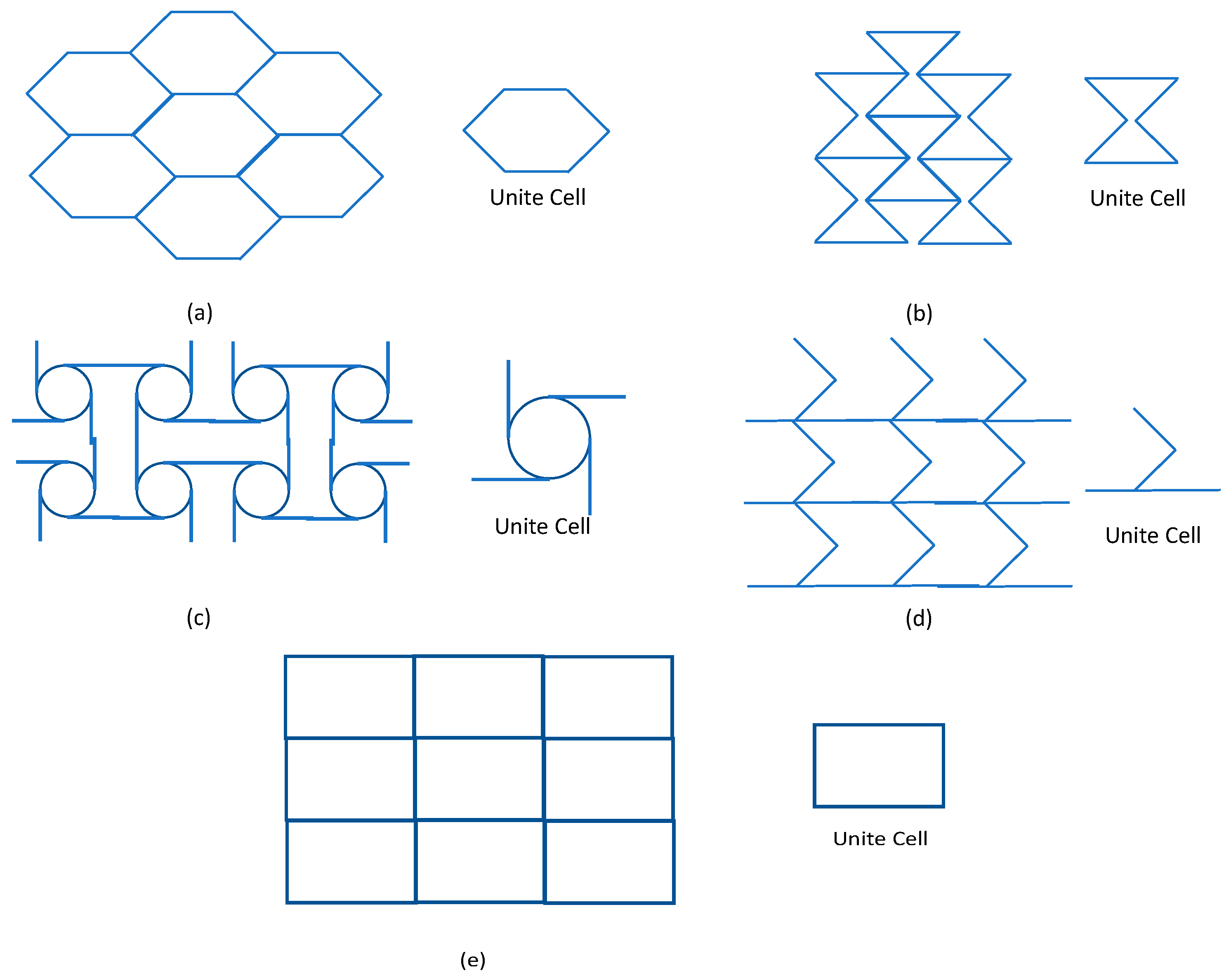
Figure 7.
Computational models selected for this study: (a) honeycomb, (b) auxetic, (c) chiral, (d) zero Poisson’s ratio honeycomb, and (e) square lattices.
Figure 7.
Computational models selected for this study: (a) honeycomb, (b) auxetic, (c) chiral, (d) zero Poisson’s ratio honeycomb, and (e) square lattices.
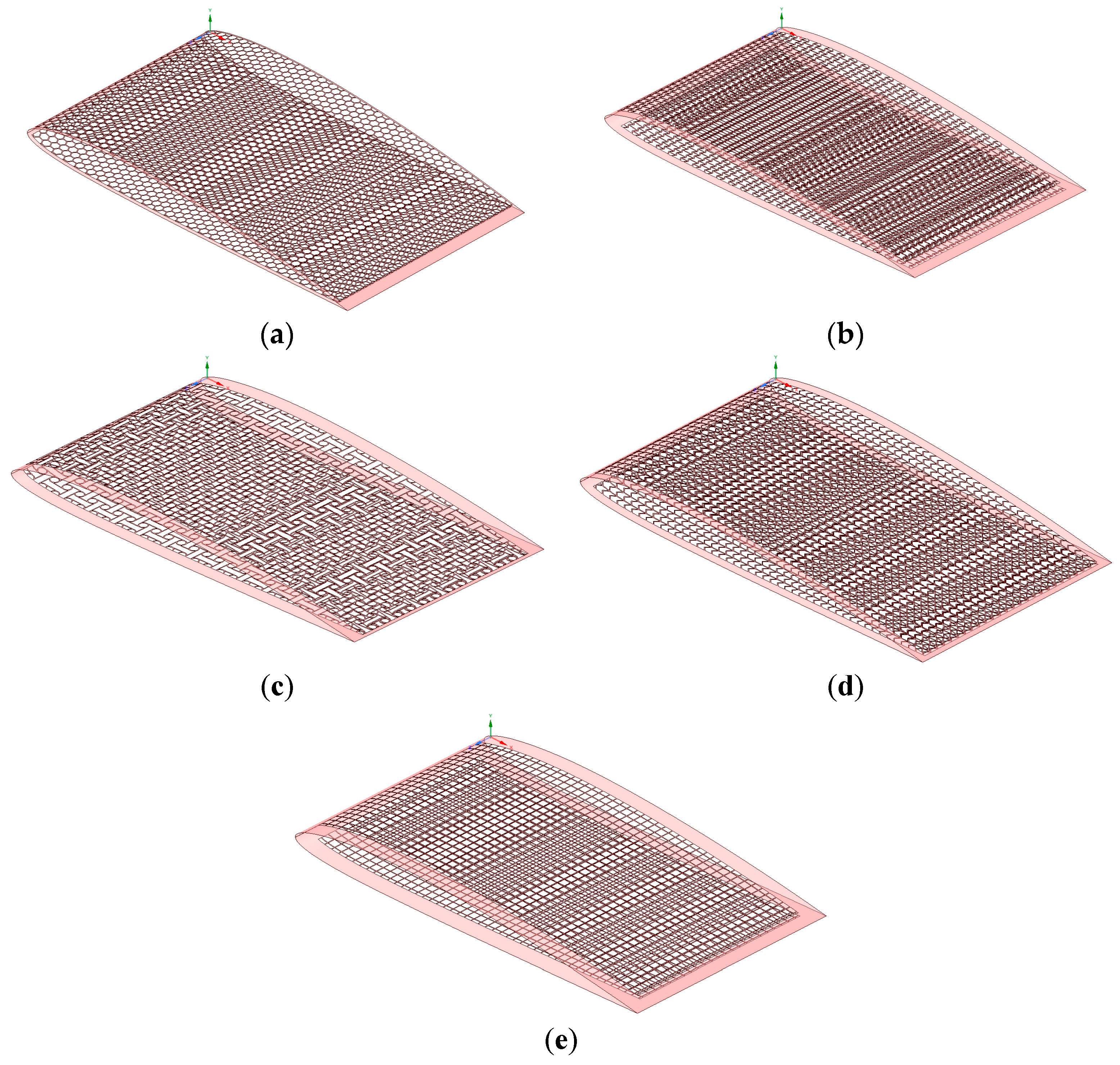
Figure 8.
Zero Poisson’s ratio honeycomb.

Figure 9.
FEM (Finite Element Model) computational verification with analytical in-plane stiffness for a zero Poisson’s ratio skin.
Figure 9.
FEM (Finite Element Model) computational verification with analytical in-plane stiffness for a zero Poisson’s ratio skin.

Figure 10.
Result of mesh independency study of base-skin model.

Figure 11.
Stress/strain curve of acrylonitrile butadiene styrene (ABS) Plus.

Figure 12.
Some of the material properties for selected models: (a) honeycomb, (b) auxetic, (c) chiral, (d) zero Poisson’s ratio honeycomb, and (e) square lattices in x, y, and z axes respectively.
Figure 12.
Some of the material properties for selected models: (a) honeycomb, (b) auxetic, (c) chiral, (d) zero Poisson’s ratio honeycomb, and (e) square lattices in x, y, and z axes respectively.
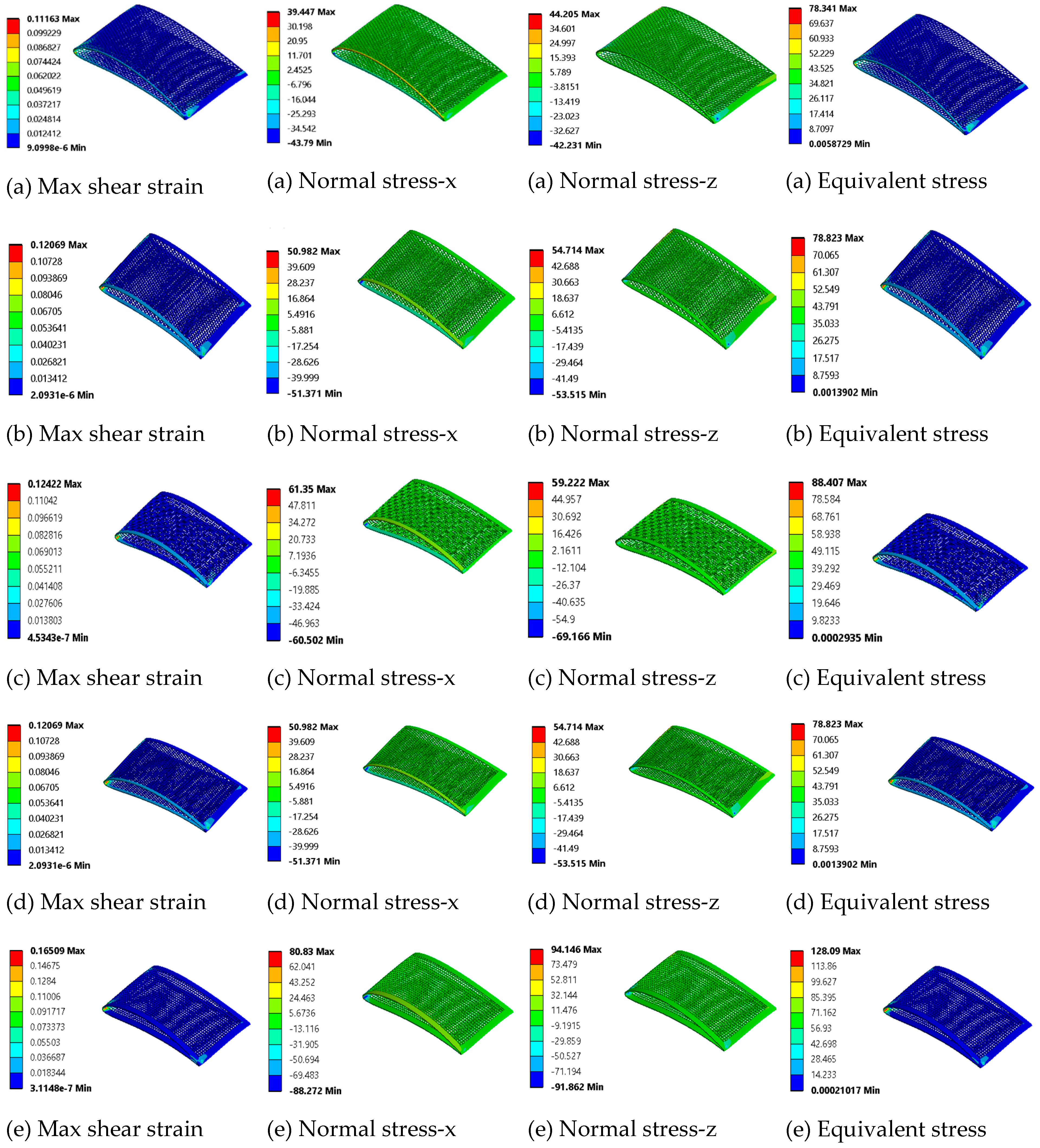
Figure 13.
Selected models’ out-of-plane deformation for the linear morphing case: (a) honeycomb, (b) auxetic, (c) chiral, (d) zero Poisson’s ratio honeycomb, and (e) square lattices.
Figure 13.
Selected models’ out-of-plane deformation for the linear morphing case: (a) honeycomb, (b) auxetic, (c) chiral, (d) zero Poisson’s ratio honeycomb, and (e) square lattices.


Table 1.
Detailed specifications of RQ-7, aircraft model for study.
| Parameters | Values | Parameters | Values |
|---|---|---|---|
| Wing Span | 1.828 m | Wing Chord | 0.54 m |
| Wing Skin Thickness | 4.6 kg/m2 | Spar Location | 40% from leading edge |
| Morphing Range | Fixed wing | Takeoff Weight | 1452 N |
| Empty Weight | 823.8 N | Gross Weight | 1646.8 N |
Table 2.
Wing boundary conditions and their perspective coordinates.
| Parts | X Coordinate (mm) | Y Coordinate (mm) | Z Coordinate (mm) |
|---|---|---|---|
| Spar | 216 | 0 | 0–1828.78 |
| Fuselage (fixed end) | 0–540 | 0 | 0–40 |
| Actuator 1 | 0–540 | 0 | 298.13–338.13 |
| Actuator 2 | 0–540 | 0 | 596.26–636.26 |
| Actuator 3 | 0–540 | 0 | 894.39–934.39 |
| Actuator 4 | 0–540 | 0 | 1192.52–1232.52 |
| Actuator 5 | 0–540 | 0 | 1490.65–153.65 |
| Actuator 6 (free end) | 0–540 | 0 | 1788.78–1828.78 |
Table 3.
Flexible skin models’ mechanical properties for the step morphing case.
| Lattice Skin | Max Shear Strain | Normal Stress-x (MPa) | Normal Stress-z (MPa) | Equivalent Stress (MPa) | ||||
|---|---|---|---|---|---|---|---|---|
| Max. | Min. | Max. | Min. | Max. | Min. | Max. | Min. | |
| Honeycomb | 0.112 | 0.0 | 39 | −44 | 44 | −42 | 78 | 0 |
| Auxetic | 0.121 | 0.0 | 51 | −51 | 54 | −54 | 79 | 0 |
| Chiral | 0.124 | 0.0 | 61 | −60 | 59 | −69 | 88 | 0 |
| Zero Poisson Ratio | 0.121 | 0.0 | 51 | −51 | 55 | −54 | 79 | 0 |
| Square | 0.165 | 0.0 | 81 | −88 | 94 | −92 | 128 | 0 |
Table 4.
Selected models’ directional deformation for the linear morphing case.
| Lattice Skin | Directional Deformation-X (mm) | Directional Deformation-Y (mm) | Directional Deformation-Z (mm) | |||
|---|---|---|---|---|---|---|
| Max. | Min. | Max. | Min. | Max. | Min. | |
| Honeycomb | 0.63 | −2.59 | 10.6 | −27.1 | 1.31 | −0.79 |
| Auxetic | 0.75 | −2.96 | 15.1 | −31.5 | 0.43 | −0.95 |
| Chiral | 0.79 | −3.29 | 13.69 | −33.01 | 0.52 | −1.03 |
| Zero Poisson’s ratio | 0.98 | −3.13 | 20.33 | −33.97 | 0.88 | −0.96 |
| Square | 0.57 | −1.89 | 8.03 | −21.38 | 0.65 | −0.64 |
© 2019 by the authors. Licensee MDPI, Basel, Switzerland. This article is an open access article distributed under the terms and conditions of the Creative Commons Attribution (CC BY) license (http://creativecommons.org/licenses/by/4.0/).
Share and Cite
MDPI and ACS Style
Alsaidi, B.; Joe, W.Y.; Akbar, M. Computational Analysis of 3D Lattice Structures for Skin in Real-Scale Camber Morphing Aircraft. Aerospace 2019, 6, 79. https://doi.org/10.3390/aerospace6070079
AMA Style
Alsaidi B, Joe WY, Akbar M. Computational Analysis of 3D Lattice Structures for Skin in Real-Scale Camber Morphing Aircraft. Aerospace. 2019; 6(7):79. https://doi.org/10.3390/aerospace6070079
Chicago/Turabian StyleAlsaidi, Bashir, Woong Yeol Joe, and Muhammad Akbar. 2019. "Computational Analysis of 3D Lattice Structures for Skin in Real-Scale Camber Morphing Aircraft" Aerospace 6, no. 7: 79. https://doi.org/10.3390/aerospace6070079
Note that from the first issue of 2016, this journal uses article numbers instead of page numbers. See further details here.