Simplified 2D Skin Lattice Models for Multi-Axial Camber Morphing Wing Aircraft

1
Department of Mechanical and Manufacturing Engineering, Tennessee State University, Nashville, TN 37209, USA
2
KBJ Innovation Co., Nashville, TN 37218, USA
*
Author to whom correspondence should be addressed.
Aerospace 2019, 6(8), 90; https://doi.org/10.3390/aerospace6080090
Submission received: 25 April 2019
/
Revised: 10 July 2019
/
Accepted: 22 July 2019
/
Published: 13 August 2019
(This article belongs to the Special Issue Adaptive/Smart Structures and Multifunctional Materials in Aerospace)
Abstract
:Conventional fixed wing aircraft require a selection of certain thickness of skin material that guarantees structural strength for aerodynamic loadings in various flight modes. However, skin structures of morphing wings are expected to be flexible as well as stiff to structural and coupled aerodynamic loadings from geometry change. Many works in the design of skin structures for morphing wings consider only geometric compliance. Among many morphing classifications, we consider camber rate change as airfoil morphing that changes its rate of the airfoil that induces warping, twisting, and bending in multi-axial directions, which makes compliant skin design for morphing a challenging task. It is desired to design a 3D skin structure for a morphing wing; however, it is a computationally challenging task in the design stage to optimize the design parameters. Therefore, it is of interest to establish the structure design process in rapid approaches. As a first step, the main theme of this study is to numerically validate and suggest simplified 2D plate models that fully represents multi-axial 3D camber morphing. In addition to that, the authors show the usage of lattice structures for the 2D plate models’ skin that will lead to on-demand design of advanced structure through the modification of selected structure.

1. Introduction
Wing morphing is a concept wherein the shape of an aircraft’s wing is altered in a continuous manner to suit the desired flight conditions. This change can occur in many ways: sweep angle, chord length, span length, and airfoil [1,2,3]. Wing morphing mainly aims to minimize fuel consumption by reducing drag forces in corresponding flight modes [4]. Recently, many researchers have moved towards the study of using smart materials and their aerodynamic analysis to investigate shape morphing [5,6]. Among morphing types, camber change in airfoil morphing has been widely studied by many researchers [7,8,9,10], due to its effectiveness and simplicity in implementation.
However, the importance of skin material/structure in camber variable wings has been overlooked due its complexity. Conventional and fixed wing aircraft use 1–2 mm thick aluminum skin in their wings to endure aerodynamic loadings. Additionally, skin structure or material selection plays the role of wrapper around the wing, allowing a maximum out-of-plane deformation of 1–1.5 mm. However, when morphing or active geometry/shape changes in wings are considered, newly induced structural stress to the wing, as well as the associated aerodynamic effects caused by shape changes should be also considered. For example, in chord extension morphing, the skin around the wing is not only desired to be flexible in chord direction, but is also required to maintain out-of-plane or span directional loadings, which makes this design problem challenging.
The advantages of flexible skins include their large deformation capability and low elastic modulus. However, many works in the design of skins for morphing wings, which often use smart materials, only consider geometric or static deformations but not dynamic ones [11,12]. State-of-the-art skin design methodologies are comprehensively surveyed by two articles [13,14]. Kuder et al. [13] made an extensive survey of skin morphing structures, indicating that an interdisciplinary approach is required to bring morphing technology into maturity. Similarly, La et al. [14] conducted another comprehensive survey of flexible skin using composite lattice structures. Three main themes based on the previously mentioned two articles are (1) lattice structure for skin, (2) composite material analysis satisfying requirements, and (3) the form of combinational work of (1) and (2).
First, lattice structures for morphing wing skin have recently gained much attention for their material compliancy optimization in cellular structures. Single and double wall corrugated structures [15,16,17,18,19] were studied to improve structural strength as well as to sustain aerodynamic loads. Also, adding hierarchical sub-structures to these walls is suggested [20,21] to increase the material’s compliancy and to reduce required tension loads for skin morphing. Another series of articles address Chiral structures [22,23,24,25] that have gained special attention due to the bending response as compared to other structures. However, most skin design approaches using lattice structures for morphing wings are (1) limited to in-plane 2D, not taking into consideration the aerodynamic loadings in out-of-plane direction, nor a certain shaped morphing (static) only.
Second, composite skin is one of the techniques expected to overcome this multi-axial design challenge [26,27]. Exemplary works by the authors of [28,29,30,31,32,33,34,35] show extensive studies of the material’s properties for skin such as elastic modulus, shear modulus, relative density, and Poisson’s ratio. Another group of researchers have suggested using carbon nanotubes [36], which have the potential to change the electrical conductivity that responds to structural properties.
However, the suggested skin materials and structures are also limited to 2D geometry only and do not fully address multi-axial morphing. Furthermore, these approaches may solve a specific case in a certain morphing type but are not considered a methodological solution. Alsaidi et al. [37] also analyzed the behavior of conventional skin under multi-dimensional morphing and then showed the anticipated stress, strain, and deformation in multi-axes for a skin structure design. However, this was also not materialized into a model for design.
In summary, a simple geometry-structured material for skin in conventional aircraft is not compliant for multi-axial 3D morphing motions such as warping, twisting, and bending from camber morphing. Most of the works in their approaches are limited to 2D in-plane resolution or out-of-plane improvement, using either smart materials or composite lattice structures, as it is challenging to fit multi-axial 3D morphing into a simple model for design modification.
As a result, the goal of this study is to suggest a simple yet effective approach to designing a compliant 3D skin structure for camber morphing wings. To achieve this, we suggest an approach to simplify the skin design process by establishing the relation between 3D structural characteristics of multi-axial morphing and a simplified 2D plate lattice model, since the lattice structure of a material is designable and parameterizable to meet skin design criteria such as strength, Young’s modulus, Poisson’s ratio, stress/strain, and so on [10,11,12] for future development. In this paper, we aim to clarify the effectiveness of the 2D lattice plate model through structural analysis of a real-scale 3D camber morphing model, structural analysis of various lattice structures, and relation between 3D and 2D stress and strain analysis.
2. Camber Morphing Wing Aircraft
2.1. Aircraft Model
A retired UAV (Unmanned Air Vehicle) model, RQ-7, is selected for this study shown in Figure 1. Dimensions of the wings are 1.828 m in span and 0.54 m in chord direction. However, we now assume wings morph their camber rates up to 6%, with base airfoil NACA2410 as shown in Figure 2. For the purpose of skin design, skin requirement in a conventional fixed wing aircraft is 4.6 kg/m2 with an aluminum sheet that is stiff enough in the out-of-plane direction. The spar is located at 40% from the leading edge (i.e., 216 mm). These specifications are summarized in Table 1.
In our computational model of the wing, evenly spaced ribs, as shown in Figure 2, are positioned and hollow in-between. Each rib can morph up to 6% to realize seamless and conformal camber morphing as expected.
2.2. Wing Model
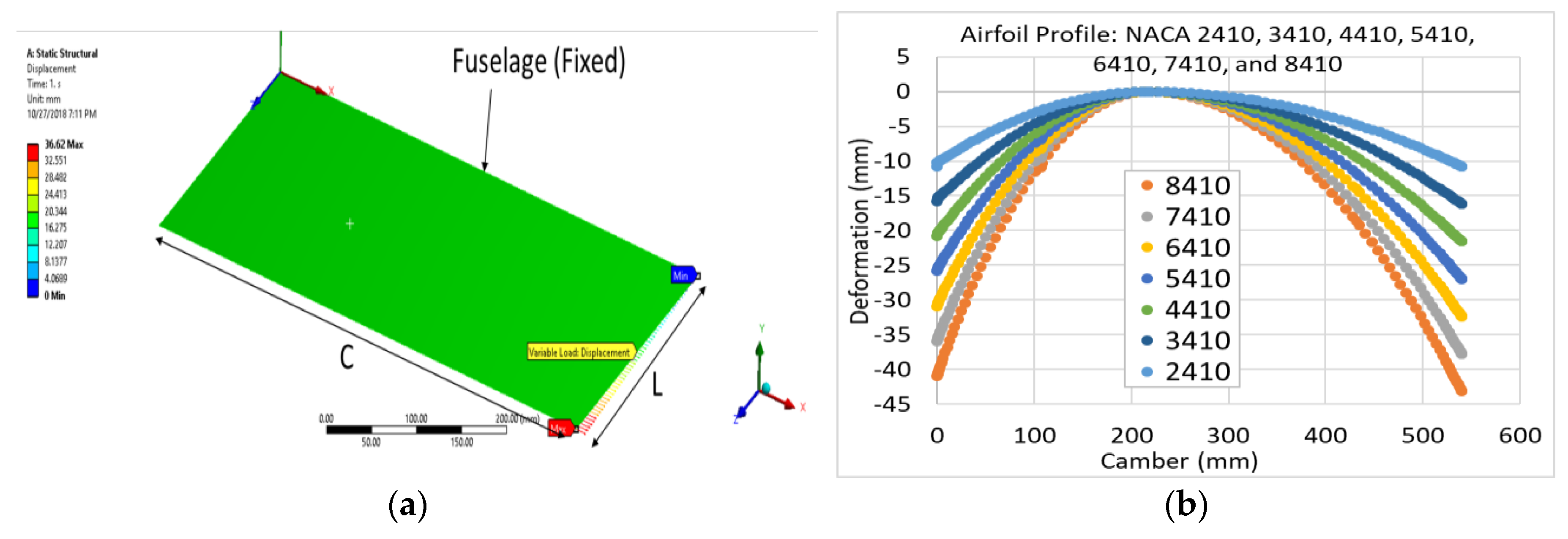
The prototype of the wing for this study is a fixed wing shown below; the wing is fixed at the fuselage side and free at the other end. The camber of the model is capable of deforming to its maximum value (NACA8410 profile) at the free end, while remaining undeformed (NACA2410) at the fixed side. The linearity of displacement is to ensure that the wing remains undeformed in the fixed side (NACA2410) while it achieves the maximum deformation (NACA8410) at the free side.
The attained optimal NACA8410 chamber profile was found when we applied 30.6 mm in the bottom edge leading side and 32.3 mm in the bottom edge trailing side at the free end of wing. ANSYS structural modeler [39] is used in this study. The initial structure was created by forming a wing of NACA2410 profile, which means the wing was free of stresses. Camber can morph at any rate from 2410 to 8410. NACA8410 takes place at the free end, while the fixed end maintains NACA2410. For computational simplicity, a section of two actuators were modeled, as shown in Figure 3a.
2.3. Camber Morphing Model
Skin morphing, as it is known, is the continuous shape changing. In order to achieve such continuity, we need to initially create the internal structure that would be capable of supporting the external skin layer. Therefore, creating the original structure by firstly forming a wing of NACA2410 profile. Then, the wing structure is wrapped by 5 mm of seamless skin composite layer. The material of the designed wing and skin layer are required to be flexible enough to comply with any deformation that it could undergo, without fracture, i.e., Polyethylene or Acrylonitrile Butadiene Styrene copolymer (ABS) composite. Here, the material ABS is selected as one of the 3D printable materials and the mechanical property of the ABS could be found in [39]. The spar is located at 40% from the leading edge and is the only fixed part of the wing. Figure 3b shows the comparisons of the 2D airfoil profiles of NACA2410 and NACA8410.
In the actual systems, the linear DC actuators are positioned where the ribs are, and by adjusting the actuating power, the variable camber wing could have different camber morphing rates in the range up to 6% camber morphing from 2% to 8%. However, in general, the number of actuators depends on the size of the wing and the percentage of camber change. Thus, the challenge to achieve such a profile is because of the reaction of the internal structure of the wing against the applied displacement. The boundary conditions and their perspective coordinates for our model are tabulated in Table 2.
2.4. Internal and External Skin Models
Internal and external skins of FE (finite element) two-layered model are shown in Figure 4. The internal skins (the brown colored region in Figure 4a) will be replaced with the lattice structure for future development that could be customized and optimized at the designers’ discretion. The outer layer, external skin (green colored region in Figure 4a) is the actual skin structure vulnerable to structural and aerodynamic loadings. Both skins were modeled using shell element that has a thickness of 5 mm (internal skin) and 1 mm (external skin). Approximately 1,600,000 elements have used to model these layers. Mechanical properties of external and internal skin were assumed to be homogeneous with no-separation contact. The internal skin is modeled as ABS bulk material to understand its behavior during the morphing process. This material has significant properties that makes it a great option, such as its high strength at low density, high flexibility that complies with the desired input of deformation, and longer life compared to some other plastics. This step is an important benchmark in modeling to develop skin design criteria, which will be discussed in a different study. External skin is assumed to have a stiffness of approximately 1/10 that of the internal skin to passively follow the internal structure. The nature of the morphed wing, which should not undergo any permanent deformation, is assumed to have linear elastic material properties. Note that the gray color area in Figure 4a represents one of the actuators shown in Figure 2.
3. Numerical Analysis
As shown above in Figure 2 and Figure 3, each individual rib is free to morph up to 6%, but they are attached in order to formulate the wing through the spar and skin structure. We picked the first section of a wing from the fuselage, as shown in Figure 3a, with the maximum morphing rate, 6%, to consider the worst case of structural loading where one side is firmly attached to the fuselage with no motion (NACA2410), while the other side is assumed to be at NACA8410. The main interests of analysis were (1) deformation, (2) stress, and (3) strain in all x, y, z directions and x–y, y–z, and z–x planes. First, we used (1) ABS bulk material skin on a real 3D wing model and analyzed correspondences. Then we did the same with (2) the 2D ABS bulk material plate model and (3) the 2D ABS lattice model for computational analysis.
3.1. Wing Model Structural Analysis
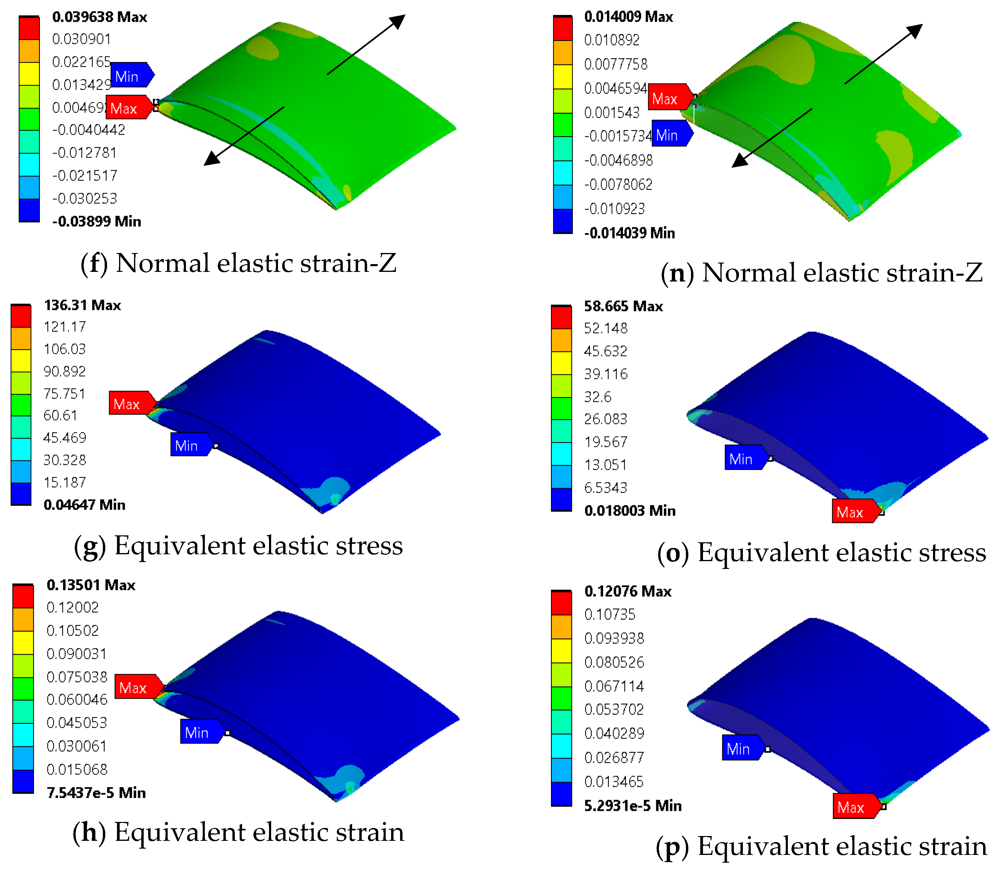
The series of figures in Figure 5 demonstrate all of the important mechanical properties of internal skin (a) and external skin (b) related to bulk material at 6% camber rate. Figures are shown for one section of the wing only, as mentioned above, and deformation is applied at the first section (rib to rib) from the fuselage. This result is tabulated in Table 3. Shear stress and shear strain of both skins were examined to avoid structural failure because of the excessive amount of shear that skins undergo during morphing. As expected, the internal skin experiences much higher shear stress than external skin. The reason is the internal skin has a larger thickness and Young’s modulus of elasticity compared to the external skin as well as for the elastic shear strain, which is larger for the internal skin than the external. This indicates that the external skin passively follows the internal skin’s movement. This means that, at 6% camber rate, the maximum shear strain is 0.066 and the minimum is −0.068 on the internal skin.
Another point is both maximum shear stress and strain are located at the trailing edges of the wing, right at the NACA8410 profile. The expected skin failure is at the actuator’s location, based on this analysis. Furthermore, the internal skin’s normal stresses are twice that of the external skin, as shown in Table 3. Equivalent elastic stress and strain also agree with other stresses, that the material experiences a large amount of stress, way beyond the material’s ability to sustain it at this camber rate.
3.2. 3D Wing Model Aerodynamic Analysis
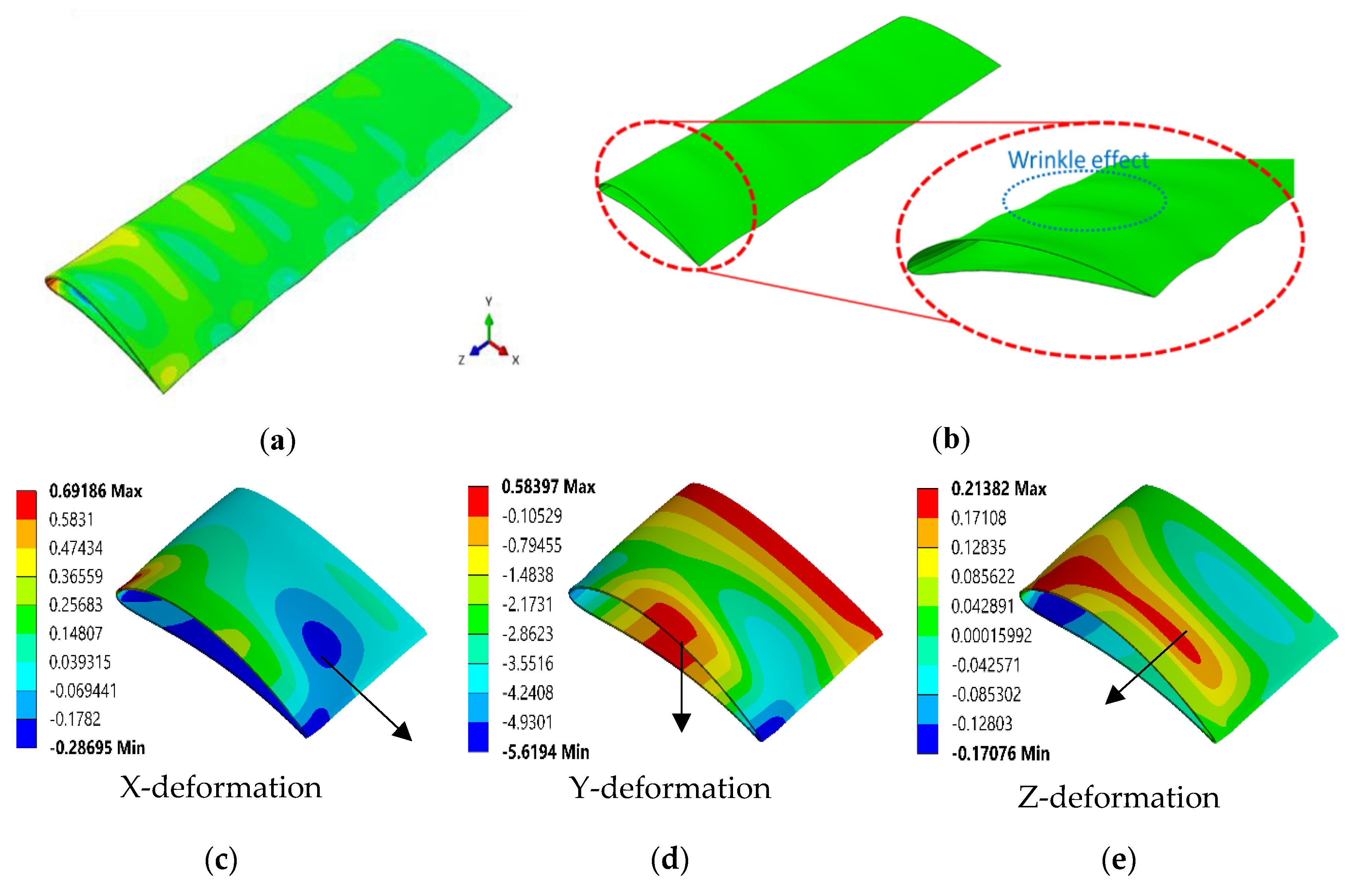
It is important to study the effect of aerodynamic load on the surface of the wing, so that we can identify two things: first, the amount and nature of expected wrinkles on the surface of the wing, and second, examine if the material has the capability to sustain aerodynamic loads. Linear morphing, or a 1% camber rate, is the case that we believe has the largest influence on the skin for aerodynamic study. The reason for such a claim is because the material experiences the least amount of stretch, at a 1% rate, than it does at any other rates. Based on the collected RQ-7 specifications, the empty weight is approximated to be around 823.8 N, while the gross weight is about 1646.8 N. If it is assumed that the top surface of the wing carries 5 times the gross weight (i.e., 5 g load) and the bottom surface carries one time the gross weight (i.e., 1 g load), then pressures on the top and bottom surfaces would be 4171.93 Pa and 834.386 Pa, respectively. Influence of a 5 g load factor on the wing model is shown in Figure 6. The choice of aerodynamic loading 5 g is based on harsh flight conditions in take-off or landing [14]. A wavy pattern is visible, which represents compression and expansion within a short space. During the morphing process, wrinkles on the skin surface emerge. Known as the bulge effect, the wrinkle on the surface has also been observed from previous studies of the morphing wing skin [40]. This is caused by rapid changes in the surface area. The airfoil profile changes from NACA2410 to NACA8410, resulting in about 10% area change on the top surface of the wing skin and about 1% change on the bottom surface. This change in the surface area causes wrinkles on the top surface of the morphing wing skin, as shown in Figure 6. However, the emergence of wrinkles has negative effects in terms of aerodynamic efficiency and aircraft stability. These wrinkles will be discussed in another study.
It is clear from the tabulated result in Table 4 that the external structure undergoes some out-of-plane deformation. According to these results, deformation of the skin is dominant on the y-axis at 5.6 mm (i.e., airfoil thickness direction). Moreover, this deformation is mainly concentrated at the center of the larger area of the wing, which is on the trailing edge side.
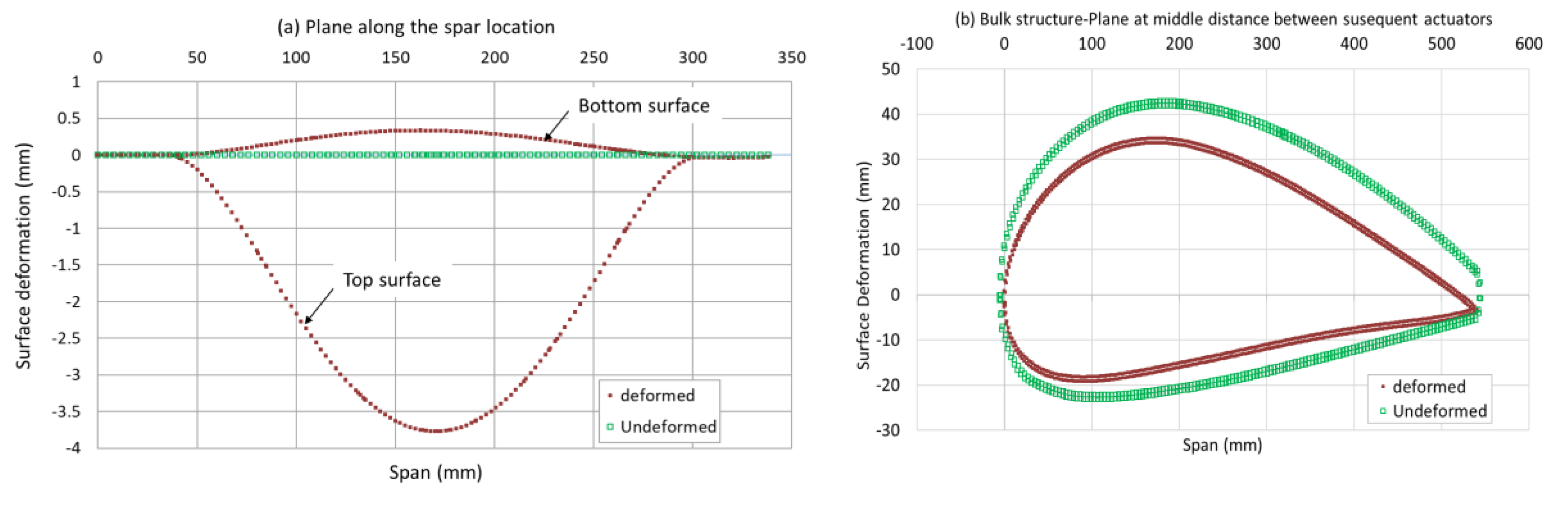
In Figure 7a, the out-of-plane deformation is plotted for the external skin in order to show how the deformation profile is distributed along the surface. As it is expected according to our assumption, the top surface of the skin deforms more than the bottom surface, since it experiences a larger amount of aerodynamic load. However, the top surface deformed a little less than five times that of the bottom surface. Another point to mention, if we look at Figure 7b, is that the external skin can sustain this aerodynamic force with a small amount of twisting, approximately 3/560, or 0.5%. This means with a 5 g load factor, the skin will be twisted clockwise, approximately 0.5%, i.e., 0.1% for each load factor.
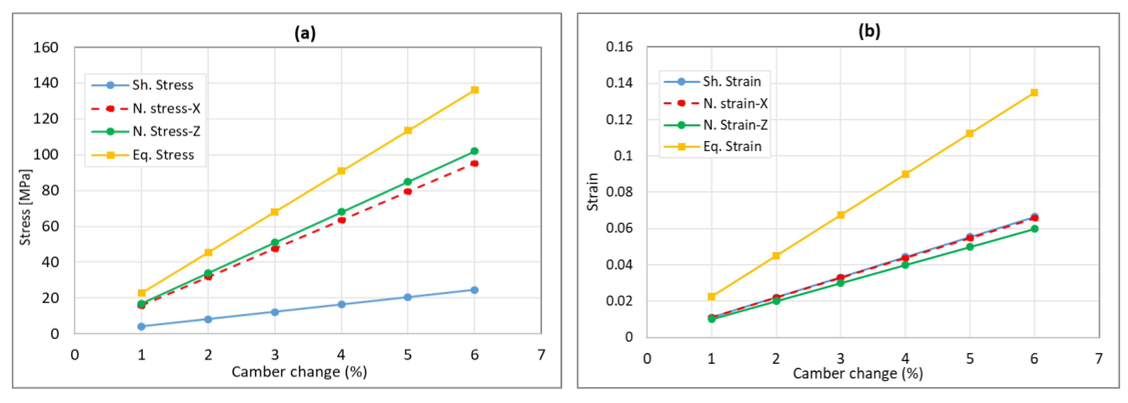
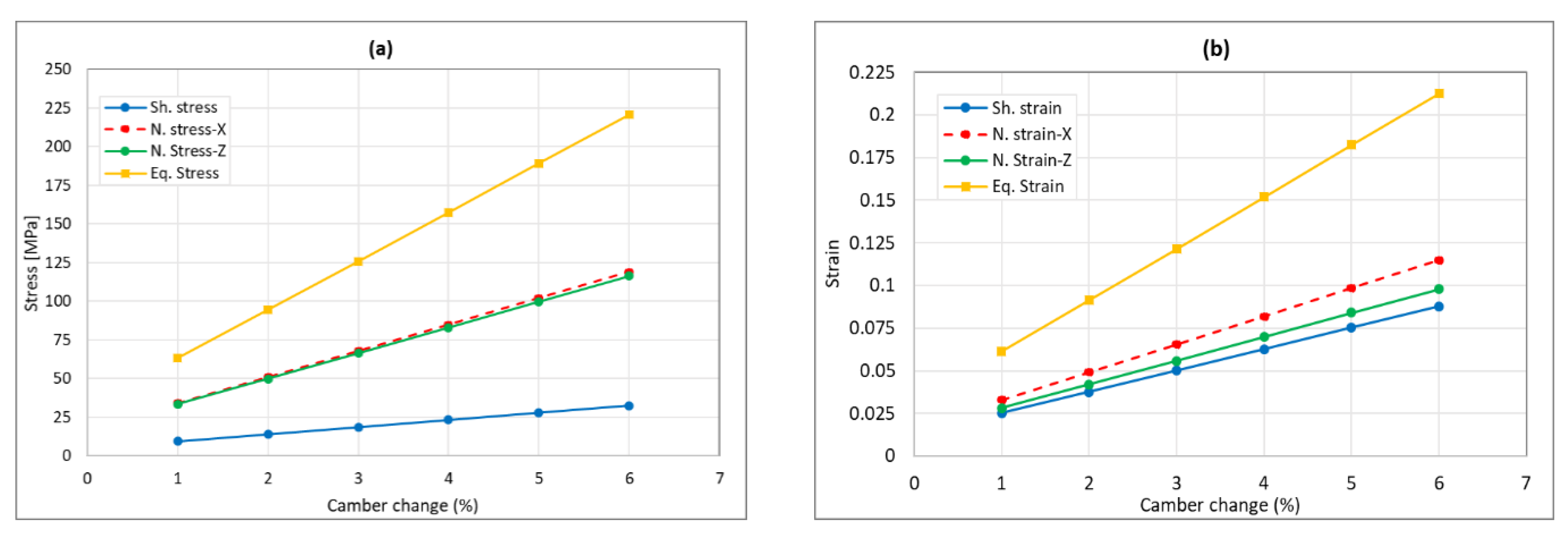
Some of the mechanical properties related to wing morphing have been tested for different input of NACA profiles, i.e., 1% to 6% camber change as shown in Figure 8. When the wing morphs to 6%, the shear stress of ABS bulk material is at 24.6 MPa while the shear strain at 0.066. When the camber rate changes from 2 to 6%, then the shear stress changes from 7 to 24 MPa, normal stress in x-direction from 18 to 97 MPa, and normal stress in z-direction from 18 to 102 MPa, respectively. Furthermore, when the camber rate changes from 2 to 6%, then the normal directional strains in both x and z are from 0.01 to around 0.07. It is noted that the stress and strain are linear to the camber change rate and that the normal stress/strain in x and z are very similar to each other.
3.3. 2D-Plate Bulk Material Structure
The same material, ABS in the previous model but in a 2D-plate model, will be discussed in this section. The dimensions of the model are the same as a real wing model, which are 540 mm and 260 mm in C and L respectfully shown in Figure 9. The boundary conditions of this model are attached to the fuselage at one side, free at the other side, and an in-plane variable input displacement is applied along parameter L to resemble the applied shear deformation in the x–z plane. Note that the thickness of both 3D wing and 2D plate models are 5 mm.
3.4. Lattice Structure for 2D-Plate Model
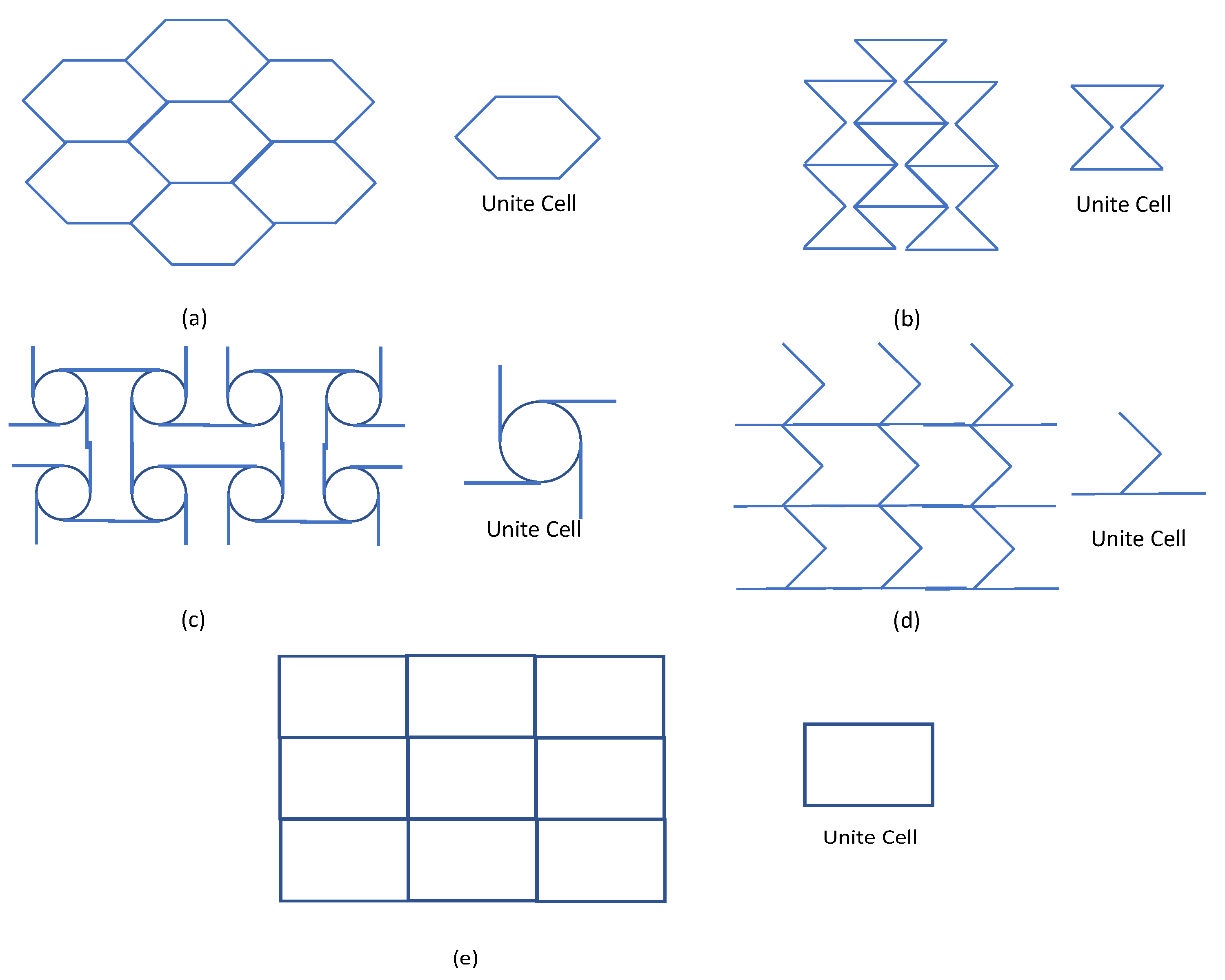
Five lattice structures were selected as basis for design modification and optimization in the future application for skin design. The selected lattice structures are (1) honeycomb, (2) auxetic, (3) chiral, (4) zero-Poisson’s ratio honeycomb, and (5) square lattices, as shown in Figure 11. Each lattice behaves differently in deformation, stress, and strain depending on directions, amount, and boundary conditions of forced input values.
No bulk material has yet been discovered satisfying contradictory requirements of the morphing wing skin based on the variable camber wing. So, the approach authors take here is to design a parameterizable structure such as the lattice structure to satisfy the desired mechanical properties while a fixed material is selected. Therefore, in this section, we demonstrate the behaviors of various lattice structures in their stress/strain. This study plays an important role in selecting the most appropriate lattice structure as a base for future optimization. In total, 5 lattice structures were used: (1) honeycomb, (2) auxetic, (3) chiral, (4) zero-Poisson ratio, and (5) square namely. Dimensions are the same as 2D-plate bulk material. All structures were modeled with the same relative mass density of approximately 0.38.
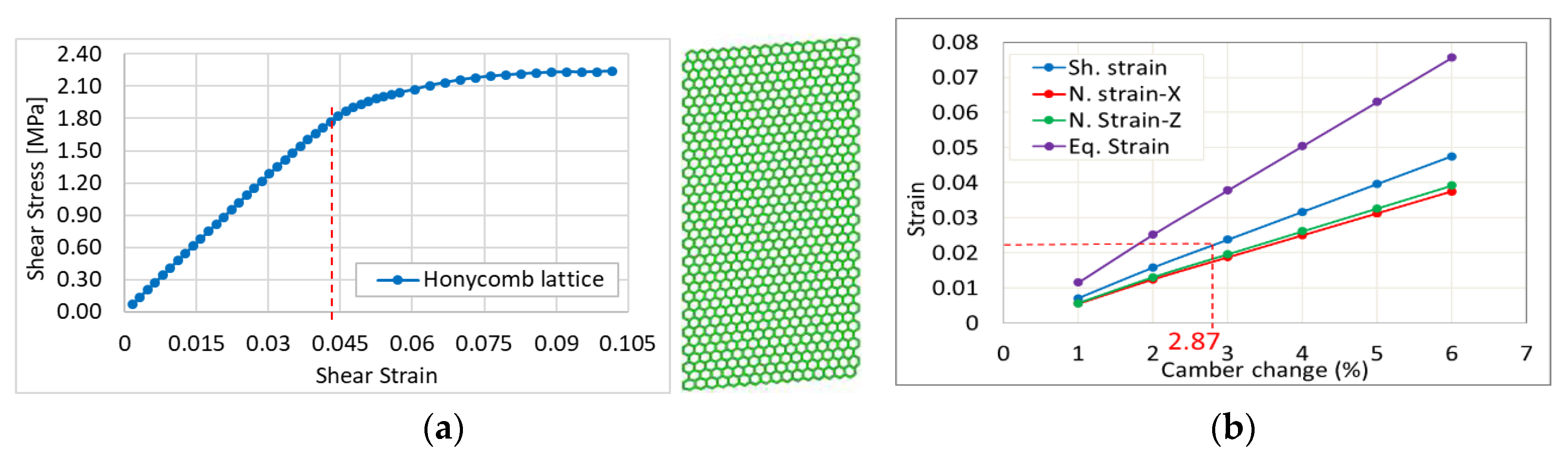
Shear stress and shear strain are very important for two reasons. According to the FE analysis of the wing skin, the shear stress/strain level of the wing skin is dominant compared to the principal strain. This implies that the morphing process is a shearing process. Shear stress often leads to a structural failure on the skin structure of the wing. Therefore, the elastoplastic response of the lattice structures under shear loading was investigated. Here, shear stress is not the shear stress at any point in the lattice structure, but rather, the sum of the reaction forces of the top surface of the lattice structure divided by the area of the top surface when the simple shear loading condition is given to the lattice structure.
- Honeycomb lattice structure: Figure 12 demonstrates the honeycomb lattice 2D-plate model. The achieved result shows that the maximum elastic shear is 0.045, as shown in Figure 12a. If we consider a design safety factor to be two then, the desired elastic shear strain is 0.0225. This means that the expected morphing rate using this type of skin will be 2.87% (Figure 12b). In other words, if we use the honeycomb lattice as a wing cover, then we should not morph a wing more than 2.87%.
- Auxetic lattice structure: an auxetic 2D-plate model is shown in Figure 13. This model performs a more suitable shear elastic strain compared to other models. The achieved result shows that the maximum elastic shear is 0.09, as shown in Figure 13a. Thus, the desired elastic shear strain will be 0.045. This means that the expected morphing rate using this model will be 5.76% (Figure 13b).
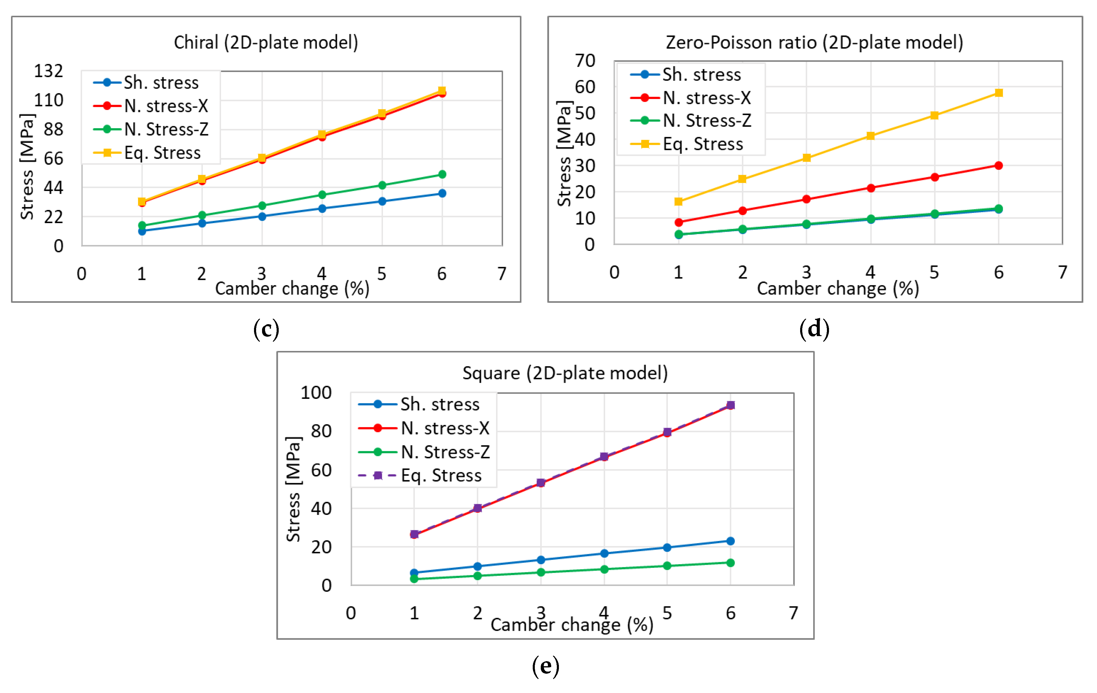
- Chiral lattice structure: a 2D-plate model for this model is shown in Figure 14. The maximum elastic shear strain is found to be 0.075. This means that the desired shear strain is 0.0375 when considering a 2 factor of safety. This result means that the maximum expected camber change using this type of structure will be 3.57% as shown in Figure 14b. The structure consumes a large amount of power to perform the morphing, as compared to other structures based on this result.
- Zero-Poisson ratio lattice: Figure 15 demonstrates the 2D-plate model for the zero-Poisson ratio lattice. The achieved result shows that the maximum elastic shear is 0.078 as shown in Figure 15a. Therefore, the desired elastic shear strain will be 0.039 which means that the expected morphing rate using this model will be 2.6% as shown in Figure 15b.
Each lattice structure of the same dimension and density has been studied for their s–s curve (stress vs. strain).
The most appropriate lattice structure is auxetic, allowing morphing up to nearly 6% while still considering a safety factor 2 in the design perspectives. The series of figures in Figure 17 show the stress vs. percentage of the camber change in the 5 different lattice structures.
4. Comparison between 2D and 3D Models in Bulk and Lattice Structures
In this section, we clarify the relation between the 3D morphing wing model and the 2D plate lattice model in their stress and strain, so as to suggest a simplified lattice model for future modification. Normal stress in x and z directions, shear stress in x–z plane, and equivalent stress are discussed here for comparison.
- Normal stress along x-direction (chord): the trendline for the 2D-plate model is y = 1036.9x or, mplate = 1036.9, while the wing is y = 1448.8x, or mwing = 1448.8. This means that the ratio, r, which is the result of dividing these trendlines with each other, will be 1.39. This translates when the normal strain-x of plate model is 0.0493, which is the case a 2% camber change, then the expected equivalent normal stress-x for 3D wing model will be r × mplae × x, or 1.39 × 1036.9 × 0.0493, which is 71.1 MPa for morphing a wing model.
- In-plane shear stress: the trendline for 2D-plate is the same for the wing, which is y = 370.36x or, mplate = 370.36. This means that the ratio r will be 1.0. This could be translated that when the in-plane shear strain of the plate model is 0.038, which is the case for a 2% camber change, then the expected equivalent in-plane shear stress for the wing model will be r × mplae × x, or 1.0 × 370.36 × 0.038, which is 14.1 MPa for morphing a wing model.
- Normal stress along z-direction (span): the trendline for 2D-plate model is y = 1187.3x or, mplate = 1187.3, while for the wing is y = 1706x, or mwing = 1706. This means that the ratio r will be 1.43. This could be translated that when the normal strain-z of the plate model is 0.042, which is the case for a 2% camber change, then the expected equivalent normal stress-z for the wing model will be r × mplae × x, or 1.43 × 1187.3 × 0.042, which is 102.5 MPa for morphing a wing model.
- Equivalent stress: the trendline for 2D-plate model is y = 1009.7x or, mplate = 1009.7, while for the wing is y = 1037x, or mwing = 1037. This means that the ratio r will be 1.03. This could be translated that when the equivalent strain of the plate model is 0.091, which is the case for a 2% camber change, then the expected equivalent stress for the wing model will be r × mplae × x, or 1.03 × 1009.7 × 0.091, which is 71.3 MPa for morphing a wing model.
5. Summary
We first modeled the two-layered ABS bulk material 3D skin and analyzed the effect under morphing. Then, we modeled a 2D-plate model that had the same dimensions, with 3D skin. After that, we applied the same NACA profile displacements to both models. Finally, we compared some of the mechanical properties for both models.
The relation between the actual 3D model and a simplified 2D plate lattice model is summarized in Table 5, x- and z-directional normal stresses, x–z (in-plane) shear stress, and equivalent stress respectively. The ratio r in Table 5 clarifies the functional relation of each lattice structure (2D model) for the actual 3D wing model under a morphing of up to 6%.
6. Conclusions and Discussion
Skin is the most vulnerable to structural and aerodynamic loadings in flight. While conventional fixed wing aircraft use 1–2 mm thick aluminum skin stiff enough to endure aerodynamic loadings, morphing wing skins are under additional structural stress from geometry change and induced reactions to aerodynamic loadings. Many related works are only limited to 2D in-plane analysis for design modification, not taking into consideration aerodynamic loadings. Furthermore, most of the works aim to remedy a certain structural stress through a material selection, which is not a methodological solution. Therefore, we set out to design advanced skin structure in camber morphing wing aircraft that is flexible in targeted axes but stiff enough in other directional loadings. As a first step, within the scope of camber morphing that warp, twist, and bend in 3D, we show the comprehensive numerical studies of deformation, stress, and strain of skin models in camber morphing wings, and suggest an effective methodology using 2D plate lattice structures.
The validated 3D and 2D models are almost identical in their behaviors of in-plane (x–z plane) shear stress/strain. This implies that the 2D plate models are good representations of the actual 3D camber morphing wing model to the extent of design optimization.
Author Contributions
Conceptualization, W.Y.J. and M.A.; Methodology, W.Y.J., M.A. and B.A.; Software, B.A.; Validation, W.Y.J., M.A. and B.A.; Writing-original draft preparation, W.Y.J. and B.A.; Writing-review and editing, W.Y.J. and B.A.; Supervision, W.Y.J.; Project administration, W.Y.J.; Funding acquisition, W.Y.J.; Data curation, M.A. and B.A.
Funding
This material is based upon work supported by the DOE (Department of Energy) Research under award number DE-NA0003867.
Conflicts of Interest
The authors declare no conflict of interest.
References
- Sun, J.; Guan, Q.; Liu, Y.; Leng, J. Morphing aircraft based on smart materials and structures: A state-of-the-art review. J. Intell. Mater. Syst. Struct. 2016, 27, 2289–2312. [Google Scholar] [CrossRef]
- Prisacariu, V.; Sandru, V.; Rău, C. Introduction morphing technology in unmanned aircraft vehicles (UAV). In Proceedings of the International Conference of Scientific Paper AFASES 2011, Brasov, Romania, 26–28 May 2011. [Google Scholar]
- Min, Z.; Kien, V.K.; Richard, L.J.Y. Aircraft morphing wing concepts with radical geometry change. IES J. Part A Civ. Struct. Eng. 2010, 3, 188–195. [Google Scholar] [CrossRef]
- Kammegne, M.J.T.; Botez, R.M.; Grigorie, L.T.; Mamou, M.; Mébarki, Y. Proportional fuzzy feed-forward architecture control validation by wind tunnel tests of a morphing wing. Chin. J. Aeronaut. 2017, 30, 561–576. [Google Scholar] [CrossRef]
- Barbarino, S.; Bilgen, O.; Ajaj, R.M.; Friswell, M.I.; Inman, D.J. A Review of Morphing Aircraft. J. Intell. Mater. Syst. Struct. 2011, 22, 823–877. [Google Scholar] [CrossRef]
- Ajaj, R.M.; Beaverstock, C.S.; Friswell, M.I. Morphing aircraft: The need for a new design philosophy. Aerosp. Sci. Technol. 2016, 49, 154–166. [Google Scholar] [CrossRef] [Green Version]
- De Gaspari, A.; Riccobene, L.; Ricci, S. Design, Manufacturing and Wind Tunnel Validation of a Morphing Compliant Wing. J. Aircr. 2018, 55, 2313–2326. [Google Scholar] [CrossRef] [Green Version]
- Cooper, J.E.; Chekkal, I.; Cheung, R.C.M.; Wales, C.; Allen, N.J.; Lawson, S.; Peace, A.J.; Cook, R.; Standen, P.; Hancock, S.D.; et al. Design of a Morphing Wingtip. J. Aircr. 2015, 52, 1394–1403. [Google Scholar] [CrossRef] [Green Version]
- Chekkal, I.; Cheung, R.; Wales, C.; Cooper, J.E.; Allen, N.; Lawson, S.; Peace, A.J.; Hancock, S.; Cook, R.; Standen, P.; et al. Design of a morphing wing tip. In Proceedings of the AIAA SciTech 22nd AIAA/ASME/AHS Adaptive Structures Conference, National Harbor, MD, USA, 13–17 January 2014. [Google Scholar]
- Li, D.; Zhao, S.; Da Ronch, A.; Xiang, J.; Drofelnik, J.; Li, Y.; Zhang, L.; Wu, Y.; Kintscher, M.; Monner, H.P.; et al. A review of modelling and analysis of morphing wings. Prog. Aerosp. Sci. 2018, 100, 46–62. [Google Scholar] [CrossRef] [Green Version]
- Thill, C.; Etches, J.; Bond, I.; Potter, K.; Weaver, P. Composite corrugated structures for morphing wing skin applications. Smart Mater. Struct. 2010, 19, 124009. [Google Scholar] [CrossRef]
- Vingliotti, A.; Pasini, D. Analysis and design of lattice materials for large cord and curvature variations in skin panels of morphing wings. Smart Mater. Struct. 2015, 24, 037006. [Google Scholar] [CrossRef]
- Kuder, I.K.; Arrieta, A.F.; Raither, W.E.; Ermanni, P. Variable stiffness material and structural concepts for morphing applications. Prog. Aerosp. Sci. 2013, 63, 33–55. [Google Scholar] [CrossRef]
- La, S.; Joe, W.Y.; Akbar, M.; Alsaidi, B. Surveys on Skin Design for Morphing Wing Aircraft: Status and Challenges. In Proceedings of the 2018 AIAA Aerospace Sciences Meeting, AIAA SciTech Forum, (AIAA), Kissimmee, FL, USA, 8–12 January 2018. [Google Scholar] [CrossRef]
- Takahashi, H.; Yokozeki, T.; Hirano, Y. Development of variable camber wing with morphing leading and trailing sections using corrugated structures. J. Intell. Mater. Syst. Struct. 2016, 27, 2827–2836. [Google Scholar] [CrossRef]
- Bai, J.B.; Chen, D.; Xiong, J.J.; Shenoi, R.A. A corrugated flexible composite skin for morphing applications. J. Compos. Part B 2017, 131, 134–143. [Google Scholar] [CrossRef]
- Navaratne, R.; Dayyani, I.; Woods, B.; Friswell, M.I. Development and Testing of a Corrugated Skin for a Camber Morphing Aerofoil. In Proceedings of the 23rd AIAA/AHS Adaptive Structures Conference, AIAA SciTech Forum, Kissimmee, FL, USA, 5–9 January 2015. [Google Scholar] [CrossRef]
- Previtali, F.; Arrieta, A.F.; Ermanni, P. Double-walled corrugated structure for bending-stiff anisotropic morphing skins. J. Intell. Mater. Syst. Struct. 2015, 26, 599–613. [Google Scholar] [CrossRef]
- Previtali, F.; Molinari, G.; Arrieta, A.F.; Guillaume, M.; Ermanni, P. Design and experimental characterisation of a morphing wing with enhanced corrugated skin. J. Intell. Mater. Syst. Struct. 2016, 27, 278–292. [Google Scholar] [CrossRef]
- Sun, Y.; Pugno, N.M. In plane stiffness of multifunctional hierarchical honeycombs with negative Poisson’s ratio sub-structures. Compos. Struct. 2013, 106, 681–689. [Google Scholar] [CrossRef]
- Taylor, C.M.; Smith, C.W.; Miller, W.; Evans, K.E. The effects of hierarchy on the in-plane elastic properties of honeycombs. Int. J. Solids Struct. 2011, 48, 1330–1339. [Google Scholar] [CrossRef] [Green Version]
- Mousanezhad, D.; Haghpanah, B.; Ghosh, R.; Hamouda, A.M.; Nayeb-Hashemi, H.; Vaziri, A. Elastic properties of chiral, anti-chiral, and hierarchical honeycombs: A simple energy-based approach. Theor. Appl. Mech. 2016, 6, 81–96. [Google Scholar] [CrossRef] [Green Version]
- Bouakba, M.; Bezazi, A.; Scarpa, F. FE analysis of the in-plane mechanical properties of a novel Voronoi-type lattice with positive and negative Poisson’s ratio configurations. Int. J. Solids Struct. 2012, 49, 2450–2459. [Google Scholar] [CrossRef]
- Chen, Y.J.; Scarpa, F.; Liu, Y.J.; Leng, J.S. Elasticity of anti-tetrachiral anisotropic lattices. Int. J. Solids Struct. 2013, 50, 996–1004. [Google Scholar] [CrossRef] [Green Version]
- Chen, Y.; Wang, L. Harnessing structural hierarchy to design stiff and lightweight phononic crystals. J. Extrem. Mech. 2016, 9, 91–96. [Google Scholar] [CrossRef] [Green Version]
- Chen, Y.; Yin, W.; Liu, Y.; Leng, J. Structural design and analysis of morphing skin embedded with pneumatic muscle fibers. Smart Mater. Struct. 2011, 20, 085033. [Google Scholar] [CrossRef]
- Chen, S.; Chen, Y.; Zhang, Z.; Liu, Y.; Leng, J. Experiment and analysis of morphing skin embedded with shape memory polymer composite tube. J. Intell. Mater. Syst. Struct. 2014, 25, 2052–2059. [Google Scholar] [CrossRef]
- Olympio, K.R.; Gandhi, F. Flexible Skins for Morphing Aircraft Using Cellular Honeycomb Cores. J. Intell. Mater. Syst. Struct. 2010, 21, 1719–1735. [Google Scholar] [CrossRef]
- Qiu, J.; Wang, C.; Huang, C.; Ji, H.; Xu, Z. Smart skin and actuators for morphing structures. In Proceedings of the 23rd International Congress of Theoretical and Applied Mechanics, Procedia IUTAM, Beijing, China, 19–24 August 2012; Volume 10, pp. 427–441. [Google Scholar] [CrossRef]
- Chen, Y.; Li, T.; Jia, Z.; Scarpa, F.; Yao, C.W.; Wang, L. 3D printed hierarchical honeycombs with shape integrity under large compressive deformations. J. Mater. Des. 2018, 137, 226–234. [Google Scholar] [CrossRef] [Green Version]
- Mitschke, H.; Robins, V.; Mecke, K.; Schröder-Turk, G.E. Finite auxetic deformations of plane tessellations. Proc. R. Soc. 2013, 469, 20120465. [Google Scholar] [CrossRef] [Green Version]
- Yang, L.; Harrysson, O.; West, H.; Cormier, D. Mechanical properties of 3D re-entrant honeycomb auxetic structures realized via additive manufacturing. Int. J. Solids Struct. 2015, 69, 475–490. [Google Scholar] [CrossRef]
- Chen, J.; Shen, X.; Li, J. Zero Poisson’s ratio flexible skin for potential two-dimensional wing morphing. J. Aerosp. Sci. Technol. 2015, 45, 228–241. [Google Scholar] [CrossRef]
- Olympio, K.R.; Gandhi, F. Zero Poisson’s Ratio Cellular Honeycombs for Flex Skins Undergoing One-Dimensional Morphing. J. Intell. Mater. Syst. Struct. 2010, 21, 1737–1753. [Google Scholar] [CrossRef]
- Ajdari, A.; Jahromi, B.H.; Papadopoulos, J.; Nayeb-Hashemi, H.; Vaziri, A. Hierarchical honeycombs with tailorable properties. Int. J. Solids Struct. 2012, 49, 1413–1419. [Google Scholar] [CrossRef] [Green Version]
- Jakubinek, M.; Ashrafi, B.; Martinez-Rubi, Y.; Laqua, K.; Palardy-Sim, M.; Roy, S.; Rahmat, M.; Sunesara, A.; Dénommée, S.; Simard, B. Multifunctional skin materials based on tailorable, carbon-nanotube-polyurethane composite sheets. In Proceedings of the 2018 AIAA SciTech Forum, Kissimmee, FL, USA, 8–12 January 2018. [Google Scholar] [CrossRef]
- Alsaidi, B.; Akbar, M.; La, S.; Joe, W.Y.; You, H.; Kim, S.; Yun, G. Modeling and Stress Analysis of Composite Skin Structure for Camber Morphing Wing. In Proceedings of the 2018 Multidisciplinary Analysis and Optimization Conference, Atlanta, GA, USA, 25–29 June 2018. [Google Scholar] [CrossRef]
- Wikipedia Open Source. Available online: https://en.wikipedia.org/wiki/AAI_RQ-7_Shadow (accessed on 18 October 2018).
- ANSYS. Fluent Theory Guide; Release 17.2; ANSYS Inc.: Cannonsburg, PA, USA, 2016; Available online: https://www.ansys.com/ (accessed on 10 April 2018).
- Tanaka, H.; Okada, H.; Shimasue, Y.; Liu, H. Flexible flapping wings with self-organized microwrinkles. Bioinspir. Biomim. 2015, 10, 046005. [Google Scholar] [CrossRef]
Figure 1.
Selected UAV model RQ-7 shadow [38].
Figure 1.
Selected UAV model RQ-7 shadow [38].

Figure 2.
Computational model of camber morphing wing: actuators 1–6 show the position of the morphable ribs and the fixed spar location.
Figure 2.
Computational model of camber morphing wing: actuators 1–6 show the position of the morphable ribs and the fixed spar location.

Figure 3.
(a) Wing model with some important design parameters and (b) 2D airfoils comparison between NACA2410 and NACA8410.
Figure 3.
(a) Wing model with some important design parameters and (b) 2D airfoils comparison between NACA2410 and NACA8410.

Figure 4.
(a) FE (finite element) model of two-layered skin; (b–d) meshed model.

Figure 5.
Wing model bulk material elastic stresses (MPa) and elastic strains for 6% camber rate (a–h) internal skin, (i–p) external skin.
Figure 5.
Wing model bulk material elastic stresses (MPa) and elastic strains for 6% camber rate (a–h) internal skin, (i–p) external skin.


Figure 6.
Wing model bulk material out-of-plane deformation for 1% camber rate. (a) Entire wing’s out-of-plane deformation, (b) Zoomed wing-tip deformation, (c) X-axial deformation, (d) Y-axial deformation, and (e) Z-axial deformation respectively.
Figure 6.
Wing model bulk material out-of-plane deformation for 1% camber rate. (a) Entire wing’s out-of-plane deformation, (b) Zoomed wing-tip deformation, (c) X-axial deformation, (d) Y-axial deformation, and (e) Z-axial deformation respectively.

Figure 7.
Wing model bulk material out-of-plane deformation for 1% camber rate.

Figure 8.
Wing model; (a) camber rate vs. stress and (b) camber rate vs. strain.

Figure 9.
(a) Acrylonitrile Butadiene Styrene (ABS) 2D-plate model and (b) NACA profiles.

Figure 10.
The 2D-plate model; (a) camber rate vs. stress and (b) camber rate vs. strain.

Figure 11.
A sample lattice structures, unit cell of (a) honeycomb, (b) auxetic, (c) chiral, (d) zero Poisson’s ratio honeycomb, and (e) square lattices.
Figure 11.
A sample lattice structures, unit cell of (a) honeycomb, (b) auxetic, (c) chiral, (d) zero Poisson’s ratio honeycomb, and (e) square lattices.

Figure 12.
(a) In-plane shear stress/strain curve and (b) percentage of camber change vs. corresponding strain.
Figure 12.
(a) In-plane shear stress/strain curve and (b) percentage of camber change vs. corresponding strain.

Figure 13.
(a) In-plane shear stress/strain curve and (b) percentage of camber change vs. corresponding strain.
Figure 13.
(a) In-plane shear stress/strain curve and (b) percentage of camber change vs. corresponding strain.

Figure 14.
(a) In-plane shear stress/strain curve and (b) percentage of camber change vs. corresponding strain.
Figure 14.
(a) In-plane shear stress/strain curve and (b) percentage of camber change vs. corresponding strain.

Figure 15.
(a) In-plane shear stress/strain curve and (b) percentage of camber change vs. corresponding strain.
Figure 15.
(a) In-plane shear stress/strain curve and (b) percentage of camber change vs. corresponding strain.

Figure 16.
(a) In-plane shear stress/strain curve and (b) percentage of camber change vs. corresponding strain.
Figure 16.
(a) In-plane shear stress/strain curve and (b) percentage of camber change vs. corresponding strain.

Figure 17.
Stress vs. percentage of camber change (a) honeycomb, (b) auxetic, (c) chiral, (d) zero-Poisson, and (e) square lattice.
Figure 17.
Stress vs. percentage of camber change (a) honeycomb, (b) auxetic, (c) chiral, (d) zero-Poisson, and (e) square lattice.


Figure 18.
Relationship between 3D wing model and 2D-plate models (comparison result). (a) Actual 3D wing result vs. 2D plate model in corresponding stress and strains, (b) Auxetic lattice structure and its S-S curve, (c) Zero-Poisson ratio lattice structure and its S-S curve, (d) Honeycomb lattice structure and its S-S curve, (e) Chiral lattice structure and its S-S curve, (f) Square lattice structure and its S-S curve.


Table 1.
Detail Specifications of RQ-7, Aircraft Model for Study.
| Parameters | Value | Parameters | Value |
|---|---|---|---|
| Wing span | 1.828 m | Wing chord | 0.54 m |
| Wing skin thickness | 4.6 kg/m2 | Spar location | 40% from leading edge |
| Morphing range | Fixed wing | Takeoff weight | 1452 N |
| Empty weight | 823.8 N | Gross weight | 1646.8 N |
Table 2.
Wing boundary conditions and their perspective coordinates.
| Parts | X Coordinate (mm) | Y Coordinate (mm) | Z Coordinate (mm) |
|---|---|---|---|
| Spar | 216 | 0–1828.78 | 0 |
| Fuselage (fixed end) | 0–540 | 0–40 | 0 |
| Actuator 1 | 0–540 | 298.13–338.13 | 0 |
| Actuator 2 | 0–540 | 596.26–636.26 | 0 |
| Actuator 3 | 0–540 | 894.39–934.39 | 0 |
| Actuator 4 | 0–540 | 1192.52–1232.52 | 0 |
| Actuator 5 | 0–540 | 1490.65–153.65 | 0 |
| Actuator 6 (free end) | 0–540 | 1788.78–1828.78 | 0 |
Table 3.
Bulk material mechanical properties related to wing model 6% camber change.
| Internal Skin | External Skin | ||||
|---|---|---|---|---|---|
| Parameters | Max. Val. | Min. Val. | Parameters | Max. Val. | Min. Val. |
| In-plane shear stress (MPa) | 24.6 | −25.3 | In-plane shear stress (MPa) | 9.6 | −10.2 |
| In-plane shear strain | 0.066 | −0.068 | In-plane shear strain | 0.029 | −0.028 |
| Normal stress-X (MPa) | 95 | −96 | Normal stress-X (MPa) | 64 | −67 |
| Normal strain-X | 0.066 | −0.067 | Normal strain-X | 0.049 | −0.051 |
| Normal stress-Z (MPa) | 102 | −100 | Normal stress-Z (MPa) | 52 | −50 |
| Normal strain-Z | 0.04 | −0.04 | Normal strain-Z | 0.01 | −0.01 |
| Equivalent Stress (MPa) | 136 | 0 | Equivalent Stress (MPa) | 58.6 | 0 |
| Equivalent Strain | 0.135 | 0 | Equivalent Strain | 0.121 | 0 |
Table 4.
Wing model bulk material directional deformation for 1% camber rate.
| Parameters | Max. Val. | Min. Val. |
|---|---|---|
| Directional deformation-X (mm) | 0.692 | −0.287 |
| Directional deformation-Y (mm) | 0.584 | −5.619 |
| Directional deformation-Z (mm) | 0.214 | −0.171 |
Table 5.
Relation between 3D wing model and 2D plate models.
| Type of Skin | Trendline: Plate Model | Trendline: Wing Model | Ratio (r) | |||||||||
|---|---|---|---|---|---|---|---|---|---|---|---|---|
| Shear Stress | Normal Stress-x | Normal Stress-z | Eq. Stress | Shear Stress | Normal Stress-x | Normal Stress-z | Eq. Stress | r1 | r2 | r3 | r4 | |
| Bulk | y = 370.36x | y = 1036.9x | y = 1187.3x | y = 1009.7x | y = 370.36x | y = 1448.8x | y = 1706x | y = 1037x | 1.0 | 1.39 | 1.43 | 1.03 |
| Honeycomb | y = 370.36x | y = 1093.6x | y = 990.3x | y = 1037x | y = 389.52x | y = 1123.5x | y = 1211.5x | y = 1101.8x | 1.05 | 1.03 | 1.22 | 1.06 |
| Auxetic | y = 370.36x | y = 1044x | y = 1041.1x | y = 1036x | y = 370.36x | y = 1448.6x | y = 1487.3x | y = 1026.1x | 1.0 | 1.39 | 1.43 | 0.99 |
| Chiral | y = 370.36x | y = 1021x | y = 1469.2x | y = 1037x | y = 746.74x | y = 1217.3x | y = 1151.5x | y = 1097.8x | 2.01 | 1.19 | 0.78 | 1.06 |
| Zero-Poisson | y = 387.32x | y = 1128.6x | y = 1592.7x | y = 912.18x | y = 370.36x | y = 1099.4x | y = 1259.7x | y = 1024.7x | 0.96 | 0.97 | 0.79 | 1.12 |
| Square | y = 370.36x | y = 1035.8x | y = 1076.4x | y = 1036.7x | y = 370.36x | y = 1101x | y = 1972.2x | y = 1023.2x | 1.0 | 1.06 | 1.83 | 0.99 |
© 2019 by the authors. Licensee MDPI, Basel, Switzerland. This article is an open access article distributed under the terms and conditions of the Creative Commons Attribution (CC BY) license (http://creativecommons.org/licenses/by/4.0/).
Share and Cite
MDPI and ACS Style
Alsaidi, B.; Joe, W.Y.; Akbar, M. Simplified 2D Skin Lattice Models for Multi-Axial Camber Morphing Wing Aircraft. Aerospace 2019, 6, 90. https://doi.org/10.3390/aerospace6080090
AMA Style
Alsaidi B, Joe WY, Akbar M. Simplified 2D Skin Lattice Models for Multi-Axial Camber Morphing Wing Aircraft. Aerospace. 2019; 6(8):90. https://doi.org/10.3390/aerospace6080090
Chicago/Turabian StyleAlsaidi, Bashir, Woong Yeol Joe, and Muhammad Akbar. 2019. "Simplified 2D Skin Lattice Models for Multi-Axial Camber Morphing Wing Aircraft" Aerospace 6, no. 8: 90. https://doi.org/10.3390/aerospace6080090
Note that from the first issue of 2016, this journal uses article numbers instead of page numbers. See further details here.