
Additively Manufactured Robot Gripper Blades for Automated Cell Production Processes

1
Fraunhofer Institute for Production Technology IPT, 52074 Aachen, Germany
2
Laboratory for Machine Tools and Production Engineering (WZL), RWTH Aachen University, 52074 Aachen, Germany
*
Author to whom correspondence should be addressed.
Processes 2022, 10(10), 2080; https://doi.org/10.3390/pr10102080
Submission received: 13 August 2022
/
Revised: 7 October 2022
/
Accepted: 11 October 2022
/
Published: 14 October 2022
(This article belongs to the Special Issue Automation Control Systems & Process Control for Industry 4.0)
Abstract
:The automation of cell production processes demands strict requirements with regard to sterility, reliability, and flexibility. Robots work in such environments as transporting devices for a huge variety of disposables, e.g., cell plates, tubes, cassettes, and other objects. Therefore, the blades of their grippers must be designed to hold all of these different materials in a stable, gentle manner, and in defined positions, which means that the blades require complex geometries. Furthermore, they should have as few edges as possible, so as to be easy to clean. In this report, we demonstrate how these requirements can be met by producing stainless steel robot grippers by additive manufacturing.
1. Introduction
Cell-based therapies are gaining a growing interest in research and industry as they promise efficient therapies for diseases that are hardly or not at all curable today. In order to decrease their production cost as well as to increase quality and product safety, research and industry are putting more and more effort in fully automating these therapies. Examples are the projects StemCellFactory [1], iCellFactory [2], and AutoCRAT, all of which involve cell production platforms that cultivate, modify, and analyze stem cells fully automatically. In the AutoCRAT project, the platforms AUTOSTEM [3] and StemCellDiscovery [4] are being enhanced in order to enable novel cell production and analysis processes.
Many of such production platforms consist of an arrangement of several automated biotechnological devices, which perform the different processing or analysis steps, and a centrally positioned robot, which transfers all needed objects between the stations. These objects can be all kinds of cell plates, tubes, flasks, pipettes, and other components, all of which have different shapes and sizes. In a manual lab, handling of such objects is no problem, as they are developed to be handled by humans. A human hand has flexibility, adaptivity, and a variety of sensory inputs that cannot be attained by most industrial robot grippers today. To the best of the authors’ knowledge, it is not possible to design robot grippers and gripper blades that can handle all of the existing objects used in biotechnological labs. For reliable handling, robot gripper blades need to be custom designed to reliably hold the objects required for the specific production process [5]. Even when the object variety is minimized, several object types with different geometries remain in most cases. In order to solve these issues, one or several of the following three aspects need to be implemented:
- Shape the gripper blades in a way to handle different object sizes and geometries. Depending on the shape and quantity of the different object types, the grippers become more complex and difficult to manufacture.
- Use objects that have standardized surfaces for robot handling. Those are, at least for now, not commercially available for all standard sizes and shapes. Therefore, custom-made objects or adapter pieces that can be fixed onto the objects need to be developed. Both increase cost and presumably add effort in material preparation.
- Use several grippers or gripper blades, which the robot can change between handling actions. However, this increases technical complexity as well as processing time.
To save production time and cost, the first solution should be preferred. The effort for designing and manufacturing complex grippers needs to be invested only once. Hereafter, they amortize themselves.
Another challenge of processing in biotechnological environments is cleanliness and sterility. In order to avoid unwanted dead particles and, even more critically, living organisms and organic structures, strict requirements are defined for such environments in standards and guidelines, the most important of which are the good manufacturing practice (GMP) guidelines [6,7,8]. They demand that air and surfaces be kept antiseptic, especially those that are close to the biologic product, and that processes, materials, movements, and air flows protect the product from contaminants as best as possible. This also implies that all relevant surfaces must be easy to clean and decontaminate; therefore, they must be resistant against the required cleaning agents and sterilization gases, and have a geometry that allows fast and reliable particle removal. With regard to the latter, surfaces should have as few holes or gaps as possible, rounded corners, and a low roughness, which is, according to the state of the art, Ra ≤ 0.8 µm [9].
The ideal material for robot gripper blades in biotechnological applications is stainless steel, as it provides the stability and durability to be used reliably for a long time period, and can withstand most chemical cleaning and sterilizing agents. As of now, the most common way to produce such tools is by subtractive manufacturing, i.e., milling. Modern milling machines have up to five axes, are driven by computerized numerical control (CNC), and are able to produce a huge variety of complex geometries. However, they reach their limits when it comes to undercuts, hollow inclusions, complex radii and curvatures, or fine geometries such as rips or grids [10].
Additive manufacturing (AM) is a novel method for producing metal objects. Currently, several AM technologies are in development, for example, laser metal deposition (LMD) with wire or powder, or laser powder bed fusion (LPBF).
The process principle of LPBF is shown in Figure 1. Laser radiation is used to create a weld track in a powder bed by melting the powder to solid material. Several weld tracks next to each other result in a layer. Hereafter, the powder bed is moved down by the thickness of one layer, and a new layer of powder from the powder reservoir is placed on the previously welded tracks by a recoater. Several melted layers on top of each other result in a solid metal body. In this way, a 3D-printed metal component is created layer by layer from a sliced computer-aided design (CAD) file on top of a build plate [11,12,13,14]. Support structures are added to the part for the purpose of attaching the part to the base plate, for stabilization of overhangs, and for heat dissipation. The support structure needs to be removed afterwards, e.g., by milling or grinding processes, or by manual material removal [13,15].
The layered structure of the components allows much greater geometric design freedom compared to conventional manufacturing technologies [12]. This also makes it possible to round corners and edges easily. In milling, most radii are formed by producing a sharp edge first and then shaping the radius with a special tool. If the object has many radii or a complex curvature, it is difficult to clamp in a stable and defined position. In additive manufacturing, the round edge can be produced immediately, which makes such geometries much simpler to manufacture. However, this may make the addition of support structures necessary.
Another advantage of the opportunities AM provides in geometric design is weight reduction. Many gripper devices, despite being able to lift heavy objects, have limits on the weight of the gripper blades. The reason for this is the momentum of the blades on their bearings, which are more sensitive when opening or closing the gripper. One way to reduce weight is by removing unneeded material wherever possible, e.g., by decreasing thickness and using ribs to maintain stability. Another option is to create hollow sections inside of the component. However, this is not possible for every additive manufacturing technique. In LPBF, for example, every spot that is not welded remains covered with powder; consequently, every hollow section in the finished part is filled with powder. If it is not possible to remove the powder, weight can only be reduced slightly.
The roughness of the part varies depending on the orientation of the surface during the build-up. Top-skin (upward-facing surfaces during build process) and side surfaces have lower roughness and better quality compared to down-skin surfaces (downward-facing surfaces during build process) [16,17]. The printing tolerance of the parts can reach ±0.1 mm; however, it can increase, e.g., due to thermal distortion to ±0.5 mm or more [14]. Post-machining processes increase surface roughness and accuracy. Common post-processes are sand or glass-bead blasting, milling (also fine milling), grinding, and polishing.
In our research, we have used the additive metal manufacturing technology LPBF to produce robot gripper blades for the automated handling of objects in biotechnology. The gripper blade design enables the gripper to hold several materials with different geometries at different positions. Furthermore, we produced several design proposals that are shaped to improve stability and simplify cleaning.
2. Materials and Methods
The gripper blades discussed in this article are designed to be used in the cell production platform StemCellDiscovery [4], mounted on a robot (VS-087, Denso, Kariya, Japan) with servo grippers (SG-00014, P.T.M. Präzisionstechnik GmbH, Gröbenzell, Germany). In order to perform several cell cultivation and analysis processes, several vessels (Table 1) need to be held and transported by the robot. The variety of these vessels has been reduced to a minimum, but some geometries in different orientations still need to be held. These are 50 mL falcon tubes, 5 mL corning tubes, micro titer plates (MTP), pipette holder plates for the liquid handling unit (Microlab STAR, Hamilton Company, Reno, NV, USA), and test cartridges for an endotoxin tester (Endosafe® nexgen-PTS™, Charles River Laboratories, Wilmington, MA, USA) of the platform, as shown in Table 1 and Figure 2.
Furthermore, the gripper blades may not exceed a certain size, and must be shaped to fit in all areas of the platform and to avoid collisions. For example, an MTP needs to be placed onto a microscope that barely leaves space for the robot to move. A schematic visualization of that area is shown in Figure 2, R3.
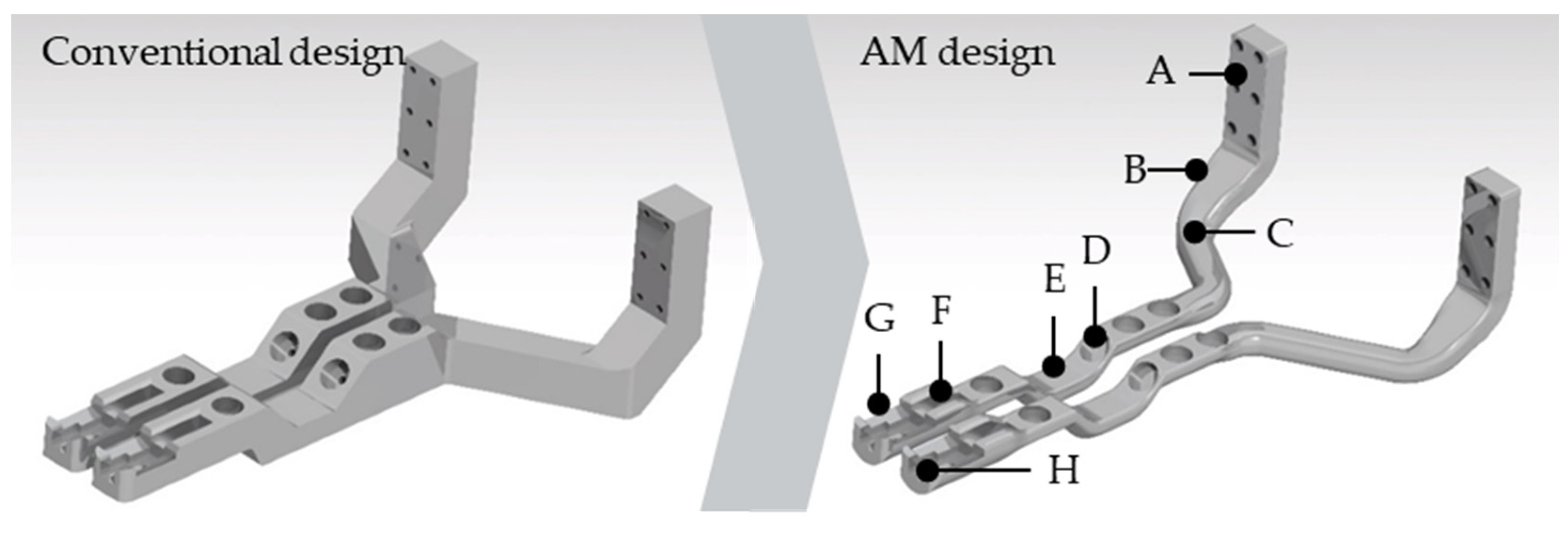
Based on these requirements, the gripper blades were modeled in 3D CAD (Figure 3). On the left side of Figure 3, the first version of the gripper blades is shown, which was designed for conventional production. This design is suitable for manufacturing by milling and die-sinking electrical discharge machining (EDM). It contains geometries for holding round objects, such as tubes, as well as flat objects, such as plates, and special objects, such as test cartridges. Furthermore, the design has an angled geometry, a mounting part to fix them to the robot gripper, and holes to insert rubber parts which improve the grip’s ability to hold objects. However, its shape shows many even surfaces and edges, as such a design is easy and efficient to mill. On the right side of Figure 3, the gripper blades are improved by redesigning them in CAD, so that they can be additively manufactured using LPBF. Here, edged geometries are rounded wherever possible, making the gripper much easier to clean and much lighter, without losing stability. This design would be very challenging for milling, but is suitable for additive manufacturing. The outer dimensions of the gripper blades are shown in Figure 4.
Based on this 3D data, the gripper blades were produced with the LPBF process out of stainless steel SS316L powder with a particle size of 10–45 µm (LPW Technology Ltd., Widnes, UK). The machine tool used was an EOS M290 (EOS GmbH Electro Optical Systems, Krailing, Germany). In order to achieve a good quality of the specific geometrical elements (Figure 3, D–H), these elements were placed face up on the build plate. The orientation and the support structures used are shown in Figure 5A. The block support used (Figure 5A, blue) includes cone supports, which create a strong connection between gripper and base plate and increase the thermal flow, therefore reducing the distortion of the grippers. Block support can be removed easily; thus, the part does not need to be machined completely after printing. After defining placement and support structures of the part, process parameters were set. In order to achieve a high material density, process parameters with an energy density of 57.7 J/mm3 were chosen. The laser power was 214.2 W, the scanning speed was 928.1 mm/s, and the hatch distance was 100 µm. The build-up was carried out with a layer thickness of 0.04 mm, and the process required 8.5 h to produce one set of gripper blades.
After production (Figure 5B), the gripper blades were sawed from the base plate (Figure 5C) and the support structures were removed by hand. Afterwards, the corresponding surfaces were ground. Then, the parts were sand and glass-bead blasted, and, finally, tumbled to smoothen their surface (Figure 5D). After production, glass bead blasting, and tumbling, the surface roughness was measured with an Alicona Infinite Focus G5 (Alicona Imaging GmbH, Raaba, Austria). Finally, fine structures, such as small holes, were added or revised manually, where necessary.
The gripper blades were equipped with rubber pieces in order to increase their grip, and then installed onto the robot gripper of the StemCellDiscovery and tested for handling the intended objects (Figure 5E,F).
3. Results
It took 8.5 h to produce the gripper blades with LPBF. Processing and slicing of the 3D CAD data depends on the computers used and the operator’s skills. For the given sample, the required preparation time was 60 min. After the printing process, support structures were removed and the surfaces were blasted and tumbled for four hours, which took, in total, another five hours. The times for manufacturing the gripper blades shown in Figure 3 (left) with milling were discussed with experts in that field, and were calculated as 16 h for machine preparation and programming, 20 h for machining, and 1.5 h for deburring. All of these times are shown in Figure 6 for comparison.
After printing, only the mounting holes had to be postprocessed by drilling to remove small material residues. In addition, the parts showed a light deformation after being loosened from the base plate, which was corrected by manual bending of the parts. Apart from this, the part showed all geometrical features which had been designed in CAD. Even fine geometries, such as the hooks at the tips of the gripper blades, had been produced in sufficient detail.
The surface of the gripper after LPBF was very rough. The measured roughness of the surface after LPBF production was Ra = 5.9 µm. Sand and glass-pearl blasting reduced it to Ra = 3.4 µm. Tumbling reduced the roughness to Ra = 2.3 µm.
When the volume of the conventional design was compared with the presented design in CAD (Figure 3), weight is reduced by 58% in the additively manufactured part. This was confirmed by weighing the real parts. The conventional design parts had a mass of 228 g and 234 g, while the presented design parts weighed 96 g and 99 g, resulting in weight reductions of 58% in both.
4. Discussion
The robot gripper blades presented here are designed to be able to hold several object types in different orientations.
The parts have a smooth geometry and very few edges, both of which limit space for contaminants to remain and simplify cleaning. However, even glass-pearl blasting and tumbling could not reduce the surface roughness down to the required value of Ra ≤ 0.8 µm. Here, further methods for surface polishing need to be investigated, for which different technologies for mechanical, chemical, or laser-based polishing exist and can be applied [18,19,20,21,22].
The deformation that the parts showed after being removed from the base plate results from thermal stresses during the printing process. These can be prevented by adapting the 3D model before printing, by bending it in the other direction, so that the thermal stresses then form it into the desired geometry.
The only other necessary post-processing was removing small residues from the mounting holes. These holes are intended for M3 screws and are very narrow (i.e., a diameter of 3 mm) to ensure the correct position of the gripper blade on the gripper. In other applications, where the through hole can be bigger in relation to the intended screw size, the holes will probably not need to be postprocessed.
Compared to a model being designed for milling, the design presented here shows a great weight reduction. It would theoretically be possible to reduce volume and weight even further without affecting the LPBF production difficulty or speed; however, this may lead to less smooth surfaces.
The comparison of the manufacturing times with LPBF and milling displayed in Figure 6 shows that the total milling process takes more than twice as long as LPBF. For both methods, great amounts of the manufacturing time consist of machining time, during which processes such as LPBF, milling, or tumbling can run unsupervised. Therefore, the human labor time required is much lower in both cases, as shown in Figure 6. It can also be seen that the human labor time for LPBF is much lower than for milling, which is mainly due to its lower preparation time.
If this or a similar geometry were manufactured by milling, it would need to be milled from a large metal block, 94% of which would be wasted. Another option would be to split it into several parts that would need to be bolted or welded thereafter. This would require additional shapes for mounting, and would lower the geometric accuracy due to additional manufacturing tolerances of the assembling step. In addition, bolted parts can loosen over time, reducing the gripper blades’ reliability or even making them completely unusable.
In both cases, more preparation would be necessary before milling, e.g., CNC programming and loading the corresponding milling tools into the machine. Furthermore, it is likely that some clamps would need to be modified or produced beforehand to hold the part during milling. For milling, the part would need to be processed from several sides, requiring manual reclamping steps. Some geometries, such as the radii (Figure 3, B), would be challenging to manufacture, while others, such as the cartridge pockets (Figure 3, F), would not be possible at all in this form. After milling, however, few or no post-processing steps would be necessary.
A third option for producing such parts would be injection molding or sintering. Both manufacturing techniques require extensive preparations for creating the molds, and are only economic for large part quantities. Moreover, here, some post-processing for removing residues from gate and feeder and milling surfaces with low tolerances are necessary.
For the purpose of manufacturing parts with a geometry similar to those presented here, additive manufacturing techniques such as LPBF appear to be the most efficient. The preparation effort is low, and although the manufacturing time may be long, this method does not require manual interventions and can run automatically and unsupervised. Further advantages of LPBF are a great freedom in geometry and much lower waste of material. Especially for prototyping or custom-made gripper blades, this method shows great promise. If, for example, the geometry of a tube, flask, or plate changes or a new object needs to be handled, new adapted 3D-printed gripper blades can be manufactured easily without much preparation or programming effort. Radii and curvatures are much simpler to realize with LPBF, which simplifies cleaning. In addition, undercuts and pockets can be manufactured easily, which provides many more options for geometries to grip and hold objects.
Two major weakness of LPBF compared to milling are manufacturing tolerances and surface roughness. Where needed, these surfaces should be smoothed after printing, e.g., by means of grinding, polishing, sandblasting, or glass-bead blasting. If most surfaces of the parts have such requirements, manufacturing by milling may be more efficient. Furthermore, milling or injection molding is likely to be cheaper when it comes to mass production. On the other hand, the research in additive manufacturing of metal parts is developing quickly, and may one day become the gold standard for manufacturing all kinds of robot grippers in biotechnological applications.
Especially for biotechnological applications of robot gripper blades, LPBF is a suitable and efficient manufacturing process. Due to strict guidelines, stainless steel is the ideal material for gripper blades, and a curved and rounded geometry simplifies cleaning and decontamination. Biotechnological processes can require handling a high variety of different objects, some of which are not even designed for robotic handling. The freedom in geometric design possible with LPBF enables a user to create one set of gripper blades that is able to hold all required objects reliably. This has been proven with successful tests of the gripper blades presented in this paper, which were used in the StemCellDiscovery to hold and transport all required objects. Further advantages are lightweight designing, flexible adaption, and unsupervised production.
In summary, the LPBF production method shows great potential for manufacturing complex geometries such as robot gripper blades in automated biotechnological environments. Once remaining issues, such as the surface structure, are solved, LPBF could become the ideal manufacturing method for such devices.
Author Contributions
Conceptualization, F.B.; writing—original draft preparation, F.B. and S.G.; writing—review and editing, F.B. and S.G.; supervision, T.B. and R.H.S.; project administration, R.H.S.; funding acquisition, T.B. and R.H.S. All authors have read and agreed to the published version of the manuscript.
Funding
The project AutoCRAT has received funding from the European Union’s Horizon 2020 research and innovation program under grant agreement No 874671. The materials presented and views expressed here are the responsibility of the author(s) only. The EU Commission takes no responsibility for any use made of the information set out.
Institutional Review Board Statement
Not applicable.
Informed Consent Statement
Not applicable.
Data Availability Statement
Not applicable.
Conflicts of Interest
The authors declare no conflict of interest.
References
- Elanzew, A.; Nießing, B.; Langendoerfer, D.; Rippel, O.; Piotrowski, T.; Schenk, F.; Kulik, M.; Peitz, M.; Breitkreuz, Y.; Jung, S.; et al. The StemCellFactory: A Modular System Integration for Automated Generation and Expansion of Human Induced Pluripotent Stem Cells. Front. Bioeng. Biotechnol. 2020, 8, 580352. [Google Scholar] [CrossRef]
- Brecher, C.; Herfs, W.; Malik, A.; Valest, C.; Wein, S.; Wanek, P.; Zenke, M. Adaptive Automatisierung für die Zellproduktion: Mechatronische Rekonfigurierbarkeit von Produktionsanlagen. GIT Labor-Fachz. 2016, 60, 27–39. [Google Scholar]
- Ochs, J.; Hanga, M.P.; Shaw, G.; Duffy, N.; Kulik, M.; Tissin, N.; Reibert, D.; Biermann, F.; Moutsatsou, P.; Ratnayake, S.; et al. Needle to needle robot-assisted manufacture of cell therapy products. Bioeng. Transl. Med. 2022, 7, e10387. [Google Scholar] [CrossRef]
- Ochs, J.; Biermann, F.; Piotrowski, T.; Erkens, F.; Nießing, B.; Herbst, L.; König, N.; Schmitt, R.H. Fully Automated Cultivation of Adipose-Derived Stem Cells in the StemCellDiscovery—A Robotic Laboratory for Small-Scale, High-Throughput Cell Production Including Deep Learning-Based Confluence Estimation. Processes 2021, 9, 575. [Google Scholar] [CrossRef]
- Biermann, F.; Mathews, J.; Nießing, B.; König, N.; Schmitt, R. Automating Laboratory Processes by Connecting Biotech and Robotic Devices—An Overview of the Current Challenges, Existing Solutions and Ongoing Developments. Processes 2021, 9, 966. [Google Scholar] [CrossRef]
- European Commission. EudraLex—Volume 4—Good Manufacturing Practice (GMP) Guidelines. Available online: https://ec.europa.eu/health/documents/eudralex/vol-4 (accessed on 3 May 2021).
- 13.040.35 (DIN EN ISO 14644-1:2015); Reinräume und Zugehörige Reinraumbereiche—Teil 1: Klassifizierung der Luftreinheit anhand der Partikelkonzentration. DIN Deutsches Institut für Normung e.V.: Berlin, Germany, 2016.
- 13.040.35 (DIN EN 17141:2021); Reinräume und Zugehörige Reinraumbereiche—Biokontaminationskontrolle. DIN Deutsches Institut für Normung e.V.: Berlin, Germany, 2021.
- Bobe, U.; Wildbrett, G. Anforderungen an Werkstoffe und Werkstoffoberflächen bezüglich Reinigbarkeit und Beständigkeit. Chem. Ing. Tech. 2006, 78, 1615–1622. [Google Scholar] [CrossRef]
- Pereira, T.; Kennedy, J.V.; Potgieter, J. A comparison of traditional manufacturing vs. additive manufacturing, the best method for the job. Procedia Manuf. 2019, 30, 11–18. [Google Scholar] [CrossRef]
- Lachmayer, R.; Lippert, R.B. (Eds.) Additive Manufacturing Quantifiziert: Visionäre Anwendungen und Stand der Technik; Springer Vieweg: Berlin/Heidelberg, Germany, 2017; ISBN 9783662541128. [Google Scholar]
- Gebhardt, A. Additive Fertigungsverfahren: Additive Manufacturing und 3D-Drucken für Prototyping—Tooling—Produktion, 5th ed.; neu bearbeitete und erweiterte Auflage; Hanser: München, Germany, 2016; ISBN 3446444017. [Google Scholar]
- Sander, J. Selektives Laserschmelzen Hochfester Werkzeugstähle; Saechsische Landesbibliothek-Staats-und Universitaetsbibliothek Dresden; Technische Universität Dresden: Dresden, Germany, 2018. [Google Scholar]
- Scherer, T.M. Beanspruchungs-und Fertigungsgerechte Gestaltung Additiv Gefertigter Zerspanungswerkzeuge; Shaker Verlag: Düren, Germany, 2020. [Google Scholar]
- VDI-Gesellschaft Produktion und Logistik. Additive Fertigungsverfahren: Grundlagen, Begriffe, Verfahrensbeschreibungen: Basics, Definitions, Processes = Additive Manufacturing Processes, Rapid Manufacturing; VDI-Richtlinien VDI 3405: Berlin, Germany, 2014. [Google Scholar]
- Strano, G.; Hao, L.; Everson, R.M.; Evans, K.E. Surface roughness analysis, modelling and prediction in selective laser melting. J. Mater. Process. Technol. 2013, 213, 589–597. [Google Scholar] [CrossRef]
- Fox, J.C.; Moylan, S.P.; Lane, B.M. Effect of Process Parameters on the Surface Roughness of Overhanging Structures in Laser Powder Bed Fusion Additive Manufacturing. Procedia CIRP 2016, 45, 131–134. [Google Scholar] [CrossRef] [Green Version]
- Lamikiz, A.; Sánchez, J.A.; López de Lacalle, L.N.; Arana, J.L. Laser polishing of parts built up by selective laser sintering. Int. J. Mach. Tools Manuf. 2007, 47, 2040–2050. [Google Scholar] [CrossRef]
- Tyagi, P.; Goulet, T.; Riso, C.; Garcia-Moreno, F. Reducing surface roughness by chemical polishing of additively manufactured 3D printed 316 stainless steel components. Int. J. Adv. Manuf. Technol. 2019, 100, 2895–2900. [Google Scholar] [CrossRef]
- Boschetto, A.; Bottini, L.; Macera, L.; Veniali, F. Post-Processing of Complex SLM Parts by Barrel Finishing. Appl. Sci. 2020, 10, 1382. [Google Scholar] [CrossRef] [Green Version]
- Ginestra, P.; Ceretti, E.; Lobo, D.; Lowther, M.; Cruchley, S.; Kuehne, S.; Villapun, V.; Cox, S.; Grover, L.; Shepherd, D.; et al. Post Processing of 3D Printed Metal Scaffolds: A Preliminary Study of Antimicrobial Efficiency. Procedia Manuf. 2020, 47, 1106–1112. [Google Scholar] [CrossRef]
- Kaynak, Y.; Tascioglu, E. Post-processing effects on the surface characteristics of Inconel 718 alloy fabricated by selective laser melting additive manufacturing. Prog. Addit. Manuf. 2020, 5, 221–234. [Google Scholar] [CrossRef]
Figure 1.
Process principle of laser powder bed fusion.

Figure 2.
Robot grippers holding the following objects from the side (R1) or from the top (R2): 50 mL falcon tubes (A), 5 mL corning tubes (B), micro titer plates (MTP) (C), pipette holders (D), and Charles River Endotoxin test cartridges (E, shown from side and top view). (R3) shows an example of a difficult position for the grippers to reach.

Figure 3.
Conventional (left) and AM design (right) of gripper blades with mounting part (A), radii for simple cleaning (B), angled shape to reach places with limited space (C), mounting holes for rubber pieces to increase grip (D), diamond shape to hold tubes (E), pocket and circular geometry for fitting endotoxin testing cartridge (F), rounded shape to hold tubes horizontally (G), and edges to safely hold tubes and plates from the top (H).

Figure 4.
Outer dimensions of the gripper blades.

Figure 5.
Stages of the gripper blade production: (A) placement of the 3D model (red) onto the base plate (grey) and addition of support structure (blue and black), (B) gripper blades after LPBF production), (C) blades after removal from base plate, (D) magnified view of the support structures, (E) blades after support structure removal and glass bead blasting, (F) blades in the tumbling machine, (G) blades assembled onto the robot, holding a micro titer plate, (H) blades holding a 50 mL falcon tube.

Figure 6.
Comparison of the manufacturing time for the gripper blades with milling and LPBF in total and in human labor time.
Figure 6.
Comparison of the manufacturing time for the gripper blades with milling and LPBF in total and in human labor time.


Table 1.
Disposables used in the StemCellDiscovery which need to be transported by the robot.
| No. | Name | Type and Manufacturer | Gripping From |
|---|---|---|---|
| A | 50 mL falcon tube | 50 mL Centrifuge tubes, 525-0156, VWR, Radnor, PA, USA | side, top |
| B | 5 mL corning tube | Vial Cryogenic Classic 5.0 mL, LW3338, Alpha Laboratories, Hampshire, UK | side |
| C | micro titer plate (MTP) | VWR Tissue Culture Plates 6 wells, Surface treated, Sterile, VWR, Radnor, PA, USA | side, top |
| D | pipette holder | High Volume Tips (1000 µL), Hamilton Company, Reno, NV, USA | side, top |
| E | endotoxin test cartridge | Rapid Test Cartridges for LAL & Beta-D-Glucan Detection Assays, Charles River Laboratories, Wilmington, MA, USA | side |
Publisher’s Note: MDPI stays neutral with regard to jurisdictional claims in published maps and institutional affiliations. |
© 2022 by the authors. Licensee MDPI, Basel, Switzerland. This article is an open access article distributed under the terms and conditions of the Creative Commons Attribution (CC BY) license (https://creativecommons.org/licenses/by/4.0/).
Share and Cite
MDPI and ACS Style
Biermann, F.; Gräfe, S.; Bergs, T.; Schmitt, R.H. Additively Manufactured Robot Gripper Blades for Automated Cell Production Processes. Processes 2022, 10, 2080. https://doi.org/10.3390/pr10102080
AMA Style
Biermann F, Gräfe S, Bergs T, Schmitt RH. Additively Manufactured Robot Gripper Blades for Automated Cell Production Processes. Processes. 2022; 10(10):2080. https://doi.org/10.3390/pr10102080
Chicago/Turabian StyleBiermann, Ferdinand, Stefan Gräfe, Thomas Bergs, and Robert H. Schmitt. 2022. "Additively Manufactured Robot Gripper Blades for Automated Cell Production Processes" Processes 10, no. 10: 2080. https://doi.org/10.3390/pr10102080
Note that from the first issue of 2016, this journal uses article numbers instead of page numbers. See further details here.