1. Introduction
Significant shale gas reserves exist in China, and exploration and development has officially become the main growth point of the oil industry. However, in the complex fracturing process of shale gas wells, the casing is subjected to complex stress states and serious deformation, which affects the drilling cycle, increases well construction cost and reduces well construction productivity. Compared to North America, shale gas in southwest China generally has characteristics of deep burial, significant mountain structure and strong non-uniformity of in situ stress, so the service environment of the casing is very harsh. According to statistics, especially for horizontal wells, the casing deformation rate is up to 30% in the Sichuan Basin of China. Therefore, casing deformation has become a major bottleneck in China’s shale gas development, and effective control methods are urgently needed.
According to the special geological characteristics and operating conditions of the southwest shale gas block, it is particularly important to study the deformation mechanism and prevention measures for shale gas well casing. Experts and scholars have done a lot of research on the causes and mechanisms of casing deformation. In view of the casing deformation during and after the fracturing of a shale gas well, Daneshy [
1] proposed that asymmetric fracturing is the main controlling factor of casing deformation, and the resulting differential compaction of reservoir produced shear stress, tensile stress and compressive stress along the interface, contributing to casing damage at the weakest interface.
Deenadayalu and Suarez-Rivera [
2], Landry et al. [
3], and Blake et al. [
4] considered the integrity of the wellbore system, studied the variation law of wellbore circumferential stress during wellbore hydraulic fracture propagation in the fracturing process of a shale gas well, and proposed that the creep characteristics of a reservoir would lead to casing deformation. Wang et al. [
5] determined that local buckling, connection failure and shear deformation are the main failure modes of casing. Through numerical simulation and logging information analysis, Hu et al. [
6] believed that the deformation of segmented fracturing casing in a shale gas horizontal well was caused by formation shear slip, and the weak plane shear loss was mainly affected by elongation. They put forward a new cementing method and casing material, which could effectively alleviate the casing damage caused by formation slip. Carsero and Rylance [
7] systematically analyzed casing deformation in a global shale gas development and believed that layer interface slippage and natural fault re-activation were the main causes of casing deformation.
Chinese researchers have also conducted a lot of research on shale gas casing deformation in southwest China. Based on the casing-cement sheath-stratum system in the hydraulic fracturing process of a shale gas well, Gao and Liu [
8] discussed the influence law of the changes to the physical/mechanical parameters of casing and cement sheaths on the stress behavior of the system, and proposed that the deformation mechanism of casing was shear deformation, and that casing deformation was caused by the joint action of many factors such as fault or fracture sliding, temperature and pressure. By means of theoretical analysis, numerical simulation and field test, Yin et al. [
9] revealed that the failure mechanism of casing in southwest shale gas wells was shear deformation caused by shear fracture sliding. Yan et al. [
10] believed that formation sliding could not explain the casing deformation of a shale gas reservoir, and the uneven external stress of the casing after the decrease of cement pore pressure might be the main reason for the casing deformation. Liu et al. [
11] thought that shale sliding, cement failure and micro-annuli caused by hydraulic fracturing of a shale gas well might generate local load, which would have a great impact on the stress state and anti-collapse strength of casing.
Although the problem of casing deformation and failure in shale gas wells has been observed in the past few years, and many researchers have tried to solve it, since there are so many factors attributed to this phenomenon, it is still a great challenge in the shale gas development process.
In terms of casing deformation prevention, Hu et al. [
6] suggested using casing with a lower grade and smaller thickness on a weak surface to effectively reduce or delay casing damage. When the casing elongation increased by 60%, the critical failure slip displacement of casing could be increased by 21.40%. Liu et al. [
11] used numerical simulation, Nesrter’s method and field data analysis to show that local load and casing size have an important impact on casing failure. When
φ is 90°, the local load area had the greatest influence on the collapse strength of casing. Increasing casing thickness and reducing casing outer diameter were beneficial to reducing casing damage in shale gas wells.
Lian et al. [
12] thought that the prevention of casing deformation could not only be done by improving the steel grade and wall thickness of casing. The fracturing process was optimized by means of numerical analysis, and the view of reducing deformation by adjusting the parameters such as staged fracturing spacing was put forward. Yan et al. [
10] believed that rotating the casing string during cementing to avoid the formation of cement pores, or using warm fracturing fluid to minimize the pressure drop in the pores, was a possible innovative strategy to solve these problems. Yin et al. [
13] introduced casing curvature to evaluate the mobility and integrity of casing, reducing the crossing angle, using cement with low Young’s modulus, or even not cementing, which were effective measures to prevent casing damage. The cement sheath with low elastic modulus was used 2.0 m above and below the fault or natural fracture zone, and rubber and other particles were mixed to reduce the elastic modulus of the cement sheath to 1.0 GPa, which could effectively prevent the deformation of shale gas well casing. However, the problem of shale gas wellbore integrity still exists, and there are great differences in different blocks. There is a lack of reasonable and effective control methodology; therefore, it is necessary to carry out further research.
2. Casing Deformation Mechanisms of Complex Fracturing in Shale Gas Wells
Through multi-arm diameter detection of many shale gas casing deformation wells, the morphological characteristics of casing deformation can be obtained, which provides a research basis for preventing deformation.
Figure 1 is a typical logging profile of casing deformation, which shows the extrusion deformation at multiple segments, while the transition zone between deformation and non-deformation or extrusion deformation shows shear morphology. This is mainly because in deep wells or wells with complex conditions, such as plastic creep formation of salt rock, cement string slots, casing eccentricity, irregular boreholes and too large dog legs will cause the casing string to suffer non-uniform external extrusion pressure, as described by Bai et al. [
14] and Li et al. [
15].
In the multi-stage fracturing process, due to the flow of fracturing fluid, it is easy to cause fault activation and local formation slip (
Figure 1d), making the casing bear huge shear load and shear deformation, as described by Xu et al. [
16]. Through the comparison between logging profile and indoor full-scale simulation experiment results, as shown in
Figure 1b–e, the mechanisms of casing shear and extrusion deformation are determined, and the appearance of casing transformation has been verified.
Because the size of the shear area and extrusion area in the logging morphology is basically consistent with the corresponding size of the laboratory tests, and combined with the analysis of the formation cement sheath casing stress graph (
Figure 1f), it is concluded that the casing deformation in the long horizontal section is mainly due to the shear and non-uniform extrusion deformation caused by the formation slip and displacement control, rather than the stress control.
Under actual underground working conditions, the service environment of the casing is harsh, and the stress states are complex. It is difficult to replicate limited experimental conditions as working conditions. Therefore, this paper mainly focuses on the main factors causing casing deformation, namely formation slip and displacement control, i.e., the ultimate working conditions, and studies the maximum diameter of casing under this ultimate working conditions. Furthermore, if the casing change prevention and control requirements in the ultimate working conditions are met, they are also met under other working conditions.
3. Determination of Casing Service Boundary Conditions in a Complex Fracturing Process
For casing deformation wells of shale gas, starting from logging data, with the help of numerical simulation and indoor simulation test verification, the radial casing variation inversion method can be established to obtain the statistical distribution law of casing variables. The size of reservoir casing in a typical casing change well is
φ139.7 × 12.7 mm, the steel grade is 125 ksi, and the logging curve of casing deformation section is shown in
Figure 2a. It can be seen that the maximum deformation of inner diameter is 15 mm, and the corresponding deformation degree is 13.12%.
By establishing the finite-element model for simulation inversion, it is obtained that the corresponding formation slip is 20 mm, as shown in
Figure 2b. The “unconventional oil and gas well casing string simulation test system” is used for the non-uniform external extrusion test of a full-size casing-cement sheath. When the extrusion displacement is 20 mm, the maximum deformation of inner diameter is 15.2 mm, as shown in
Figure 2c. The reliability of the finite-element model in this paper is verified by the test. Using the same method, the corresponding formation slip of each set of deformation wells can be determined. Here, the elastic modulus of 125 ksi casing is 210 GPa, Poisson’s ratio is 0.3, yield strength is 957 MPa, and tensile strength is 1034 MPa. The water and lime ratio of conventional elastic cement slurry is 0.5. After mixing and solidification, the elastic modulus is 9 GPa and Poisson’s ratio is 0.25. When the cement is solidified for 7 days, the compressive strength is 19 MPa, and with the increase of time, the compressive strength increases.
According to the logging results of multi-wall wells in the Luzhou block, Sichuan, there are 32 deformation points, of which 78% are less than 30 mm and 22% are greater than 30 mm. Therefore, the set variables are concentrated within 30 mm. Using the numerical simulation and laboratory simulation test, the corresponding formation displacement is determined to be 40 mm, which is the boundary condition of wellbore design determined in this paper.
4. Non-Uniform Bearing Characteristics Study of Shale Gas Well Casing
The bearing characteristics of 110 ksi and 125 ksi casings commonly used in shale gas wells under non-uniform extrusion load and shear load conditions are studied to provide test data support for the complex fracturing of shale gas wells in southwest oil and gas fields.
4.1. Bearing Characteristics of Pure Casing under Shear Load Conditions
Casings of 110 ksi (
φ139.7 × 10.54 mm) and 125 ksi (
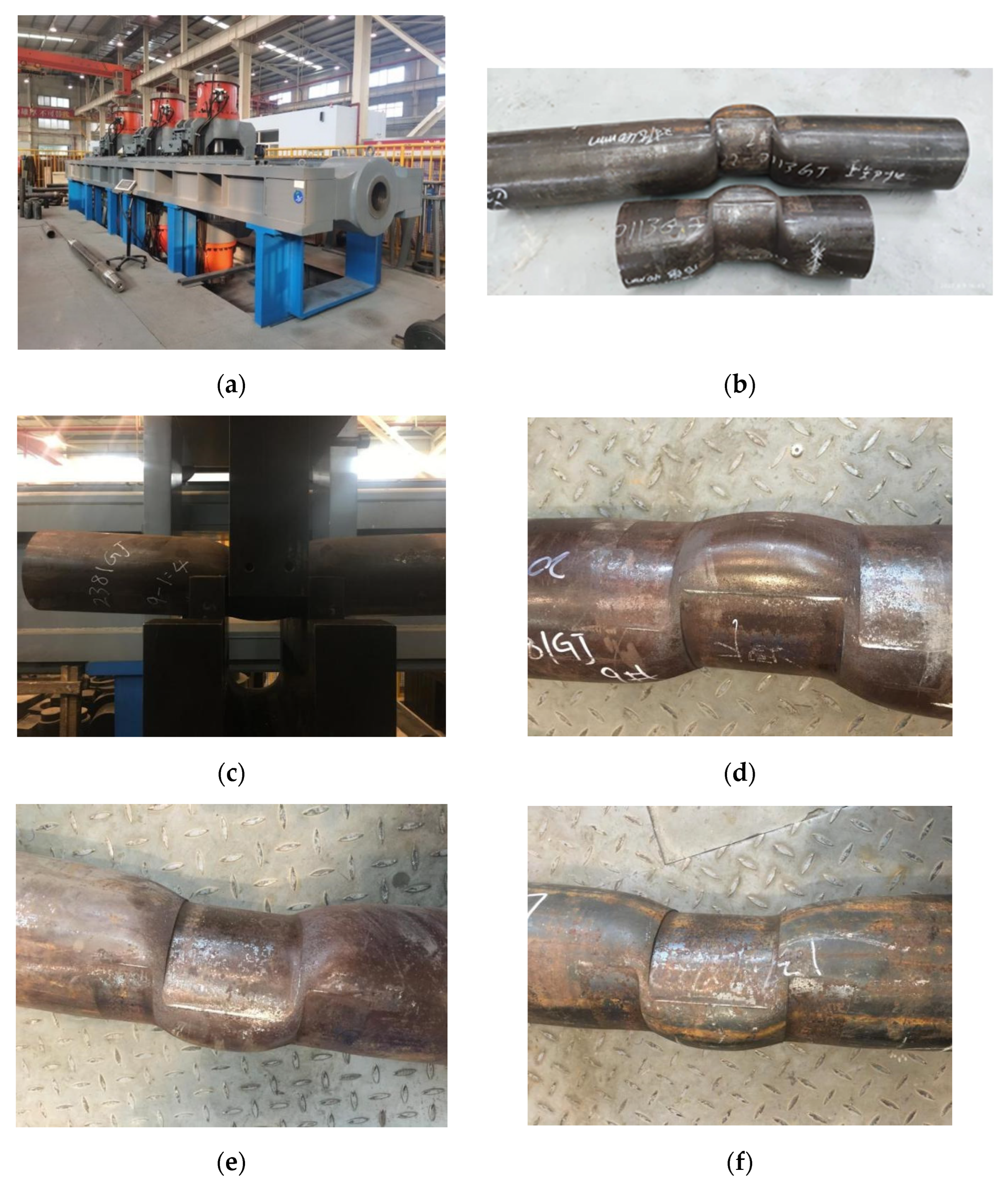
φ139.7 × 12.7 mm) are selected for shear tests. Two sections of 400 mm-long 110 ksi casing numbered #1 and #2 and one section of 400 mm-long 125 ksi casing are intercepted, and the “unconventional oil and gas well casing string simulation test system” is used for shear test, as shown in
Figure 3a. Here, the influence of the pipe ends and the influence zone at the shear deformation need to be considered. Through the comparison of the shear deformation of 800 mm- and 400 mm-long casings (
Figure 3b), it is found that the outer diameter of the two casings after deformation is the same, so the shear force influence area is almost the same. From an economic point of view, 400 mm-long casing is selected. The number of tests in each group with the same parameters is three to ensure the repeatability of the tests.
An ultrasonic thickness gauge is used to measure the wall thickness of four points evenly distributed in the ring of the cross-section, and the diameter in the pressure direction and vertical direction at one half position of the pipe body is measured using vernier calipers. During the test, shearing is 15 mm and the shear load is recorded. The morphology of the casing is shown in
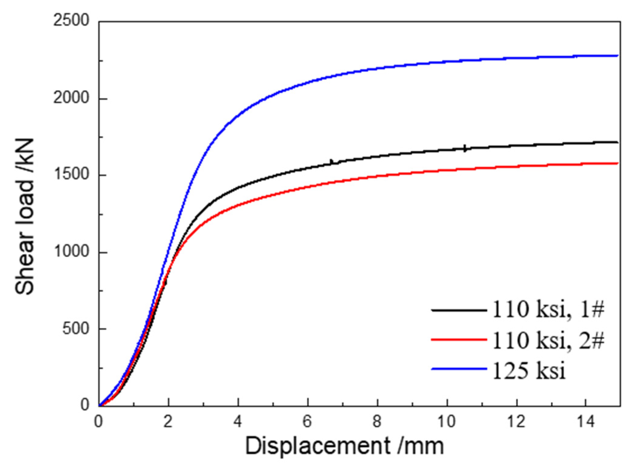
Figure 3c–f, and the relationship between shear load and shear displacement is shown in
Figure 4.
From the above test results, it can be seen that the morphology of casing changes under shear force before and after shear test. The shear load increases with the increase of shear displacement. When the counter-shear is 15 mm, the shear load of 110 ksi casing is 1600 KN and that of 125 ksi casing is 2280 KN.
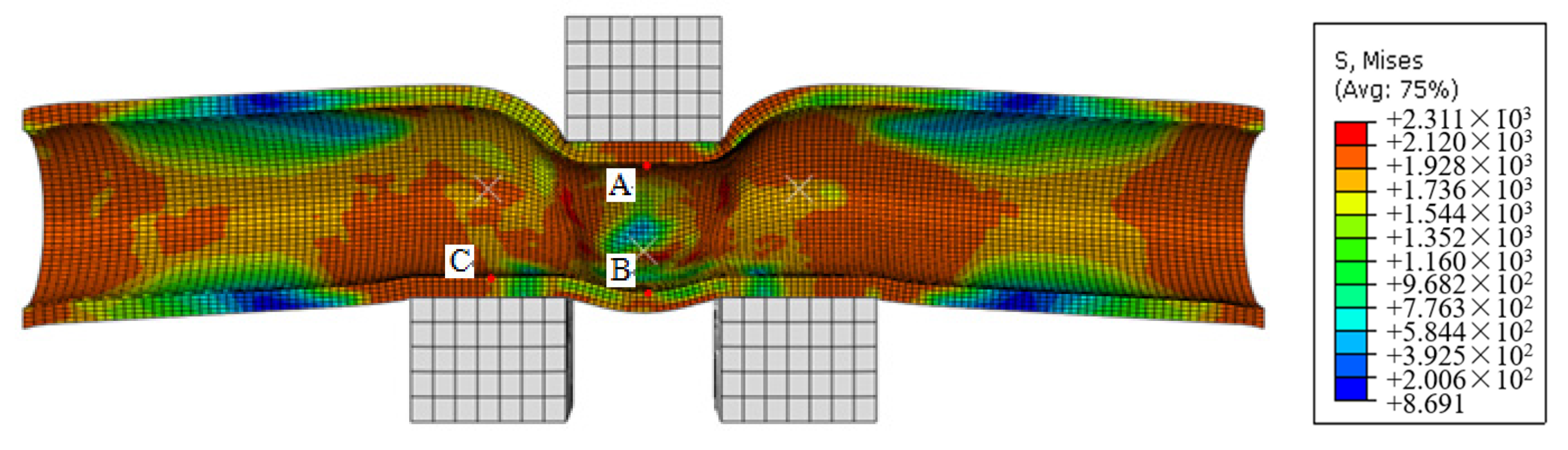
Based on ABAQUS 6.11 software, sourced from CNPC Tubular Goods Research Institute, Xi’an, China, 125 ksi (
φ139.7 × 12.7 mm) casing shear deformation is conducted by finite-element simulation. We take the well axis as the center, and take the 1200 mm-long casing structure as the calculation model. Due to the symmetry of the model, we take one half of the whole model as the calculation model in this paper. As shown in
Figure 5, the outer diameter of the casing is 139.7 mm, and the wall thickness is 12.7 mm. The two ends of the casing and cement sheath are fully restrained, and the side is symmetrically restrained. The friction coefficient between the casing and cement is 0.2, and hexahedral grids are used. The Von Mises yielding criterion and isotropic hardening law are adopted.
The equivalent stress distribution of the pipe body after shearing for 20 mm is shown in
Figure 5. Under non-uniform load, the equivalent stress distribution of the casing tends to be concentrated, and the maximum equivalent stress appears on the inner wall of the casing. Here, the minimum drift diameter is calculated, i.e., the distance AB from the uppermost end of the upper shear fixture to the lowest end, minus the transverse distance BC from the lowest end of the upper shear fixture to the uppermost end of the lower shear fixture. The minimum path is 80.51 mm and the deformation is 33.79 mm.
4.2. Bearing Characteristics of Cement Sheath-Casing under Shear Load Condition
Andrade and Sangesland [
17] pointed out that a cement sheath has a direct impact on the stress load of casing. We select 110 ksi (
φ139.7 × 10.54) and 125 ksi (
φ139.7 × 12.7) casings to conduct cement sheath shear tests. Three sections of 400 mm-long 110 ksi casing numbered #1, #2, and #3 and one section of 400 mm-long 125 ksi casing are sheared for 15 mm and then the appearance and shear loads of the tested casing are analyzed.
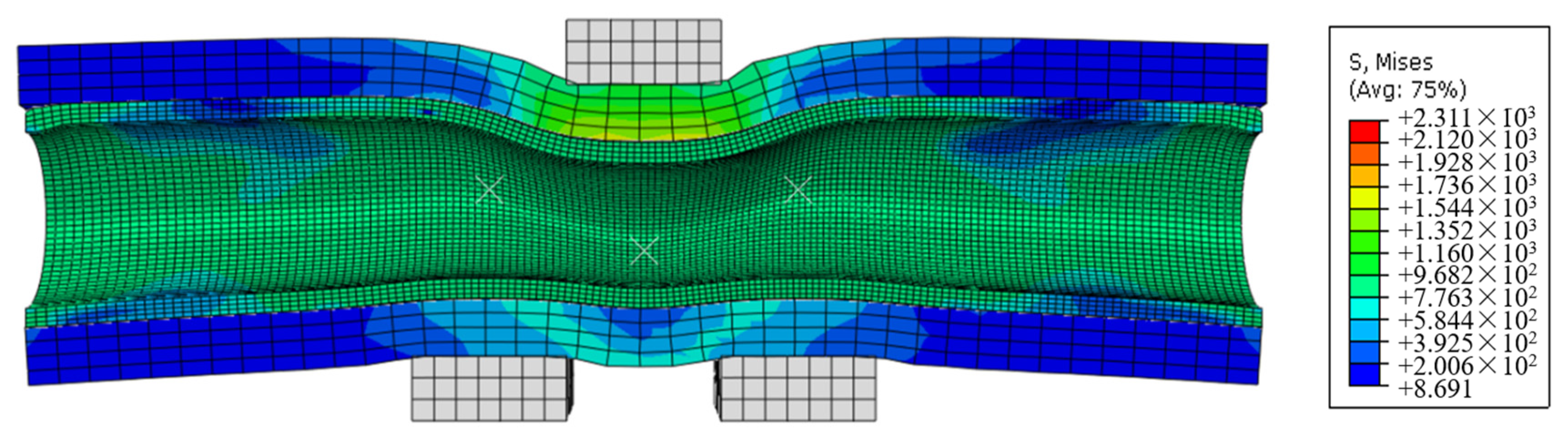
The minimum outer diameter and outer diameter deformation value of the pipe body before and after the tests are shown in
Figure 6. The finite-element numerical simulation data are shown in
Figure 7. Both ends of the casing and cement are fixed, and the friction coefficient between casing and cement is 0.2. Compared with the shear of the pipe body, the equivalent stress after adding a cement sheath is significantly reduced, and the minimum drift diameter calculated by the same method is 82.08 mm. Compared with the shear minimum drift diameter of the pure pipe body of 80.51 mm, the drift diameter is increased by 1.57 mm, and the deformation of the minimum drift diameter is reduced by 1.95%.
According to the analysis of test results, the outer diameter of 110 ksi (
φ139.7 × 10.54) and 125 ksi (
φ139.7 × 12.7) casings become smaller due to the shear force. Through measurement, it is found that the minimum outer diameter of the 110 ksi casing after shearing is 124.16 mm, the deformation value is 16.83 mm, and the maximum deformation is 11.94%; the minimum outer diameter of 125 ksi casing after shearing is 130.94 mm, the deformation value is 9.97 mm, and the deformation is 7.08%. Under the 30 mm shear displacement condition, the deformation of 110 ksi casing is 4.86% larger than that of 125 ksi casing. The morphology of casing after shear test is shown in
Figure 8, and the relationship between shear load and shear displacement is shown in
Figure 9.
From the above test results, it can be seen that the casing morphology changes under the shear force before and after shear test, and the casing deformation after the shear test is smaller than that of the pure pipe body. The shear load increases with the increase of shear displacement. When the counter-shear is 15 mm, the shear load of 110 ksi cement-sheath casing is 1520 KN and that of 125 ksi casing is 1750 KN. Compared with the pipe shear load, under the action of cement sheath and the same shear displacement, the shear load borne by 110 ksi casing decreases by about 5%, and that of 125 ksi casing decreases by 23%.
4.3. Bearing Characteristics of Pure Casing under Non-Uniform Extrusion Condition
110 ksi (
φ139.7 × 10.54 mm) and 125 ksi (
φ139.7 × 12.7 mm) casings are selected for non-uniform external extrusion tests. Two sections of 800 mm-long 110 ksi casing numbered #1 and #2 and one section of 800 mm-long 125 ksi casing are intercepted, and the “unconventional oil and gas well casing string simulation test system” is used for the non-uniform external extrusion test. The counter extrusion displacement is 20 mm and then the appearance, size and deformation are analyzed. We measure the outer diameter and wall thickness of the casing before the test, and measure the minimum outer diameter of the casing after deformation after the extrusion test. The measurement results are shown in
Table 1.
According to the test results, the outer diameters of 110 ksi (φ139.7 × 10.54 mm) and 125 ksi (φ139.7 × 12.7 mm) casings have become smaller. It is found that the minimum outer diameter of 110 ksi casing is 109.18 mm and the maximum deformation is 22.40%, and those of 125 ksi is 107.96 mm and 23.17%.
The casing shape after the extrusion test is shown in
Figure 10, and the relationship between the extrusion load and displacement is shown in
Figure 11. It can be seen that the casing morphology changes under external extrusion force. The extrusion load increases with the increase of displacement. When the counter extrusion is 20 mm, the extrusion load of the 110 ksi casing is 1156 KN and that of the 125 ksi casing is 2024 KN.
4.4. Bearing Characteristics of Cement-Sheath Casing under Non-Uniform Extrusion Condition
After extrusion deformation of 20 mm, the outer diameters of 110 ksi (φ139.7 × 10.54 mm) and 125 ksi (φ139.7 × 12.7 mm) casings become smaller. The minimum outer diameter of 110 ksi casing is 118.6 mm and the maximum deformation is 15.65%, and those of 125 ksi is 124.1 mm and 11.7%. Compared with the pure pipe test, it is found that the deformation value is reduced, indicating that the cement sheath has a certain protective effect on the casing. The finite-element numerical simulation data are studied. Compared with the external extrusion of the pipe, the equivalent stress after adding cement sheath is significantly reduced, and the minimum drift diameter calculated by the same method is 78.21 mm. Compared with 79.28 mm of the pure pipe, the diameter is increased by 1.07 mm, and the deformation of the minimum drift diameter is reduced by 1.35%.
The casing morphology after the extrusion test is shown in
Figure 12, and the relationship between the extrusion load and displacement is shown in
Figure 13. It can be seen that the cement sheath is damaged, and cracks appear locally under the extrusion force. The extrusion load increases with the increase of displacement. When the counter extrusion is 15 mm, the extrusion load of 110 ksi casing is 3825 KN and that of 125 ksi casing is 4404 KN. Compared with the pure pipe extrusion load, the extrusion load of 110 ksi casing increases by about 230%, and that of 125 ksi casing increases by about 117%.
In conclusion, non-uniform extrusion and shear will cause changes to casing morphology. Under the conditions of extrusion and shear with the same displacement, the diameter deformation of casing protected by cement sheath is smaller, and the minimum drift diameter increase of 125 ksi casing is 1.35% and 1.95%, respectively, indicating that elastic cement sheath has a certain protective effect on casing, but the effect is small. Under the action of a cement sheath, with the same extrusion displacement, the extrusion load of 110 ksi casing increases by about 230%, and that of 125 ksi casing increases by about 117%. At the same shear displacement, the shear load of 110 ksi casing decreases by about 5%, and that of 125 ksi casing decreases by 23%.
Under the condition of 30 mm shear displacement of cement-sheath casing, the inner diameter of 110 ksi casing after deformation is 0.89 mm smaller than that of 125 ksi casing after deformation. Under the conditions of external extrusion load with 40 mm displacement, the inner diameter of 110 ksi casing after deformation is 1.28 mm larger than that of 125 ksi casing after deformation, indicating that the cement sheath has a certain protective effect on the casing.
4.5. Influence of Thickness and Elastic Modulus of Elastic Cement Slurry
The influence of thickness and elastic modulus of cement slurry on casing deformation is studied. As shown in
Figure 14, it is found that with the increase of cement slurry thickness, the deformation of casing gradually decreases. The minimum drift diameter increases, and the absorption of formation slip increases less than 3 mm. When the elastic modulus of cement slurry increases, the deformation of casing gradually increases, the minimum drift diameter decreases, and the formation absorption increases by less than 5 mm. Within the range of the simulation parameters, the deformation of the casing is more sensitive to the elastic modulus than the thickness of the cement slurry, and when the elastic modulus is less than or equal to 2 GPa, the casing deformation is greatly reduced and the upper end of pipe body is hardly deformed, as described by Yu et al. [
18].
Due to the complex engineering geological environment, the downhole casing is subjected to various deformation modes such as shear and extrusion under the action of geological strata. Based on the finite-element simulation analysis, the deformation law of cement-sheath casing under the action of shear, single shear and external extrusion is studied, as shown in
Figure 15. Under the action of shear, the deformation of cement-sheath casing decreases and the minimum drift diameter increases by 1.45 mm. It shows that the elastic cement sheath has a certain protective effect on the deformation of casing, but a limited ability to absorb deformation.
Considering the stress concentration at the edges and corners of dies when pure casing is sheared, this paper studies the minimum drift diameter of casing when the die is chamfered (R5), which is reduced by 0.29 mm compared with that without chamfering, indicating that the structure of the die slightly improves the stress uniformity in the cross-section direction of the casing. The upper and lower shear clamps are pressed for 20 mm. Compared with double shear, the deformation in single shear deformation mode is slightly reduced, and the minimum drift diameter increases by 1.87 mm. Under the action of external extrusion, compared with the shear deformation, the deformation increases significantly under the same counter pressure displacement, and the minimum diameter decreases by 2.8 mm compared with the shear deformation.
5. Non-Uniform Bearing Characteristics of Casing in a Modified Cement Slurry System
Due to the limited deformation absorption capacity of elastic cement slurry, as described by Han et al. [
19], a new concept of hollow modification and plasticization of cement sheath is proposed in this paper, which realizes the controllable compression deformation of a high-strength cement sheath, and greatly reduces the casing deformation. A new method of coordinated deformation control of the whole wellbore is established here.
5.1. Simulation Analysis of Crushing Morphology of Modified Cement Slurry
Since the casing deformation mechanism of shale gas horizontal wells is displacement control, and the wellbore system is a closed space, the existing cement slurry system cannot provide space to absorb deformation and the displacement cannot be released. The effect of reducing the elastic cement modulus is not good, and is not easy to realize in engineering. Due to the randomness of the position and size of casing deformation, both the inclined section and horizontal section need prevention and control. Therefore, hollowing of cement sheath can absorb the formation slip based on ensuring the integrity of the wellbore sealing and strength.
Using PFC software, the discrete-element model of modified cement slurry is established, and the crushing forms of cement slurry with formation slip of 5 mm, 10 mm, 15 mm and 20 mm are studied, as shown in
Figure 16. The elastic modulus of the modified cement slurry is 2 GPa, the Poisson’s ratio is 0.25, and the compressive strength is 18 MPa. When the local layer slides down 5 mm perpendicular to the horizontal casing, all high-strength hollow beads have been deformed to varying degrees, and most of the high-strength hollow beads without elastic–plastic deformation fracture show irregular circular shapes such as ellipses. The broken high-strength hollow beads have lost the original supporting role, making room for stratum slip. When the local layer slides to 10 mm, more high-strength hollow beads are broken and further compacted. When the local layer slides to 15 mm, the high-strength hollow beads at the end are basically broken and compacted. When the local layer slides by 20 mm, the cement sheath doped with high-strength hollow beads is completely compacted.
Figure 17 is the stress curve of a high-strength hollow bead cement sheath doped with different contents transmitting to the casing. The addition of high-strength hollow beads can reduce the stress transmitted to the casing. When the content of high-strength hollow beads is 0, the stress transmitted to the casing is 98 MPa. When the mixing content is 10%, the maximum stress transmitted to the casing is 66 MPa. When the mixing content is 20% and 30%, the maximum stress transmitted to the casing is 63 MPa and 61 MPa, respectively. With the increase of high-strength hollow bead content, the load on the casing becomes smaller, which can slow down the casing deformation and protect the casing. Furthermore, doping high-strength hollow beads reduces the strength and stiffness of the cement sheath, and the crushing and compaction of high-strength hollow beads frees up the sliding buffer space of the formation.
5.2. Casing Deformation Law with the Modified Cement Slurry
When the formation slides actively, there is cementation between the cement sheath and formation. As the formation has limited slip, the high-strength casing can no longer resist deformation. Using modified cement slurry, the casing deformation can be transferred through the crushing of hollow glass beads. The modified cement sheath wall thickness is set as 38.1 mm. The changes in casing inner diameter under different cementing mud (proportion of high-strength hollow beads) and casing specifications are studied under the condition of 40 mm formation slip. The relationship between formation slip absorption and cement slurry ratio is determined.
Casings of 125 ksi (
φ127.0 × 11.1 mm, #1~#5) and 125 ksi (
φ139.7 × 12.7 mm, #6~#10) are selected for non-uniform external extrusion tests. Among them, #1 and #6 are elastic cement slurry, #2 and #7 are cement slurry with 10% high-strength hollow beads, #3, #4, #8, #9 are cement slurry with 20% high-strength hollow beads, and #5 and #10 are cement slurry with 25% high-strength hollow beads. High-strength hollow beads have good compatibility with cement slurry. We analyze the minimum outer diameter and deformation value of the casing after 20 mm extrusion, and results are shown in
Figure 18. It can be seen that the deformation value increases with the increase of casing outer diameter and wall thickness. Before the casing plastic deformation, the cement sheath is partially broken and significantly compacted, which can absorb part of the stratum displacement. After the cement sheath is compacted, the casing begins to undergo plastic deformation, and its deformation is significantly lower than that before the cement sheath modification, as shown in
Figure 19. The casing deformation can be controlled by adjusting the proportion of cement sheath hollow particles, i.e., the higher the particle content, the smaller the casing deformation. The main reason is that the hollow beads are broken, absorbing part of the loading displacement, reducing the casing deformation and greatly protecting the casing deformation, to realize the active control of the effective drift diameter of casing, and meet the diameter required for engineering fracturing operation.
Under shear and extrusion conditions, the casing deformation transfer phenomenon is obvious under the action of modified cement sheath. The relationship between the inner drift diameter of casing and the mass ratio of hollow particles is shown in
Figure 20. The local formation slip is 40 mm, for 125 ksi (
φ139.7 × 12.7 mm) casing, when the mass ratio of hollow particles is 20%. Compared with the elastic cement without addition, the deformation absorbed under shear and extrusion conditions are 17.5 mm and 12.3 mm, respectively, indicating that the modified cement slurry has an obvious effect on absorbing the formation slip, which can realize a large deformation of cement and small deformation of casing. The dotted box is the optimization window through which 99 bridge plugs can pass, which provides guidance for casing transformer control of the cement-sheath casing system. A casing of 125 ksi
φ139.7 × 12.7 mm and a conventional hollow particle system can absorb less than 27 mm formation slip in total.
Under the conditions of formation slip, when the ratio of hollow particles and cement slurry is 1:4, the casing deformation transfer phenomenon is obvious. At the initial stage of formation slip (about 10 mm), the force and displacement transmitted to the casing are small, and the casing is not deformed, i.e., the casing inner diameter is not reduced, is considered to be the casing elastic deformation stage, and no obvious plastic deformation occurs. When the formation slip is large, the preventing casing deformation ability of 110 ksi and thick wall casing is weakened, as shown in
Figure 21.
With the modified cement slurry, good results have been obtained in Weiyuan, Changning, Luzhou and other blocks. At present, there is also a well that is not well cemented, and there is no casing change during fracturing, which also proves that the gap of cement slurry can improve the cementing quality and achieve the purpose of casing change prevention and control.
In future research work, especially for the blocks with serious deformation, further prevention and control measures should be proposed based on the comprehensive consideration of casing running mode, borehole expansion, ductile hollow particles cement slurry and complex fracturing conditions.


