
Study on Heat Transfer Process between High-Temperature Slag Particles and Scrap in Drum Based on DEM Method

School of Energy and Environmental Engineering, University of Science and Technology Beijing, Beijing 100083, China
*
Author to whom correspondence should be addressed.
Processes 2024, 12(4), 815; https://doi.org/10.3390/pr12040815
Submission received: 22 March 2024
/
Revised: 12 April 2024
/
Accepted: 16 April 2024
/
Published: 18 April 2024
(This article belongs to the Section Chemical Processes and Systems)
Abstract
:Blast furnace slag, a by-product of the iron and steel production process, contains a significant amount of untapped heat resources. Currently, China is entering a period of rapid growth in scrap production, making efficient scrap utilization a new research focus. One approach to improving scrap utilization is preheating. This study proposes a new method of preheating scrap using high-temperature slag in a drum. The discrete element method is employed for numerical simulation, which involves constructing a three-dimensional model. The study explores three influencing factors: the mass ratio of high-temperature slag to scrap, the shape of the scrap, and the drum rotational speed. The main objective is to investigate the heat transfer situation between the high-temperature slag and the scrap. The results indicate that the optimal heat transfer effect in the drum is achieved when the mass ratio of high-temperature slag to scrap is 2:1, the scrap is spherical in shape, and the drum rotational speed is 12 rpm.
1. Introduction
In recent years, China’s iron and steel industry has experienced rapid development. In 1996, China’s crude steel production exceeded 100 million tons for the first time, continuing to grow thereafter. This substantial output is accompanied by significant energy consumption, making the iron and steel industry a crucial foundational sector of China’s national economy [1]. By 2005, large- and medium-sized enterprises in China were generating 8.44 GJ of waste heat resources for every ton of steel produced, accounting for approximately 37% of the energy consumption per ton of steel. However, the average recovery rate of waste heat resources was only 25.7%, which falls below the international advanced standard of over 50% [2]. Blast furnace slag, a by-product of iron production, contains a substantial amount of heat. Approximately 300 kg of slag is produced per ton of iron, with a discharge temperature of around 1500 °C. The heat energy contained in one ton of slag is approximately 1700 MJ, equivalent to the heating value of 0.058 tons of standard coal [3]. Existing methods for utilizing waste heat from blast furnace slag include rotary cup granulation [4], rotary cylinder granulation [5,6], and air quenching granulation [7,8]. In these methods, waste heat is recovered through heat exchange for further energy utilization. However, energy dissipation occurs in this process.
It takes about 8–30 years for steel to become scrap steel after use. It is expected that China will gradually enter a rapid growth period of scrap steel production. How to effectively utilize scrap steel has become a new research focus. Preheating scrap steel is one of the important ways to increase the scrap steel ratio. Previous research has explored methods of preheating scrap steel, including hot flue gas preheating [9], barrel preheating [10], industrial electric arc furnace burner preheating [11,12], and metal casting preheating [13].
Based on the above facts, it is necessary to explore a method that can directly use the heat of high-temperature slag to preheat scrap steel. This article refers to the working principle of a roller slag cooler for research. Regarding the roller slag cooler, previous studies have been conducted on the heat transfer mechanism inside the roller [14], particle diffusion and collision [15], and experimental heat transfer of particles [16].
This article constructs a three-dimensional model and proposes a new preheating method for scrap steel based on the drum method for preheating high-temperature slag. The heat transfer process of high-temperature slag and scrap steel in the drum is simulated, and the numerical simulation is carried out based on the discrete element method. Three different influencing factors, including the mass ratio of high-temperature slag to scrap steel, the shape of scrap steel, and the rotational speed of the drum, are discussed. The purpose is to explore the heat transfer situation of the drum method for processing high-temperature slag and scrap steel, to investigate the temperature distribution and heat transfer efficiency, and to provide corresponding theoretical guidance for a new method of preheating scrap steel in the future.
2. Model Setup
2.1. Physical Model and Parameterization
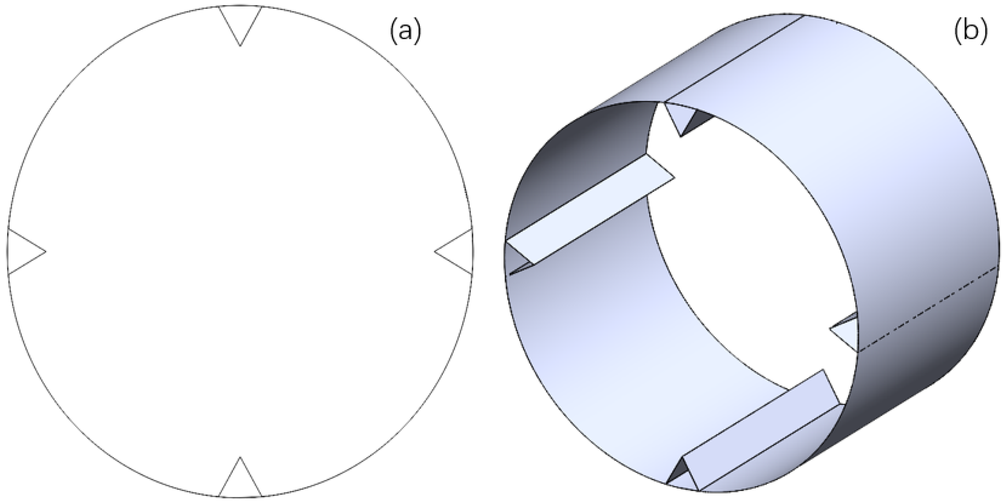
The roller structure used in this article is shown in Figure 1, where Figure 1a is the front view of the roller and Figure 1b is the side view of the roller. The inner diameter of the roller is 240 mm, and the axial length is 320 mm. Inside the roller, four lifting flights are arranged at equal distances, and the distance between the apexes of the lifting flights and the inner wall of the roller is 40 mm.
Table 1 [17] presents the physical parameters of the scrap and high-temperature slag particles utilized in the numerical simulation studies conducted within this research.
According to previous research results, factors affecting the inside of the drum include drum speed, filling ratio, material ratio, material shape, fin shape, etc. [18]. This article selects three influencing factors: slag–steel ratio, scrap shape, and drum speed to conduct research. The corresponding simulation settings are shown in Table 2 below.
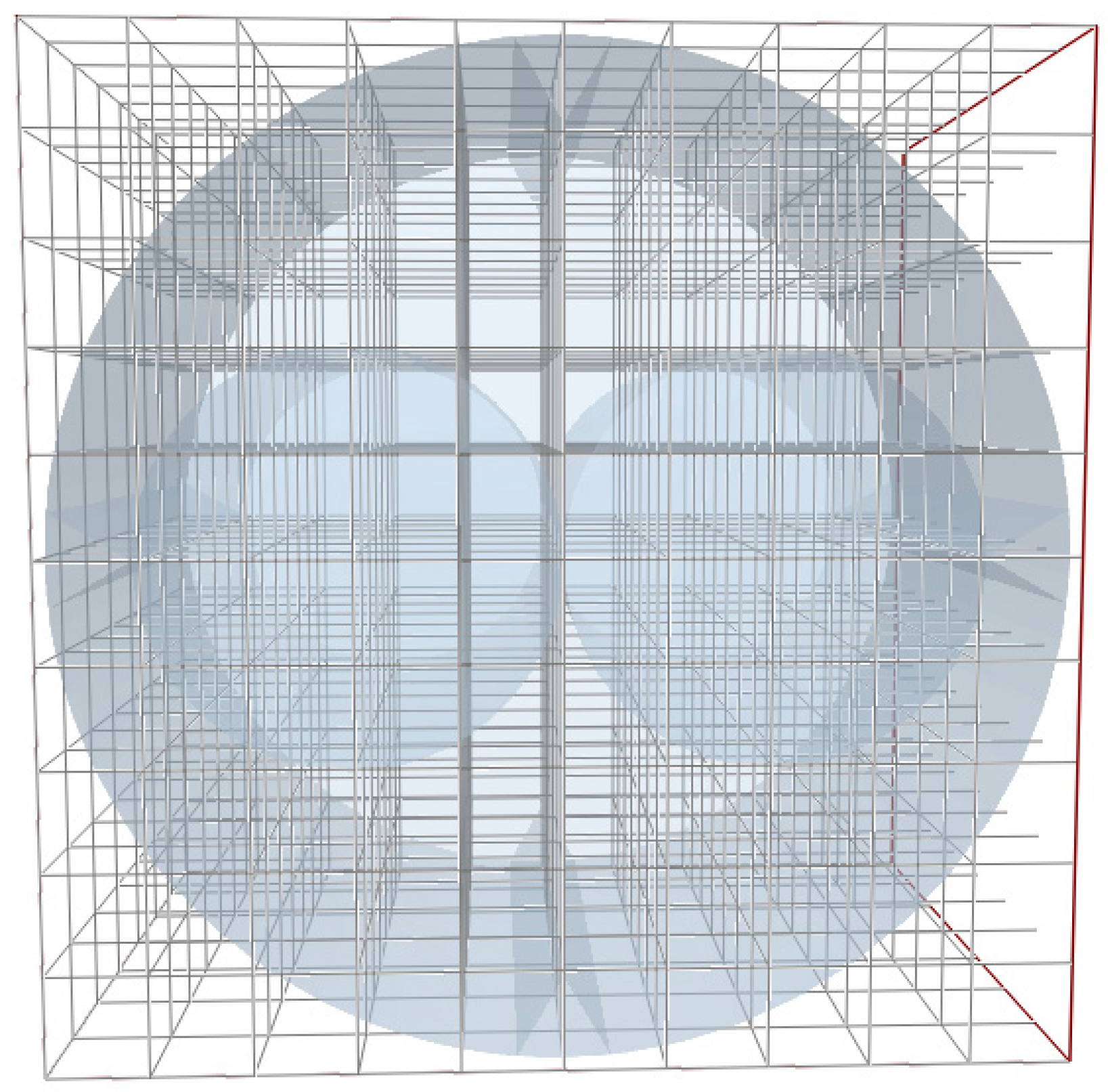
Initially, the high-temperature slag particles are all on the upper side of the scrap steel, showing vertical distribution. The initial temperature of the high-temperature slag particles is set to 1600 K, and the initial temperature of the scrap steel is set to 300 K. According to the numerical simulation theory of the discrete element method [19,20], the Raleigh time step is calculated as 1 × 10⁻⁶ s, and the grid size is set to be 2.5 times the radius of the particles, that is, 2.5 R. The grid settings are shown in Figure 2.
2.2. Numerical Methods
This paper employs the discrete element method (DEM) to conduct numerical simulation analysis. The DEM is a numerical calculation method used primarily to calculate the motion of a large number of particles under given conditions. The discrete element method was proposed by Cundall [21,22,23] in 1972. It is different from the finite element method and the boundary element method in Continuum Mechanics. The basic principle of the discrete element method is Newton’s second law. The DEM is a widely-used numerical method used to solve and analyze the motion and mechanical characteristics of complex discrete systems. The mixing process of high-temperature slag and scrap steel inside the drum can be approximated as a heat and mass transfer process involving a large number of particles. The discrete element method can be applied for computational simulation as it is a typical discrete element system. The domestic software EDEM(2022.1) is used for the simulation calculation. The discrete element method treats each slag particle as an independent entity and simulates the mixing heat transfer between scrap steel and high-temperature slag particles inside the drum. In practical application scenarios, the DEM can reveal the phenomena of mixing and heat transfer inside the drum, providing insights into mixing effectiveness and internal heat transfer. Therefore, the discrete element method has great development prospects in the industrial field [24].
2.2.1. Modeling of Interparticle Contact
This paper adopts the no-slip Hertz–Mindlin contact model [25]. The chosen contact model encompasses damping components for both normal and tangential forces, where the damping coefficient is associated with the coefficient of recovery. The tangential friction adheres to the Coulomb friction law while rolling friction is implemented using a directional constant torque model that is independent of contact. The calculation of the contact forces between particles is performed as outlined below:
Normal elastic stress:
where E* is Equivalent Young’s modulus, Pa; r* is equivalent particle radius, m; is normal overlap when elastic contact occurs between particle 1 and particle 2, m; np1 is unit vector normal to the contact point from the center of the mass of particle 1.
E* can be found using the following equation:
where vp1 and vp2 are Poisson’s ratio for each of particle 1 and particle 2; Ep1 and Ep2 are Young’s modulus of each particle 1 and particle 2, Pa.
r* can be found using the following equation:
where rp1 and rp2—the respective radii of particle 1 and particle 2.
can be found using the following equation:
where app is the center distance between particle 1 and particle 2.
The contact surface between the particles is prototypical and the contact radius is:
2.2.2. Particle Temperature Update Model
To ensure the effective implementation of the inter-particle heat transfer model, it is crucial to incorporate the particle temperature updating model. The temperature updating model must be used in conjunction with the inter-particle heat transfer model to accurately capture the heat transfer effects within the drum. Once the heat transfer between particles is completed, the heat flux is calculated, and the temperature update model is applied to update the temperature of each particle. This equation allows us to obtain the temporal variation of each particle’s temperature.
where m is mass, kg; c is specific heat capacity, J/(kg·K); T is temperature, K; Qheat denotes the sum of convective and conductive heat fluxes.
The utilization of the Hertz–Mindlin contact model in conjunction with the particle temperature update model enables the characterization of the heat transfer effect during the mixing of high-temperature slag and scrap inside the drum.
2.2.3. Modeling of Inter-Particle Heat Transfer
The Watson model [26] was employed to determine the thermal resistance of solid thermal conductivity across the particle contact surface:
where F12,n is the normal contact force between particles, N; k* is particle equivalent thermal conductivity, W/(m·K); r* is particle equivalent radius, m; E*—particle equivalent Young’s modulus, Pa;
2.3. Definition of the Evaluation Function
To visualize the heat exchange occurring between the high-temperature slag and scrap inside the drum, researchers both domestically and internationally have put forward the concepts of average temperature and temperature probability density function [27] (T-PDF) as measures of heat exchange in the system. These methods aim to provide a macroscopic perspective on the overall particle temperature in the system. Specifically, the average mixing temperature is introduced as a means to characterize this temperature, as expressed in the following equation:
where Ti is the temperature of the particle at a given moment in the system, K; N is the total number of particles in the system at a given time.
In the absence of external energy input and output particle energy, the distribution of particle temperatures within the system can be effectively characterized by the probability density function (PDF). The temperature of the particles within the system, denoted as T, always falls within the range of the initially given maximum high-temperature slag temperature, T1, and the temperature of the scrap in the initial drum, T0, specifically T0 < T < T1. Consequently, the dimensionless temperature of the particles, represented as T*, can be determined using the following equation:
The dimensionless temperature T of particles in the system ranges from 0 to 1. When a particle has a higher temperature, its T is larger and closer to 1. On the other hand, when a particle has a lower temperature, its T* is smaller and closer to 0. This calculation enables us to derive the temperature probability density function (T-PDF). At a given time t, the T-PDF in the system can be defined as follows:
where n(T*) is the number of particles in the dimensionless temperature system and N is the sum of the number of particles in the system.
2.4. Validation of the Model
Currently, both domestic and international scholars have utilized the discrete element method (DEM) to conduct simulation and experimental research on the mixing and heat transfer of granular materials in rotary equipment, such as drums [28,29,30,31]. In this study, the simulations were conducted using the same operating conditions as the experiments conducted by Nafsun [31]. The EDEM(2022.1) software was employed to simulate the mixing and heat transfer process between scrap steel and high-temperature slag particles in the drum. All the working conditions were consistent with those described in the referenced article, allowing for the verification of the reliability of the EDEM(2022.1) software and the feasibility of the numerical simulation.
In the study conducted by Nafsun, quartz sand and glass were selected as the experimental materials. The physical parameters of these materials are presented in Table 3. One of the experimental conditions consisted of a 20% filling rate, a drum speed of 6 rpm, a mass ratio of 1:1 between quartz sand particles and glass particles in their initial states, an initial temperature of 130 °C for the quartz sand, and a temperature of 30 °C for the glass particles. The particles were filled in two layers, with hot quartz sand particles being filled first and then room-temperature glass particles. Subsequently, mixing was carried out in the drum under these conditions for a duration of 60 s.
The final simulation results compared with the experimental results are shown in Figure 3.
Through a comparison between the simulation and experimental results, it has been observed that there are discrepancies between the two. However, the calculated error is within 10%, indicating that the numerical simulation results align well with the experimental results. Consequently, the reliability of the simulation results can be affirmed, providing insight into the accuracy of the model. Therefore, the utilization of the discrete element method for studying the mixed heat transfer of scrap and high-temperature slag particles in a drum is deemed effective.
2.5. Verification of Grid Independence
Generally speaking, the finer the grid and the smaller the size, the more accurate the calculation results. However, at the same time, the calculation speed decreases and the amount of data obtained also decreases. For this simulation model of steel scrap mixed with high-temperature slag particles in a drum, five types of grids were used for calculation, with grid sizes set to 0.1 R, 1 R, 2.5 R, 5 R, and 10 R. The set operating conditions were spherical steel scrap, 12 rpm, slag–steel ratio of 2:1, and the average temperature of steel scrap in the drum was calculated at 20 s of drum operation. The results are compared in Table 4. We can see that when the grid size is 2.5 R, the deviation is 0.82%, but the calculation efficiency is greatly improved. Therefore, in this article, all subsequent calculations adopt a grid size of 2.5 R.
3. Results and Discussion
3.1. Influence of Slag–Steel Ratio on Heat Transfer Effect
In this study, the scrap material takes a spherical shape, and the drum rotates at a speed of 12 rpm. To examine the impact of the slag-to-steel ratio on the heat transfer effect between high-temperature slag particles and scrap in the drum, the mass ratios were varied to 1:1, 2:1, and 3:1, respectively.
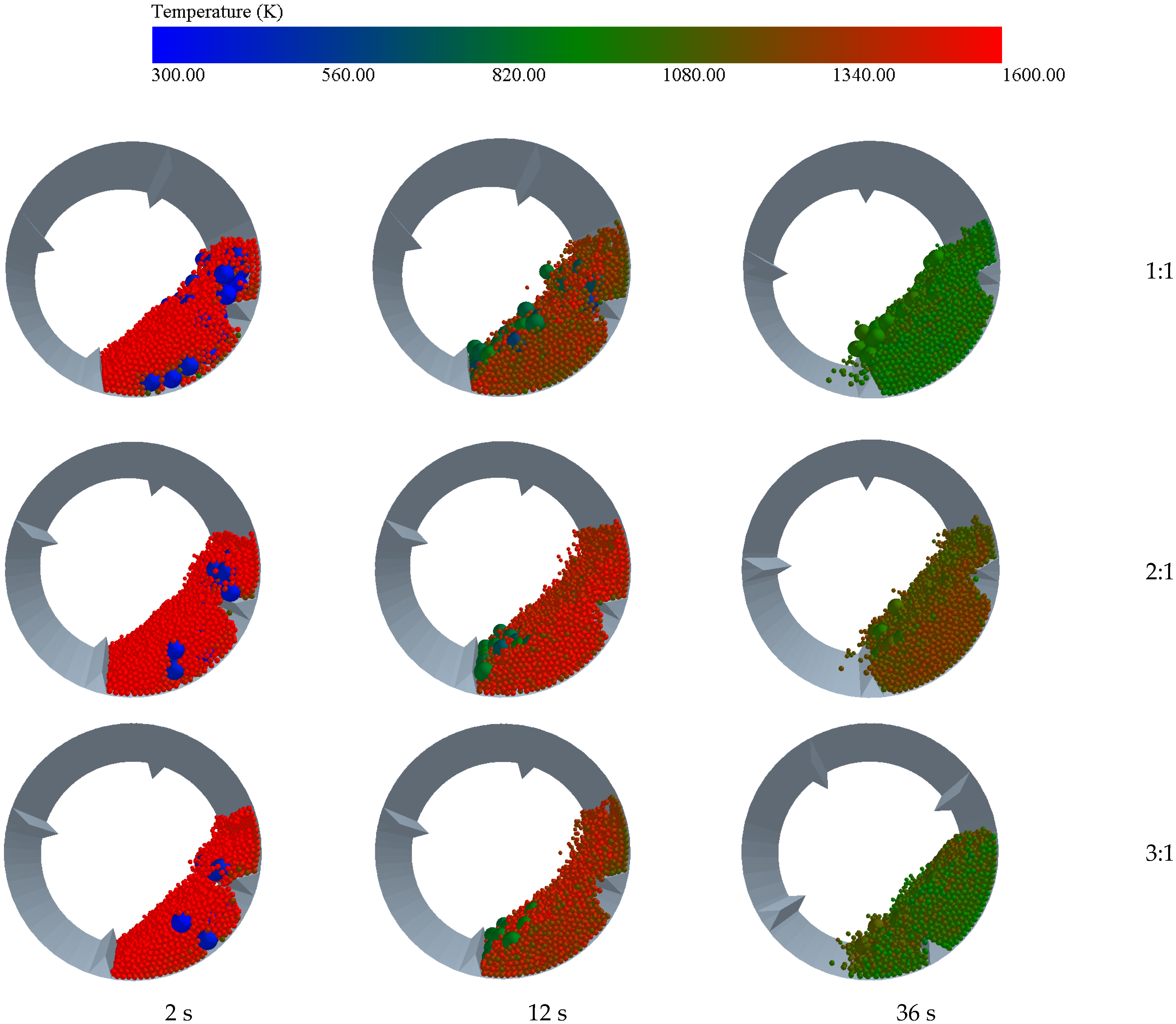
As shown in Figure 4, the heat transfer status nephograms of scrap steel and high-temperature slag particles inside the drum at time points of 2, 12, and 36 s under different slag-steel ratios are presented. It can be observed from the nephograms that a large number of low-temperature particles gather around the high-temperature slag particles near the drum wall, which is referred to as the “high-temperature core area” in previous studies. Most of the high-temperature particles are concentrated in the high-temperature core area inside the drum. Due to the significant temperature difference between the drum wall and the high-temperature particles, during the movement of particles inside the drum, only a small number of low-temperature slag particles diffuse into the high-temperature zone, while the others gather in the low-temperature zone and circulate. The scrap steel heats up while being surrounded by the high-temperature slag particles. When increasing the slag–steel ratio, it can be seen from the nephograms that heat exchange has not yet begun inside the drum at 2 s. When the slag–steel ratio is 1:1, the temperature of the scrap steel inside the drum rises at the slowest rate. However, as the slag–steel ratio increases, the temperature of the scrap steel rises faster.
As depicted in Figure 5, the average temperature of high-temperature slag and scrap in the drum varies over time depending on the slag-to-steel ratio. Observing Figure 5 reveals that, as the drum continuously rotates, heat exchange occurs between the high-temperature slag and scrap, causing the temperature of the scrap to continuously increase. During the initial period, the heat exchange is more intense, resulting in a relatively fast cooling rate for both the scrap and high-temperature slag. This can be attributed to the substantial temperature difference between the high-temperature slag particles and the scrap steel, promoting intense heat exchange between the two. Consequently, the heating rate of the scrap gradually diminishes, as depicted by the slope of the scrap’s average temperature line. The heating curve of the scrap’s average temperature tends to stabilize, indicating a diminishing temperature difference with the high-temperature slag particles. As the slag-to-steel ratio increases from 1:1 to 3:1, the time required for the scrap to warm from 300 K to 1000 K decreases, respectively, from 25 s to 20 s and 19 s. Furthermore, the average temperature drop of the high-temperature slag particles becomes smaller. This can be explained by the increased slag–steel ratio, which results in a higher quantity of high-temperature slag particles in the drum and subsequently more energy. As the same amount of heat is required for the scrap steel to reach the same temperature, the greater quantity of high-temperature slag particles leads to a smaller average temperature drop in the slag. Consequently, the temperature difference between the scrap steel and the slag becomes relatively larger, facilitating a more rapid temperature increase.
Based on the evaluation function definition system proposed in the previous section, the T-PDF plot in the drum was calculated through data processing. Relevant data were selected from the drum at running times t = 1, 6, 12, 18, 24, 30, and 36 s to plot the temperature probability density function. Zoomed-in plots were also processed at dimensionless temperatures T* around 0.05 and 0.2. Figure 6 shows that at t = 1 s, in the initial state, the heat exchange between the scrap steel and high-temperature slag particles has not yet started, resulting in a significant temperature difference between them. The figure also demonstrates that at a dimensionless temperature of 1, the corresponding temperature probability density function reaches approximately 145, while at a dimensionless temperature of approximately 0, a lower probability density function is observed.
The temperature probability density function graph reveals that, as the drum operates, the peak of the temperature probability density function tends towards 0.5. This suggests that the mixing of scrap and high-temperature slag in the drum leads to a gradual convergence of temperatures inside the drum. The waveform shows that at t = 6 s, there is the widest span across the dimensionless temperature range, indicating a higher number of slag particles in the high-temperature section of the drum and a wider temperature distribution. Combined with the analysis of the magnified figure, it can be learned that at this time, the probability density function of the low-temperature region spans a wider range compared to t = 1 s, with little difference in the probability density function. This indicates that during this heat transfer stage, the temperature of the scrap steadily increases as the scrap and high-temperature slag particles undergo intense heat transfer. As time progresses, the temperature probability density function plot becomes narrower across the distance, indicating a decreasing temperature span between the scrap and the high-temperature slag particles in the drum, bringing it closer to the thermal equilibrium state of mixing.
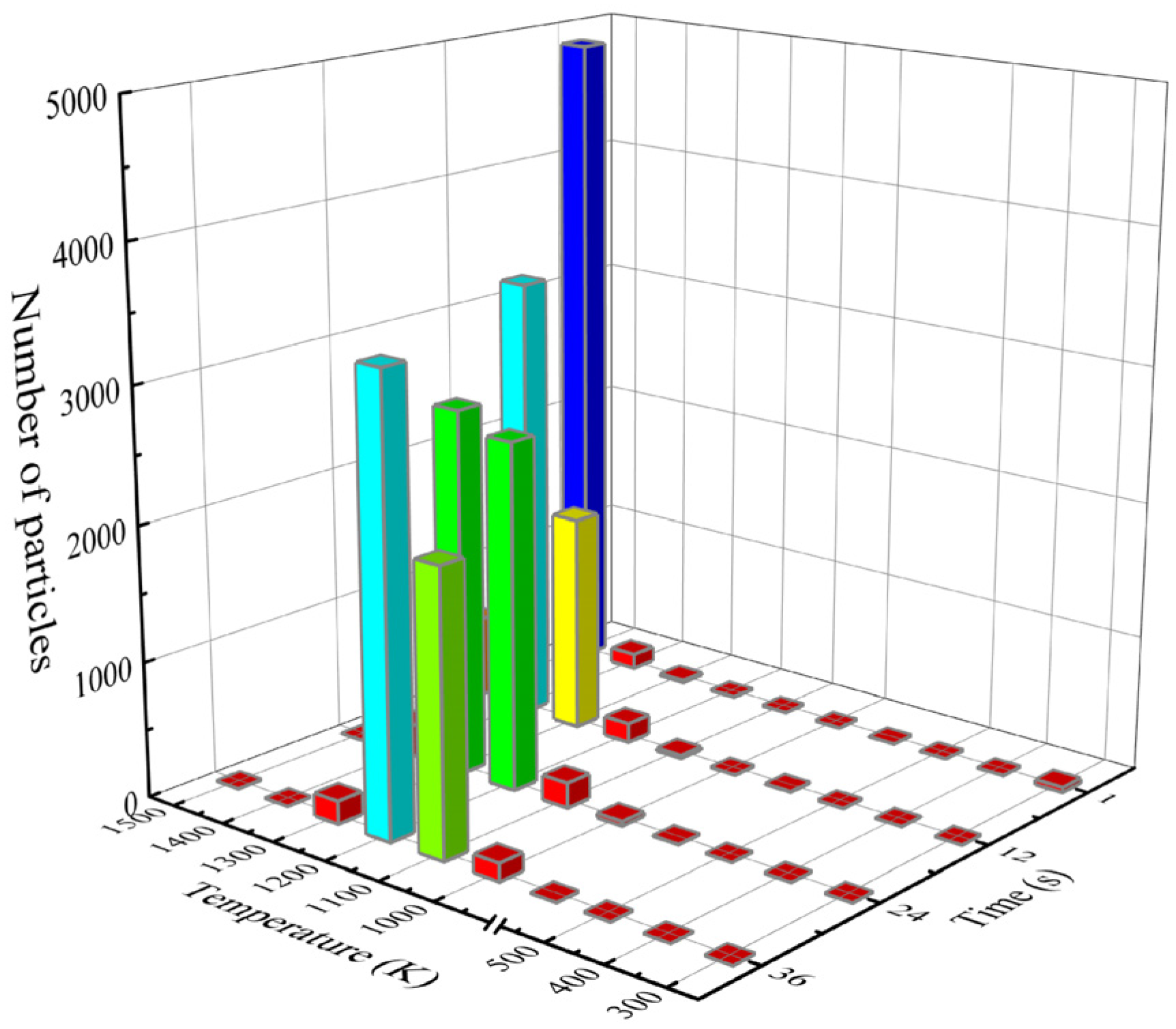
Particles inside the drum were extracted based on time and temperature for a slag–steel ratio of 2:1, and a 3D stacking diagram was plotted (see Figure 7). Figure 7 illustrates that at the initial moment, the number of high-temperature slag particles is highest, while the number of scrap steel particles is relatively low, corresponding to a scrap steel temperature of 300 K. Additionally, due to the heat exchange between the scrap and the higher temperature slag particles in the drum, the particles in the drum tend to center around 1000 K, which is consistent with the results obtained from analyzing the T-PDF diagram in the previous section.
This section examines the impact of the slag-to-steel ratio on the heat transfer and mixing in the drum. A higher slag-to-steel ratio is associated with a higher final temperature of the scrap steel. However, a higher slag-to-steel ratio results in excessive high-temperature slag, which hinders the mixing of substances in the drum. Consequently, when compared, a slag-to-steel ratio of 2:1 exhibits the most favorable effect on increasing the temperature of the scrap steel.
3.2. Effect of Scrap Shape on Heat Transfer Effectiveness
The impact of scrap shape on the heat transfer between scrap and slag in the drum was examined by altering the scrap shape to square, spherical, and tetrahedral configurations while maintaining a slag-to-steel ratio of 2:1 and a drum speed of 12 rpm. This modification was implemented while ensuring that the overall quantity of scrap remained constant and that the individual masses of scrap for each shape were equal. This method was employed to ensure that the total amount of heat required to raise the temperature remained consistent.
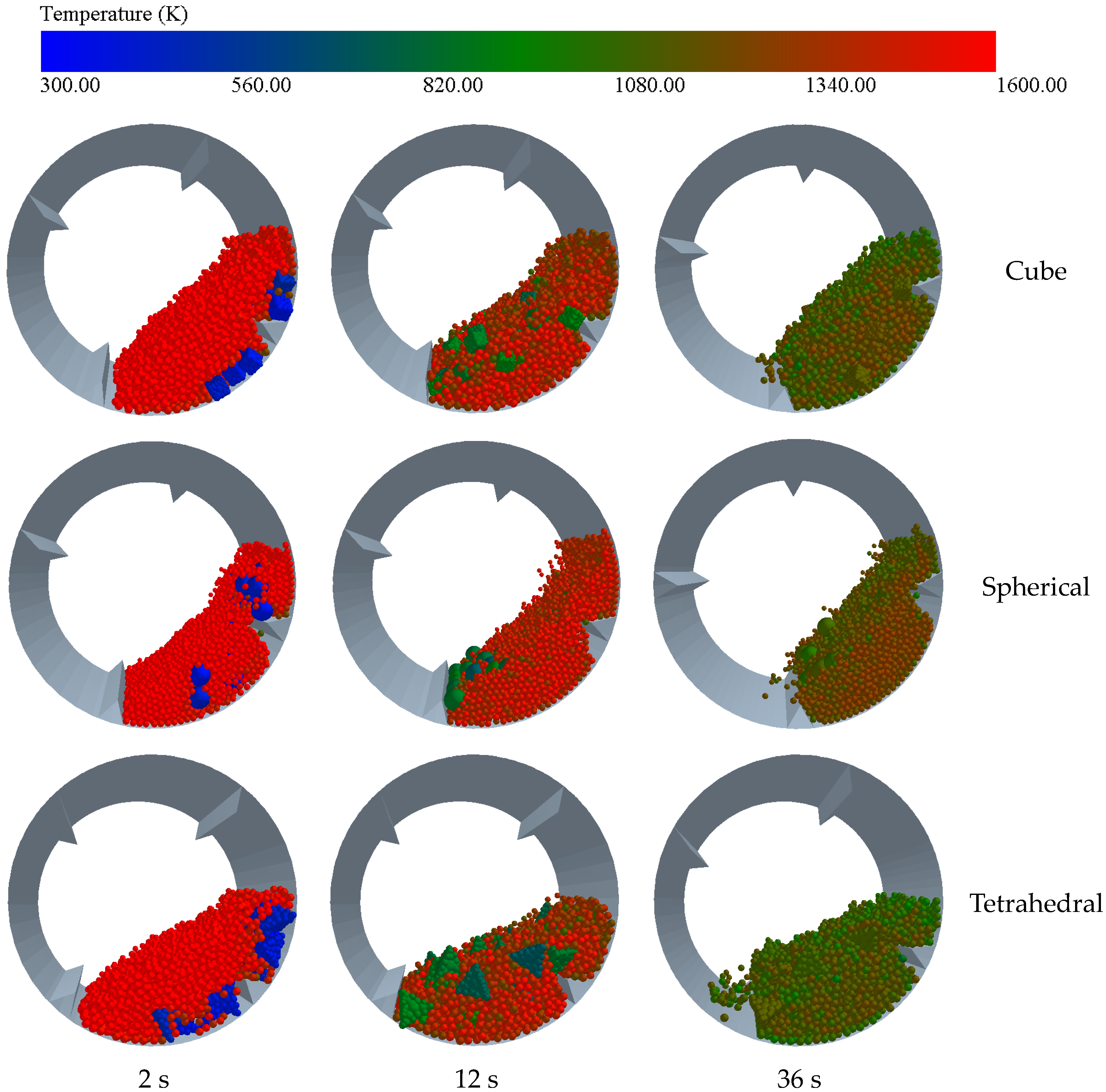
As shown in Figure 8, the temperature distribution cloud map of the heat transfer characteristics between the scrap steel and the high-temperature slag in the drum is used to change the shape of the scrap steel. From the figure, it can be observed that when the shape of the scrap steel is spherical, there is a clear high-temperature accumulation zone, and the high-temperature slag particles near the drum wall have a lower temperature. Compared to spherical scrap steel, the heat transfer of the remaining two types of scrap steel particles has a more concentrated high-temperature slag particle accumulation zone.
As depicted in Figure 9, the average temperature of the high-temperature slag and scrap within the drum varies over time depending on the shape of the scrap. Through analysis of the figure, it becomes evident that the heat exchange process between the high-temperature slag and scrap steel gradually decelerates as time progresses. Initially, when the heat exchange commences, there is a significant temperature difference between the scrap steel and the high-temperature slag particles, resulting in a rapid heat exchange. Observing the average temperature graph, it is apparent that the heating rates for square and spherical scrap are comparable. However, the tetrahedral scrap exhibits a slower rate, which can be determined by comparing the time taken for each shape to reach a temperature of 1000 K. The times for the spherical, square, and tetrahedral shapes are 18 s, 16 s, and 19 s, respectively.
The temperature probability density function (PDF) graphs were generated based on data obtained from Figure 10 for different shapes of scrap steel. Specifically, the selected drum running times were t = 1, 6, 12, 18, 24, 30, and 36 s. In order to provide a more detailed analysis, the dimensionless temperature T* was examined within a range of approximately 0.05 to 0.2, and an enlarged graph was created for that specific region. From the analysis of the figure, it is evident that for the initial moment (t = 1 s), the probability density of high-temperature and low-temperature regions in the drum varies significantly. This indicates a separation between hot and cold regions, with minimal heat exchange occurring. Consequently, the dimensionless temperature exhibits a distribution skewed toward both very high and very low values. Upon observing the probability density function plot, it becomes apparent that at t = 36 s, the distribution for spherical, square-shaped, and tetrahedral-shaped scrap steel differs. The distribution span is narrowest for spherical scrap, with the plot displaying the highest peak. This signifies more uniform temperature mixing and sufficient heat exchange between the scrap and high-temperature slag particles. The figure further demonstrates how the temperature probability density function plots become narrower as heat exchange progresses, indicating a more uniform temperature distribution between the scrap and high-temperature slag particles. Additionally, the peaks of the temperature probability density function plots gradually shift toward the middle, indicating a concentration of particle temperatures as heat exchange proceeds within the drum, without any changes in the substance itself.
This section examines the impact of various scrap shapes on the heat transfer between high-temperature slag and scrap within the drum. When the shape of the scrap is altered, it is observed that the tetrahedral scrap exhibits a slower rate of heating, resulting in less-efficient overall heat transfer compared to the spherical and square shapes. Furthermore, the temperature distribution of the spherical scrap becomes the most concentrated after the same duration, leading to a relatively stable overall temperature.
3.3. Influence of Drum Speed on the Heat Transfer Effect
When considering a spherical shape for the scrap in the drum with a slag–steel ratio of 2:1, the drum speed is adjusted to 8, 12, and 16 rpm, respectively. As shown in Figure 11, the temperature distribution cloud map at different times is changed by changing the rotation speed of the drum. At different times and different rotation speeds of the drum, a large number of low-temperature particles are distributed on the wall surface of the drum, while high-temperature particles are concentrated in the relatively high-temperature gathering area near the middle. It can be seen from the figure that when the rotation speed of the drum is increased, the high-temperature core area becomes smaller, but it becomes larger again as the drum rotates. This is due to the increase in slip between high-temperature slag particles and the drum wall surface during the increase in the rotation speed of the drum, which increases its centrifugal force, thus reducing the possibility of entering the high-temperature core area. However, as the heat transfer process proceeds, the temperature of the substances inside the drum reaches a stable level.
The average temperature of the high-temperature slag and scrap within the drum is then graphed against time, as illustrated in Figure 12. An analysis of the graph reveals that, overall, the heating rate of the scrap gradually decelerates, with the fastest heating occurring initially. This can be attributed to the initial state in which the high-temperature slag and scrap have just initiated the heat transfer process, resulting in the largest temperature difference between the two. As the heat transfer progresses, the rate at which the scrap steel heats up decreases gradually. Comparing the rate of temperature rise for the scrap steel at different speeds, it becomes evident that a drum speed of 8 and 16 rpm yields a relatively slower rate compared to a speed of 12 rpm. This disparity arises from the fact that, at lower rotational speeds, gravity primarily influences the material within the drum, leading to minimal mixing and slower heat transfer. As the drum speed increases, the material within the drum rises due to centrifugal force, clinging to the drum’s walls and hindering effective mixing. Consequently, a drum speed of 12 rpm proves most effective for the mixing of high-temperature slag and scrap within the drum.
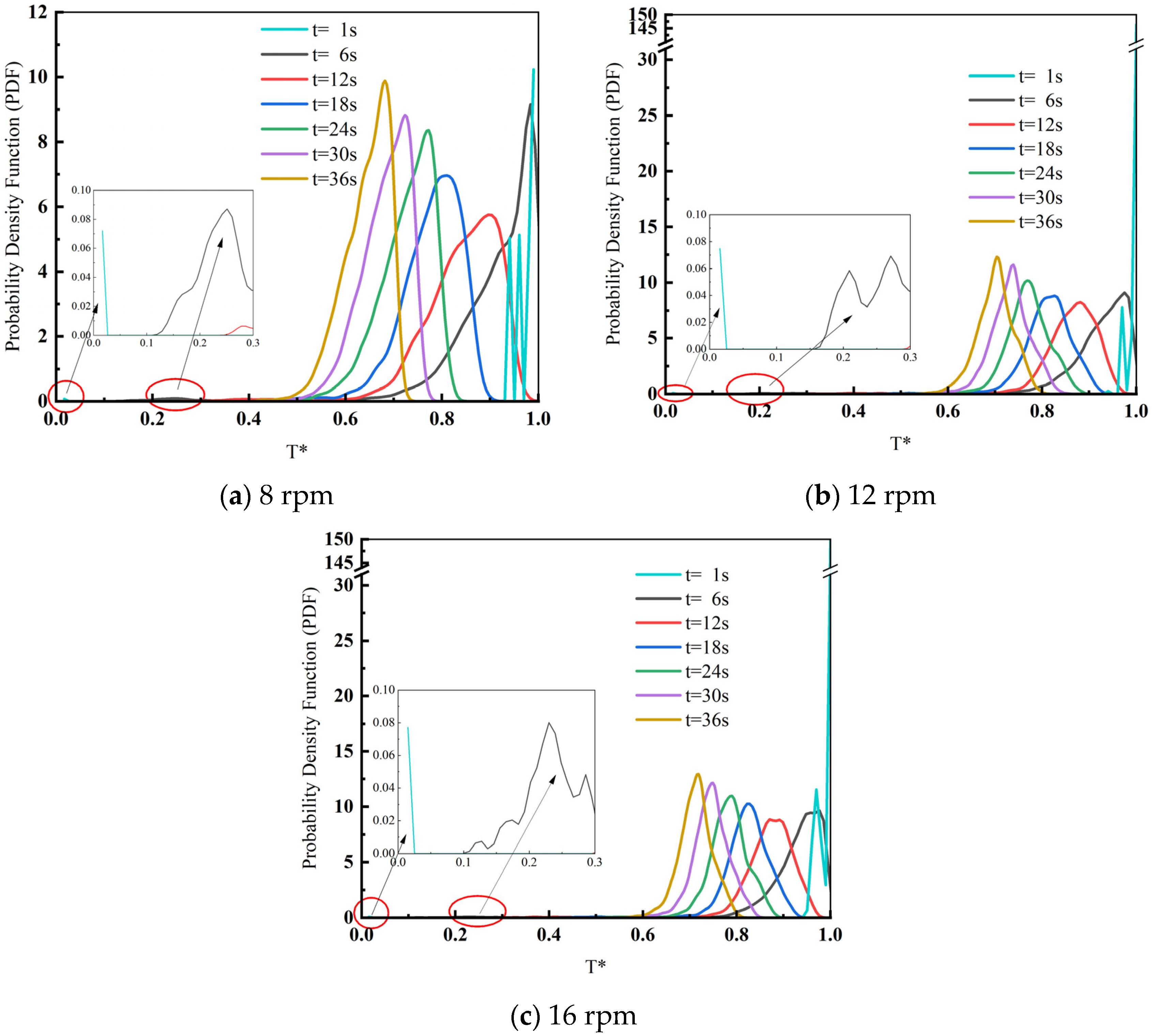
The temperature probability density function (PDF) graph for different drum speeds is shown in Figure 13. From the PDF graph at t = 1 s, it can be observed that the heat exchange between the scrap and high-temperature slag particles has not yet started, as indicated by the concentration of particle dimensionless temperature (T) around 1. Enlarging the graph reveals particles near T = 0, which correspond to the initial state with a ratio of scrap to system content. At this point, the cold scrap is completely separated from the hot, high-temperature slag particles. At t = 6 s, the temperature begins to rise in the dimensionless temperature range of 0.2 to 0.3. This signifies the initiation of heat transfer inside the drum, where heat from the high-temperature slag is mainly transferred to the scrap through thermal conductivity, causing the scrap to warm up. Over time, the graph indicates a gradual increase in the number of particles at intermediate temperatures, while the number of particles at extreme temperatures decreases. Both the minimum and maximum temperature particles exhibit a decreasing trend. At t = 36 s, which corresponds to the highest peak, it can be inferred that the heat transfer between the high-temperature slag particles and scrap steel is more complete. Most of the particles in the drum exhibit uniform heat transfer, concentrated in an average temperature range. When comparing the T-PDF graphs, it can be deduced that a drum speed of 12 rpm results in more adequate heat transfer between the scrap and high-temperature slag, with T* being closer to 0.6. Additionally, the presence of larger wave peaks at this speed indicates more uniform heat transfer. A drum speed of 12 rpm promotes smoother mixing of the high-temperature slag and scrap due to gravitational and centrifugal forces, resulting in intensified heat transfer.
This section discusses the impact of drum speed on heat transfer effectiveness. Analyzing the time required to preheat the scrap to 1000 K reveals that a drum speed of 12 rpm outperforms both high and low speeds. By examining the T-PDF graph, it can be deduced that at the final stage of mixed heat transfer in the drum, the temperature distribution becomes more uniform. In conclusion, considering the influence of gravity and centrifugal force, an optimal drum speed of 12 rpm is identified within the range explored in this paper.
4. Conclusions
Utilizing the discrete element method (DEM) principle, this paper employs EDEM(2022.1) software to investigate the heat transfer process between high-temperature slag particles and scrap within the drum. The study examines three influential factors, namely the slag-to-steel ratio, scrap shape, and drum rotational speed. The obtained research findings provide theoretical guidance for a novel approach to the preheating treatment of scrap and high-temperature slag within the drum. The main conclusions of the study are summarized below:
(1) The heat transfer effectiveness between the high-temperature slag and scrap within the drum varies with different slag-to-steel ratios. A higher slag-to-steel ratio corresponds to a higher final temperature of the scrap. However, an excessively high amount of high-temperature slag due to the increased ratio hinders the mixing of substances within the drum. Based on the previous analysis and discussion, it is evident that the time required to preheat the scrap to 1000 K differs with varying slag-to-steel ratios. Notably, the best temperature rise for the scrap is achieved at a slag-to-steel ratio of 2:1.
(2) When altering the shape of the scrap, a comparison of the time required to preheat the scrap to 1000 K reveals that the tetrahedral scrap exhibits a slower heating rate. Additionally, the overall heat transfer effectiveness of the tetrahedral shape is inferior to that of the spherical and square shapes. Analyzing the T-PDF graph, it is observed that, after the same duration, the temperature distribution of the spherical scrap is the most concentrated, resulting in a relatively stable overall temperature.
(3) The rotational speed of the drum significantly impacts the heat transfer between the scrap and the high-temperature slag. The heat transfer is found to be more efficient at a drum speed of 12 rpm compared to both high and low speeds. This improvement is attributed to the effects of gravity and centrifugal force on the material inside the drum. Hence, a drum speed of 12 rpm can be considered as the optimal speed for maximizing the heat transfer effect.
In summary, this study proposes a new process to treat high-temperature slag at the theoretical level, and obtains the optimal operating conditions for the treatment of high-temperature slag and scrap steel using the roller method. The spherical scrap steel, the roller speed of 12 rpm, and the slag–steel ratio of 2:1 are obtained. The research results can be used to theoretically guide a new type of preheating process for scrap steel and high-temperature slag using a drum, which leads to the better use of waste heat resources, further resource conservation, and a reduction in energy consumption. In future research, we can conduct more operational parameter ranges, consider more complex operating conditions, and adapt to the actual operating conditions of different steel companies.
Author Contributions
Methodology, F.S.; software, F.S.; validation, F.S. and B.L.; formal analysis, Q.Z.; investigation, G.F. and Q.Z.; resources, C.L. and B.L.; data curation, G.F. and C.L.; writing—original draft, G.F.; writing—review and editing, G.F.; visualization, B.L. All authors have read and agreed to the published version of the manuscript.
Funding
This research received no external funding.
Data Availability Statement
Data are contained within the article.
Conflicts of Interest
The authors declare no conflicts of interest.
References
- Li, K.; Zou, D.; Li, H. Environmental regulation and green technical efficiency: A process-level data envelopment analysis from Chinese iron and steel enterprises. Energy 2023, 277, 127662. [Google Scholar] [CrossRef]
- Inayat, A. Current progress of process integration for waste heat recovery in steel and iron industries. Fuel 2023, 338, 127237. [Google Scholar] [CrossRef]
- Wang, H.; Liu, C.; Xing, H.-W.; Wu, J.-H.; Lin, W.-L.; Li, S.; Ding, G.-H.; Zhang, Y.-Z. High-temperature modification and air-quenching granulation of steel slag. J. Iron Steel Res. Int. 2021, 29, 783–792. [Google Scholar] [CrossRef]
- Pickering, S.; Hay, N.; Roylance, T.; Thomas, G. New process for dry granulation and heat recovery from molten blast-furnace slag. Ironmak. Steelmak. 1985, 12, 14–20. [Google Scholar]
- Xie, D.; Pan, Y.; Flann, R.; Washington, B.; Sanetsis, S.; Donnelley, J.; Norgate, T.; Jahanshahi, S. Heat recovery from slag through dry granulation. In Proceedings of the 1st CSRP Annual Conference, Melbourne, Australia, 5 July 2007; pp. 29–30. [Google Scholar]
- Yoshida, H.; Nara, Y.; Nakatani, G.; Anazi, T.; Sato, H. The technology of slag heat recovery at NKK. In Proceedings of the SEAISI Conference of Energy Utilization in the Iron and Steel Industry, Singapore, 10–13 September 1984. [Google Scholar]
- Tanaka, J.; Kabasawa, M.; Nagae, M.; Ono, M. Fatigue strength and strain behaviour of spot-welded joints in steels for automobiles. Nippon Kokan Tech. Rep. Overseas 1986, 47, 45–51. [Google Scholar]
- Rodd, L.; Koehler, T.; Walker, C.; Voermann, N. Economics of slag heat recovery from ferronickel slags. In Proceedings of the Sustainability for Profit. Conference of Metallurgists (COM2010), Vancouver, BC, Canada, 3–6 October 2010; pp. 3–17. [Google Scholar]
- Arink, T.; Hassan, M.I. Metal scrap preheating using flue gas waste heat. Energy Procedia 2017, 105, 4788–4795. [Google Scholar] [CrossRef]
- Lee, B.; Sohn, I. Review of innovative energy savings technology for the electric arc furnace. JOM 2014, 66, 1581–1594. [Google Scholar] [CrossRef]
- Chen, Y.; Ryan, S.; Silaen, A.K.; Zhou, C.Q. An Investigation into EAF Burner Preheating and Melting Characteristics: CFD Model Development and Experimental Validation. Metall. Mater. Trans. B 2023, 54, 1068–1087. [Google Scholar] [CrossRef]
- Oh, J.; Lee, E.; Noh, D. Development of an oxygen-enhanced combustor for scrap preheating in an electric arc furnace. Appl. Therm. Eng. 2015, 91, 749–758. [Google Scholar] [CrossRef]
- Selvaraj, J.; Varun, V.; Vishwam, V. Waste heat recovery from metal casting and scrap preheating using recovered heat. Procedia Eng. 2014, 97, 267–276. [Google Scholar] [CrossRef]
- Si, X.D.; Lu, J.F.; Wang, W.; Li, J.J. Research on Heat Transfer Model of Cylindrical Slag Cooler. J. Power Eng. 2011, 31, 342–346. [Google Scholar]
- He, Q.Z.; Lai, J.A.; Wang, J.; Liao, B.Q.; Peng, T. Axial Diffusion Motion of Particles in Cylindrical Slag Cooler Based on EDEM-FLUENT Coupling. Sci. Technol. Eng. 2022, 22, 1004–1010. [Google Scholar]
- Zhuang, Y.; Chen, H.P.; Yang, H.P.; Wang, X.H.; Zhang, S.H. One-Dimensional Heat Transfer Simulation of Cylindrical Slag Cooler. J. Power Eng. 2011, 31, 497–501+529. [Google Scholar]
- Feng, Y.; Gao, J.; Feng, D.; Zhang, X. Modeling of the molten blast furnace slag particle deposition on the wall including phase change and heat transfer. Appl. Energy 2019, 248, 288–298. [Google Scholar] [CrossRef]
- Geng, F.; Chai, H.; Ma, L.; Luo, G.; Li, Y.; Yuan, Z. Simulation of dynamic transport of flexible ribbon particles in a rotary dryer. Powder Technol. Int. J. Sci. Technol. Wet Dry Part. Syst. 2016, 297, 115–125. [Google Scholar] [CrossRef]
- Cook, B.K.; Jensen, R.P. Discrete Element Methods: Numerical Modeling of Discontinua; American Society of Civil Engineers: Reston, VA, USA, 2002. [Google Scholar]
- Luding, S. Introduction to discrete element methods: Basic of contact force models and how to perform the micro-macro transition to continuum theory. Eur. J. Environ. Civ. Eng. 2008, 12, 785–826. [Google Scholar] [CrossRef]
- Cundall, P.A. A computer model for simulating progressive, large-scale movement in blocky rock system. In Proceedings of the International Symposium on Rock Mechanics, Nancy, France, 4–6 October 1971; pp. 129–136. [Google Scholar]
- Cundall, P.A. Computer simulations of dense sphere assemblies. Stud. Appl. Mech. 1988, 20, 113–123. [Google Scholar]
- Cundall, P.A.; Strack, O.D. A discrete numerical model for granular assemblies. Géotechnique 1979, 29, 47–65. [Google Scholar] [CrossRef]
- Kruggel-Emden, H.; Wirtz, S.; Simsek, E.; Scherer, V. Modeling of granular flow and combined heat transfer in hoppers by the discrete element method (DEM). J. Press. Vessel. Technol. 2006, 128, 439–444. [Google Scholar] [CrossRef]
- Mindlin, R.D. Compliance of Elastic Bodies in Contact. J. Appl. Mech. 1949, 16, 259–268. [Google Scholar] [CrossRef]
- Vargas, W.L.; McCarthy, J.J. Heat conduction in granular materials. Aiche J. 2001, 47, 1052–1059. [Google Scholar] [CrossRef]
- Gui, N.; Fan, J. Numerical study of heat conduction of granular particles in rotating wavy drums. Int. J. Heat Mass Transf. 2015, 84, 740–751. [Google Scholar] [CrossRef]
- Chand, R.; Muniandy, S.V.; San Wong, C.; Singh, J. Discrete element method study of shear-driven granular segregation in a slowly rotating horizontal drum. Particuology 2017, 32, 89–94. [Google Scholar] [CrossRef]
- Deng, S.; Wen, Z.; Su, F.; Wang, Z.; Lou, G.; Liu, X.; Dou, R. Radial mixing of metallurgical slag particles and steel balls in a horizontally rotating drum: A discussion of particle size distribution and mixing time. Powder Technol. 2020, 378, 441–454. [Google Scholar] [CrossRef]
- Herz, F.; Mitov, I.; Specht, E.; Stanev, R. Experimental study of the contact heat transfer coefficient between the covered wall and solid bed in rotary drums. Chem. Eng. Sci. 2012, 82, 312–318. [Google Scholar] [CrossRef]
- Nafsun, A.; Herz, F.; Specht, E.; Komossa, H.; Wirtz, S.; Scherer, V. Experimental investigation of thermal bed mixing in rotary drums. In Proceedings of the International Conference on Heat Transfer, Fluid Mechanics and Thermodynamics, Skukuza, South Africa, 20–23 July 2015. [Google Scholar]
Figure 1.
Schematic diagram of the drum structure: (a) front view of drum; (b) drum.

Figure 2.
Grid diagram.

Figure 3.
Comparison of simulation results with experimental results.
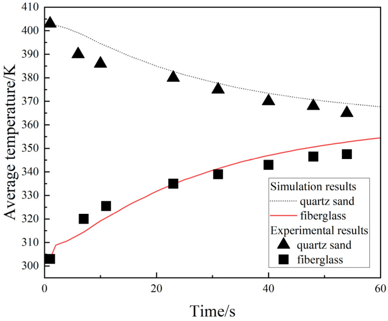
Figure 4.
Particle temperature distribution in the drum with different slag–steel ratios.

Figure 5.
Average temperature of high-temperature slag and scrap in the drum with time when the slag-to-steel ratio varies.
Figure 5.
Average temperature of high-temperature slag and scrap in the drum with time when the slag-to-steel ratio varies.
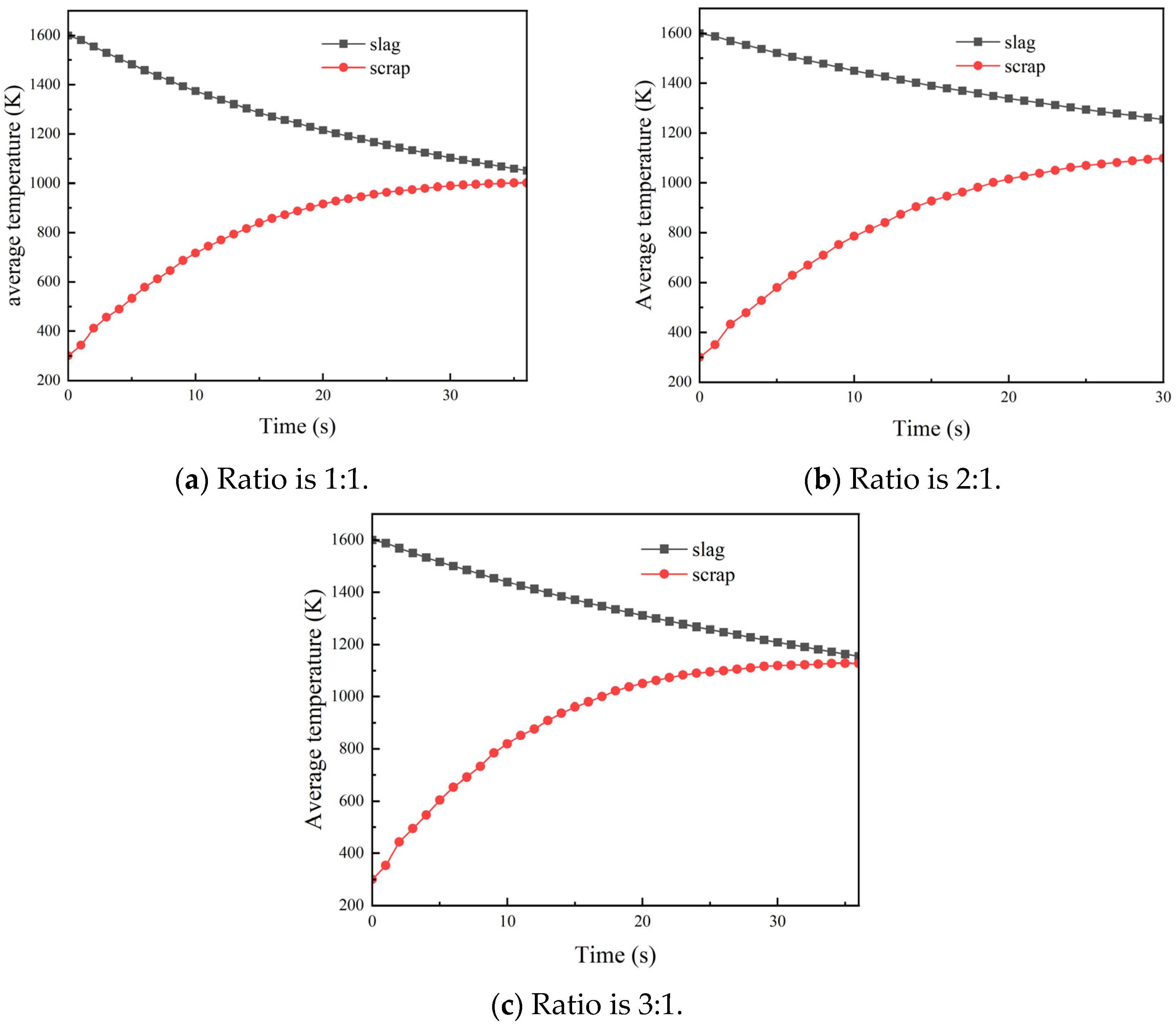
Figure 6.
Probability density function of temperature at different slag–steel ratios.
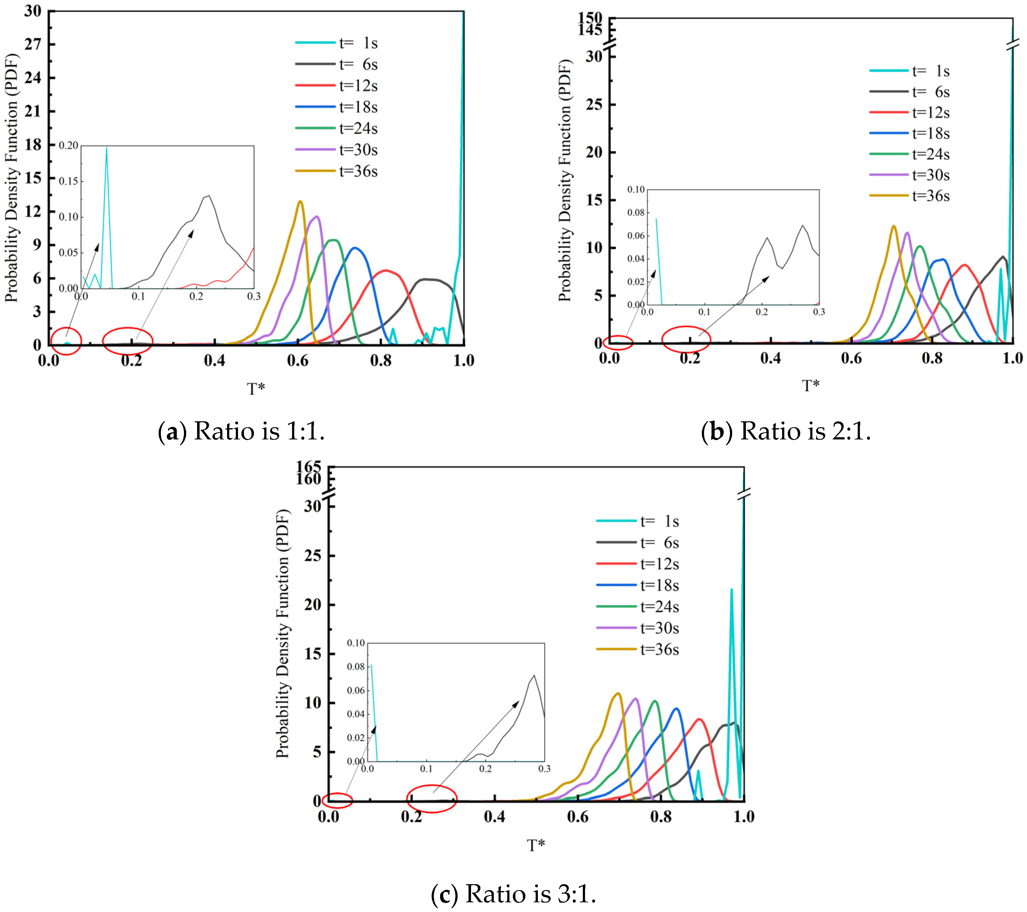
Figure 7.
3D stacking of particles inside the drum with time as well as temperature for a slag-to-steel ratio of 2:1.
Figure 7.
3D stacking of particles inside the drum with time as well as temperature for a slag-to-steel ratio of 2:1.

Figure 8.
Heat transfer state of particles in the drum when the shape of scrap steel is different.

Figure 9.
Average temperature of high-temperature slag and scrap in the drum as a function of time for different scrap shapes.
Figure 9.
Average temperature of high-temperature slag and scrap in the drum as a function of time for different scrap shapes.

Figure 10.
Temperature probability density function when scrap shape is different.
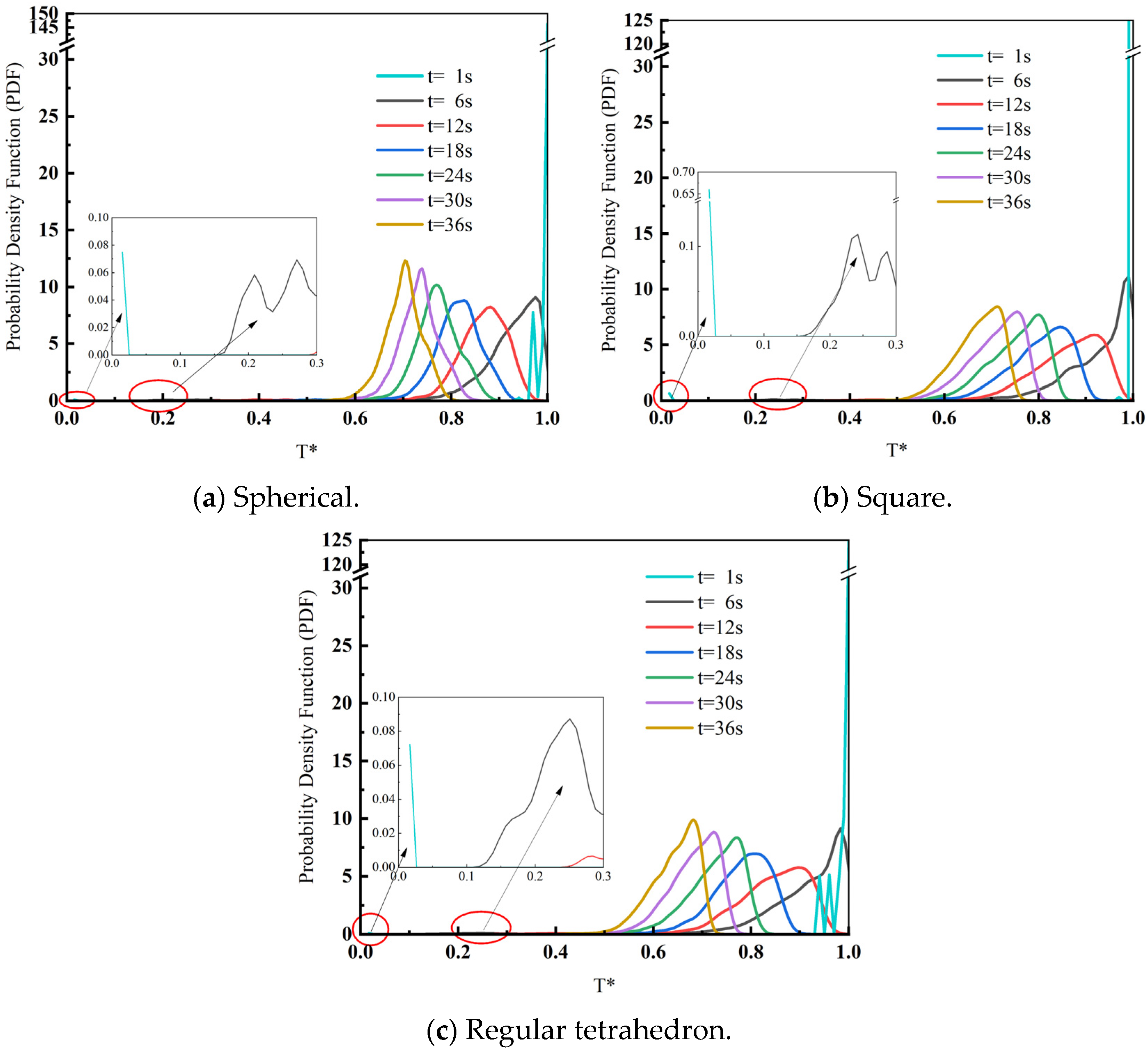
Figure 11.
Heat transfer state of particles in the drum when the drum speed is different.
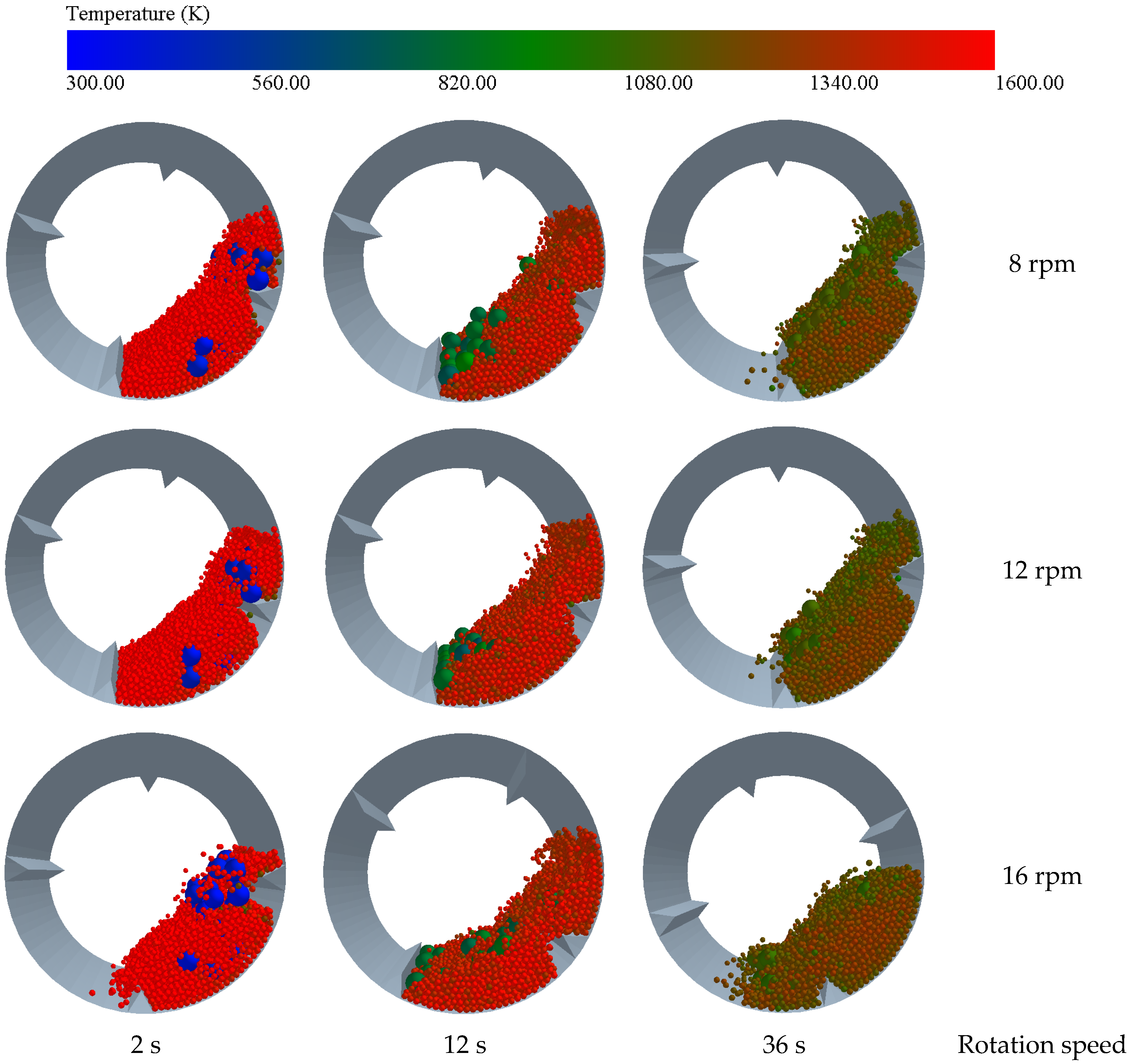
Figure 12.
Average temperature of high-temperature slag and scrap in the drum as a function of time for different drum speeds.
Figure 12.
Average temperature of high-temperature slag and scrap in the drum as a function of time for different drum speeds.

Figure 13.
Temperature probability density function at different drum speeds.

Table 1.
Physical parameter.
| Physical Properties | Unit | Slag | Scrap |
|---|---|---|---|
| Densities, ρ | Kg/m3 | 2800 | 7800 |
| Poisson’s ratio, ν | 0.25 | 0.3 | |
| Shear modulus, E | Pa | 1 × 10⁸ | 8 × 10¹⁰ |
| Specific heat capacity, Cp | J/(Kg·K) | 1105 | 460 |
Table 2.
Influencing factors and values.
| Influencing Factors | Values |
|---|---|
| The ratio of slag to steel | 3:1, 2:1, 1:1 |
| The shape of scrap steel | Spherical, cube, tetrahedral |
| Drum speed | 8 rpm, 12 rpm, 16 rpm |
Table 3.
Physical parameter.
| Physical Properties | Unit | Quartz Sand | Fiberglass |
|---|---|---|---|
| Densities, ρ | Kg/m3 | 2650 | 1680 |
| Poisson’s ratio, ν | 0.25 | 0.2 | |
| Shear modulus, E | Pa | 5 × 10⁸ | 5 × 10¹⁰ |
| Specific heat capacity, Cp | J/(Kg·K) | 1080 | 800 |
Table 4.
Comparison of average temperature and deviation of scrap steel under different grid sizes.
| Mesh Size | 0.1 R | 1 R | 2.5 R | 5 R | 10 R |
|---|---|---|---|---|---|
| Average temperature of scrap/K | 990 | 995 | 998 | 950 | 1056 |
| deviation | — | 0.51 | 0.82 | 4.04 | 6.67 |
Disclaimer/Publisher’s Note: The statements, opinions and data contained in all publications are solely those of the individual author(s) and contributor(s) and not of MDPI and/or the editor(s). MDPI and/or the editor(s) disclaim responsibility for any injury to people or property resulting from any ideas, methods, instructions or products referred to in the content. |
© 2024 by the authors. Licensee MDPI, Basel, Switzerland. This article is an open access article distributed under the terms and conditions of the Creative Commons Attribution (CC BY) license (https://creativecommons.org/licenses/by/4.0/).
Share and Cite
MDPI and ACS Style
Fan, G.; Su, F.; Zhao, Q.; Li, C.; Li, B. Study on Heat Transfer Process between High-Temperature Slag Particles and Scrap in Drum Based on DEM Method. Processes 2024, 12, 815. https://doi.org/10.3390/pr12040815
AMA Style
Fan G, Su F, Zhao Q, Li C, Li B. Study on Heat Transfer Process between High-Temperature Slag Particles and Scrap in Drum Based on DEM Method. Processes. 2024; 12(4):815. https://doi.org/10.3390/pr12040815
Chicago/Turabian StyleFan, Guangyan, Fuyong Su, Qianlong Zhao, Cunwang Li, and Bin Li. 2024. "Study on Heat Transfer Process between High-Temperature Slag Particles and Scrap in Drum Based on DEM Method" Processes 12, no. 4: 815. https://doi.org/10.3390/pr12040815
Note that from the first issue of 2016, this journal uses article numbers instead of page numbers. See further details here.