
Impact of Wellbore Cross-Sectional Elongation on the Hydraulic Fracturing Breakdown Pressure and Fracture Initiation Direction

Department of Civil Engineering, Faculty of Engineering, University of Zanjan, Zanjan 45371-38791, Iran
*
Author to whom correspondence should be addressed.
Processes 2024, 12(5), 848; https://doi.org/10.3390/pr12050848
Submission received: 18 March 2024
/
Revised: 16 April 2024
/
Accepted: 21 April 2024
/
Published: 23 April 2024
Abstract
:Investigation of breakdown pressure in wellbores in complex conditions is of great importance, both in fracture design and in wellbore log interpretation for in situ stress estimation. In this research, using a two-dimensional numerical model, the breakdown pressure is determined in ellipsoidal and breakout wellbores. To find the breakdown pressure, the mixed criterion is used, in which the toughness and the tensile strength criteria must be satisfied concurrently. In breakout boreholes, the breakdown pressure is lower than the circular wellbores; indeed, the ratio of the breakdown pressure of the breakout wellbore to the breakdown pressure in the circular wellbore is between 1 and 0.04, depending on the deviatoric stress and the width and depth of the breakout zone. In breakout wellbores, the fracture initiation position depends on the deviatoric stress. In small deviatoric stresses, the fracture initiation position is aligned with the minimum in situ stress, unlike circular boreholes; and in large deviatoric stresses, the fracture initiates in the direction of the major principal stress. In large wellbores, the breakdown pressure is controlled by the tensile strength of the rock; and in small wellbores, the breakdown pressure is under the control of the energy spent to create new crack surfaces.
1. Introduction
There are several reasons why a wellbore cross-section may become non-circular. One of the possible causes is the mechanical action of the drill string on the well after drilling; also, the elastic deformations after drilling give the cross-section of the borehole a degree of ovality. The washout of soft formations near the wellbore also causes the cross-section of the borehole to become non-circular. The concentration of compressive stress in the borehole wall causes a type of progressive failure, which is called borehole breakout. Wellbore breakout also causes elongation of the wellbore cross-section. In the borehole breakout, the expansion of the wellbore cross-section is aligned with the minor in situ stress. The stress concentration along the wall of such a non-circular wellbore depends not only on the in situ stresses, but also on the wellbore cross-section shape. If hydraulic fracturing is performed for such a wellbore, the fracture initiation position and breakdown pressure may be different from that obtained for a circular borehole.
To calculate the breakdown pressure of hydraulic fracturing in circular wellbores, two classic theoretical criteria of Hubbert and Willis (HW) [1] and Haimson and Fairhurst (HF) [2] are usually used. The HW criterion is simply gained from the theory of elasticity. This criterion assumes that for wellbore under horizontal in situ stresses and , tensile fracture occurs when the hoop stress along is reduced to the rock tensile strength. This criterion provides the breakdown (fracture initiation) pressure according to Equation (1).
In this relationship, is the breakdown pressure, and are the maximum and minimum horizontal in situ stress perpendicular to wellbore axis, respectively, and is the rock tensile strength. The HF criterion given in Equation (2) is simplified from a more general expression in which poroelastic effects are also taken into account. This criterion provides breakdown pressure as Equation (2)
These two criteria were presented for a simple case of hydraulic fracturing for circular wellbores and are not suitable for complex conditions of hydraulic fracturing.
Investigating the fracture process in complex wellbore conditions is important not only for fracture design, but also for the interpretation of well logs used to estimate in situ stress. It has been observed that most wellbores in the North Sea have some degree of non-circularity or oval shape, and this was the motivation for the theoretical studies of Aadnoy and Angell-Olsen [3]. Using circumferential (hoop) stress equations around the wellbore, they showed that the fracture initiation pressure for an oval borehole is different from a circular borehole. They also found that the fracture initiation position is the same in both wellbores except for the case where the stress ratio is larger than the ellipticity [3]. Akgun et al., using a finite-element numerical model and ANSYS v5.2 software, showed that in elongated wellbores due to breakout, the hydraulic fracture initiation pressure is slightly reduced, but the fracture initiation position does not change [4]. Using a numerical model, Zhang et al. showed that the fracture paths and pressure required for fracture propagation both depend on the wellbore shape when the fracture initiates at a location that is not aligned with the maximum principal in situ stress, and the wellbore geometry does not significantly affect the initiation pressure when the fracture initiates align with the maximum principal stress direction [5]. Using a developed inverse technique, Han et al. worked on the evaluation of in situ stresses in elliptical wellbores with arbitrary trajectory [6]. Their results showed that the difference in the axes of the elliptical wellbore even by 2% causes a 5% difference in the estimation of the minimum horizontal stress and also causes a 10% difference in the estimation of the maximum horizontal stress. Liu et al., by performing hydraulic fracturing experiments on oval wellbores representing breakout wells, found that the shape of the wellbore and the difference between in situ stresses has a meaningful impact on the breakdown pressure of hydraulic fracture in sandstones. So when there is a deviatoric stress, the breakdown pressure declines with the increase in the minor axis of the oval wellbores; but in the absence of deviatoric stress (isotropic field stress), the situation is completely opposite. They also found that if the wellbore is circular, the breakdown pressure is negatively correlated with the horizontal stress difference [7]. The authors investigated the breakdown pressure and fracture initiation site in oval wellbores using only the tensile strength criterion and an analytical model [8]. We found that when the in situ stress field is isotropic, the fracture initiates in the direction of the major radius of the wellbore, and as the eccentricity increases, the breakdown pressure decreases.
But it is not only the geometry of the wellbore that affects the breakdown pressure, but the injection rate, the size of the wellbore radius and the compliance of the injection system also affect the fracture initiation pressure or breakdown pressure. The effects of the injection rate on breakdown pressure can be investigated by considering a defect in the wellbore wall from which the fracture propagates [9,10,11,12,13,14]. Laboratory tests clearly show that the breakdown (initiation) pressure increases with an increase in the pressurization rate, or with a declines in the wellbore radius [9,15,16,17,18,19]. The effects of the injection rate are also reported in the field. Lakirouhani et al. investigated the effect of the compressibility of the injection system, initial crack length and viscosity on the breakdown pressure using a two-dimensional mathematical/numerical model with plane strain assumption [19]. Ito and Hayashi investigated the effect of the injection rate and cavity radius on fracture initiation pressure using a theoretical model and laboratory experiments. They postulated that tensile fracture initiates just after the tangential stress at a situation far from the wellbore wall reduces to the rock tensile strength. Ito and Hayashi introduced the distance between the wellbore wall and that point and as a material constant. Their results showed that the breakdown pressure declines with increasing wellbore radius and increases with increasing pressurization rate [9].
Carter and Carter et al., with uniaxial compression tests performed on rock blocky samples with a cavity, showed that for a very small hole radius, the compressive stress causing tensile failure is high; and with increasing hole size, it decreases and approaches a horizontal asymptote [20,21]. Leguillon showed that both the fracture toughness principle and the tensile stress model are essential conditions for the fracture initiation, and neither of them alone is sufficient. It was then found that size effects result from the interplay of crack increment and further characteristic length [22,23]. The interpretation of the duality between tensile strength and toughness on breakdown pressure can be investigated from the point of view of non-linear fracture mechanics [24]. However, recently, the conception of combining the fracture toughness principle and the tensile stress model to find the breakdown pressure and fracture initiation length has been used by some researchers [24,25,26]. Using displacement discontinuity numerical method and dual strength and toughness criterion, Zhou et al. obtained the breakdown pressure in the breakout wellbores and found that the effect of the borehole geometry on the breakdown pressure is very small and imperceptible [27]. We recently obtained the hydraulic fracture initiation pressure using a numerical model with coupled criteria and fracture mechanics criteria and compared the results of the initiation pressure with the classical hydraulic fracture criteria based on tensile strength (that is, Equations (1) and (2)). We found that the initiation pressure gained from the dual criterion has a strong dependence on the wellbore size, so that for a small-cavity radius, the toughness criterion governs the fracture mechanism, and for a large-cavity radius, the fracture mechanism is in accordance with the tensile strength criterion [28].
Obtaining the breakdown pressure and investigating the factors affecting it are of great importance in geomechanics because the breakdown pressure is used in the prediction of field stress and also in fracture design. Despite the many studies that have been performed on circular wellbores, fewer studies have been performed on non-circular and breakout wellbores; furthermore, few previous studies have clearly defined the effect of wellbore breakout and wellbore cross-sectional expansion on breakdown pressure. The purpose of this study is to evaluate the effect of wellbore geometry and wellbore size on the breakdown pressure and fracture initiation location. Analyses are performed on ellipsoidal and breakout wellbores; and for them, the breakdown pressure is found using the validated mixed criterion. In the mixed criterion, the tensile failure initiates in the wellbore wall when both the fracture toughness model and the tensile strength model are met concurrently. Modeling is two dimensional and assumes plane strain conditions. Using a code written on the basis of the FEM and MATLAB R2018a software, the problem is solved. The obtained results are useful and important both in the field and in hydraulic fracturing laboratory tests.
2. Problem Definition, Mixed Criterion
2.1. Elliptical Wellbores
Figure 1 illustrates the problem geometry for an elliptical wellbore. In this figure, a cross-section of the wellbore under field stresses and is shown. If the wellbore is vertical and one of the principal stresses is aligned with the center line of the wellbore, then and are the maximum and minimum horizontal in situ stresses, respectively . is the minor radius of the ellipse and is the major radius of the ellipse. is the wellbore pressure, which has a uniform distribution on the wellbore wall. The rock is supposed to be impermeable and has a linear elastic behavior with the characteristics of Poisson’s ratio , the modulus of elasticity , the tensile strength , and fracture toughness .
2.2. Breakout Wellbores
Figure 2 illustrates the problem geometry for a breakout wellbore. Breakout is shear failure caused by compressive stress that is formed symmetrically on both sides of the wellbore and along the minimum in situ stress [29,30,31]. Breakout failure expands episodically with the separation of crushed rock layers until it reaches stability. The breakout failure zone is V shaped or dog eared and has two characteristics, width and depth [32,33,34,35,36,37]. According to field reports, breakouts have been observed in different types of rocks such as limestone, siltstone, granite, dolomite and sandstone [38,39,40].
2.3. The Numerical Model
To solve the problem presented in the previous sub-sections, the FEM is used. Thus, the geometries shown in Figure 1 and Figure 2 are meshed using eight node elements. The boundary conditions that are a combination of traction and displacement are applied at the domain of the model. The left and bottom boundaries are on the roller, and field stresses are assigned to the right and top boundaries. Figure 3 and Figure 4 show the geometry of the model for the ellipsoidal and the breakout wellbore, respectively. Verification of the finite-element model is given in Appendix A.
2.4. The Mixed Criterion, Procedure for Finding Hydraulic Fracture Breakdown Pressure and Initiation Length
As mentioned in the introduction, the mixed criterion is used to find the wellbore breakdown pressure in this paper. In the mixed criterion, the breakdown occurs when both toughness and the rock tensile strength criteria are satisfied at the same time:
where is the circumferential (hoop) stress at a distance from the wellbore wall, is the stress intensity at the fracture tip with length , is the wellbore pressure that acts uniformly on the wellbore surface, is the rock tensile strength, and is the fracture toughness. If both criteria are met simultaneously, the obtained length is the fracture initiation length and the minimum wellbore pressure obtained is the breakdown pressure . In fact, the compatibility of the two criteria provides a new form of a general criterion for crack initiation. This criterion provides both breakdown pressure and fracture initiation length. The initiation length is the length that is assumed at the onset of failure, the crack jumps to this length. To evaluate the first condition of relation 3 (toughness criterion), two transverse symmetrical cracks are considered in the wellbore wall, and since this condition must be satisfied between the cracked and un-cracked state, the fluid pressure on the crack surfaces is not considered, in other words, it is assumed that, at the moment of initiation, the fluid has not yet penetrated within the crack. Here, to calculate the stress intensity factor, the J-integral technique has been used, which is accurate, and the model has been validated in this regard in Appendix A. The second condition of relation 3 (strength criterion) is evaluated in the absence of a crack, that is, the tensile stress must exceed the rock tensile strength in all the lengths of the crack that has not yet been created.
In wellbores with circular cross-sections, the initiation of hydraulic fracture is along the major in situ stress, but in ellipsoidal wellbores or breakout wellbores, due to the elongation of the cross-section, the initiation of fracture can also occur along the other direction. For this reason, in this article, the conditions of relation 3 are controlled both along and along , and the breakdown pressure is determined for these two directions, consequently, the minimum of them is the breakdown pressure and the corresponding direction is the fracture initiation direction.
But to solve the two criteria of relation 3 at the same time and find the breakdown pressure and the fracture initiation length, the breakdown pressure curves gained from each criterion are drawn in one plot. The intersection point of two curves shows the breakdown pressure and fracture initiation length. Figure 5 shows an illustration of obtaining fracture initiation length and breakdown pressure for a breakout wellbore with the specifications presented in Table 1. The width and depth of the breakout are presented in Figure 5a. In Figure 5b, the red curve displays the wellbore pressure against the flaw length gained from the tensile strength theory (second term in Equation (3)) and the blue curve presents the wellbore pressure versus the crack length gained from the fracture toughness theory (the first law of Equation (3)). The intersection point of two curves indicates the breakdown pressure and the fracture initiation length based on the mixed criterion. Calculations are performed both along the maximum in situ stress and along the minimum in situ stress ; and for each direction, the breakdown pressure is obtained. The minimum wellbore pressure obtained for two directions is the breakdown pressure, accordingly, the tensile fracture initiates in the direction for which the breakdown pressure is minimum. So for this example
Using the solution procedure described above, all models of ellipsoidal and breakout wellbores are analyzed and the breakdown pressure is calculated for them. The results are given below. Verification of the numerical model for the stress intensity factor and circumferential stress is very important; the verification is performed in this regard and is given in Appendix A.
3. Results for Elliptical Wells
3.1. The Effect of the Wellbore Shape Parameter on Fracture Initiation Position and Breakdown Pressure
The analysis presented in this research work has been performed for the characteristics of the materials given in Table 1. Also, is considered constant in all analyses. The shape parameter is defined as follows and indicates the eccentricity of the ellipsoidal wellbore cross-section:
where is the minor radius of the ellipse and is the major radius of the ellipse, and for circular wellbore , parameter indicating the dimensionless deviatoric stress is also defined as follows:
For the sake of brevity, the analysis performed in this section has been for ; however, the model has no limitations for calculating the breakdown pressure for large .
Figure 6 shows the wellbore breakdown pressure obtained from the mixed criterion versus for different values of . Here, and has been changed to create a different cross-section. Several results can be obtained from this plot, which are described below. In the case where , with the increase in , the breakdown pressure declines; instead, if the in situ stress field is anisotropic , with the increase in , the breakdown pressure increases until it reaches a maximum value, and then with the increase in , the breakdown pressure declines. For , the maximum breakdown pressure occurs for the critical shape parameter .
For the case where (isotropic in situ stresses), the fracture initiates along the major diameter of the borehole or minimum in situ stress . If the in situ stress field is anisotropic , for , the fracture initiation is aligned with the major in situ stress or the minor diameter of the wellbore ; and for , the fracture initiation is aligned with the minor in situ stress or the major diameter of the ellipse ; and if , the chances of fracture initiation being along or are the same.
When (isotropic stress field), the expansion of the wellbore cross-section causes more wellbore pressure to be applied to the wall of the wellbore (the pressure increases in the direction of the minor radius of the ellipse), so the fracture initiates in the direction of the major radius of the ellipse, and by increasing the shape factor, the surface under wellbore pressure increases and the breakdown pressure declines; in such a situation, fracture initiation direction and the breakdown pressure are under the control of wellbore elongation.
However, if , when , due to the small elongation of the wellbore, it is no longer decisive in determining the position of tensile fracture, and the initiation of tensile rupture is under the control of deviatoric stress. Meanwhile, with the increase in , the dominance of the wellbore elongation gradually increases, because when , with the rise of the shape factor, the breakdown pressure increases; in this situation, the initiation of fracture is aligned with the , like circular wellbores under an anisotropic stress field. When , wellbore elongation and deviator stress have a 50/50 effect on the fracture initiation position and breakdown pressure. With a further increase in , and when , the initiation of fracture is dominated by the elongation of the wellbore; in this situation, with the increase in the shape factor, the surface under the wellbore pressure gradually increases, and therefore, the breakdown pressure has a decreasing trend.
Figure 6 shows that with the increase in the dimensionless deviatoric stress, the critical shape parameter and the breakdown pressure at the increase. The obtained from the numerical calculation on the basis of the mixed criterion is similar to the critical shape parameter obtained from the analytical model. In our previous article, based on a simple analytical model, we obtained the critical shape parameter as follows [8]:
This relationship shows that with increasing rock tensile strength, decreases; as a result, considering the fact that for the rock materials , by comparing Equation (4) with Equation (6) and a little manipulation, we find that if:
then the cross-section of the wellbore has the most strength against tensile failure.
3.2. The Effect of Wellbore Size on Breakdown Pressure Behavior
In this sub-section, the impact of the size of the ellipsoidal wellbore on the breakdown pressure and fracture initiation length is investigated. For this purpose, we consider four series of ellipsoidal wellbore cross-sections according to Figure 7. In each series of wellbores, the small and large diameters of the ellipsoidal cross-section of the wellbore are enlarged by a constant factor, so that the shape parameter remains constant. Series A wellbores have shape parameter , series B wellbores have shape parameter , series C wellbores have shape parameter , and series D wellbores have shape parameter (Figure 7). In the following, the results of the analysis performed on these four series of models, in the conditions where the field stress are anisotropic and isotropic, are presented.
3.2.1. The Isotropic Stress Field
Figure 8 shows the breakdown pressure obtained from the mixed criterion versus the semi-minor axis of the wellbore cross-section for different values of the shape factor in the case that the stress field is isotropic . This figure shows that the breakdown pressure first has a sharp decline, and then gradually decreases until it tends to a horizontal asymptote. As previously observed, if the in situ stresses are isotropic, the tensile fracture initiates in the direction of major axis of the ellipse . Now, we want to examine the results in a dimensionless space. First, we make the breakdown pressure dimensionless by the breakdown pressure gained from the tensile strength model. In the situation that the field stress is isotropic, the breakdown pressure determined by the rock tensile stress model and using the relationship of hoop stress distribution around the elliptical wellbores is as follows [8]:
where , and the initiation of the fracture is aligned with the major radius of the wellbore . The breakdown pressure obtained from only a tensile strength criterion based on Equation (8) is dependent on the shape factor, rock tensile strength, and in situ stress and is independent of the wellbore size. Next, semi-minor axis of the wellbore made dimensionless by the Irwin length scale as follows:
is the ratio of the minor radius of the wellbore to Irwin length scale .
In Figure 9, we plot the ratio of the dimensionless breakdown pressure gained from the mixed criterion versus the dimensionless semi-minor axis of the wellbore . It can be seen that all four curves of Figure 8, which were for different values of the shape parameter, coincide with each other in the dimensionless space. But the interesting aspect of Figure 9 is that it shows the effect of the size of the wellbore on the mechanism controlling the tensile failure of the borehole. Simply put, it can be seen in this figure that for , , and this means that in wellbores with a large cross-sectional area, the breakdown pressure is dominated by the tensile strength of the rock; however, for small values of (small wellbore radius), the breakdown pressure is controlled by the energy spent to create new crack surfaces. When the wellbore size is small enough, the breakdown pressure gained from the mixed criterion shows a strong singularity. Figure 10 shows the fracture initiation length versus . The double-log curves in this plot illustrate that the fracture initiation length has relatively little sensitivity to the shape factor; in addition, the tensile strength criterion provides an upper bound for the fracture initiation length, while the toughness criterion results in a lower bound for the fracture initiation length. At the initiationit is supposed that the flaw to jump the fracture initiation length.
3.2.2. The Anisotropic Stress Field
The analysis in this section has been performed for dimensionless deviatoric stress . According to Figure 6 and for this dimensionless deviatoric stress, . Numerical analyses are performed for four series of wellbores shown in Figure 7, and fracture initiation position and the breakdown pressure are determined for them based on the mixed criteria. The results are shown in Figure 11 and Figure 12. A- and B-series wellbores have a shape factor lower than the critical shape factor, so the initiation of fracture in them is along the minor axis of the wellbore or maximum in situ stress . Figure 11 illustrates the breakdown pressure versus wellbore size for A and B series wellbores with shape factors of 0 and 0.1, respectively. The shape factor of C and D series wellbores is larger than the critical shape factor, so the initiation of fracture for these wellbores is aligned with the major radius of the ellipse or the minimum in situ stress . Figure 12 illustrates the breakdown pressure versus wellbore size for series C and D wellbores with shape factors of 0.2 and 0.3, respectively. Here, we also want to display the results in dimensionless space.
Here again, we want to represent the results in dimensionless space, and again the breakdown pressure is made dimensionless by the breakdown pressure resulting from the tensile strength theory, because the breakdown pressure resulting from the tensile stress theory is independent of the wellbore size and just depends on the shape factor, rock tensile strength and in situ stress. Briefly, according to the rock tensile strength theory, in the conditions where and , the breakdown pressure is obtained from relations (10) and (11), respectively [8]:
Now, using these two relationships, we can examine Figure 11 and Figure 12 in dimensionless plots. Figure 13 shows the dimensionless breakdown pressure (made dimensionless by relation (10)) for series A and B wellbores with a shape factor of 0 and 0.1 and Figure 14 shows the dimensionless breakdown pressure (made dimensionless by relation (11)) for series C and D wellbores with a shape factor of 0.2 and 0.3. Similarly to Figure 9, Figure 13 and Figure 14 also show the dependence of breakdown pressure behavior on wellbore size. Figure 15 illustrates the fracture initiation length versus .
4. Results for Breakout Wellbores
In this section, using the mixed criterion, we determine the breakdown pressure and fracture initiation position for the breakout wellbores. We had previously obtained the final breakout area for different deviatoric stresses and different rock characteristics using the finite-element numerical method and based on an episodic failure algorithm [41], which is summarized in Figure 18. In the breakout wellbores shown in this figure, the breakout width is between and , and for each breakout width, different breakout depths from 1.25 to 1.80 have been considered, where . For all these models, the breakdown pressure and fracture initiation position are obtained and compared with the values obtained for the circular wellbore. Below are the results.
4.1. The Effect of Breakout Depth on Breakdown Pressure
The results of the analysis performed on the breakout wellbores shown in Figure 18, are given in Figure 19 and Figure 20. In these figures, the breakdown pressures are scaled with the breakdown pressure for a circular wellbore with the same deviatoric stress. In these figures, it can be seen that for all the models presented in Figure 18, and different values of dimensionless deviatoric stresses, ; this indicates that the breakdown pressure in the breakout wellbore is lower than the breakdown pressure in the circular wellbore with the same deviatoric in situ stress.
In breakout wellbores, for , fracture initiation occurs along the minimum in situ stress or at the breakout tip ; this state is different from the state that occurs in circular wellbores, in circular wellbores, the initiation of hydraulic fracture is always along the maximum in situ stress. For , fracture initiation is aligned with the maximum in situ stress , like the circular wellbores. In other words, when , the effect of wellbore elongation is greater than the effect of stress anisotropy in determining the fracture initiation position; in this case, the fluid pressure on the breakout surfaces reduces the tangential stress at the breakout tip, and this causes the fracture initiation to occur at this location. But when , the hoop stress reduction along the maximum in situ stress due to the anisotropy of the field stress is more than the hoop stress reduction at the breakout tip due to the fluid pressure on the breakout surface, and in this condition, the fracture initiates aligned with the maximum in situ stress.
4.2. The Effect of Breakout Width on Breakdown Pressure
4.3. The Effect of Deviatoric In Situ Stress on Breakdown Pressure
Figure 23 and Figure 24 show the scaled breakdown pressure versus the dimensionless deviatoric stress for breakout widths of and , respectively. Breakdown pressure scaling is not performed uniformly for all models, because circular wellbores under different deviatoric stresses have different breakdown pressures. In these two figures, it can be seen that with the increase in the dimensionless deviatoric stress up to 0.9, the breakdown pressure increases, and in this range, the fracture initiation is aligned with the minimum horizontal in situ stress ; then after that, with the increase in the deviatoric stress from 0.9 to 2.5, the breakdown pressure declines with the increase in the deviatoric stress, and in this range, the fracture initiates aligned with the maximum horizontal in situ stress .
In the dimensionless deviatoric stress , the breakdown pressure obtained from the mixed criterion for the breakout wellbore is almost identical to the breakdown pressure in the circular wellbore with the same deviatoric stress, and the breakdown pressure obtained for different depth and width of breakout have insignificant differences with each other. At this point, the fracture initiation position changes from to . In other words, at this point, the fracture initiation position that was controlled by wellbore elongation due to breakout, is released, and becomes dominated by deviatoric stress. But why for , the breakdown pressure increases and for , it decreases? For , the initiation of the fracture is along , i.e., the region of the breakout tip. As the deviatoric stress increases, the positive tangential stress increases in this area, which means that more wellbore pressure is required to initiate tensile fracture in this area. But for , the initiation of fracture is along , with the increase in deviatoric stress, the positive tangential stress decreases in this region, and this means that less wellbore pressure is needed to initiate fracture in this region.
4.4. The Effect of Wellbore Size on Breakdown Pressure
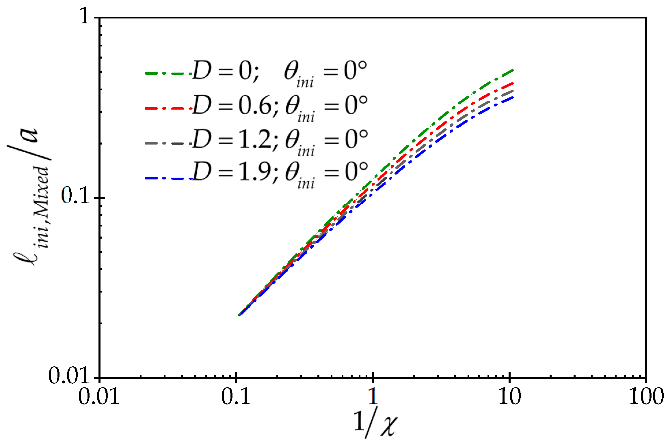
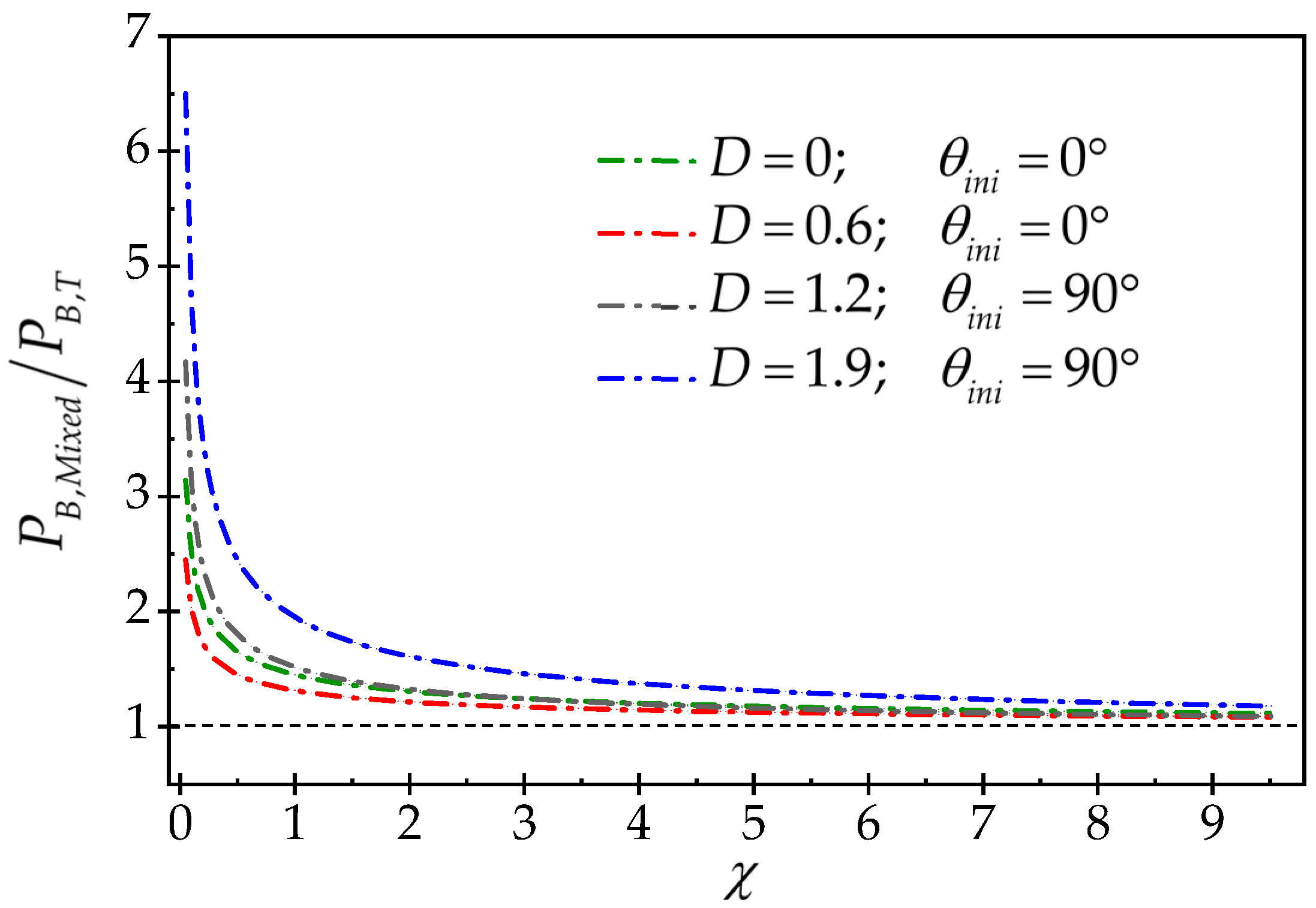
In this section, to study the effect of wellbore diameter (size effect), a series of breakout wellbores that have the same breakout depth and width, according to Figure 25, are considered. For this series of wellbores, the breakout depth and width are equal to and , respectively. The series of wellbores shown in Figure 25, although they have the same breakout depth and width, have different diameters. Here, the breakdown pressure gained from the mixed criterion makes dimensionless by the breakdown pressure gained from the tensile strength theory. However, due to the geometrical complexity of the cross-section of the breakout wellbores, a closed-form relationship for breakdown pressure based on the tensile strength criterion cannot be obtained. Therefore, using the finite-element numerical method by applying the condition on the wellbore wall, the breakdown pressure is obtained for each model. The breakdown pressure gained from the tensile stress theory and using the numerical method, for a certain field stress, is constant and independent of the size. The result is given in Figure 26. Figure 26 shows the dimensionless breakdown pressure versus the dimensionless wellbore radius. This figure is for four different deviatoric stresses and it can be seen that for and , the fracture initiation is aligned with the minimum in situ stress ; and for and , the fracture initiation is aligned with the maximum in situ stress . Once again, we can see the effect of wellbore size in this figure; this means that for large wellbore radii, the tensile fracture mechanism is under the control of the rock tensile strength criterion, and for small wellbore radii, it is fracture toughness criterion that dominates the failure mechanism. Figure 27 shows the dimensionless fracture initiation length versus .
5. Discussion
The main goal of this research was to study the effect of wellbore cross-sectional area elongation on breakdown pressure and fracture initiation position; however, the effect of wellbore size on breakdown pressure was also investigated using the mixed criteria. The numerical studies carried out in this article showed that the elongation of the wellbore cross-section increases the surface of the wall under the pressure of the wellbore, and this affects the hydraulic fracture breakdown behavior and fracture initiation position. In an elliptical wellbore, depending on the value of deviatoric stress and the value of eccentricity of the wellbore, the breakdown pressure can be higher or lower than the breakdown pressure of the wellbore with zero eccentricity (circular wellbore). But in the breakout wellbores, the breakdown pressure is lower than the breakdown pressure in the circular wellbore under the same in situ stress; however, in breakout wellbores, the position of fracture initiation is under the control of deviatoric stress and wellbore geometry. The results obtained in this article are very important in the field, where it is supposed to estimate the in situ stress based on the breakdown pressure or in the design of the hydraulic fracture path. But the preference of using the mixed criterion over the tensile strength criterion in determining the breakdown pressure is that the mixed criterion showed that the breakdown pressure is also affected by the size of the wellbore. So, in summary, eccentricity in elliptical wellbores and breakout dimensions in breakout wellbores, in situ deviatoric stress value and wellbore size affect the behavior of hydraulic fracture breakdown pressure. In the next section, the results are presented separately.
6. Conclusions
In this research, using a two-dimensional numerical model based on the finite-element method, an attempt was made to determine the hydraulic fracture breakdown pressure and fracture initiation site in ellipsoidal and breakout wellbores using the mixed criteria.
The analyses performed on elliptical wellbores led to the following results:
- For each deviatoric stress, there is a critical shape factor. If the wellbore shape factor is less than the critical shape factor, the breakdown pressure increases with the increase in the shape factor; for this case, the fracture initiation site is aligned with the major principal stress (like circular wellbores) or minor diameter of the ellipse. If the wellbore shape factor is greater than the critical shape factor, the breakdown pressure will decrease as the shape factor increases, and in this situation, the fracture initiation site is aligned with the minor principal stress or major diameter of the wellbore, unlike the circular wellbores.
- According to Equation (6), the critical eccentricity is in control of the deviatoric stress and the rock tensile strength, it increases by increasing the deviatoric stress or decreasing the tensile strength of the rock.
- The mixed model strongly represents the impact of wellbore size on the breakdown pressure behavior. The analyses performed on elliptical wellbores with the same shape factor but different size show that in large wellbores, the tensile fracture mechanism and breakdown pressure are dominated by the rock tensile strength criterion, but in small wellbores, the fracture mechanism is dominated by fracture toughness.
The main results obtained in the case of breakout boreholes:
- The main finding of the section of breakout wellbores is that it was observed that for a given in situ stress, the breakdown pressure in the breakout wellbore is always lower than that of the circular wellbore. As shown in the following results, wellbore elongation has a significant effect on both breakdown pressure and failure initiation position.
- Where , fracture initiation is aligned with the minor in situ stress or breakout tip, and the ratio of breakdown pressure in the breakout wellbore to the breakdown pressure of the circular wellbore is between 0.47 and 1, depending on the deviatoric stress and the width and depth of the breakout zone. In this case, with the rise of the dimensionless deviatoric stress, the breakdown pressure increases.
- Where , the initiation of fracture is aligned with the maximum in situ stress, while, the ratio of the breakdown pressure of the breakout wellbore to the breakdown pressure in the circular wellbore is between 1 and 0.04, depending on the deviatoric stress and the width and depth of the breakout zone. In this case, with the rise of the dimensionless deviatoric stress, the breakdown pressure declines.
- As the breakout depth increases, the breakdown pressure declines.
- The effect of wellbore size in breakout wellbores with the same breakout depth and width but different diameters was investigated and it was seen that similar to elliptical wellbores, the breakdown pressure in large-diameter wellbores is dominated by the tensile strength theory, while the breakdown pressure in small wellbores is dominated by the fracture toughness criterion.
Author Contributions
Conceptualization, A.L.; methodology, A.L.; software, S.J.; validation, S.J.; formal analysis, S.J.; investigation, A.L. and S.J.; writing—review and editing, A.L.; original draft preparation, S.J. supervision, A.L. All authors have read and agreed to the published version of the manuscript.
Funding
This research received no external funding.
Data Availability Statement
The data that support the findings of this study are available from the corresponding author, upon reasonable request.
Conflicts of Interest
The authors declare no conflict of interest.
Appendix A. Numerical Model Verification
To investigate the accuracy of the obtained from the numerical model, we consider a state where , and . We compare the obtained from the numerical model with the analytical solution provided by Rummel [42]. According to the principle of superposition, the stress intensity factor for the complex loading illustrated in Figure A1 is obtained as follows:
where is the stress intensity factor, and are the maximum and minimum in situ stresses, respectively, and is the wellbore pressure. The components of relation (A1) are obtained from the following relations:
where . Figure A2 confirms the validity of the numerical model by comparing the obtained from the numerical model with the obtained from the analytical relationship given above.
Figure A1.
Configuration of circular wellbore with two symmetrical cracks along maximum in situ stress.
Figure A1.
Configuration of circular wellbore with two symmetrical cracks along maximum in situ stress.
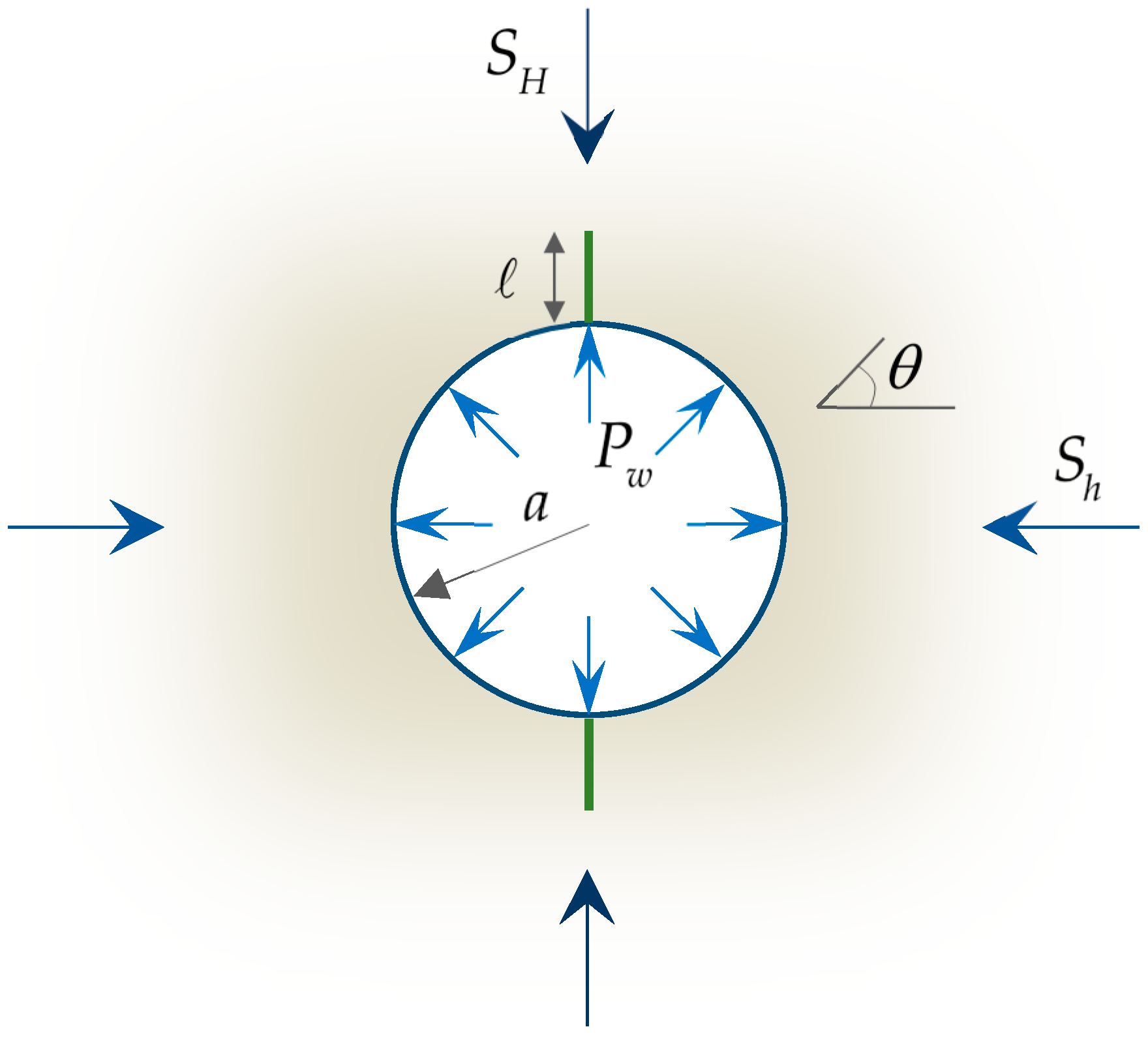
Figure A2.
Verification of stress intensity factor.

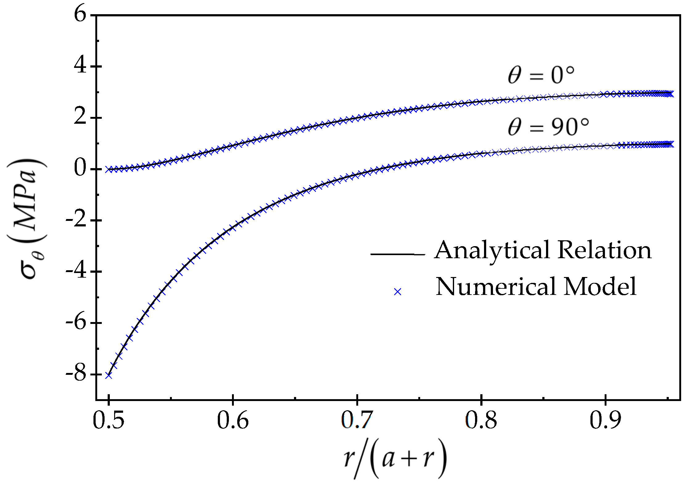
In another part of numerical model verification, we make a comparison between the circumferential stress around the wellbore gained from the FEM with the circumferential stress gained from the Kirsch’s analytical relations. For the circular wellbore shown in Figure A1, the circumferential stress around the wellbore is obtained from Equation (A5) [43]:
The comparison of the stresses obtained from the numerical model with the stresses obtained from the analytical relationship for two different directions is given in Figure A3. Again, good agreement between the two models is observed.
Figure A3.
Verification of circumferential stress around the wellbore.
References
- Hubbert, M.K.; Willis, D.G. Mechanics of hydraulic fracturing. Trans. AIME 1957, 210, 153–168. [Google Scholar] [CrossRef]
- Haimson, B.; Fairhurst, C. Initiation and extension of hydraulic fractures in rocks. Soc. Pet. Eng. J. 1967, 7, 310–318. [Google Scholar] [CrossRef]
- Aadnoy, B.S.; Angell-Olsen, F. Some effects of ellipticity on the fracturing and collapse behavior of a borehole. Int. J. Rock Mech. Min. Sci. Geomech. Abstr. 1995, 32, 621–627. [Google Scholar] [CrossRef]
- Akgun, F.; Yang, Z.; Crosby, D.G.; Rahman, S.S. Factors affecting hydraulic fracture initiation in high in-situ stress conditions: A wellbore stress modelling approach. In Proceedings of the SPE Annual Technical Conference and Exhibition, San Antonio, TX, USA, 5–8 October 1997; p. SPE-38631. [Google Scholar] [CrossRef]
- Zhang, X.; Jeffrey, R.G.; Bunger, A.P. Hydraulic fracture growth from a non-circular wellbore. In Proceedings of the ARMA US Rock Mechanics/Geomechanics Symposium, San Francisco, CA, USA, 26–29 June 2011; p. ARMA-11. [Google Scholar]
- Han, H.X.; Yin, S.; Aadnoy, B.S. Impact of elliptical boreholes on in situ stress estimation from leak-off test data. Pet. Sci. 2018, 15, 794–800. [Google Scholar] [CrossRef]
- Liu, C.; Zhang, D.; Zhao, H.; Li, M.; Song, Z. Experimental study on hydraulic fracturing properties of elliptical boreholes. Bull. Eng. Geol. Environ. 2022, 81, 18. [Google Scholar] [CrossRef]
- Jolfaei, S.; Lakirouhani, A. Initiation Pressure and Location of Fracture Initiation in Elliptical Wellbores. Geotech. Geol. Eng. 2023, 41, 4487–4506. [Google Scholar] [CrossRef]
- Ito, T.; Hayashi, K. Physical background to the breakdown pressure in hydraulic fracturing tectonic stress measurements. Int. J. Rock Mech. Min. Sci. Geomech. Abstr. 1991, 28, 285–293. [Google Scholar] [CrossRef]
- Garagash, D.; Detournay, E. An analysis of the influence of the pressurization rate on the borehole breakdown pressure. Int. J. Solids Struct. 1997, 34, 3099–3118. [Google Scholar] [CrossRef]
- Jin, X.; Shah, S.N.; Roegiers, J.C.; Hou, B. Breakdown pressure determination-a fracture mechanics approach. In Proceedings of the SPE Annual Technical Conference and Exhibition, New Orleans, LA, USA, 30 September–2 October 2013. [Google Scholar] [CrossRef]
- Lakirouhani, A.; Bunger, A.; Detournay, E. Modeling initiation of hydraulic fractures from a wellbore. In Proceedings of the ISRM International Symposium-Asian Rock Mechanics Symposium, Tehran, Iran, 24–26 November 2008; pp. 1101–1108. [Google Scholar]
- Bunger, A.P.; Lakirouhani, A.; Detournay, E. Modelling the effect of injection system compressibility and viscous fluid flow on hydraulic fracture breakdown pressure. In Proceedings of the ISRM International Symposium on In-Situ Rock Stress, Beijing, China, 25–27 August 2010; pp. ISRM–ISRS. [Google Scholar]
- Lakirouhani, A.; Jolfaei, S. Hydraulic fracturing breakdown pressure and prediction of maximum horizontal in situ stress. Adv. Civ. Eng. 2023, 2023, 8180702. [Google Scholar] [CrossRef]
- Haimson, B.C.; Zhao, Z. Effect of borehole size and pressurization rate on hydraulic fracturing breakdown pressure. In Proceedings of the ARMA US Rock Mechanics/Geomechanics Symposium, Norman, Oklahoma, 10–12 July 1991; p. ARMA–91. [Google Scholar]
- Schmitt, D.R.; Zoback, M.D. Diminished pore pressure in low-porosity crystalline rock under tensional failure: Apparent strengthening by dilatancy. J. Geophys. Res. Solid Earth 1992, 97, 273–288. [Google Scholar] [CrossRef]
- Schmitt, D.R.; Zoback, M.D. Infiltration effects in the tensile rupture of thin walled cylinders of glass and granite: Implications for the hydraulic fracturing breakdown equation. Int. J. Rock Mech. Min. Sci. Geomech. Abstr. 1993, 30, 289–303. [Google Scholar] [CrossRef]
- Zhao, Z.; Kim, H.; Haimson, B. Hydraulic fracturing initiation in granite. In Proceedings of the ARMA North America Rock Mechanics Symposium, Montreal, QC, Canada, 19–21 June 1996; p. ARMA–96. [Google Scholar]
- Lakirouhani, A.; Detournay, E.; Bunger, A.P. A reassessment of in situ stress determination by hydraulic fracturing. Geophys. J. Int. 2016, 205, 1859–1873. [Google Scholar] [CrossRef]
- Carter, B.J. Size and stress gradient effects on fracture around cavities. Rock Mech. Rock Eng. 1992, 25, 167–186. [Google Scholar] [CrossRef]
- Carter, B.J.; Lajtai, E.Z.; Yuan, Y. Tensile fracture from circular cavities loaded in compression. Int. J. Fract. 1992, 57, 221–236. [Google Scholar] [CrossRef]
- Leguillon, D. Strength or toughness? A criterion for crack onset at a notch. Eur. J. Mech. A/Solids 2002, 21, 61–72. [Google Scholar] [CrossRef]
- Leguillon, D.; Quesada, D.; Putot, C.; Martin, E. Prediction of crack initiation at blunt notches and cavities–size effects. Eng. Fract. Mech. 2007, 74, 2420–2436. [Google Scholar] [CrossRef]
- Lecampion, B. Modeling size effects associated with tensile fracture initiation from a wellbore. Int. J. Rock Mech. Min. Sci. 2012, 56, 67–76. [Google Scholar] [CrossRef]
- Chuprakov, D.; Melchaeva, O.; Prioul, R. Injection-sensitive mechanics of hydraulic fracture interaction with discontinuities. Rock Mech. Rock Eng. 2014, 47, 1625–1640. [Google Scholar] [CrossRef]
- Molnár, G.; Doitrand, A.; Estevez, R.; Gravouil, A. Toughness or strength? Regularization in phase-field fracture explained by the coupled criterion. Theor. Appl. Fract. Mech. 2020, 109, 102736. [Google Scholar] [CrossRef]
- Zhou, Z.L.; Guo, Y.T.; Zhang, X.; Huang, G.T. Fracture initiation from oval boreholes. J. Pet. Sci. Eng. 2022, 218, 110994. [Google Scholar] [CrossRef]
- Lakirouhani, A.; Jolfaei, S. Assessment of Hydraulic Fracture Initiation Pressure Using Fracture Mechanics Criterion and Coupled Criterion with Emphasis on the Size Effect. Arab. J. Sci. Eng. 2023, 49, 5897–5908. [Google Scholar] [CrossRef]
- Gerolymatou, E.; Petalas, A. In situ stress assessment based on width and depth of brittle borehole breakouts. In Recent Developments of Soil Mechanics and Geotechnics in Theory and Practice; Springer: Berlin/Heidelberg, Germany, 2020; pp. 297–319. [Google Scholar] [CrossRef]
- Lakirouhani, A.; Bahrehdar, M.; Medzvieckas, J.; Kliukas, R. Comparison of predicted failure area around the boreholes in the strike-slip faulting stress regime with Hoek-Brown and Fairhurst generalized criteria. J. Civ. Eng. Manag. 2021, 27, 346–354. [Google Scholar] [CrossRef]
- Haimson, B.C.; Song, I. Laboratory study of borehole breakouts in Cordova Cream: A case of shear failure mechanism. Int. J. Rock Mech. Min. Sci. Geomech. Abstr. 1993, 30, 1047–1056. [Google Scholar] [CrossRef]
- Haimson, B. Micromechanisms of borehole instability leading to breakouts in rocks. Int. J. Rock Mech. Min. Sci. 2007, 44, 157–173. [Google Scholar] [CrossRef]
- Meier, T.; Rybacki, E.; Reinicke, A.; Dresen, G. Influence of borehole diameter on the formation of borehole breakouts in black shale. Int. J. Rock Mech. Min. Sci. 2013, 62, 74–85. [Google Scholar] [CrossRef]
- Setiawan, N.B.; Zimmerman, R.W. Semi-analytical method for modeling wellbore breakout development. Rock Mech. Rock Eng. 2022, 55, 2987–3000. [Google Scholar] [CrossRef]
- Sahara, D.P.; Schoenball, M.; Gerolymatou, E.; Kohl, T. Analysis of borehole breakout development using continuum damage mechanics. Int. J. Rock Mech. Min. Sci. 2017, 97, 134–143. [Google Scholar] [CrossRef]
- Leriche, A.; Kalenchuk, K.; Diederichs, M.S. Estimation of In Situ Stress from Borehole Breakout at KGHM’s Victoria Project, Canada. In Proceedings of the 52nd U.S. Rock Mechanics/Geomechanics Symposium, Seattle, WA, USA, 17–20 June 2018. [Google Scholar]
- Xiang, Z.; Moon, T.; Oh, J.; Li, X.; Si, G.; Canbulat, I. Numerical investigation of borehole breakout and rock spalling based on strain energy criteria. Int. J. Rock Mech. Min. Sci. 2023, 171, 105587. [Google Scholar] [CrossRef]
- Babcock, E.A. Measurement of subsurface fractures from dipmeter logs. AAPG Bull. 1978, 62, 1111–1126. [Google Scholar] [CrossRef]
- Gough, D.I.; Bell, J.S. Stress orientations from borehole wall fractures with examples from Colorado, east Texas, and northern Canada. Can. J. Earth Sci. 1982, 19, 1358–1370. [Google Scholar] [CrossRef]
- Zoback, M.D.; Moos, D.; Mastin, L.; Anderson, R.N. Well bore breakouts and in situ stress. J. Geophys. Res. Solid Earth 1985, 90, 5523–5530. [Google Scholar] [CrossRef]
- Jolfaei, S.; Lakirouhani, A. Sensitivity analysis of effective parameters in borehole failure, using neural network. Adv. Civ. Eng. 2022. [Google Scholar] [CrossRef]
- Rummel, F. Fracture mechanics approach to hydraulic fracturing stress measurements. In Fracture Mechanics of Rock; Elsevier: Amsterdam, The Netherlands, 1987; p. 217. [Google Scholar]
- Jaeger, J.C.; Cook, N.G.; Zimmerman, R. Fundamentals of Rock Mechanics; John Wiley & Sons: New York, NY, USA, 2009. [Google Scholar]
Figure 1.
Problem geometry for elliptical wellbores.

Figure 2.
Problem geometry for breakout wellbores.
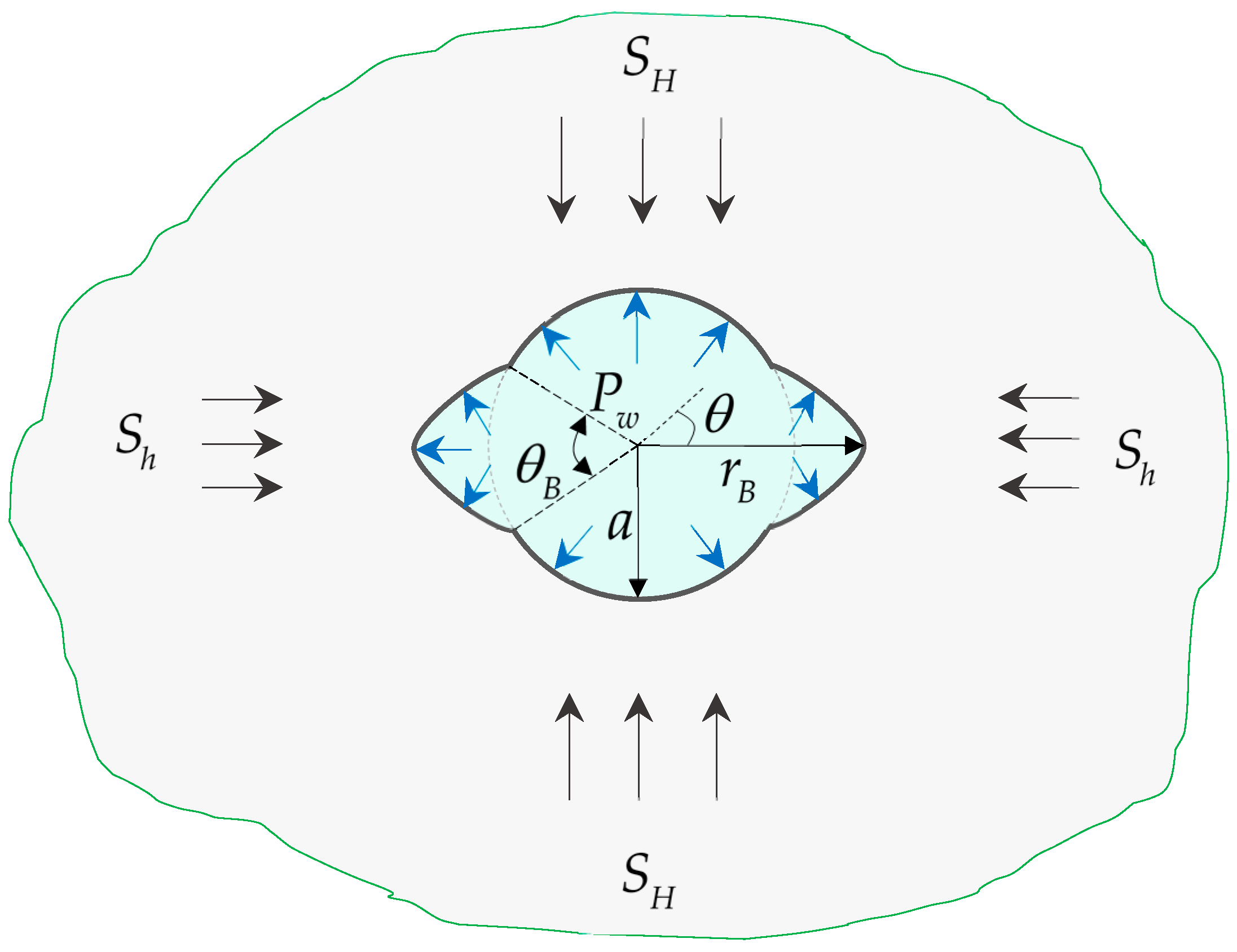
Figure 3.
Boundary conditions and finite-element mesh for elliptical wellbores.

Figure 4.
Boundary conditions and finite-element mesh for breakout wellbores.
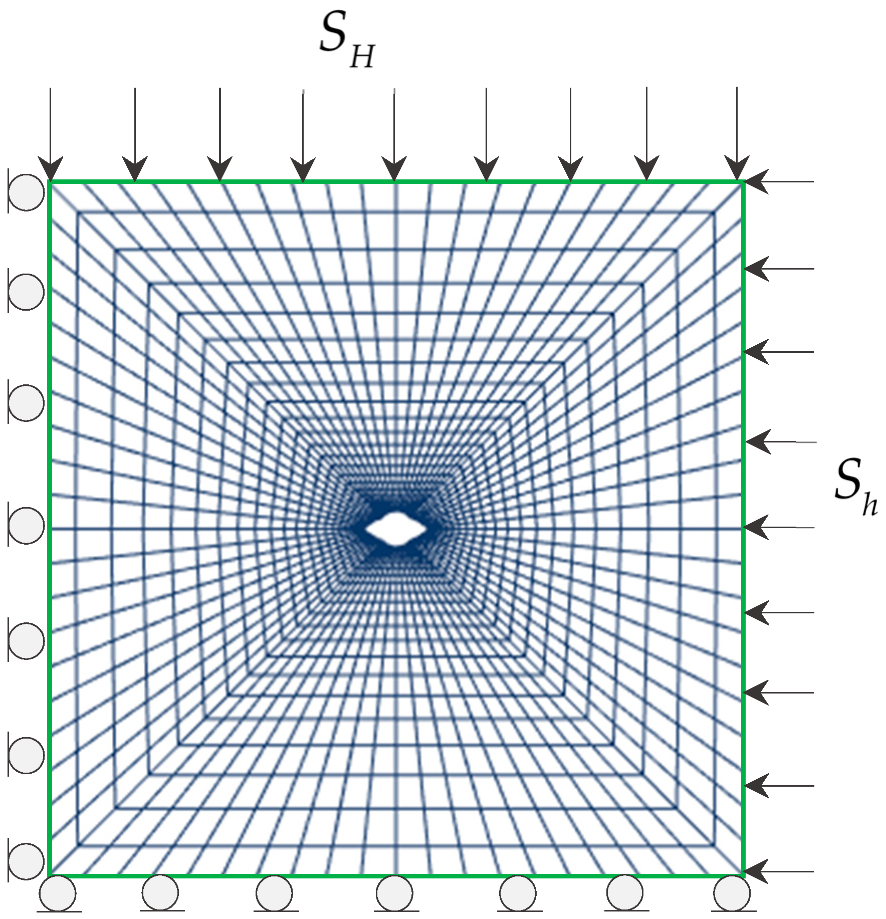
Figure 5.
Illustration of calculating the breakdown pressure: (a) cross-section of a breakout wellbore; (b) wellbore pressure versus crack length.
Figure 5.
Illustration of calculating the breakdown pressure: (a) cross-section of a breakout wellbore; (b) wellbore pressure versus crack length.
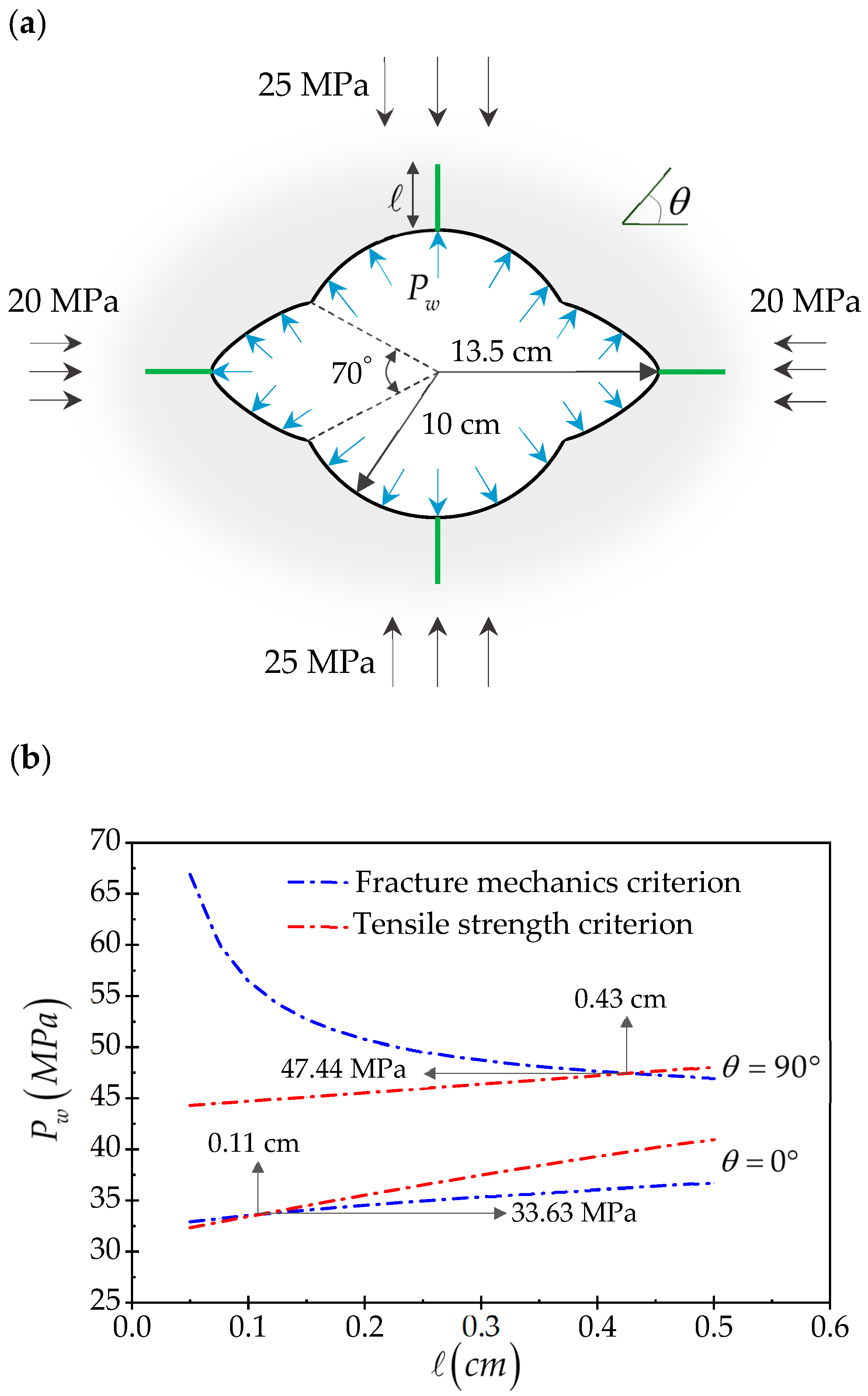
Figure 6.
Plot of breakdown pressure against the shape parameter for different values of dimensionless deviatoric stress.
Figure 6.
Plot of breakdown pressure against the shape parameter for different values of dimensionless deviatoric stress.
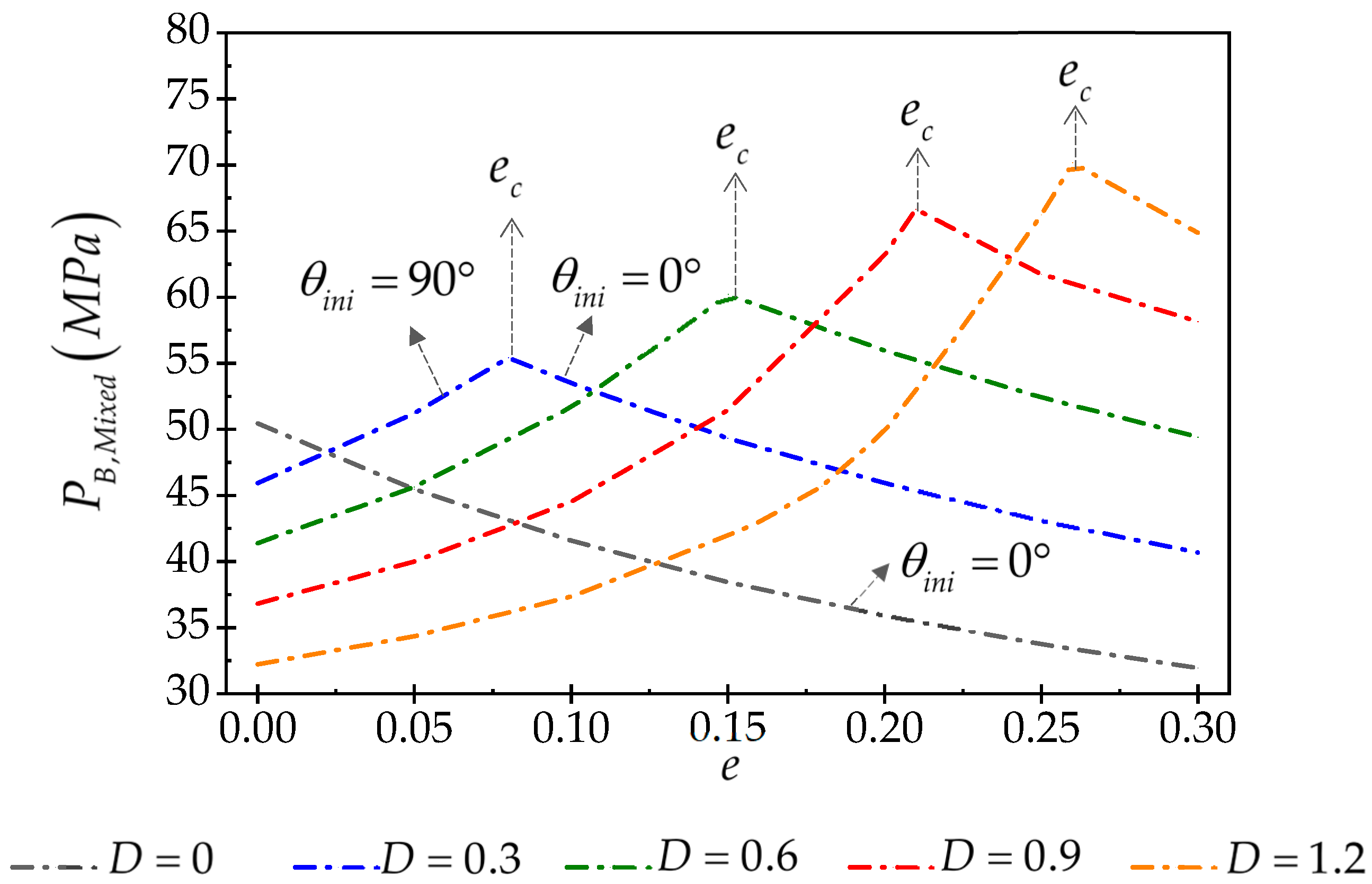
Figure 7.
Four series of wellbores with different sizes but the same shape parameters.

Figure 8.
Breakdown pressure obtained from the mixed criterion versus the minor axis of the ellipse for different shape parameters .
Figure 8.
Breakdown pressure obtained from the mixed criterion versus the minor axis of the ellipse for different shape parameters .
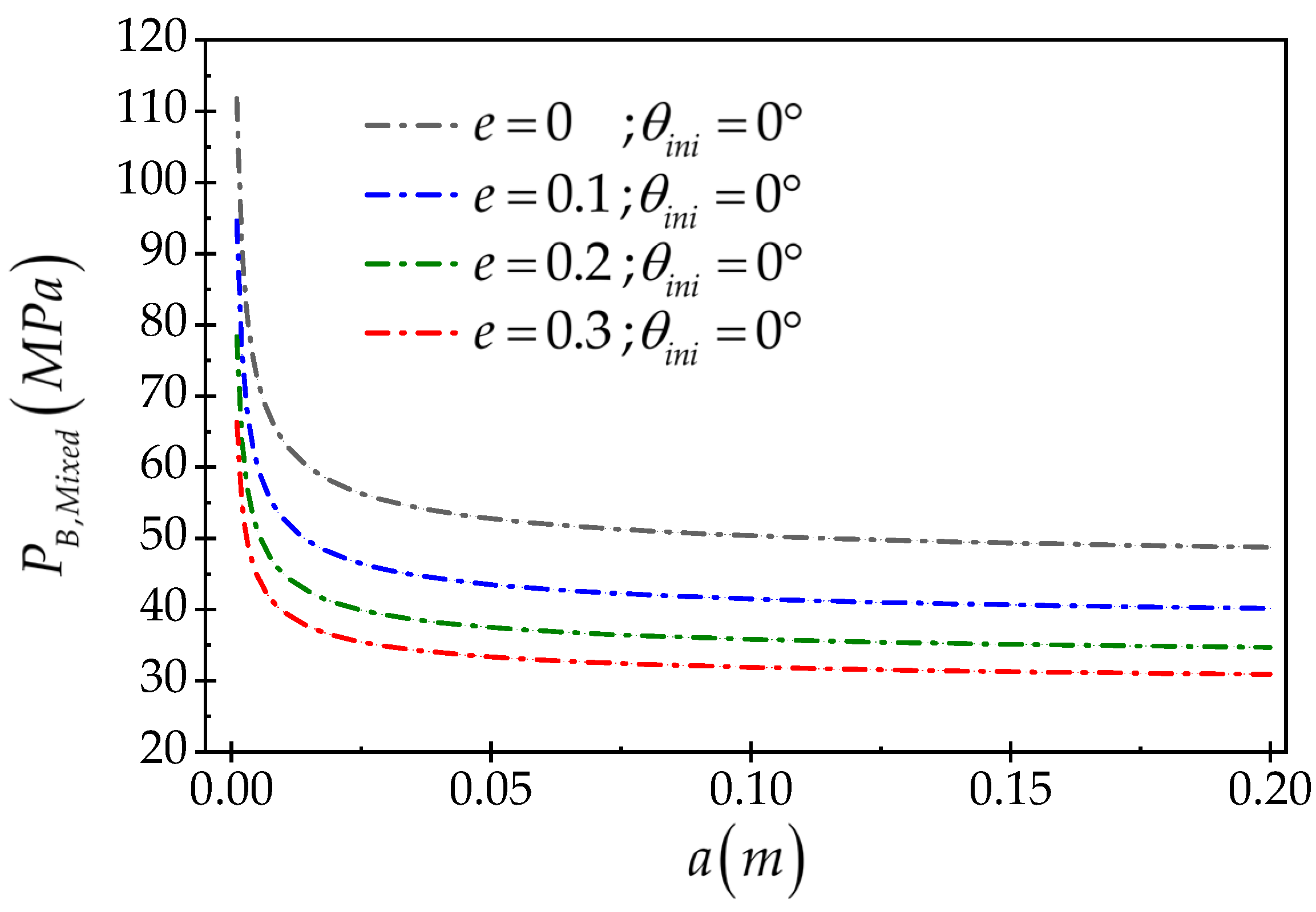
Figure 9.
Dimensionless breakdown pressure versus the dimensionless size of the wellbore (made dimensionless by relation (8)) .
Figure 9.
Dimensionless breakdown pressure versus the dimensionless size of the wellbore (made dimensionless by relation (8)) .

Figure 10.
Dimensionless fracture initiation length versus the .

Figure 11.
Breakdown pressure versus the minor axis of the ellipse for and .
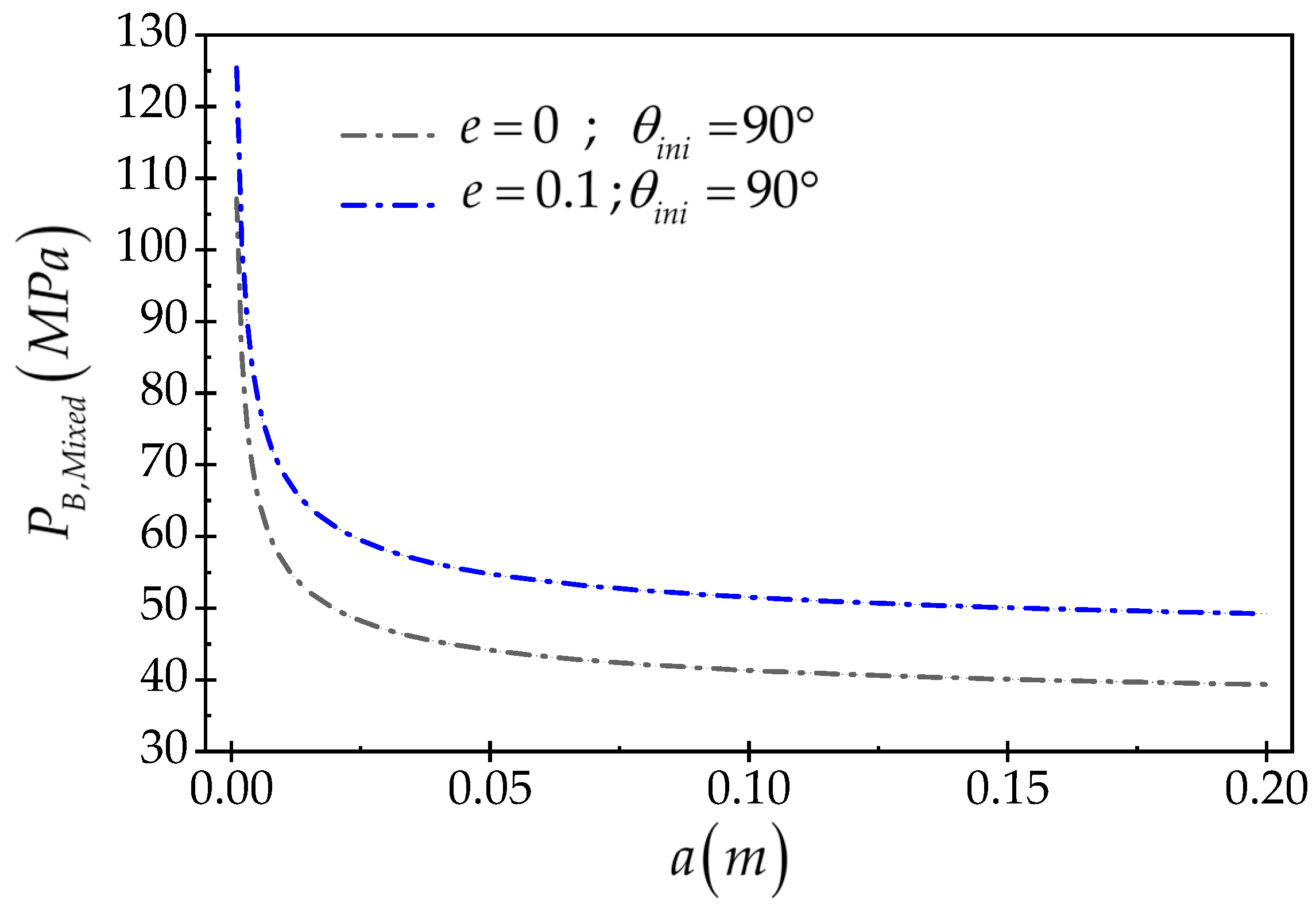
Figure 12.
Breakdown pressure versus the minor axis of the ellipse for and .
Figure 13.
Dimensionless breakdown pressure versus the minor axis of the ellipse (made dimensionless by relation (10)) .
Figure 13.
Dimensionless breakdown pressure versus the minor axis of the ellipse (made dimensionless by relation (10)) .
Figure 14.
Dimensionless breakdown pressure versus the minor axis of the ellipse (made dimensionless by relation (11)) .
Figure 14.
Dimensionless breakdown pressure versus the minor axis of the ellipse (made dimensionless by relation (11)) .
Figure 15.
Dimensionless fracture initiation length versus .
Figure 16.
Dimensionless breakdown pressure versus (made dimensionless by relation (11)).
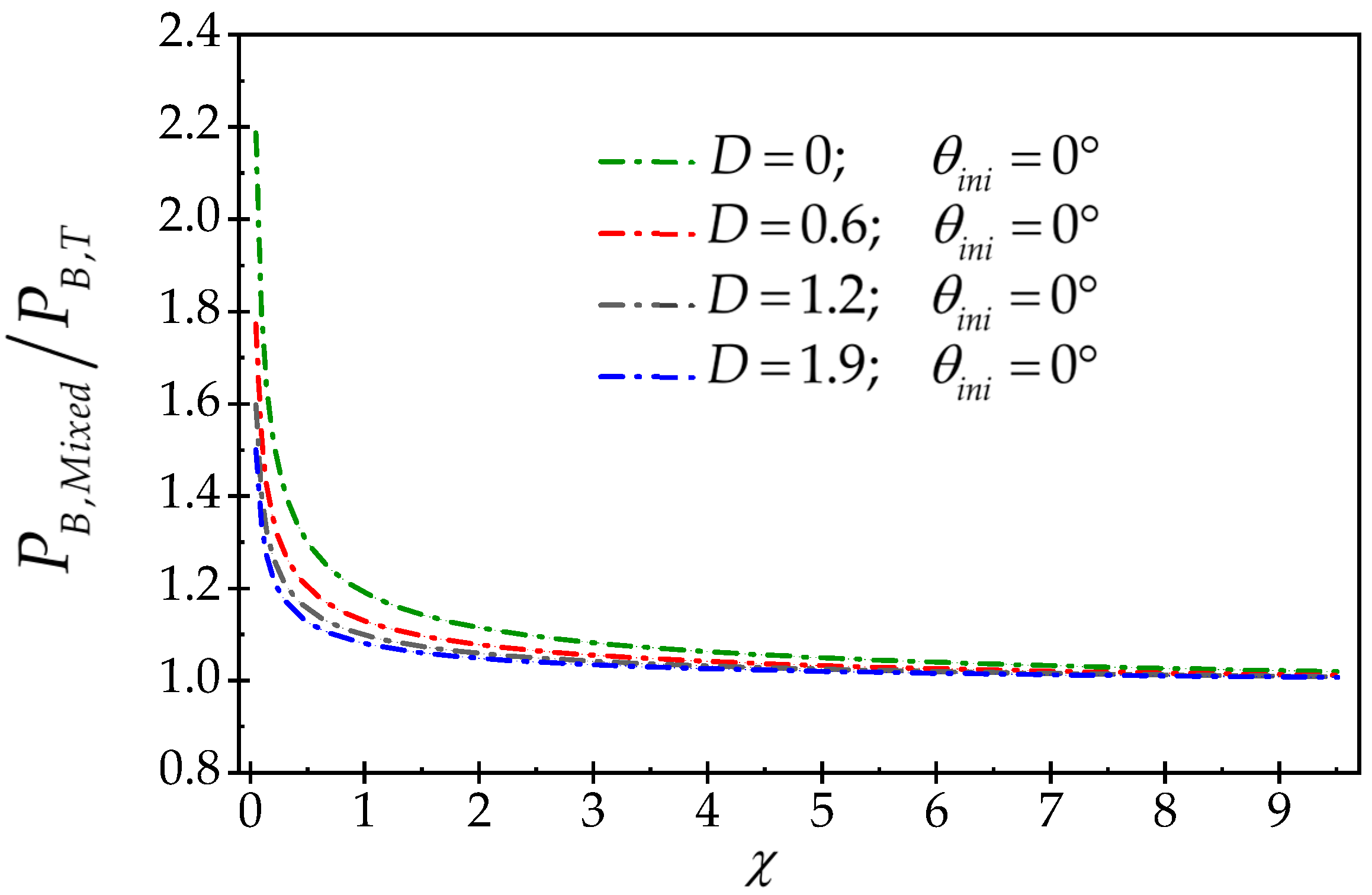
Figure 17.
Dimensionless fracture initiation length versus .

Figure 18.
Geometry of breakout wellbores.

Figure 19.
Scaled breakdown pressure, .
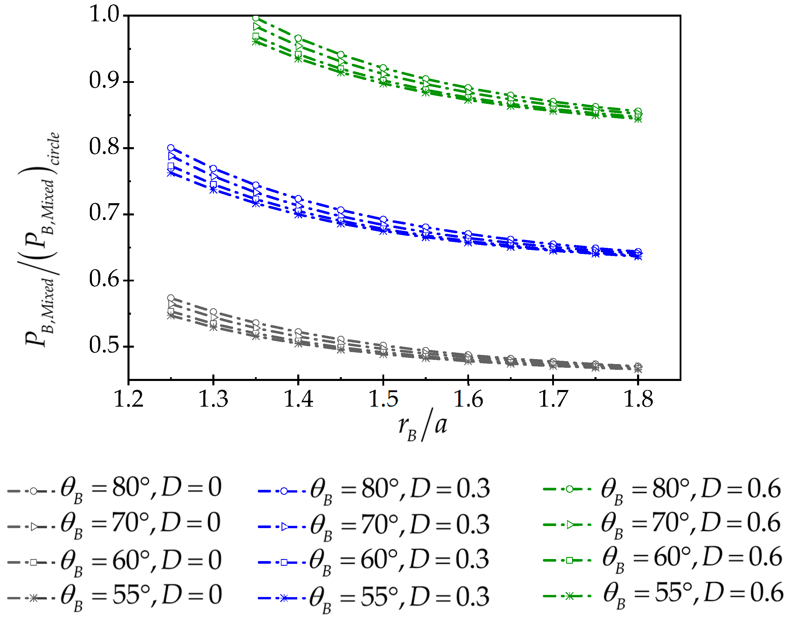
Figure 20.
Scaled breakdown pressure, .

Figure 21.
Scaled breakdown pressure versus breakout width, .

Figure 22.
Scaled breakdown pressure versus breakout width, .
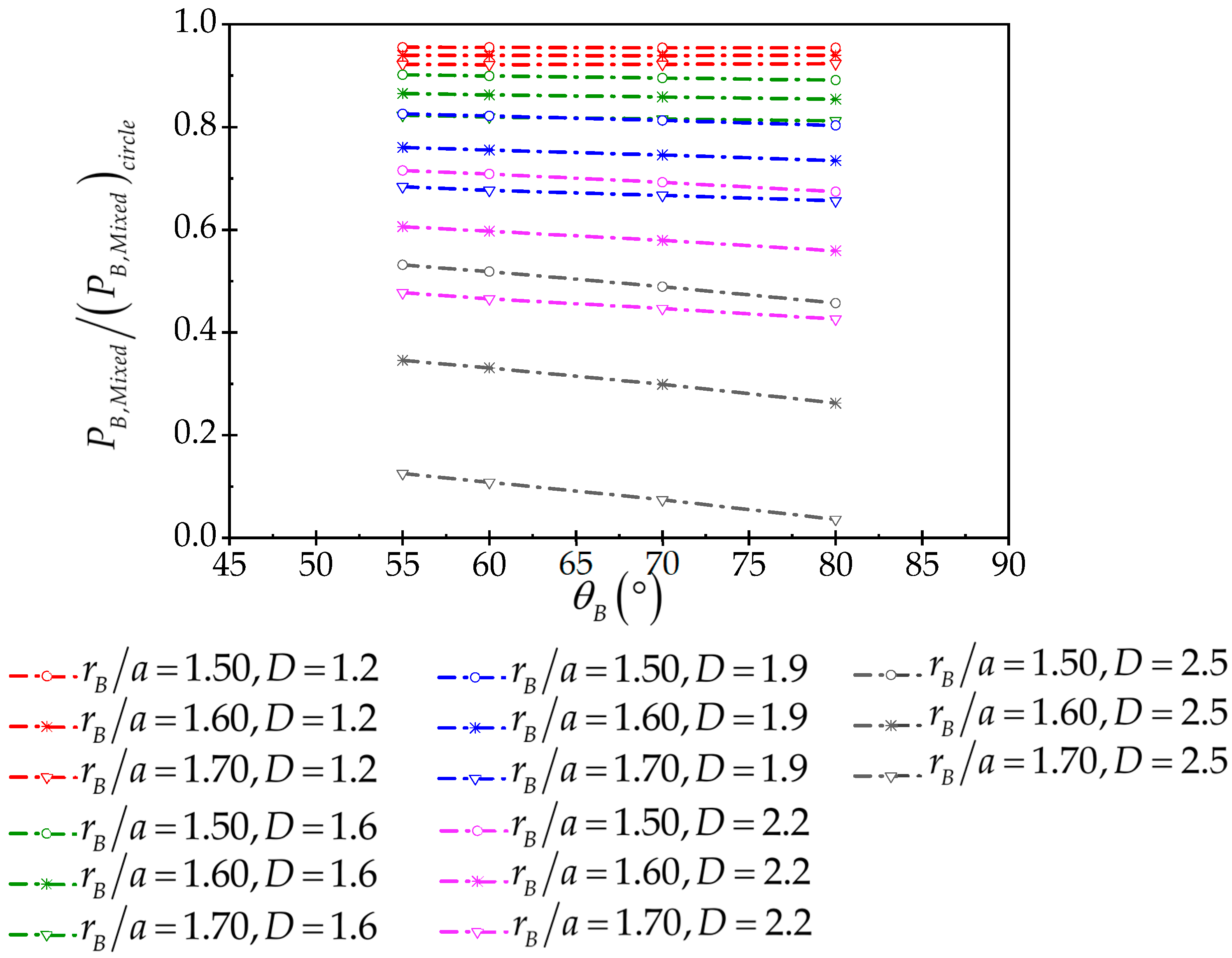
Figure 23.
Scaled breakdown pressure versus .
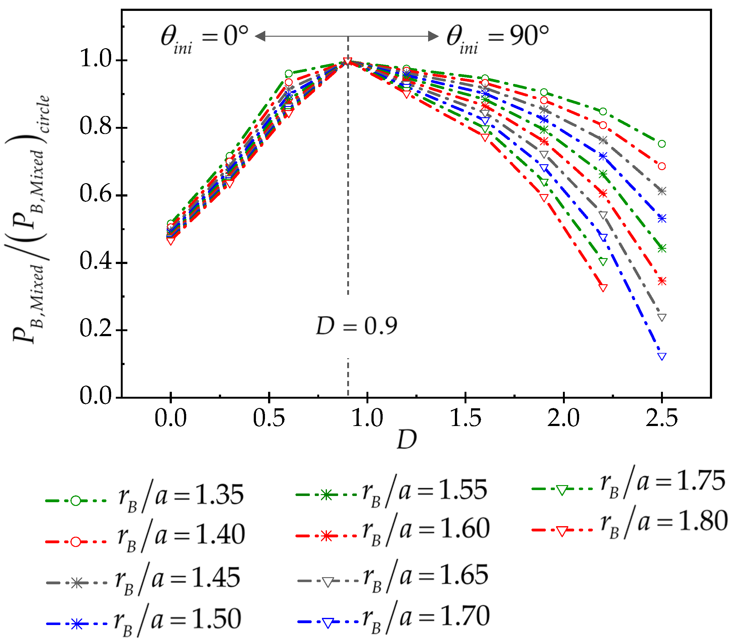
Figure 24.
Scaled breakdown pressure versus .
Figure 25.
Cross section of breakout wellbores with the same breakout depth and width but different diameters, a: , b: , c: , d: , e: , f: .
Figure 25.
Cross section of breakout wellbores with the same breakout depth and width but different diameters, a: , b: , c: , d: , e: , f: .
Figure 26.
Dimensionless breakdown pressure versus dimensionless wellbore radius.

Figure 27.
Dimensionless fracture initiation length versus


Table 1.
Characteristics of rock materials.
| --- | |||
| 59 | 0.25 | 8 | 1.16 |
Disclaimer/Publisher’s Note: The statements, opinions and data contained in all publications are solely those of the individual author(s) and contributor(s) and not of MDPI and/or the editor(s). MDPI and/or the editor(s) disclaim responsibility for any injury to people or property resulting from any ideas, methods, instructions or products referred to in the content. |
© 2024 by the authors. Licensee MDPI, Basel, Switzerland. This article is an open access article distributed under the terms and conditions of the Creative Commons Attribution (CC BY) license (https://creativecommons.org/licenses/by/4.0/).
Share and Cite
MDPI and ACS Style
Jolfaei, S.; Lakirouhani, A. Impact of Wellbore Cross-Sectional Elongation on the Hydraulic Fracturing Breakdown Pressure and Fracture Initiation Direction. Processes 2024, 12, 848. https://doi.org/10.3390/pr12050848
AMA Style
Jolfaei S, Lakirouhani A. Impact of Wellbore Cross-Sectional Elongation on the Hydraulic Fracturing Breakdown Pressure and Fracture Initiation Direction. Processes. 2024; 12(5):848. https://doi.org/10.3390/pr12050848
Chicago/Turabian StyleJolfaei, Somaie, and Ali Lakirouhani. 2024. "Impact of Wellbore Cross-Sectional Elongation on the Hydraulic Fracturing Breakdown Pressure and Fracture Initiation Direction" Processes 12, no. 5: 848. https://doi.org/10.3390/pr12050848
Note that from the first issue of 2016, this journal uses article numbers instead of page numbers. See further details here.