Dispersion Performance of Carbon Nanotubes on Ultra-Light Foamed Concrete

1
School of Materials Science and Engineering, Inner Mongolia University of Technology, Hohhot 010051, China
2
Department of Mechanical and Electrical Engineering, Inner Mongolia Technical College of Construction, Hohhot 010070, China
*
Author to whom correspondence should be addressed.
Processes 2018, 6(10), 194; https://doi.org/10.3390/pr6100194
Submission received: 29 September 2018
/
Revised: 10 October 2018
/
Accepted: 12 October 2018
/
Published: 17 October 2018
(This article belongs to the Special Issue Transport of Fluids in Nanoporous Materials)
Abstract
:This study investigates the effect of carbon nanotube (CNT) dispersion on the mechanical properties and microstructures of ultra-light foamed concrete. A type of uniform and stable CNT dispersion solution is obtained by adding nano-Ce(SO4)2. Results show that CNT dispersion increases the compressive and breaking strengths of foamed concrete. CNTs play a nuclear role in the crystallization of C–S–H, and CNT dispersion effectively promotes the grain growth of C–S–H. The effect of CNT dispersion on the compressive and breaking strengths of foamed concrete is predicted through simulation.
1. Introduction
Foamed concrete is typically composed of cement, fly ash, foam, and water. The foam in the concrete generates a large number of air pores with diameters ranging from 1 mm to 3 mm. Consequently, the density of foamed concrete generally ranges from 200 kg/m3 to 2000 kg/m3 [1]. In particular, low-density foamed concrete (≤300 kg/m3) is regarded as ultra-light foamed concrete. Substantial theoretical research and engineering experience suggest that ultra-light foamed concrete is unstable [2]. The inevitable instability of ultra-light foamed concrete usually results in poor mechanical properties, such as compressive and breaking strengths, which limit the application of this material.
Several experimental investigations evaluated the compressive and breaking strengths of foamed concrete. Furthermore, an increasing number of studies attempted to enhance the compressive and breaking strengths of ultra-light foamed concrete by introducing various fibers [3,4,5,6]. In recent years, researchers have proven that the introduction of carbon nanotubes (CNTs) effectively increases the compressive and breaking strengths of concrete/foamed concrete, and this effect is influenced by CNT dispersion [7,8,9,10]. Achieving a uniform distribution of CNTs in cement paste, which is key to enhancing the compressive and breaking strengths of foamed concrete, is complicated by their tendency to agglomerate [7].
Previous studies have attempted to increase CNT dispersion by using various methods, including mechanical processing and surface modification. An increasing number of researchers have employed surface modification methods [11,12,13,14], such as HCl/H2SO4/HNO treatment and thermal chemical vapor deposition. However, the strong acids used in these CNT dispersion methods can damage concrete/foamed concrete. Conversely, reactions between the organic matter in CNT dispersion and the chemical substances in foamed concrete hinder the growth of the foamed concrete particles. Consequently, the applications of these traditional methods of CNT dispersion in concrete/foamed concrete are limited. This limitation explains the lack of investigations on concrete and foamed concrete materials.
In the present study, we introduced inorganic matter nano-Ce(SO4)2 to realize high-performance CNT dispersion. The effect of nano-Ce(SO4)2 on the dispersion, structure, and surface of the prepared CNTs was determined. This study aimed to develop a new type of CNT dispersion method for enhancing the mechanical properties and microstructure of ultra-light foamed concrete. Moreover, modeling and simulation issues should be considered in order to develop a thorough approach, and thus make well-informed decisions [15,16]. We also simulated the effect of CNT dispersion on the compressive and breaking strengths of foamed concrete.
2. Materials and Test Methods
2.1. Materials
The following materials were used in the experiments: cement with a compressive strength of 42.5 MPa after 28 days (Hohhot, China), fly ash (L2 dry ash), naphthalene water reducer (industrial grade, Shanghai, China), FeCl3 (industrial grade, Hangzhou, China), H2O2 (27.5%, Beijing, China), calcium stearate (analytical reagent, Beijing, China), multi-walled CNTs (diameter of 10–30 nm and length of 5–15 µm, Beijing, China), nano-Ce(SO4)2 (analytical reagent, Shanghai, China), and water (tap water, Hohhot, China).
Transmission electron microscopy (TEM, Hillsboro, OR, USA) images of the CNTs are shown in Figure 1. Figure 1a shows that the CNTs present serious agglomerations, and Figure 1b illustrates that the CNTs are indeed multi-walled. The density of foamed concrete and the content (0.20–0.24 g) of CNTs added were varied. The physical and mechanical properties of the multi-walled CNTs are listed in Table 1.
2.2. Preparation of CNT Dispersion
In a beaker, a certain quantity of CNTs and tap water were mixed and stirred with a glass rod for 5 min until complete dissolution. The solution was ultrasonically cleaned, and the temperature was controlled at 40 °C, considering that solution temperature affects CNT dispersion. Specifically, the structure of CNTs is damaged by high temperatures [17,18,19,20]. After 20 min of ultrasound, different contents of nano-Ce(SO4)2 were added, and ultrasonic was performed at 99 W for 1 h to prepare a homogeneous CNT dispersion solution [21]. The different contents of CNT dispersion solution and the corresponding foamed concretes are shown in Table 2.
A type of CNT dispersion solution is prepared in Table 3. Three beakers (A, B, and C), each containing 50 mL of water, were prepared. Then, 0.3 wt% CNTs were added into each of the three beakers [22]. Finally, 0.3 wt% nano-Ce(SO4)2 was added to beaker B, and 0.6 wt% nano-Ce(SO4)2 was added to beaker C.
2.3. Characteristics of CNT Dispersion
CNT dispersion solution was prepared by dissolving CNTs (0.1, 0.2, 0.3, 0.4, and 0.5 wt%) and nano-Ce(SO4)2 (0.3 and 0.6 wt%) in water at room temperature. After approximately 6–7 h, CNT particles settled in the bottom of the beaker completely, based on visual inspection. The dispersion property of the CNTs in the solution was observed under a FEI Talos200X transmission electron microscope (Hillsboro, OR, USA). In addition, CNT dispersion was analyzed by obtaining the test absorption spectra using a UV-1700 spectrophotometer (Tokyo, Japan). Absorbance spectra refer to the distribution of CNTs or to the settlement of CNT particles in the solution.
2.4. Preparation of Foamed Concrete and CNT/Foamed Concrete
Ordinary Portland cement, fly ash, and calcium stearate were mixed with self-made foam concrete mixing equipment for 2–3 min. The water/CNT dispersion solution was added and then stirred for 2–3 min to form foamed concrete as a thick liquid, and the water temperature was controlled at approximately 35 °C. Finally, FeCl3 and H2O2 were added successively and then stirred at a high speed for 30 s. After stirring, the liquid was poured in a mold and then demolded after 24 h. The sample was prepared into two standard test pieces with dimensions of 100 mm × 100 mm × 100 mm and 400 mm × 100 mm × 100 mm, which were then stored in the standard curing room for 7 and 28 days, respectively.
2.5. Characteristic of CNT Dispersion in Foamed Concrete
A CNT foamed concrete block was prepared by adding the CNT dispersion solution into foamed concrete paste (Table 2). The microstructure of the CNT foamed concrete was observed under a QUANTA FEG 650 electron scanning microscope (SEM) to evaluate CNT dispersion.
2.6. Measurement Methods
(1) Dry density test was performed in accordance with the provisions in foamed concrete of JG/T266-2011 (the construction industry standard of the People’s Republic of China), which is promulgated by the ministry of housing and urban-rural development of the People’s Republic of China.
(2) Compressive strength test was performed in accordance with the provisions in the foamed concrete of JG/T266-2011 (the construction industry standard of the People’s Republic of China), which is promulgated by the ministry of housing urban-rural development of the People’s Republic of China.
(3) Breaking strength test was performed in accordance with the provisions in the foamed concrete of JG/T266-2011 (the construction industry standard of the People’s Republic of China), which is promulgated by the ministry of housing and urban-rural development of the People’s Republic of China.
(4) QUANTA FEG 650 electron scanning microscope was used for morphological observation (Hillsboro, OR, USA).
(5) The solution was sonicated using a SK250LH ultrasonic cleaner (Shanghai, China).
(6) CNT dispersion was observed using a FEI Talos200X transmission electron microscope (Hillsboro, OR, USA).
(7) Absorbance spectra were tested using a UV-1700 spectrophotometer (Tokyo, Japan).
(8) Pro/Engineer (Pro-E) software (Parametric Technology Corporation, Boston, MA, USA) is an entity modeling system that uses parametric design based on physical characteristics. It was used for the modeling and simulation of foamed concrete.
3. Results and Discussion
3.1. Uniformity of CNT Dispersion
The effects of different contents of nano-Ce(SO4)2 on CNT dispersion are reported in this section. Figure 2, Figure 3 and Figure 4 display the effects of the nano-Ce(SO4)2 values on CNT dispersion and surface.
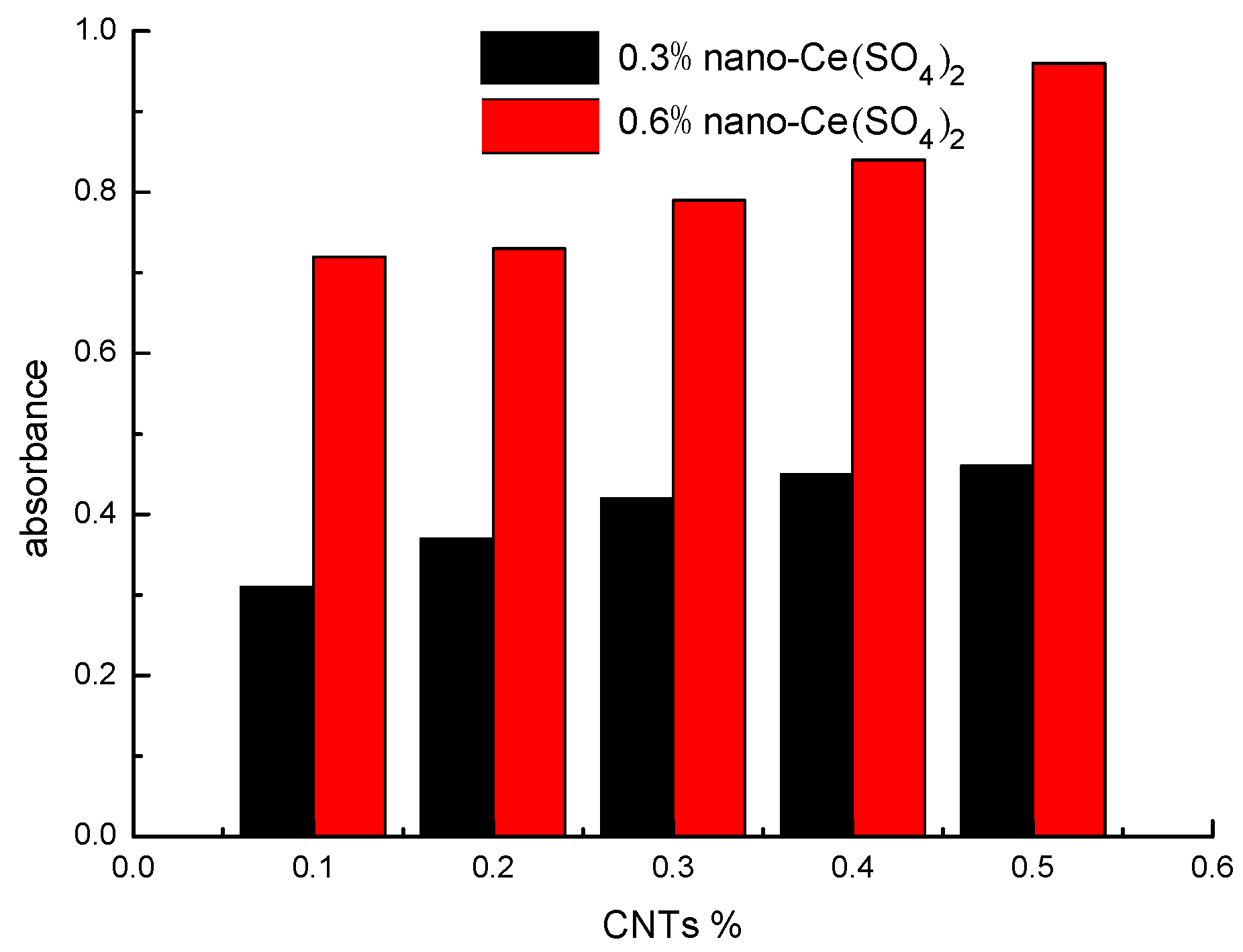
An important parameter influencing CNT dispersion is the degree of uniformity of particle distribution in solution. The degree of CNT dispersion properties, including particle size, degree of uniformity of particle distribution in solution, and dispersion stability, can be determined based on the absorbance [23,24]. CNT dispersion is analyzed by detecting absorbance. Ten types of CNT dispersion solutions (S1-1, S1-2, S2-1, S2-2, S3-1, S3-2, S4-1, S4-2, S5-1, and S5-2) are prepared (Table 2). These CNT dispersion solutions are subjected to ultrasound for 0.5 h and then allowed to stand for 2 h. The absorbance the solutions is then obtained with a UV-1700 ultraviolet spectrophotometer (Figure 2). As reported in previous studies [23,24], higher absorbance values indicate better dispersion. Figure 2 shows that the increase in absorbance spectra with increasing CNT content from 0.1 wt% to 0.5 wt% is due to the dispersion of CNT particles by 0.3% nano-Ce(SO4)2 in the solution, approximately 0.31–0.46%. The histograms of 0.3% nano-Ce(SO4)2 and 0.6% nano-Ce(SO4)2 show the same patterns, and the increasing range of absorbance spectra with 0.6% nano-Ce(SO4)2 is 0.72–0.96%. This result can be explained by the presence of large CNT aggregates in the solution when 0.3% nano-Ce(SO4)2 is added. When nano-Ce(SO4)2 is continuously added into the solution, the newly increased 0.3% nano-Ce(SO4)2 has a greater tendency to enhance the dispersion of CNT particles in the solution. The absorbance spectra of CNT dispersion increase by 132.26% (0.1% CNTs), 97.30% (0.2% CNTs), 88.10% (0.3% CNTs), 86.67% (0.4% CNTs), and 108.7% (0.5% CNTs) after adding 0.6% nano-Ce(SO4)2 relative to 0.3% nano-Ce(SO4)2. This behavior indicates that the remaining aggregate CNTs are dispersed effectively by the newly increased 0.3% nano-Ce(SO4)2.
Another important parameter of the CNT dispersion is the dispersion stability. The absorbance spectra of the CNT dispersions with 0.3% nano-Ce(SO4)2 and 0.6% nano-Ce(SO4)2 are shown in Figure 3a,b. Figure 3a shows that the absorbance spectra decrease slowly from 1 h to 6 h, indicating that the CNT particles are setting slowly. Then, the spectra almost become constant from 7 h to 12 h. In particular, the absorbance spectra of all the specimens are almost overlapping from 7 h to 12 h, indicating that the CNT particles are completely set. This result is consistent with the visual inspection result that the CNT particles are completely set at about 6 h later. The absorbance spectra of the CNT dispersion solutions with 0.3% nano-Ce(SO4)2 and 0.6% nano-Ce(SO4)2 almost coincide, except for two results described below. First, the CNT particles with 0.6% nano-Ce(SO4)2 set completely about 1 h later than those with 0.3% nano-Ce(SO4)2. Second, all of the absorbance spectra of 0.6% nano-Ce(SO4)2 are higher than those of 0.3% nano-Ce(SO4)2 at the same time. Consequently, the setting behavior and dispersion stability of the CNT particles are prevented by the addition of 0.3% nano-Ce(SO4)2 into the CNT dispersion solution.
Figure 3a,b show that the absorbance spectra are almost overall declined (from S1-1, S2-1 to S5-1, from S1-2, S2-2, to S5-2). Nevertheless, the absorbance spectra of S1-1 basically overlap with those of S2-1, and the absorbance spectra of S1-1 at 3, 5, and 9 h are below those of S2-1. This result indicates that the absorbance spectra (0.3% nano-Ce(SO4)2) are unstable when 0.1% and 0.2% CNTs are added.
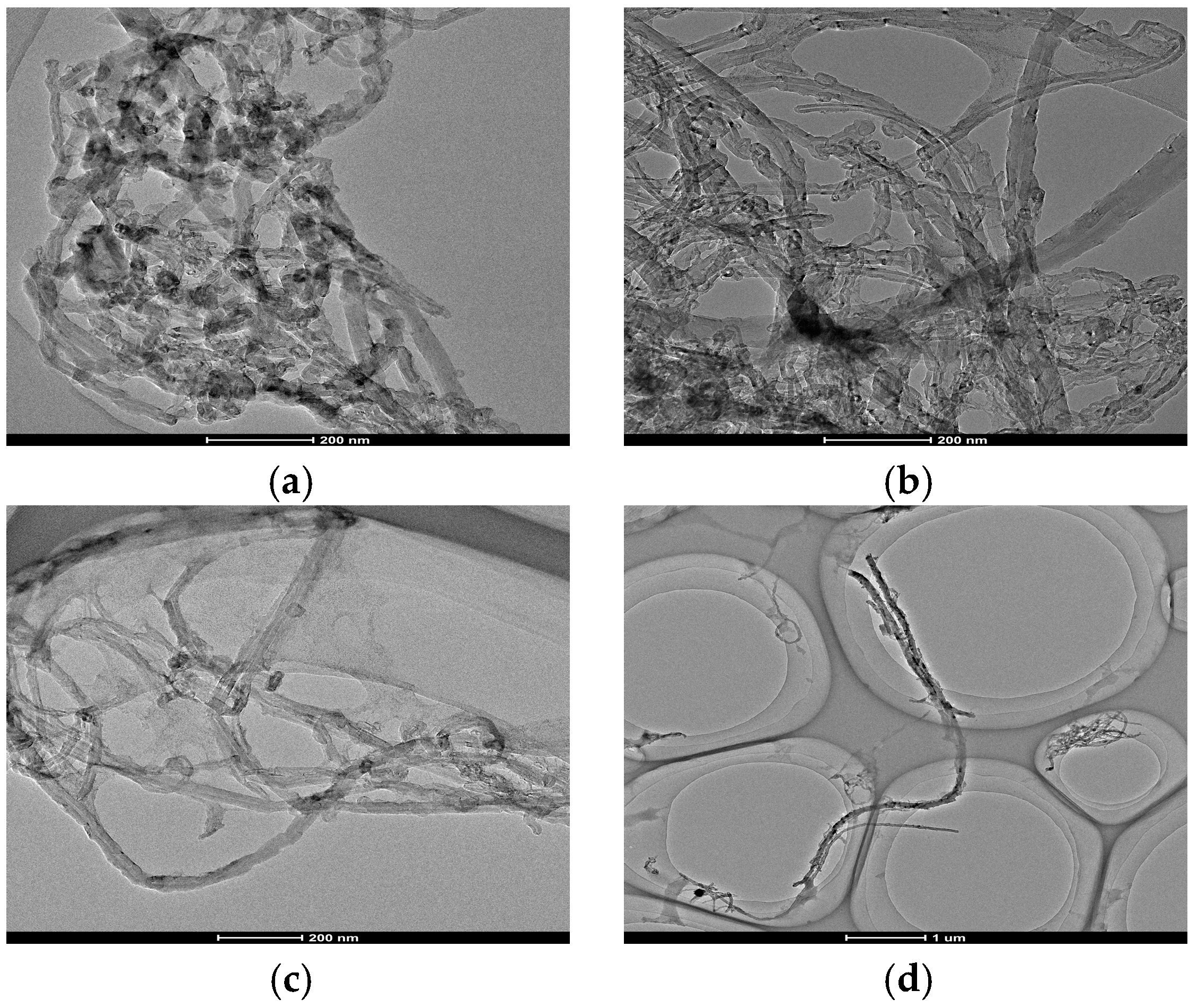
A type of CNT dispersion solution is prepared as described in Table 3 to investigate the impact of different contents of nano-Ce(SO4)2 on CNT dispersion. Figure 4 shows the TEM images of the CNTs obtained with FEI Talos200X (Hillsboro, OR, USA). Figure 4a,b show that the increased 0.3% nano-Ce(SO4)2 can disperse the aggregates of CNTs. Figure 4b,c displays that the newly increased 0.3% nano-Ce(SO4)2 can disperse the aggregates of CNTs in beaker B, which correspond to the results in Figure 2 and Figure 3. Figure 4d shows that single CNTs can be obtained from aggregates of CNTs when the content of nano-Ce(SO4)2 is increased to 0.6%. These results indicate that nano-Ce(SO4)2 is a significant factor affecting the CNT dispersion of foamed concrete.
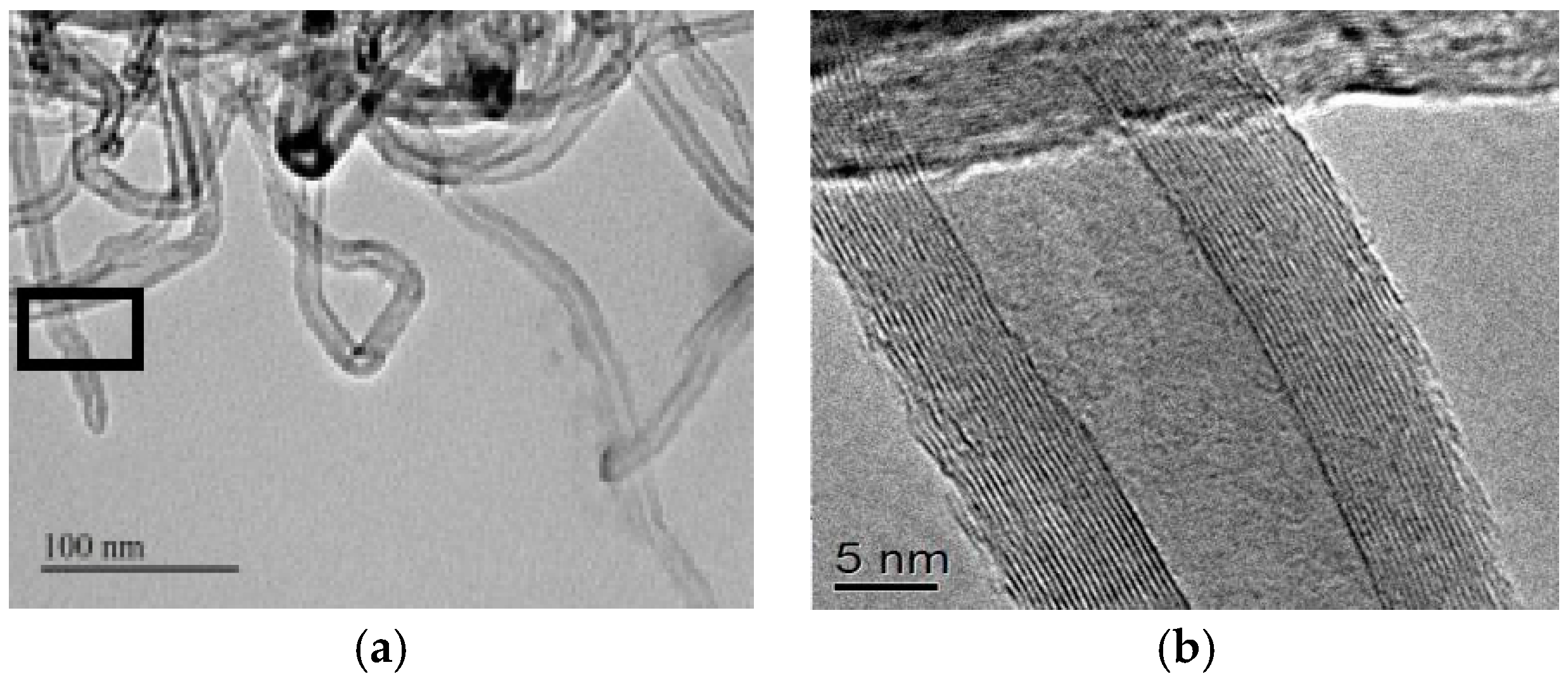
CNT dispersion is determined by the species, diameter, and morphology of CNTs, and by the dispersing agent [25]. The results above show that nano-Ce(SO4)2, which can be adsorbed onto the surface of CNTs by ultrasound, plays a major role in CNT dispersion. Thus, nano-Ce(SO4)2 shows “superactivity” with the action of ultrasonic wave and prevents the aggregation of CNTs. Once nano-Ce(SO4)2 is adsorbed onto the surface of CNTs, it can also adhere stably onto the surface of CNTs (Figure 5). A detailed description of nano-Ce(SO4)2 distribution on the surface of CNTs is shown in the two TEM images in Figure 5. As illustrated in Figure 5a,b, the surface of CNTs forms a saw-tooth shape with non-uniform thickness because nano-Ce(SO4)2 is adsorbed irregularly onto the surface of CNTs. In addition, the excellent binding force between CNTs and foamed concrete is obtained due to the saw-tooth shape of the surface of CNTs, and it is the most important factor determining the improvement of the mechanical performance of foamed concrete.
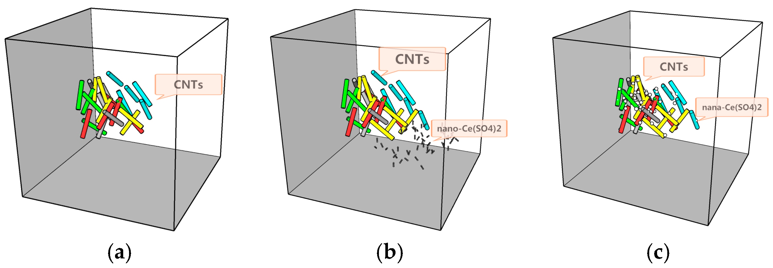
Ce2+ is easily adsorbed onto the surface of materials [26,27]. Microbubbles in the solutions are exploded instantly under the effect of ultrasound, and then a large amount of energy is produced in the following. The large amount of energy can impact the CNT aggregates seriously and damage the Van der Waals force among them. Meanwhile, the temperature of some solutions is increased rapidly due to the large amount of thermal energy released. On the basis of the two reasons discussed above, the connection among the aggregates of CNTs is interrupted. Nano-Ce(SO4)2 is adsorbed onto the surface of CNTs, and then an electrostatic layer is developed on the surface of CNTs, leading to the destruction of the Van der Waals force among the CNTs. Steric hindrance of the reactions is increased by the adsorption of nano-Ce(SO4)2 onto the surface of CNTs, and then the access between CNTs is disabled. Thus, the stability of CNT dispersion is achieved upon the complete dispersion of the CNTs (Figure 6). Figure 6 describes the process of adsorption from nano-Ce(SO4)2 to CNTs through Pro/Engineer (Pro-E) software. Figure 6a presents the large amount of aggregative CNT. Figure 6b shows that nano-Ce(SO4)2 is added into CNT dispersion. Figure 6c indicates that nano-Ce(SO4)2 is adsorbed onto the surface of CNTs under the effect of ultrasound.
3.2. Compressive and Breaking Strength
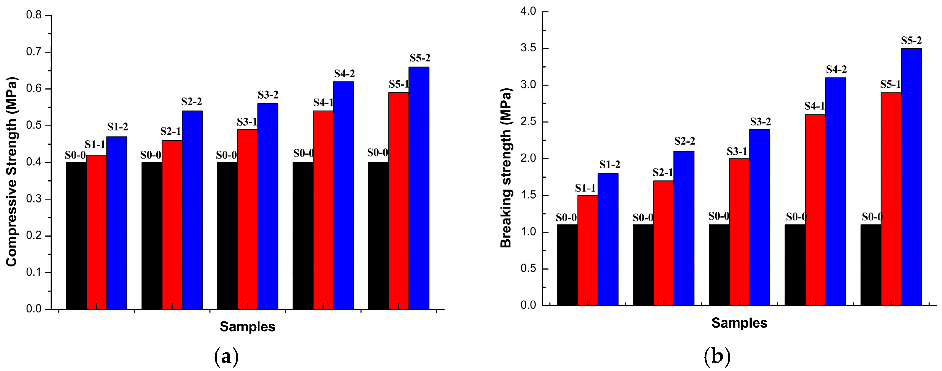
The compressive and breaking strengths of foamed concrete described in Table 1 are presented in Figure 7. Figure 7a shows the following results:
- The compressive strengths of FC1-2 and FC1-1 are 17.5% and 5% greater than that of FC0-0, respectively; those of FC2-2 and FC2-1 are 35% and 15% greater than that of FC0-0, respectively; those of FC3-2 and FC3-1 are 40% and 22.5% greater than that of FC0-0, respectively; those of FC4-2 and FC4-1 are 55% and 35% greater than that of FC0-0, respectively; and those of FC5-2 and FC5-1 are 65% and 47.5% greater than that of FC0-0, respectively. Better CNT dispersion corresponds to higher compressive strength of foamed concrete.
- The compressive strength of foamed concrete is increased by 11.9% from FC1-2 to FC1-1, by 17.3% from FC2-2 to FC2-1, by 14.2% from FC3-2 to FC3-1, by 14.8% from FC4-2 to FC4-1, and by 11.9% from FC5-2 to FC5-1. The results indicate that the increases in compressive strength of foamed concrete are almost the same due to the same contents of 0.3% nano-Ce(SO4)2 added in the CNT dispersion solution although the contents of CNTs are different. The result is the same as described in Figure 2, above. Thus, CNT dispersion is an important factor that determines the compressive strength of foamed concrete.
Figure 7b shows the following results:
- The breaking strengths of FC1-2 and FC1-1 are 63.6% and 36.4% greater than that of FC0-0, respectively; those of FC2-2 and FC2-1 are 90.9% and 54.5% greater than that of FC0-0, respectively; those of FC3-2 and FC3-1 are 118.2% and 81.8% greater than that of FC0-0, respectively; those of FC4-2 and FC4-1 are 181.8% and 136.4% greater than that of FC0-0, respectively and those of FC5-2 and FC5-1 are 218.2% and 163.6% greater than that of FC0-0, respectively. Better CNT dispersion corresponds to higher breaking strength of foamed concrete.
- The breaking strength of foamed concrete is increased by 20% from FC1-2 to FC1-1, by 23.5% from FC2-2 to FC2-1, by 20% FC3-2 to FC3-1, by 19.2% from FC4-2 to FC4-1, and by 20.7% from FC5-2 to FC5-1. The results indicate that the increases in breaking strength of foamed concrete are almost the same due to the same contents of 0.3% nano-Ce(SO4)2 added in the CNT dispersion solution although the contents of CNTs are different. The result is the same as described in Figure 2, above. Thus, CNT dispersion is an important factor that determines the breaking strength of foamed concrete.
- Meanwhile, the crack propagation of foamed concrete is inhibited by CNTs. A large area of the crack propagation of foamed concrete can be inhibited due to the homogeneous CNT dispersion, and the breaking strength of foamed concrete is enhanced.
Figure 7a,b show that (i) CNT dispersion has a greater contribution to increasing the compressive strength than the breaking strength and (ii) the effect of the same content of weight of 0.3% nano-Ce(SO4)2 on the compressive and breaking strengths of foamed concrete is almost the same, i.e., 11.9–17.3% increase rate of compressive strength (5.4% maximum difference) and 19.2–23.5% increase rate of breaking strength (4.3% maximum difference).
3.3. Microstructure
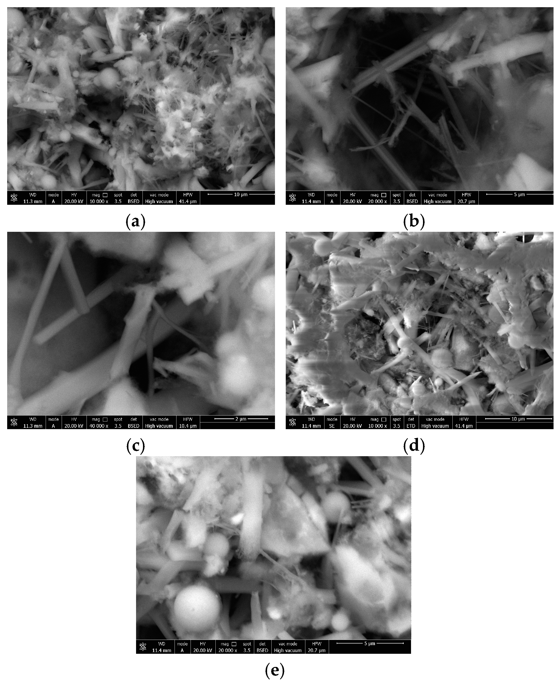
The microstructure of the CNT/foamed concretes can be observed in Figure 8. The effect of CNTs on the C–S–H growth and interface bonding force is discussed. CNT fibers are distributed uniformly between the foamed concrete and combined in the foamed concrete particles closely, as illustrated in Figure 8a. Figure 8b,c shows the relationship between CNTs and C–S–H. CNTs and C–S–H are interlaced with each other, forming a compact grid. On the basis of nucleation mechanism, CNTs play a nuclear role in the crystallization of C–S–H, signifying that the effective dispersion of CNTs promotes the grain growth of C–S–H. Thus, CNT dispersion is the most important factor influencing the increase in compressive strength.
In addition to the mean CNTs values, the other values regarding the interface bonding force between foamed concrete particles and C-S-H are reported. As shown in Figure 8d,e, CNTs are distributed not only between foamed concrete particles and particles but also between foamed concrete particles and C–S–H. Figure 7b illustrates that foamed concrete with well-dispersed CNTs exhibits an improved behavior, suggesting that CNTs can improve the interface bonding force.
3.4. CNT Dispersion Model and Mechanical Properties of the Simulation
Despite the importance of CNT dispersion in the performance of foamed concrete, CNT dispersion models are established scarcely possibly because the mass of pores in the foamed concrete is difficult to model. Foamed concrete is a typical porous material with characteristics similar to those of a pore structure unit and with a certain distribution of pores at a macroscopic state. This study focuses on the influence of aggregated and dispersed CNTs on the mechanical properties of foamed concrete. A type of isotropic foamed concrete is established, and the pores in the foamed concrete are not considered when modeling. In the process modeling, CNTs form the micro unit, whereas foamed concrete is the macro unit.
Pro/Engineer (Pro-E) software is an entity modeling system that uses parametric design based on physical characteristics. The CNT dispersion of the foamed concrete model is established, and the mechanical performance is simulated, using the Pro-E software. The effects of the CNT dispersion of foamed concrete on the compressive and breaking strengths are studied.
3.4.1. Modeling
The boundary representation model, the decomposition model, and the construct solid geometry model are widely used at present. Precision is difficult to achieve with the boundary representation model due to the large number of curves and surfaces in the CNT/foamed concrete material [31]. If the decomposition model is used, two scales of macro (foamed concrete) and micro(CNTs) are present in the foamed concrete [32]. In addition, not only the size and scale of the macro structure, but also the microstructure of the model, should be established, and a quantity of voxels should be used [33]. Therefore, the constructive solid geometry model is adopted in this study, which is combined through the Boolean operation method.
The model of foamed concrete features a complicated structure unit and a high degree of freedom. Thus, the calculating quantity of grid computation is large if the grid is generated directly. In particular, long computation time is expended if the finite element simulation method is used for the simulation directly, and this can lead to computer crash due to insufficient computing ability of the computer. To reduce the complexity of the grid generation and improve the grid quality, a previous study suggested simplifying the models before simulation [34]. Some researchers have introduced a method of model simplification based on rules and realized the development on the plug-in of model that is simplified based on the Pro-E software (Parametric Technology Corporation, Boston, MA, USA) [35]. Figure 8 shows that that the dispersed CNTs are distributed evenly in the foamed concrete. If the CNT unit is defined as the micro unit while the foamed concrete unit is defined as the macro unit, then the CNT unit is defined as spherical by the finite element method.
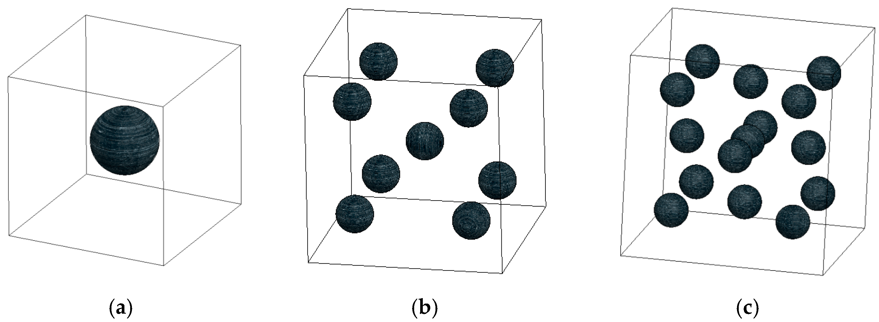
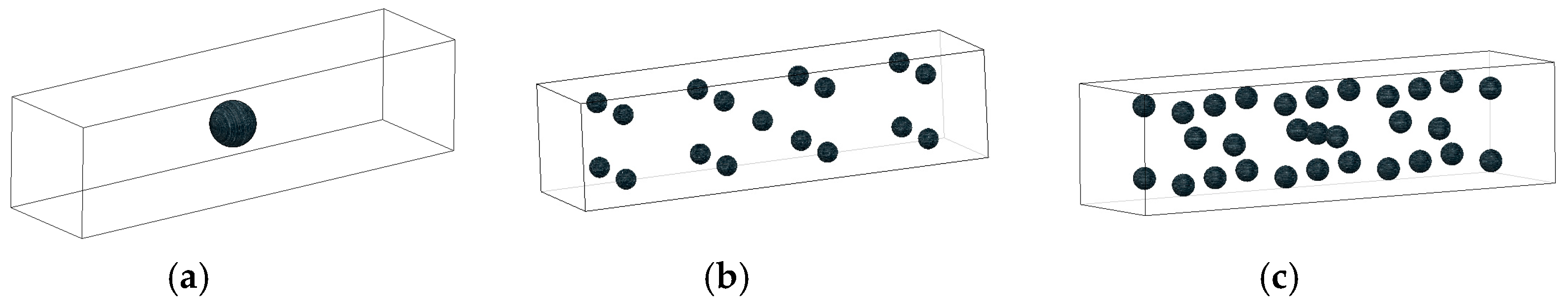
Based on the mechanical property test, two models with dimensions of 100 mm × 100 mm × 100 mm (Figure 9) and 400 mm × 100 mm × 100 mm (Figure 10) are established to simulate the compressive and breaking strength tests, respectively. Modeling parameters are shown in Table 4. A microstructure scale that describes the CNTs inside the foamed concrete and a macrostructure scale that describes the external size of foamed concrete are obtained in the two models.
3.4.2. Simulation
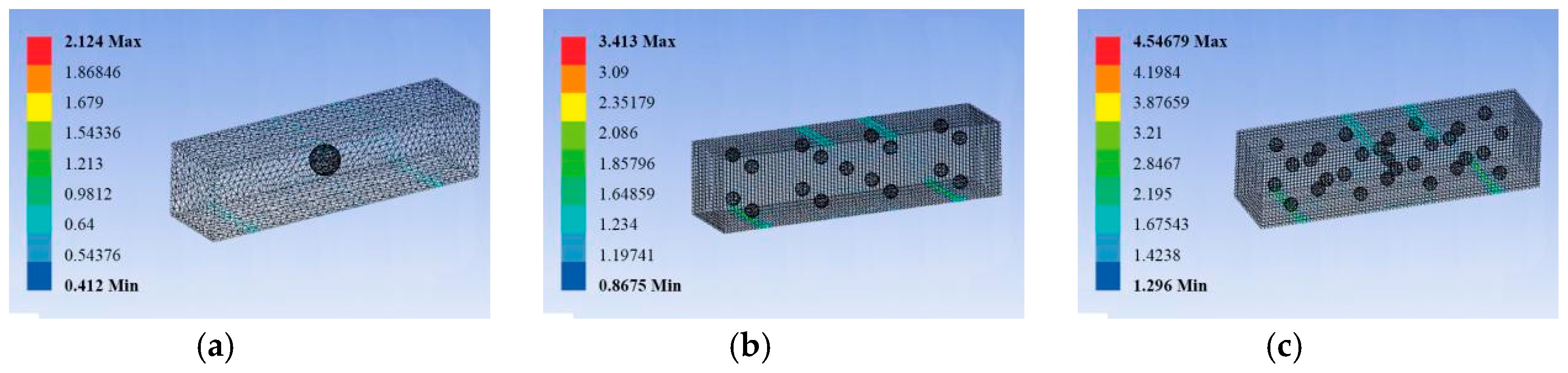
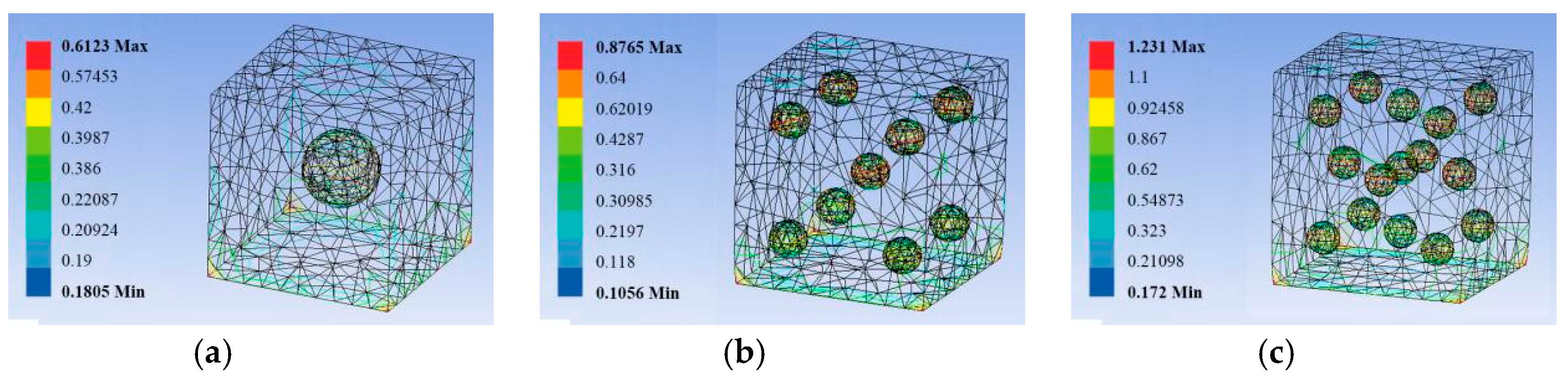
In this section, we report the simulation results regarding the influence of CNT dispersion on compressive and breaking strengths. To improve the accuracy of the models, we define the CNT dispersion as three conditions, namely, aggregated completely (Figure 11a and Figure 12a), dispersion ratio of 50% (Figure 11b and Figure 12b), and dispersion ratio of 100% (Figure 11c and Figure 12c).
As expected, Figure 11a shows that the CNTs are aggregated completely and the compressive strength is 0.6123 MPa. Figure 11b illustrates that the dispersion ratio of CNTs is 50% and the compressive strength is 0.8765 MPa. Figure 11c displays that the dispersion ratio of CNTs is 100% and the compressive strength is 1.231 MPa. These results indicate that better CNT dispersion corresponds to increased compressive strength. This noticeable result is fully in line with the experimental findings (Figure 7a) and is useful to explain the previous quantification methods on a theoretical basis.
Figure 12 compares the same target breaking strength obtained from the three situations of CNT dispersion. Figure 12a shows that the CNTs are aggregated completely and the breaking strength is 2.124 MPa. Figure 12b shows that the dispersion ratio of CNTs is 50% and the breaking strength is 3.413 MPa. Figure 12c shows that dispersion ratio of CNTs is 100% and the breaking strength is 4.54678 MPa. Similarly, better CNT dispersion corresponds to remarkably increased breaking strength, which agrees with the experimental results (Figure 7b).
The experimental findings presented in the previous sections are analyzed to determine simulation results for prediction purposes. The simulation results are based on the idealized assumptions of foamed concrete. Therefore, the simulation results are valid only for foamed concrete specimens with similar characteristics.
4. Conclusions
The effect of CNT dispersion on the microstructure and mechanical properties of foamed concrete is investigated. The effect of CNT dispersion on compressive and breaking strengths is simulated. Results show that the addition of nano-Ce(SO4)2 improves CNT dispersion by increasing the degree of distribution and dispersion of CNT particles in solution. In particular, the structure of CNTs is not destroyed due to the addition of nano-Ce(SO4)2 to the dispersion. The enormous uniformity and stability observed are ascribed to the properties, including activity, adsorption, and structure, of nano-Ce(SO4)2, which has modified the surface of CNTs.
CNT dispersion increases the compressive and breaking strengths of foamed concrete. CNTs play a nuclear role in the crystallization of C–S–H. The dispersion of CNTs effectively promotes the grain growth of C–S–H, forming a compact grid. Finally, the effect of CNT dispersion on the compressive and breaking strengths of foamed concrete is predicted through simulation to provide a theoretical basis for the experimental findings.
Author Contributions
J.Z. and X.L. conceived and designed the experiments; J.Z. performed the experiments; J.Z. and X.L. analyzed the data; J.Z. wrote the paper.
Funding
This research was funded by Inner Mongolia autonomous region education department grant number [NJZC13344 and NJZY17487].
Conflicts of Interest
The authors declare no conflict of interest.
References
- Falliano, D.; de Domenico, D.; Ricciardi, G.; Gugliandolo, E. Experimental investigation on the compressive strength of foamed concrete: Effect of curing conditions, cement type, foaming agent and dry density. Constr. Build. Mater. 2018, 165, 735–749. [Google Scholar] [CrossRef]
- She, W.; Du, Y.; Miao, C.; Liu, J.; Zhao, G.; Jiang, J.; Zhang, Y. Application of organic- and nanoparticle-modified foams in foamed concrete: Reinforcement and stabilization mechanisms. Cem. Concr. Res. 2018, 106, 12–22. [Google Scholar] [CrossRef]
- Gunawana, P.; Setionob. Foamed lightweight concrete tech using galvalum Az 150 fiber. Procedia Eng. 2014, 95, 433–441. [Google Scholar] [CrossRef]
- Vesova, L.M. Disperse Reinforcing Role in Producing Non-autoclaved Cellular Foam Concrete. Procedia Eng. 2016, 150, 1587–1590. [Google Scholar] [CrossRef]
- Mahzabin, M.S.; Hock, L.J.; Hossain, M.S.; Kang, L.S. The influence of addition of treated kenaf fibre in the production and properties of fibre reinforced foamed composite. Constr. Build. Mater. 2018, 178, 518–528. [Google Scholar] [CrossRef]
- Mastali, M.; Kinnunen, P.; Isomoisio, H.; Karhu, M.; Illikainen, M. Mechanical and acoustic properties of fiber-reinforced alkali-activated slag foam concretes containing lightweight structural aggregates. Constr. Build. Mater. 2018, 187, 371–381. [Google Scholar] [CrossRef]
- Eftekhari, M.; Ardakani, S.H.; Mohammadi, S. An XFEM multiscale approach for fracture analysis of carbon nanotube reinforced concrete. Theor. Appl. Fract. Mech. 2014, 72, 64–75. [Google Scholar] [CrossRef]
- Zhang, S.; Luo, J.; Li, Q.; Wei, X.; Sun, S. Physico-mechnical and damping performances of carbon nanotubes modified foamed concrete. Concrete 2015, 306, 78–81. [Google Scholar]
- Luo, J.; Hou, D.; Li, Q.; Wu, C.; Zhang, C. Comprehensive performances of carbon nanotube reinforced foam concrete with tetraethyl orthosilicate impregnation. Constr. Build. Mater. 2017, 131, 512–516. [Google Scholar] [CrossRef]
- Vaganov, V.; Popov, M.; Korjakins, A.; Šahmenko, G. Effect of CNT on Microstructure and Minearological Composition of Lightweight Concrete with Granulated Foam Glass. Procedia Eng. 2017, 172, 1204–1211. [Google Scholar] [CrossRef]
- Ferreira, F.V.; Francisco, W.; Menezes, B.R.C.; Brito, F.S.; Coutinho, A.S.; Cividanes, L.S.; Coutinho, A.R.; Thim, G.P. Correlation of surface treatment, dispersion and mechanical properties of HDPE/CNT nanocomposites. Appl. Surf. Sci. 2016, 389, 921–929. [Google Scholar] [CrossRef]
- Kim, G.M.; Yang, B.J.; Cho, K.J.; Kim, E.M.; Lee, H.K. Influences of CNT dispersion and pore characteristics on the electrical performance of cementitious composites. Compos. Struct. 2017, 164, 32–42. [Google Scholar] [CrossRef]
- Arboleda-Clemente, L.; Ares-Pernas, A.; García, X.; Dopico, S.; Abad, M.J. Influence of polyamide ratio on the CNT dispersion in polyamide 66/6 blends by dilution of PA66 or PA6-MWCNT masterbatches. Synth. Met. 2016, 221, 134–141. [Google Scholar] [CrossRef]
- Liu, L.; Bao, R.; Yi, J.; Li, C.; Tao, J.; Liu, Y.; Tan, S.; You, X. Well-dispersion of CNTs and enhanced mechanical properties in CNTs/Cu-Ti composites fabricated by Molecular Level Mixing. J. Alloy. Compd. 2017, 726, 81–87. [Google Scholar] [CrossRef]
- Eftekhari, M.; Mohammadi, S.; Khanmohammadi, M. A hierarchical nano to macro multiscale analysis of monotonic behavior of concrete columns made of CNT-reinforced cement composite. Constr. Build. Mater. 2018, 175, 134–143. [Google Scholar] [CrossRef]
- Eftekhari, M.; Karrech, A.; Elchalakani, M.; Basarir, H. Multi-scale Modeling Approach to Predict the Nonlinear Behavior of CNT reinforced Concrete Columns Subjected to Service Loading. Structures 2018, 14, 301–312. [Google Scholar] [CrossRef]
- Zou, B.; Chen, S.J.; Korayem, A.H.; Collins, F.; Wang, C.M.; Duan, W.H. Effect of ultrasonication energy on engineering properties of carbon nanotube reinforced cement pastes. Carbon 2015, 85, 212–220. [Google Scholar] [CrossRef]
- Mendoza, O.; Sierra, G.; Tobón, J.I. Influence of super plasticizer and Ca(OH)2 on the stability of functionalized multi-walled carbon nanotubes dispersions for cement composites applications. Constr. Build. Mater. 2013, 47, 771–778. [Google Scholar] [CrossRef]
- Kang, L.; Du, H.L.; Zhang, H.; Ma, W.L. Systematic research on the application of steel slag resources under the background of big data. Complexity 2018. [CrossRef]
- Fu, H.; Li, Z.; Liu, Z.; Wang, Z. Research on Big Data Digging of Hot Topics about Recycled Water Use on Micro-Blog Based on Particle Swarm Optimization. Sustainability 2018, 10, 2488. [Google Scholar] [CrossRef]
- Yang, A.M.; Yang, X.L.; Chang, J.C.; Bai, B.; Kong, F.B.; Ran, Q.B. Research on a fusion scheme of cellular network and wireless sensor networks for cyber physical social systems. IEEE Access 2018, 6, 18786–18794. [Google Scholar] [CrossRef]
- Zhang, Q.; Jin, B.; Wang, X.; Lei, S.; Shi, Z.; Zhao, J.; Liu, Q.; Peng, R. The mono (catecholamine) derivatives as iron chelators: Synthesis, solution thermodynamic stability and antioxidant properties research. R. Soc. Open Sci. 2018, 5, 171492. [Google Scholar] [CrossRef] [PubMed]
- Liang, X.; Li, W. Dispersion Properties of Aligned Multi-Walled Carbon Nanotubes. J. Dispers. Sci. Technol. 2016, 37, 1360–1367. [Google Scholar] [CrossRef]
- Sindu, B.S.; Sasmal, S. Properties of carbon nanotube reinforced cement composite synthesized using different types of surfactants. Constr. Build. Mater. 2017, 155, 389–399. [Google Scholar] [CrossRef]
- Chaichi, A.; Sadrnezhaad, S.K.; Malekjafarian, M. Synthesis and characterization of supportless Ni-Pd-CNT nanocatalyst for hydrogen production via steam reforming of methane. Int. J. Hydrogen Energy 2018, 43, 1319–1336. [Google Scholar] [CrossRef]
- Chen, J.; Luo, W.; Guo, A. Preparation of novel carboxylate-rich palygorskite as an adsorbent for Ce3+ for aqueous solution. J. Colloid Interface Sci. 2018, 512, 657–664. [Google Scholar] [CrossRef] [PubMed]
- Ogata, T.; Narita, H.; Tanaka, M. Adsorption behavior of rare earth elements on silica gelmodified with diglycol amic acid. Hydrometallrugy 2015, 152, 178–182. [Google Scholar] [CrossRef]
- Pichler, B.; Hellmich, C.; Eberhardsteiner, J.; Wasserbauer, J.; Termkhajornkit, P.; Barbarulo, R.; Chanvillard, G. Effect of gel–space ratio and microstructure on strength of hydrating cementitious materials: An engineering micromechanics approach. Cem. Concr. Res. 2013, 45, 55–68. [Google Scholar] [CrossRef]
- Eftekhari, M.; Mohammadi, S. Molecular dynamics simulation of the nonlinear behavior of the CNT-reinforced calcium silicate hydrate (C–S–H) composite. Compos. Part A Appl. Sci. Manuf. 2016, 82, 78–87. [Google Scholar] [CrossRef]
- Hlobil, M.; Šmilauer, V.; Chanvillard, G. Micromechanical multiscale fracture model for compressive strength of blended cement pastes. Cem. Concr. Res. 2016, 83, 188–202. [Google Scholar] [CrossRef]
- Liu, Z.; Cheng, K.; Li, H.; Cao, G.; Wu, D.; Shi, Y. Exploring the potential relationship between indoor air quality and the concentration of airborne culturable fungi: A combined experimental and neural network modeling study. Environ. Sci. Pollut. Res. 2018, 25, 3510–3517. [Google Scholar] [CrossRef] [PubMed]
- Jiang, S.; Lian, M.; Lu, C.; Gu, Q.; Ruan, S.; Xie, X. Ensemble Prediction Algorithm of Anomaly Monitoring Based on Big Data Analysis Platform of Open-Pit Mine Slope. Complexity 2018, 2018, 1048756. [Google Scholar] [CrossRef]
- Liu, T.; Liu, H.; Chen, Z.; Lesgold, A.M. Fast Blind Instrument Function Estimation Method for Industrial Infrared Spectrometers. IEEE Trans. Ind. Inform. 2018. [Google Scholar] [CrossRef]
- Li, M. Review on Engineering Analysis Reliable CAD Model Simplification. J. Comput.-Aided Des. Comput. Graph. 2015, 27, 1363–1375. [Google Scholar]
- Papadopoulos, V.; Impraimakis, M. Multiscale modeling of carbon nanotube reinforced concrete. Compos. Struct. 2017, 182, 251–260. [Google Scholar] [CrossRef]
Figure 1.
TEM of CNTs. (a) aggregate of CNTs (b) multi-walled CNT.

Figure 2.
Absorbance of CNT dispersion.

Figure 3.
Impact of time on the absorbance of CNT dispersion. (a) 0.3% nano-Ce(SO4)2, (b) 0.6% nano-Ce(SO4)2.
Figure 3.
Impact of time on the absorbance of CNT dispersion. (a) 0.3% nano-Ce(SO4)2, (b) 0.6% nano-Ce(SO4)2.
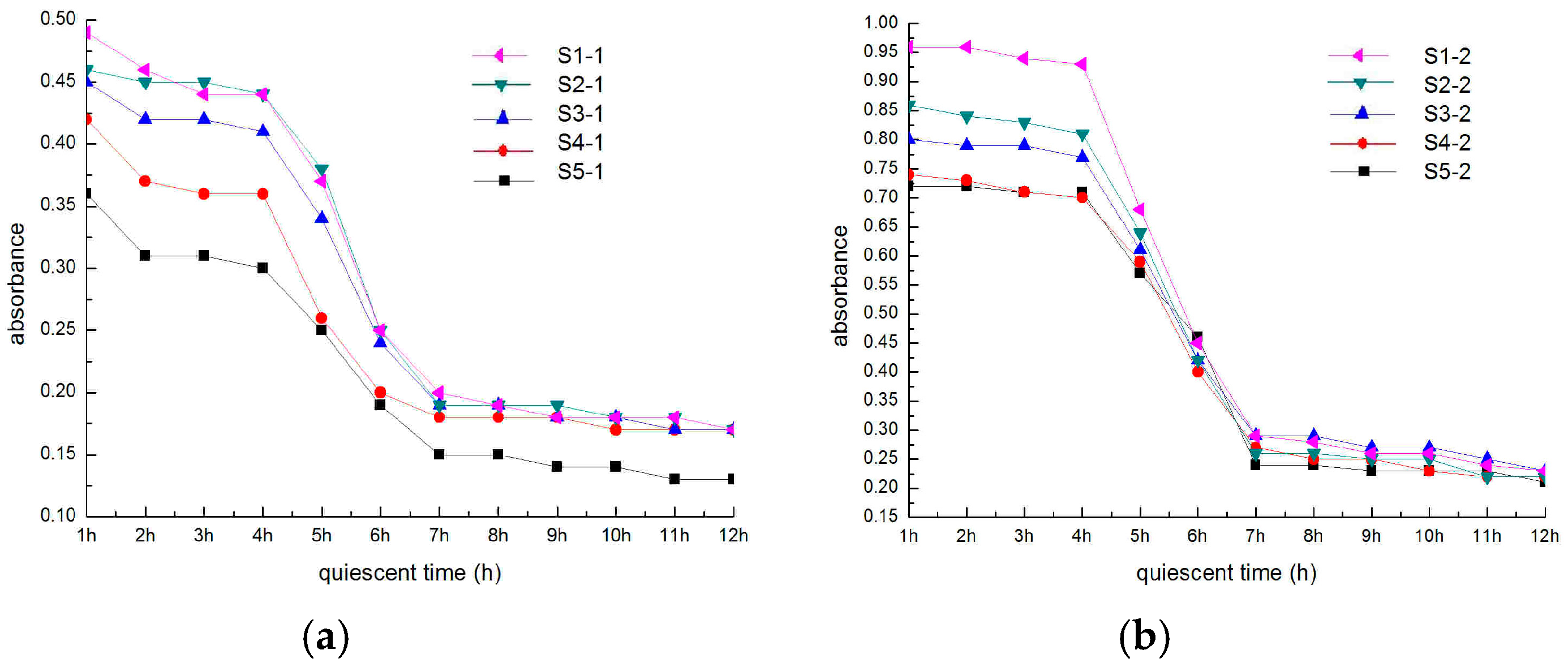
Figure 4.
CNT dispersion. (a) without Ce(SO4)2, (b) 0.3 wt.% Ce(SO4)2, (c) 0.6 wt.% Ce(SO4)2, (d) 0.6 wt.% Ce(SO4)2 (single).
Figure 4.
CNT dispersion. (a) without Ce(SO4)2, (b) 0.3 wt.% Ce(SO4)2, (c) 0.6 wt.% Ce(SO4)2, (d) 0.6 wt.% Ce(SO4)2 (single).

Figure 5.
Surface of CNTs. (a) without nano-Ce(SO4)2, (b) with nano-Ce(SO4)2, (c) with nano-Ce(SO4)2.
Figure 5.
Surface of CNTs. (a) without nano-Ce(SO4)2, (b) with nano-Ce(SO4)2, (c) with nano-Ce(SO4)2.
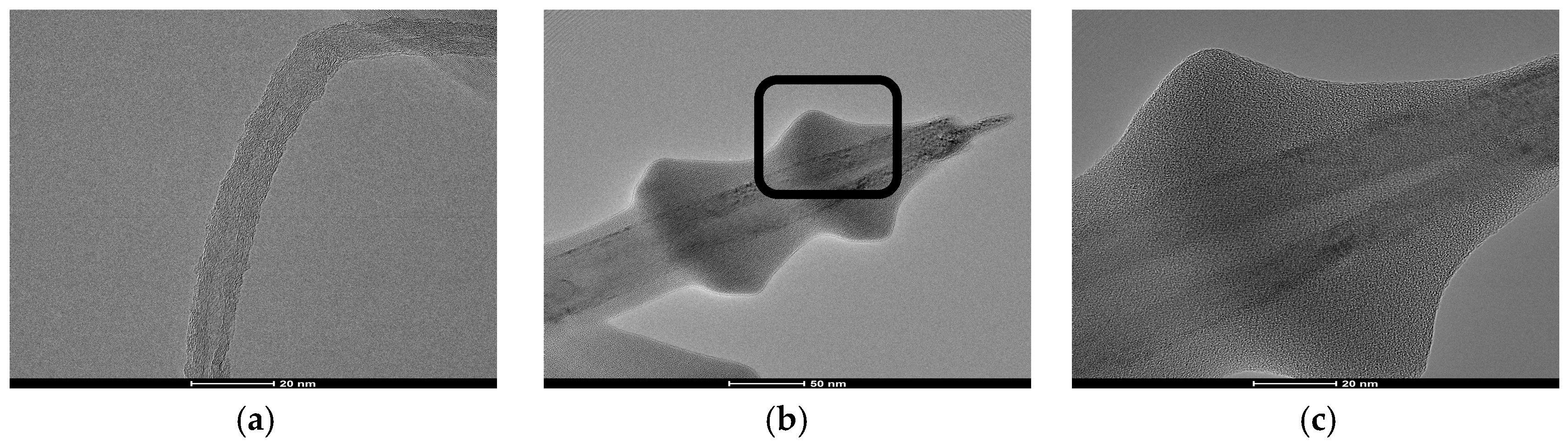
Figure 6.
Adsorption of nano-Ce(SO4)2 on the surface of CNTs. (a) without nano-Ce(SO4)2, (b) with nano-Ce(SO4)2, (c) nano-Ce(SO4)2 is adsorbed.
Figure 6.
Adsorption of nano-Ce(SO4)2 on the surface of CNTs. (a) without nano-Ce(SO4)2, (b) with nano-Ce(SO4)2, (c) nano-Ce(SO4)2 is adsorbed.

Figure 7.
Mechanical property (28 days). (a) Compressive strength, (b) breaking strength.

Figure 8.
Microstructure of CNTs/foamed concretes with different magnification times. (a) 10 µm, (b) 5 µm, (c) 2 µm, (d) 10 µm, (e) 5 µm.
Figure 8.
Microstructure of CNTs/foamed concretes with different magnification times. (a) 10 µm, (b) 5 µm, (c) 2 µm, (d) 10 µm, (e) 5 µm.

Figure 9.
Model of compressive strength (Strain). (a) Aggregated completely, (b) dispersion ratio of 50%, (c) dispersion ratio of 100%.
Figure 9.
Model of compressive strength (Strain). (a) Aggregated completely, (b) dispersion ratio of 50%, (c) dispersion ratio of 100%.

Figure 10.
Model of breaking strength (Strain). (a) Aggregated completely, (b) dispersion ratio of 50%, (c) dispersion ratio of 100%.
Figure 10.
Model of breaking strength (Strain). (a) Aggregated completely, (b) dispersion ratio of 50%, (c) dispersion ratio of 100%.

Figure 11.
Simulation model of compressive strength (Strain). (a) Aggregated completely, (b) dispersion ratio of 50%, (c) dispersion ratio of 100%.
Figure 11.
Simulation model of compressive strength (Strain). (a) Aggregated completely, (b) dispersion ratio of 50%, (c) dispersion ratio of 100%.

Figure 12.
Simulation model of breaking strength (Strain). (a) Aggregated completely, (b) dispersion ratio of 50%, (c) dispersion ratio of 100%.
Figure 12.
Simulation model of breaking strength (Strain). (a) Aggregated completely, (b) dispersion ratio of 50%, (c) dispersion ratio of 100%.

Table 1.
Physical and mechanical properties of multi-walled carbon nanotubes.
| Type | Inner Diameter (nm) | External Diameter (nm) | Length (μm) | Tensile Strength (GPa) | Modulus of Elasticity (TPa) |
|---|---|---|---|---|---|
| Multi-walled carbon nanotubes | 8–12 | 25–30 | 5–15 | 10–60 | 1 |
Table 2.
CNT dispersion and the corresponding foamed concretes.
| CNT (mass%) | Nano-Ce(SO4)2 (mass%) | CNT Dispersion | Foamed Concrete |
|---|---|---|---|
| 0.0% | 0.0% | S0-0 | FC0-0 |
| 0.1% | 0.3% | S1-1 | FC1-1 |
| 0.1% | 0.6% | S1-2 | FC1-2 |
| 0.2% | 0.3% | S2-1 | FC2-1 |
| 0.2% | 0.6% | S2-2 | FC2-2 |
| 0.3% | 0.3% | S3-1 | FC3-1 |
| 0.3% | 0.6% | S3-2 | FC3-2 |
| 0.4% | 0.3% | S4-1 | FC4-1 |
| 0.4% | 0.6% | S4-2 | FC4-2 |
| 0.5% | 0.3% | S5-1 | FC5-1 |
| 0.5% | 0.6% | S5-2 | FC5-2 |
Table 3.
CNT dispersion solution.
| Solution | A | B | C |
|---|---|---|---|
| Water | 50 mL | 50 mL | 50 mL |
| Nano-Ce(SO4)2 | 0% | 0.3 wt% | 0.6 wt% |
Table 4.
Modeling parameters.
| Material | Mechanical Properties | Size | Force | Modulus of Elasticity | Poisson Ratio |
|---|---|---|---|---|---|
| Concrete | Compressive strength | 100 mm × 100 mm × 100 mm | 2 kN | 30,000 MPa | 0.2 |
| Breaking strength | 400 mm × 100 mm × 100 mm | 0.2 kN | 30,000 MPa | 0.2 |
© 2018 by the authors. Licensee MDPI, Basel, Switzerland. This article is an open access article distributed under the terms and conditions of the Creative Commons Attribution (CC BY) license (http://creativecommons.org/licenses/by/4.0/).
Share and Cite
MDPI and ACS Style
Zhang, J.; Liu, X. Dispersion Performance of Carbon Nanotubes on Ultra-Light Foamed Concrete. Processes 2018, 6, 194. https://doi.org/10.3390/pr6100194
AMA Style
Zhang J, Liu X. Dispersion Performance of Carbon Nanotubes on Ultra-Light Foamed Concrete. Processes. 2018; 6(10):194. https://doi.org/10.3390/pr6100194
Chicago/Turabian StyleZhang, Jing, and Xiangdong Liu. 2018. "Dispersion Performance of Carbon Nanotubes on Ultra-Light Foamed Concrete" Processes 6, no. 10: 194. https://doi.org/10.3390/pr6100194
Note that from the first issue of 2016, this journal uses article numbers instead of page numbers. See further details here.