
Production Calculation Model of Thermal Recovery after Hydraulic Fracturing and Packing in Tight Reservoir


1
School of Petroleum Engineering, Northeast Petroleum University, Daqing 163318, China
2
Russian Project Department of International Exploration and Development Corporation, Daqing Oilfield Limited Company, Daqing 163453, China
3
Skill Training Department, Tieren College, Daqing 163255, China
4
Heilongjiang Key Laboratory of Gas Hydrate Efficient Development, Daqing 163318, China
5
College of Offshore Oil & Gas Engineering, Northeast Petroleum University, Daqing 163318, China
6
CNOOC Research Institute Co., Ltd., Beijing 100027, China
*
Author to whom correspondence should be addressed.
Processes 2021, 9(12), 2226; https://doi.org/10.3390/pr9122226
Submission received: 4 November 2021
/
Revised: 4 December 2021
/
Accepted: 7 December 2021
/
Published: 9 December 2021
(This article belongs to the Special Issue New Challenges in Advanced Process Control in Petroleum Engineering)
Abstract
:It was deemed important to calculate the thermal recovery production model of tight oil reservoirs after fracturing and packing based on the field data of an oilfield in Bohai Sea, China. The thermal recovery production of a tight oil reservoir after fracturing is demonstrated through theoretical calculation and practical field data on the premise of five hypotheses. Fractures change the fluid flow capacity of the reservoir. Combined with the relevant theories of reservoir thermal production, the dual porosity system in the fractured zone and the single porosity system in the unfractured zone were established. The calculation models of heat loss in the fractured and unfractured zones were derived to determine the thermal recovery heating radius of the reservoir after fracturing and packing. Combined with the pseudo-steady state productivity formula of the composite reservoir, a production calculation model of thermal recovery after fracturing and packing in the tight oil reservoir was established. The results showed that the heating radius of the reservoir after fracturing and packing is smaller than that of the unfractured reservoir, and the additional heat absorption of the fracture system generated by fracturing and packing reduces the thermal recovery effect. The thermal recovery productivity of heavy oil reservoirs is mainly affected by the heating radius. With the increase of fracture density, the heating radius decreases and production decreases. The increase of fracture porosity also leads to the decrease of the heating radius and the production. The calculation result of this model is improved after tight oil reservoir fracturing during the production period, which indicates that the model has a better prediction effect of the production of the tight reservoir after fracturing and packing.
1. Introduction
The recoverable reserves of global heavy oil are about 400 billion tons, 2.7 times that of conventional crude oil. The high content of resins and asphalt in heavy oil leads to high viscosity and poor fluidity in reservoir conditions. Because the viscosity of heavy oil is sensitive to temperature and decreases rapidly with the increase of temperature, thermal recovery technologies such as steam flooding integrated with fracturing or other measures are adopted for the development of heavy oil. Compared with conventional heavy oil reservoirs, the characteristics of conventional heavy oil reservoirs and the influence of fractures after fracturing and packing should be considered during thermal recovery. In general, fracturing technology improves reservoir properties and permeability, making it easier for oil and gas to flow into the wellbore. However, the introduction of proppant and changes in filtration patterns during fracturing can have an impact on thermal recovery.
Thermal recovery production of the heavy oil reservoir after fracturing and packing is closely related to reservoir rock and fluid, fracture distribution, and proppant properties. Previous research has conducted a lot of work on productivity prediction of the heavy oil reservoir with fractures and the fractured reservoir [1,2,3]. However, there is little research on the thermal recovery productivity model of heavy oil after fracturing, and the influence of hydraulic fracture propagation on the subsequent thermal production capacity is not clear. The existing problems are summarized as follows: First, the current calculation model of thermal recovery is limited to reservoir types and has only studied reservoirs with fracture or common single porosity reservoirs. There are few studies on the thermal recovery model of the reservoir after hydraulic fracturing which lead to a complex fluid flow environment. Second, as an effective stimulation and sand control measure in tight reservoirs, there has been no relevant study on the influence of proppant in hydraulic fractures on the subsequent thermal production capacity.
Therefore, in this paper, from the perspective of the hydraulic fracture reconstructing reservoir permeability, combined with reservoir thermal recovery, the dual porosity system of the fractured zone and the single porosity system of the unfractured zone are both established. A heat loss calculation model is derived and the heating radius of thermal recovery after reservoir fracturing and packing are determined. Incorporated with the pseudo-steady state deliverability equation of the compound reservoir, a production calculation model of the thermal recovery of the tight oil reservoir after fracturing and packing is established. Combined with actual production data of the China Bohai oil field, through theoretical calculation and practical experience, the thermal recovery production of the tight oil reservoir after fracturing was demonstrated. These results are innovative and can provide a constructive theory basis for the efficient development of other tight oil reservoirs.
2. Model Establishment
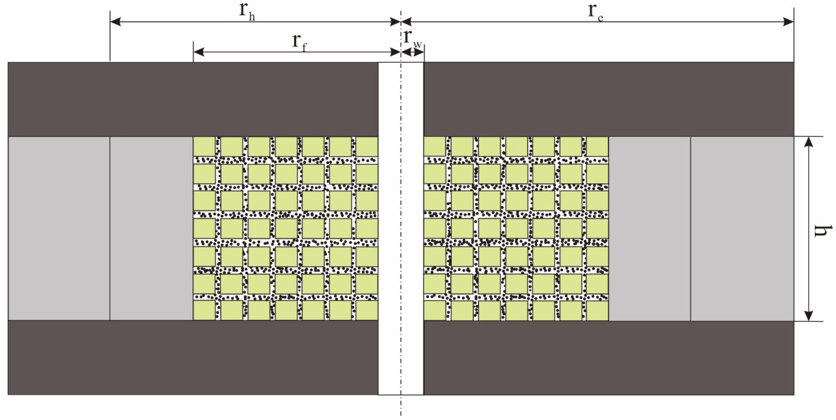
To study the thermal sweep area of thermal recovery after fracturing, the thermal sweep area is divided into the fractured zone and unfractured zone. The fractured zone is regarded as a hydraulic fractured reservoir composed of fracture-pore dual porosity media, as shown in Figure 1.
- (1)
- The temperature in the heated zone is the steam temperature.
- (2)
- During steam injection, steam injection speed and pressure remain constant.
- (3)
- Since the effect of heat conduction is much greater than that of convection, the model only considers heat conduction and does not consider the heat exchange generated by convection.
- (4)
- Some of the heat brought in by steam injection is applied to heat the matrix and fracture system, while the rest is lost in the top and bottom layers.
Before predicting oil production from the matrix, the heating radius and reservoir temperature need to be calculated:
2.1. Heating Radius
2.1.1. Fractured Zone
The fractured zone is heated by steam injection, and the heat loss during the heating process includes the heat absorption of overburden rock, underlying rock, the fracture system, and the matrix system [7].
The heat loss rate of overburden and underlying rocks [8]:
where α is the heat dissipation of overburden and underlying rocks, ∆T is the temperature difference between the original formation temperature and the steam temperature, and the specific calculation formula is as follows:
Combined with the steam injection heating area, the total heat loss of overburden and underlying rocks:
where is the area of formation heated by steam injection changed with time t, is brought into the heat loss rate formula to obtain the total heat loss of overburden and underlying rocks in time t:
At time τ (τ < t), the corresponding total heat loss is:
During steam injection, the heat loss of the fracture system is affected by fracture parameters such as fracture density and fracture porosity. At the same time, there is oil and water in the fracture. Their heat capacity needs to be considered in calculating the heat loss. In addition, the proppant in the fracture will also take away some heat. The specific calculation formula is as follows [9,10]:
To simplify the calculation, let , then the heat loss in the fracture system can be simplified as follows:
Similar to the fracture system, there are three phases of oil, gas, and water in the matrix pores, and the matrix itself also participates in heat transfer. The matrix heat dissipation coefficient D is introduced to describe the heat loss in the matrix. The calculation formula is as follows:
where and are the matrix thermal conductivity and matrix heat capacity respectively, which are affected by the matrix porosity and the fluid saturation in pores. The calculation formula is as follows:
Similar to the calculation of heat loss of overburden and underlying rocks during steam injection, the heat loss in the matrix is described by using the matrix heat dissipation coefficient:
According to the energy conservation principle, the heat of steam injection into the formation is the sum of the heat losses of overburden and underlying rocks, fractures. and matrix, that is:
where is the steam heat injected into the formation. Combined with the heat loss calculation equation of each part we obtain:
The above formula is the heat conservation formula of the steam injection fracturing area after fracturing and packing. By solving the above formula, the variation of the heating area in the fracturing area with time can be obtained.
Convolved by the function:
Let , then,
Substitute it into the conservation equation:
Thus,
Let , then,
The above equation is solved by inverse operation:
Thus,
That is,
Let .
Then,
The above formula is the calculation formula for the change of the heating area in the fracturing area with time during steam injection. When the area of the fracturing area is known, the time required for the steam injection to heat the complete fracturing area can be calculated.
2.1.2. Unfractured Zone
Similar to the calculation of heat transfer in the fracturing area, when heat is transferred to the unfractured area, the heat loss in the unfractured area includes the heat absorption of the overburden rocks, underlying rocks, and the matrix system. Fluid flow is not considered in the unfractured area, and only rock heat absorption is considered in the matrix system. Then the energy conservation of the unfractured area is:
The calculation formula of the heating area in the unfractured area is as follows:
Assuming that the heating area is circular and the fracture radius is the average fracture length, is used to calculate the time required for heat transfer to the fracturing zone boundary, When formula is used to calculate the heating area. In this case, the heating area is a circular ring, and the heating radial distance is .
2.2. Productivity Calculation
When calculating the productivity of the steam injection fracturing well, only the production in the heating area needs to be calculated. When the heating range is greater than the boundary of the fracturing area, there is discontinuous radial permeability in the formation. The average permeability of the fracturing well porous flow process is obtained according to the Bearden average permeability calculation formula:
According to the approximate solution formula of the pseudo-steady state of one well in the center of the circular closed boundary of the composite reservoir, the production is calculated as follows [12]:
where is oil production, is water production.
Parameter meaning and unit in formula:
—Heat loss rate of overburden and underlying, ;
—Coefficient of heat dissipation of overburden and underlying, ;
—Steam injection temperature, °C;
—Initial reservoir temperature, °C;
—Thermal conductivity of overburden and underlying rocks, ;
—Heat capacity of overburden and underlying rocks,
—Fracture density, ;
—Fracture porosity;
—Volumetric Heat Capacity of crude oil, ;
—Volumetric Heat Capacity of water, ;
—Volumetric Heat Capacity of proppant, ;
—Water level in the fracture, ;
—Reservoir thickness, ;
—Coefficient of heat dissipation of matrix, ;
—Coefficient of heat conductivity of matrix, ;
—Heat capacity of matrix, ;
—Coefficient of heat conductivity of rock, ;
—Coefficient of heat conductivity of water, ;
—Coefficient of heat conductivity of oil, ;
—Volumetric Heat Capacity of rock, ;
—Water saturation;
—Oil saturation;
—Water temperature in the fracture,
—Heat injection rate, ;
—Steam injection rate, ;
—Steam quality of the down hole;
—Latent heat of steam, ;
—Fractured zone permeability, ;
—Unfractured zone permeability, ;
—Average permeability, ;
—Borehole radius, ;
—Boundary radius, ;
—Fracture zone radius,
—Oil production, ;
—Water production, ;
—Average reservoir pressure, ;
—Bottom hole pressure, ;
, —Viscosity of crude oil in hot and cold zone, ;
, —Viscosity of water in hot and cold zone,;
, —Relative oil permeability, relative water permeability, ;
—Skin factor.
3. Results and Discussions
The calculation parameters are as follows (Table 1).
3.1. The Heating Radius versus Time
Based on the results, it was determined that the heating radius did not exceed the fracture length within 20 days. The calculation method of the heating area of the unfractured zone was used to calculate the heating radius of the thermal recovery without fracturing treatment under the same conditions. It can be seen from the Figure 2 that the heating radius of the thermal recovery after fracturing and packing is smaller than that of the unfractured pay zone. This is because the proppant in the fracture absorbs part of the heat when the hot steam is injected into the fractured and packed reservoir.
3.2. Thermal Recovery Yield
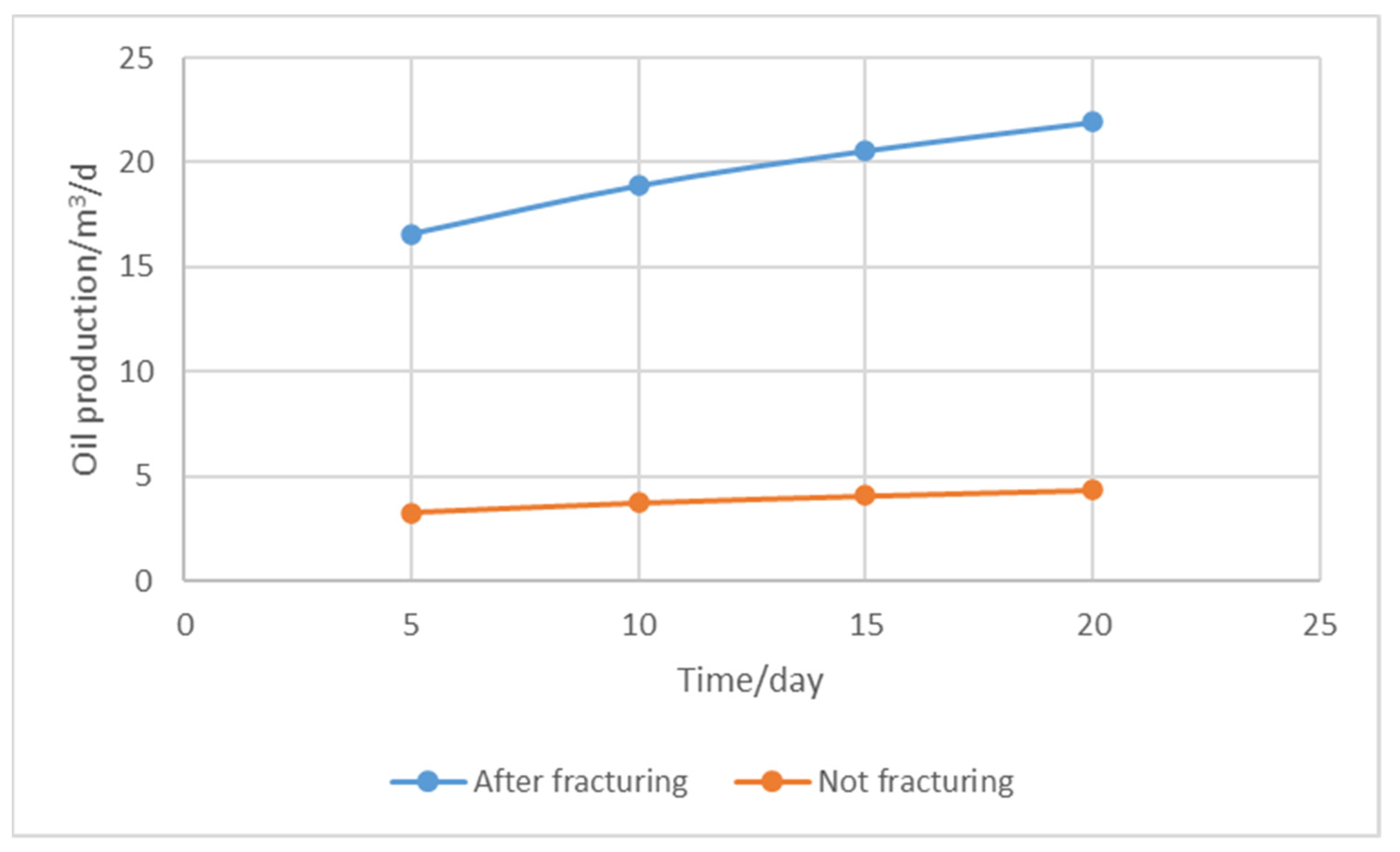
As can be seen from the Figure 3, although the heating radius of the thermal recovery reservoir after fracturing is smaller than that without fracturing, the difference is slight. However, fracturing greatly improves the reservoir permeability and productivity, so fracturing can effectively improve production.
In general, the production of conventional reservoirs increases with the increase of fracture density, but the crude oil in heavy oil reservoirs almost does not flow without heating. The main factor affecting the production is the heating radius of the heated reservoir volume. Therefore, with the increase of fracture density, the contact area between the hot steam and the matrix and proppant in the fracture increases, the heating radius decreases, and the production decreases, as shown in Figure 4.
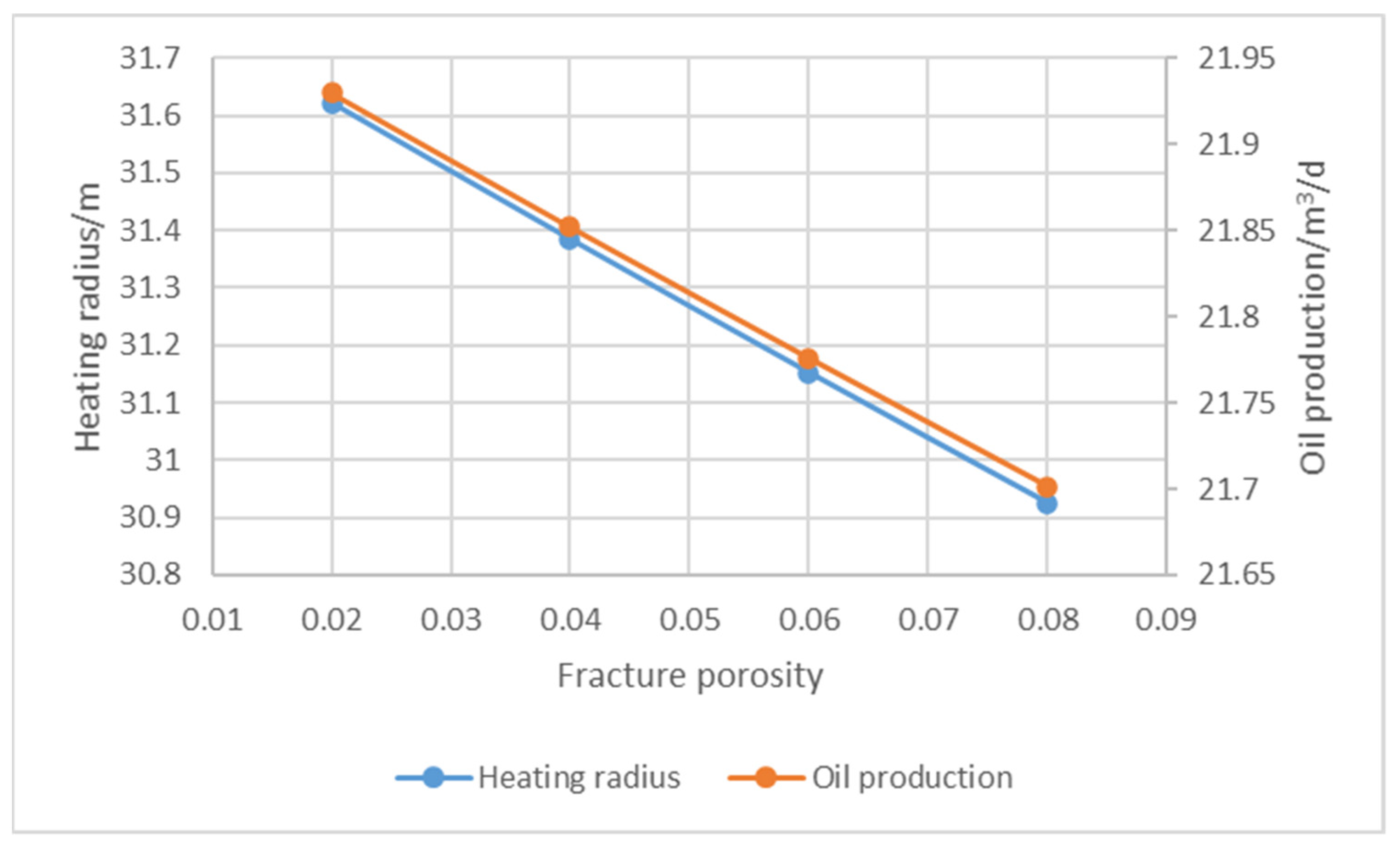
In accordance with the change of production with fracture density, the production decreases with the increase of fracture porosity and the decrease of heating radius, as shown in Figure 5.
4. Conclusions
- (1)
- After fracturing and packing, the heating radius of the heated reservoir volume is smaller than that of the unfractured reservoir, and the additional heat absorption of the fracture system generated by fracturing and packing leads to the reduction of the thermal recovery effect.
- (2)
- Fracturing can effectively improve reservoir permeability and increase production in contrast with no fracturing treatments.
- (3)
- The thermal production capacity of fractured heavy oil reservoirs is mainly affected by the heating effect, namely the heating radius. With the increase of fracture density, the heating radius decreases and the production decreases. The increase of fracture porosity also leads to the decrease of the heating radius and the production.
Author Contributions
L.W.: Conceptualization, Methodology. Y.L. (Yang Li): Writing-Reviewing and Editing. Z.L.: Methodology. Y.L. (Yikun Liu): Writing-Original draft preparation. L.S.: Formal analysis. Y.L. (Yunshu Lv): Validation. All authors have read and agreed to the published version of the manuscript.
Funding
This research was funded by: 1. Key R & D projects in Heilongjiang Province: research and development of key technologies for stability control of hydrate replacement mining and intelligent flow control device (gz20210015); 2. Joint guidance fund project in Heilongjiang Province: research on sand production mechanism of “phase change-pore-flow” synergistic control hydrate reservoir (lh2021e017).
Institutional Review Board Statement
Not applicable.
Informed Consent Statement
Not applicable.
Data Availability Statement
Data is contained within the article.
Acknowledgments
The authors are grateful for the financial support by Key R & D projects (gz20210015) and Joint guidance fund project (lh2021e017).
Conflicts of Interest
The authors declare that they have no known competing financial interests or personal relationships that could have appeared to influence the work reported in this paper.
References
- Cil, M.; Reis, J.C.; Miller, M.A.; Misra, D. An Examination of Countercurrent Capillary Imbibition Recovery from Single Matrix Blocks and Recovery Predictions by Analytical Matrix/Fracture Transfer Functions. In Proceedings of the SPE Annual Technical Conference and Exhibition, New Orleans, LA, USA, 27–30 September 1998; p. 49005. [Google Scholar]
- Dutra, T.V.; Aziz, K. A New Double-Porosity Reservoir Model for Oil/Water Flow Problems. SPE Reserv. Eng. 1992, 7, 419–425. [Google Scholar] [CrossRef]
- Mousavi, S.M.; Masoudi, R.; Ataei, A. Evaluation of Steam Flooding and Cyclic Steam Stimulation (CSS) for a Fractured Carbonate Heavy Oil Reservoir. In Proceedings of the IPTC 15454, International Petroleum Technology Conference, Bangkok, Thailand, 7–9 February 2012. [Google Scholar]
- Hao, L. Research on Reasonable Technology Policy of Steam Huff and Puff in Fractured Heavy Oil Reservoir. Graduation Thesis, China University of Geosciences, Beijing, China, 2015. [Google Scholar]
- Mohammadi, S.; Ehsani, M.R.; Nikookar, M.; Sahranavard, L.; Garakani, A.S. Study of steam injection in a fractured carbonate heavy oil reservoir in Iran. In Proceedings of the SPE Heavy Oil Conference Canada, Calgary, AB, Canada, 12–14 June 2012; p. 144943. [Google Scholar]
- Van Heel, A.P.; van Dorp, J.J.; Boerrigter, P.M. Heavy-oil recovery by steam injection in fractured reservoirs. In Proceedings of the SPE Symposium on Improved Oil Recovery, Tulsa, OK, USA, 19–23 April 2008; p. 113461. [Google Scholar]
- Marx, J.W.; Langenheim, R.H. Reservoir heating by hot fluid injection petroleum transactions. Trans. AIME 1959, 216, 312–315. [Google Scholar] [CrossRef]
- Carslaw, H.S.; Jaeger, J.C.; Ingersoll, L.R.; Zobel, O.J.; Ingersoll, A.C.; Van Vleck, J.H. Conduction of Heat in Solids and Heat Conduction. Phys. Today 1948, 1, 24. [Google Scholar] [CrossRef]
- Boberg, T.C. Calcalation of the Production Rate of a Thermally Stimulated Well. J. Pet. Technol. 1966, 18, 1613–1623. [Google Scholar] [CrossRef]
- Gontijo, J.E.; Aziz, K. A Simple Analytical Model for Simulating Heavy Oil Recovery by Cyclic Steam in Pressure-Depleted Reservoirs. Texas. In Proceedings of the SPE Annual Technical Conference and Exhibition, Houston, TX, USA, 16–19 September 1984; p. 13037. [Google Scholar]
- Wenzhang, L. Heavy Oil Steam Injection Thermal Recovery Engineering; Beijing Petroleum Industry Press: Beijing, China, 1997; pp. 107–124. [Google Scholar]
- Jianguo, W.; Yueming, C. A new model for predicting steam throughput. Pet. Explor. Dev. 1997, 24, 53–56. [Google Scholar]
Figure 1.
Thermal recovery model after formation fracturing and packing.

Figure 2.
Curve of heating radius with time.

Figure 3.
Fracturing affects production.

Figure 4.
Fracture density vs. heating radius.

Figure 5.
The influence of fracture porosity on production and heating radius.

Table 1.
Model calculation parameters.
| Reservoir Pressure/MPa | Bottomhole Flowing Pressure/MPa | Thermal Conductivity of Overburden and Underlying/ | Thermal Conductivity of rock/ | Fracture Porosity | Matrix Porosity | Heat Capacity of Overburden and Underlying/ |
| 20 | 12 | 145.7 | 149.5 | 0.02 | 0.2 | 2400 |
| Heat Capacity of Rock/ | Volumetric Heat Capacity of Oil/ | Volumetric Heat Capacity of Water/ | Pay Zone Thickness/m | Initial Reservoir Temperature/°C | Gas Injection Rate/kg/h | Thermal Conductivity of Oil/ |
| 2320 | 1900 | 4200 | 20 | 60 | 6000 | 10 |
| Thermal Conductivity of Water/ | Matrix Permeability/ | Fracture Permeability/ | Oil Saturation | Water Saturation | Steam Injection Temperature/°C | |
| 50 | 0.02 | 16.7 | 0.6 | 0.6 | 300 |
Publisher’s Note: MDPI stays neutral with regard to jurisdictional claims in published maps and institutional affiliations. |
© 2021 by the authors. Licensee MDPI, Basel, Switzerland. This article is an open access article distributed under the terms and conditions of the Creative Commons Attribution (CC BY) license (https://creativecommons.org/licenses/by/4.0/).
Share and Cite
MDPI and ACS Style
Wang, L.; Li, Y.; Li, Z.; Liu, Y.; Song, L.; Lv, Y. Production Calculation Model of Thermal Recovery after Hydraulic Fracturing and Packing in Tight Reservoir. Processes 2021, 9, 2226. https://doi.org/10.3390/pr9122226
AMA Style
Wang L, Li Y, Li Z, Liu Y, Song L, Lv Y. Production Calculation Model of Thermal Recovery after Hydraulic Fracturing and Packing in Tight Reservoir. Processes. 2021; 9(12):2226. https://doi.org/10.3390/pr9122226
Chicago/Turabian StyleWang, Long, Yang Li, Zhandong Li, Yikun Liu, Laiming Song, and Yunshu Lv. 2021. "Production Calculation Model of Thermal Recovery after Hydraulic Fracturing and Packing in Tight Reservoir" Processes 9, no. 12: 2226. https://doi.org/10.3390/pr9122226
Note that from the first issue of 2016, this journal uses article numbers instead of page numbers. See further details here.