
Processing Technologies for Crisis Response on the Example of COVID-19 Pandemic—Injection Molding and FFF Case Study


1
Centre for Advanced Technologies, Adam Mickiewicz University in Poznań, Uniwersytetu Poznańskiego 10, 61-614 Poznań, Poland
2
Faculty of Chemistry, Adam Mickiewicz University in Poznań, Uniwersytetu Poznańskiego 8, 61-614 Poznań, Poland
3
Faculty of Mechanical Engineering, Bialystok University of Technology, Wiejska 45C, 15-351 Białystok, Poland
*
Author to whom correspondence should be addressed.
Processes 2021, 9(5), 791; https://doi.org/10.3390/pr9050791
Submission received: 24 March 2021
/
Revised: 26 April 2021
/
Accepted: 26 April 2021
/
Published: 30 April 2021
(This article belongs to the Special Issue Process Control and Smart Manufacturing for Industry 4.0)
Abstract
:The paper presents a comparison of two methods of manufacturing utility objects made of plastics, applied to the emerging immediate need in the field of quick provision of personal protective equipment for medical services. The traditional processing method, which is injection molding (IM), and a modern rapid prototyping method, which is fused filament fabrication (FFF) 3D printing, were compared in terms of unit costs and production possibilities at various timeframes. The paper presents the effects of launching two production processes of protective helmets (face shields) using the example of real cases implemented ad hoc during the epidemic development. The implementation of the protective helmet production project based on polyamide-6 processing showed the real possibilities of quickly launching the rapid production of protective equipment with the aid of mold injection technology.
1. Introduction
The COVID-19 epidemic has caused a sharp increase in the demand for individual personal protective equipment, such as masks and protective helmets, on an unprecedented scale. Supply options have been significantly limited by the travel restrictions introduced to combat the pandemic. In addition, the production capacity in most countries for these protective measures was not adapted to the existing demand, which resulted in the need for non-standard solutions and small-batch processes requiring minimal set-up preparations. Currently, the development of new technologies driven by the 4th generation industrial revolution results in the development and application of new solutions increasingly based on additive technologies [1], both in the media area and in the academic world. Among the key technologies are additive techniques, popularly called 3D printing, which have been developing dynamically for over a decade, when the patent protections developed by the creators of the technology expired [2]. Initially, this technology did not arouse much interest—in the Gartner report from 2012 it was included in the area of the so-called ‘Trough of Disillusionment’ [3]. However, its development was so rapid that already in 2013 this statement changed and in 2015 Gartner published a separate report dedicated to 3D printing technology [4]. According to Gartner’s estimates, by 2021 as many as 20% of key global companies would create departments specializing in the application and use of 3D printing. We are already witnessing the intensive creation of start-ups related to this particular branch of the industry, improvement of 3D printers (ever better parameters and printing possibilities), and the emergence of new printing techniques and improvement of existing techniques. Currently, additive technologies can be divided into: photochemical (digital light processing (DLP) [5], stereolithography (SLA) [6,7,8]), laser-mediated selective laser sintering (SLS) [9], thermal fused deposition modeling/fused filament fabrication (FDM/FFF) [10,11] or laminated object manufacturing (LOM) [12].
Nowadays, there are still serious concerns about 3D printing techniques regarding the quality of produced objects, the significantly high process failure rate, or significantly higher unit production time and cost when compared to mature production processes, such as injection molding. Nevertheless, there are products in which the functionality itself becomes more important and constitutes the essence of the product, which means the visual quality ceases to be of decisive importance. In such cases, starting production can be much faster and cheaper. Examples of such products are the components of protective face shields. Such products, especially in the event of an exceptional situation in a global pandemic, are faced with two requirements: they are needed in high volumes and in a short delivery time, and their main function is protection against deadly microorganisms.
With the abovementioned elements in mind, the authors attempted to compare two extremely differently characterized techniques—injection molding and FFF 3D printing. Calculations were made to provide a simulation for a comparison of these two methods under different conditions (time of process run (see Figure 1), single- and multiple-socket forms for IM, single appliance vs. printer farm for FFF). The purpose of this comparison is to show the possibility of quick production of finished products by an industrial method without the need to use rapid prototyping techniques. It is a special case of the injection molding process, in which the visual quality is a negligible aspect in a situation determined by the function of the product. In other words, when it becomes more important to provide protection against the pathogenic effects of the surrounding environment, the visual quality of the products ceases to matter at a critical level, especially in a global pandemic situation. The problem analysis allowed for a rational response towards the pandemic crisis and a quick launch of production of protective helmets for Polish medical services, schools, and universities within the infrastructure of Centre for Advanced Technologies (AMU).
2. State of the Art
2.1. Literature Review of FFF 3D Printing
Along with the rapid development of machines dedicated to any process from the vast group of 3D printing techniques, it becomes necessary to design new materials that will allow the improvement of key parameters such as: layer-to-layer adhesion, print integrity and sealing, or other performance parameters of the material. The traditional industry is still approaching this subject with distance and caution, using incremental technologies mainly in the area of design or rapid prototyping, mainly due to the precise mapping of the model geometry and the possibility of obtaining complex shapes, while the production process of high-quality and accuracy products is still based on subtractive technologies, such as CNC machining [13].
3D printing has many features that constitute an advantage and improvement over traditionally used techniques, primarily:
- No need to design and make a tool, e.g., an injection mold—it allows you to save time and avoid high costs of expensive tools—especially important in small-lot production or in the case of a model consisting of several different elements, where traditional techniques would require the use of more than one mold or a complex supply chain [14].
- Personalized products are an example—production of models for a specific application, tailored to the user’s preferences, along with quick model optimization—especially in the sports industry or in industrial use in maintenance. 3D printing gives the possibility of producing spare parts for machines directly in the plant, which significantly contributes to reduction of production losses related to equipment stoppage, waiting for transport, etc. [15,16].
- The possibility of constructing complex, non-standard models with varying shapes and arrangement of planes/curves, as well as selected internal geometry (the object may have a full or openwork filling of a different arrangement), impossible or difficult to obtain with traditional techniques, as well as the possibility of changing the model or improving it at any time of production [14].
- Launching the production cycle immediately after the design stage, usually from a few hours to two days [17].
The versatility and availability of the method makes it applicable in large production plants, micro-enterprises or by an individual customer [18], and equipment is relatively cheap when compared to standard industrial processing equipment, e.g., injection molding machines [17].
Despite the many advantages of FFF technology, it has many pitfalls, either remaining to be solved or constituting dead-ends associated with the technology concept itself. The biggest shortcomings of the FFF and relating techniques include:
- Increased energy consumption per product unit mass—3D printing technologies require significant amounts of energy to apply a thin layer of material each time [19].
- Increased waste production related to factors resulting from the technology itself (unsuccessful prints, supports printing, post-processing); currently there is a significant problem of plastic waste production and the recycling thereof, which also applies to materials used for 3D printing. The popular PLA, which despite being considered ‘bio-friendly’, is not effectively recycled or composted as of today [20,21].
- Increased processing time per production unit increases the likelihood of a process fatal error [24].
- Lower mechanical strength, especially in the Z axis, resulting from, among others, poor layer-to-layer (interlayer) adhesion, the presence of air gap between the layers, and inter-layer distortion—many high-strength materials still do not meet this criterion [25]; fibre‑reinforced compositions were proposed as a solution for some of these issues; however, this method is still not perfect and causes problems related to the formation of voids between the layers, poor adhesion of fibres and matrix, and greater wear on the nozzle [26].
- The number of currently available materials for FFF printing is still limited, and each individual polymer has its own specificity of work, which can be problematic to control. Most of the thermoplastics on the market are dedicated to traditional processing techniques, such as injection/extrusion/blow molding, and the modification of plastics for FFF is still a niche topic explored mainly in the scientific community.
- For materials with high processing shrinkage, there is a need to heat the table or the entire printer chamber, which significantly increases the energy consumption per production unit [19].
- Noticeably lower visual quality of products, with the exception of systems with a very small nozzle diameter and parameters optimized for a specific printing material and product, which increases both the preparation time for printing and the printing process itself. Alternatively, the product requires additional post-processing [27].
One of the weaknesses of printing with the FFF technique is, above all, the lack or insufficient amount and availability of construction materials that would allow the elimination of poor characteristics of the finished models. In addition, the choice of materials in the context of the types of polymer matrices and their grades is limited. Improvement of the materials for printing is expected mainly in the processing and utility areas, e.g., increased interlayer adhesion by better melting behaviour of the material (temperature–rheology optimization), thus also increasing the mechanical strength, improving flexibility while maintaining other parameters, increasing the integrity of the layers (reducing air pockets), and water resistance. Finally, an improvement of aesthetic values is sought, which will contribute to saving time and reducing costs related to post-processing (ultimately it should be eliminated, so the detail obtained by 3D printing would be used “as received”).
Despite the many advantages and the increasing popularity of additive techniques, they are still far from being perfect. In many respects they cannot replace traditional techniques, and it is even advisable to use well-known processing methods such as injection, calendering, extrusion, etc. Therefore, instead of considering additive technologies as a substitute for mature processing techniques, it is advisable to continue looking for new areas where the unique possibilities of 3D printing can be used to extend the use of traditional production processes. 3D printing can also be used in combination with traditional techniques, where the product is manufactured using a hybrid technique (overprinting, overmolding). In this approach, for example, the greater part of the detail, of a relatively large mass fraction (difficult to produce with the printing technique due to the weight or size and time of printer operation) and simple shapes, are injection-molded, while the part with smaller dimensions and geometry that makes it difficult to implement the injection process is made with a 3D printing technique, after which the parts are combined into a finished detail [28].
In addition, it should be noted that 3D printing becomes an unprofitable technique in a situation where there is a need to make large batches of products, even if their design is highly complicated and thus expensive or time consuming in comparison with tools/molds preparation. In such situations, it is more advantageous to use other options, e.g., injection molding. Despite expensive tools and machines, it becomes more profitable in large-scale and mass production due to short production cycles—counted in seconds or minutes.
3D printing is dedicated to the fabrication of individual products or small series of products, due to the long printing cycles counted in several hours. For this reason, 3D printing is an ineffective process, unsuitable for larger volumes of production. The “break-even point” parameter is calculated, i.e., the number of items at which it is economically viable to transfer production to a process with higher production efficiency, but with higher production implementation costs. In the case of 3D printing, the estimates give values up to 400 pieces, depending on the type of product and the parameters adopted for calculations [22]. With this in mind, it is believed that the future of 3D printing is assigned to single and non-standard applications, where it becomes unprofitable to produce an expensive injection mold for the production of individual, non-standard products. In such situations, the choice of 3D printing over different tool-dependent techniques becomes justified, as the cost of waiting several hours for the production of an unusual detail is lower than the production of an expensive mold.
Obtaining an element by injection molding requires designing an appropriate form, which is associated with 3D modelling processes; however, it is only the beginning of preparations for starting the process. Computer simulations with the use of specialized software are necessary to obtain the geometry of the mold that generates low polymer flow resistance, which facilitates the injection of the detail without defects, and also reduces mold wear, e.g., by cavitation or the abrasive effect of fillers in the polymer (especially important for aluminium molds) [29,30].
2.2. Additive Techniques Compared to the Injection Molding Method
The material for injection forming is usually one of the popular thermoplastics; additionally it can be reinforced with structural glass, carbon, Kevlar, aramid or natural fibres, as well as various mineral fillers. The injection process is a method used mainly in large-scale production (professional products, mass production). In the case of injection molding, it is not possible to freely improve the design after the mold production stage. The geometry of the product is also limited—with more complex shapes, the product must be divided into parts injected as independent details—3D printing in this area offers much more freedom due to the lack of a need for a form, from which it is necessary to remove a once produced detail. One of the greatest advantages of the process is its speed—the cycle time is usually from under half a minute up to several minutes, compared to printing, where the fabrication of a product unit usually takes from less than an hour up to several hours or days.
Injection molding itself, especially in recent years, has become considered as an engineering art [31,32].
In practical terms, the injection molding process has two main goals. The first is to obtain finished and quality products in the shortest time possible, in a fast reproducible and large-scale process. The second goal is the conscious control of the phenomena occurring in the liquid polymer melt [31,32,33].
The heart of the process is the tool—the injection mold. As of today, the design of injection molds and launching injection production is carried out with the inseparable aid of simulation techniques. MoldFlow or Moldex3D can be mentioned as the more well-known programs for this purpose [30,34,35,36].
Despite the use of modern computer simulations, starting a production of a new product, even nowadays, sometimes requires many hours of technological trials and subsequent tool corrections. However, the long period of starting production is not only due to technological problems related to the design of the tool (location of the injection point, the geometry of the gate and inlet channels, etc.), but the visual quality optimization of the final product which plays a large part here [31,37,38,39]. Most often, companies set very high quality criteria for products, which significantly extends the launch of production [29,31,39,40,41,42,43,44,45,46,47,48].
3. Materials and Methods
3.1. Materials and Methods for 3D Printing vs. Injection Molding Experiments
Two methods were used to produce protective face shields. The first one was FFF 3D printing, and the second one was the injection molding method. For FFF, an open-source PRUSA 3D model of the protective helmet was used. For injection molding, both the new helmet model and the required injection mold have been designed with SolidWorks software (for the technical drawing and 3D model Figures, see Supplementary Materials).
For the first processing method, FFF, the objects were printed with Dreamer printers with 230 × 150 × 140 mm printing space and double extruder printheads, using standard 1.75 mm filament. The face shields were printed using PET-G (Verbatim) filament. The optimization comprised testing different layer heights, number of shells, extruder temperature, and bed temperature. Table 1 contains all parameters for optimized 3D printing process applied for this particular process.
The second process, that is injection molding, was carried out on an ENGEL e-victory 80/170 injection molding machine with a 25 mm screw, equipped with an aluminium single socket mold. The thermoplastic material used was a recyclate (regranulate) of PA6-GF15 (under the trade name Tarnamid T-27 GF15, Grupa Azoty S.A.), reinforced with 15% w/w glass fibre, generously provided by STER INSTITUTE company (Poland). The process optimization required testing various temperature zone setting changes, heating and cooling the movable plate to different temperatures, adjusting intrusion time and the injection and holding pressure profiles. In addition, small adjustments of the mold gates and vents were required, which were done on the completed mold mounted on the injection molding machine during technological tests. The optimized parameters for injection molding were as follows: temperature profile of plastification unit, from feed to die: 250 °C, 255 °C, 255 °C, 270 °C, mold temperature: 60 °C stationary plate, 20 °C movable plate, max. injection time: 2.7 s, intrusion time 4.3 s, cooling time: 30 s, injection pressure: 1300 bar, holding pressure profile: 575 bar/0.5s, 675 bar/1s.
Mechanical tests of the materials were done in accordance to the norm EN ISO 527-2:1996. Dumbbell samples were prepared by either 3D printing or injection molding. The speed of traverse was set to 50 mm/min. A universal testing machine Instron 5969 was used. The Charpy impact test (with no notch) was performed on a Instron Ceast 9050 impact-machine according to ISO 179−1. For all the series, 10 measurements were performed.
The data are collected in the table of see Section 5.
3.2. Simulation Model
The calculation model was designed to simulate the most important production parameters, such as: unit production cost, total production volume vs. time, and unit production cost vs. total production volume. In order to achieve this, data on a variety of production parameters (e.g., tool cost, material cost, and unit production time, etc.) are collected in Table 2. Different scenarios were assigned for simulations, i.e., operating on a single FFF 3D printer, an FFF 3D printer farm, a single socket IM machine, or a multiple socket IM machine. These scenarios were chosen to discuss some production aspects, such as the total production output, production costs, or costs per production unit, when different production set-ups are applied, and how the changes of set-up affect these parameters (e.g., switching from a single FFF printer to a printer farm). Data such as the number of product units per 24 h, percentage of defective product units, and effective product unit output per 24 h were taken from our production tests made with a small 3D printing farm (10 pcs) for FFF, and an Engel injection molding machine for injection molding. Data on tools and designing were supplied by the industrial partner specialized in injection molding, STER INSTITUTE (Poland). Basics of the tool design and cost prediction may be found in the literature [49]. Equations (1)–(9) were assigned to run calculations.
For effective output per 24 h:
where d—% defective product units
oe = o * (1 − d/100%)
For cost per unit
where cm—Material cost [USD/kg]; mu—Product unit mass [g]
cu = cm * mu/1000
For no. of product units per 24 h
where o—Output [g/h]
ud = 24 * o/mu
For energy consumption per unit
where ed—Energy consumption per 24 h [kWh]; ud—No. product units per 24 h
eu = ed/ud
For energy consumption per 24 h
where p—Machine power* [kW]; wf—Work fraction
ed = 24 * p * wf
For fixed costs
where ct—Tool cost [USD]; cd—Design cost [USD]
cf = ct + cd
For machinery costs per day of production
where cma—Machinery costs [USD]
cmd = cma * 2/365
For machinery cost per unit a day
Cmu = cmd/oe
For total cost per unit
Cto = cu + ce + cmu
On the basis of these simple equations, the final model Equations (10)–(12) were assigned as follows:
For unit production costs vs. production run (see Figure 2)
where xd—days of production
Cud = (cf/xd + ud * cto)/ud
For the cumulative production volume vs. time (see Figure 3)
where n = 1 for 3D printing and 3D Farm printing; n = for Injection molding and Multiple socket injection molding
Vc = (xd − n) * oe
For the unit production cost vs. total production volume (see Figure 4)
where xu—units of production
Cuv = (cf + cto * xu)/xu
4. Process Set-Up and Simulation Purpose
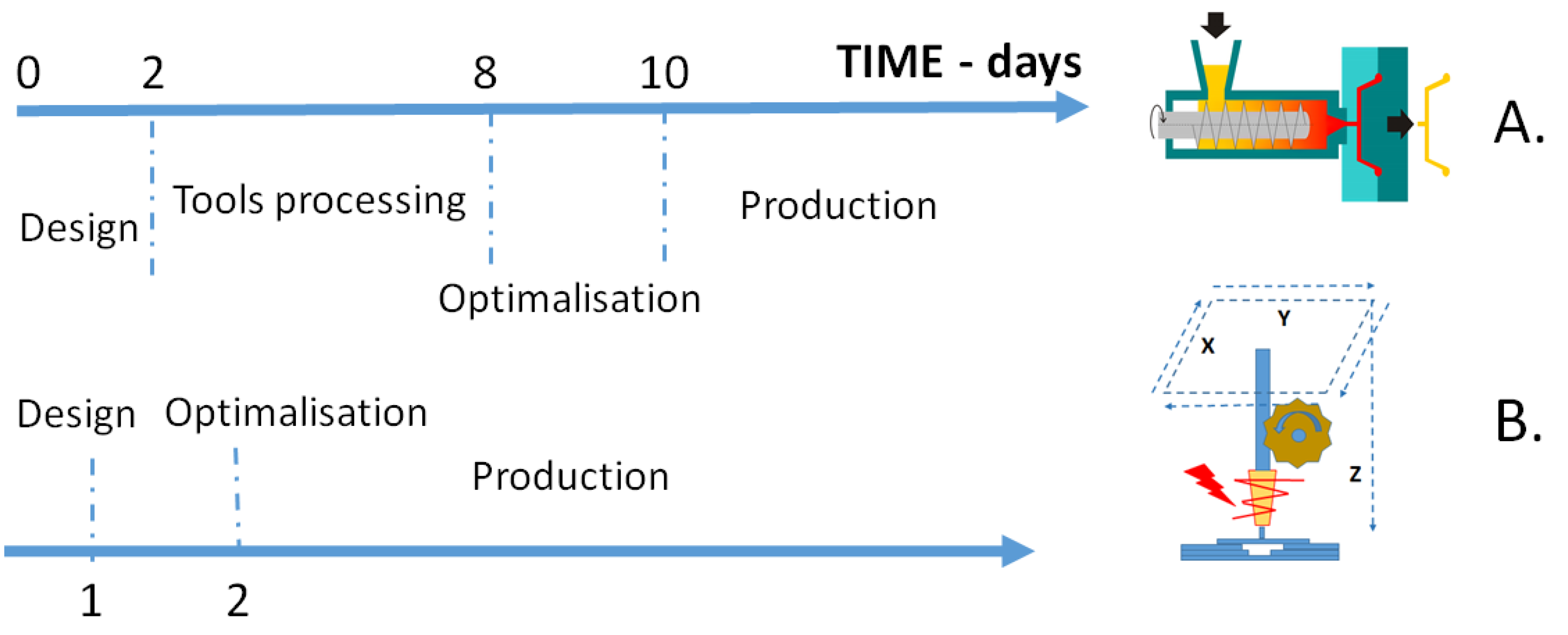
The main advantage of the FFF technology is the ease and speed of prototyping, which does not require the production of specialized tools in the form of molds. Most analyses state that the production process begins 1–2 days after “making a decision” (Figure 1B). However, the time of designing and optimizing the model is often omitted in the analyses and the time equal to 0 is assumed for this part of the process preparation chain, which is incorrect from the technological point of view and is purely a marketing approach. In our case, the production started within two days, which were needed to optimize the printing process towards process stability and product quality. In the case of the traditional technique, which is thermoplastic injection, the time from “making a decision” to starting production takes more than one week (under the most optimal conditions). In our case (real conditions during pandemic outbreak), the process was launched within 10 days before reaching full output (Figure 1A). This is due to the fact that from the moment of making the decision up to launching the production, it is necessary to carry out preparations such as:
- (1)
- Designing combined with computer simulation of the injection process—this stage may take up to several days depending on the complexity of the product. Despite the fact that it requires time, it is a much cheaper operation than direct injection tests after designing the tool and subsequent reworking of a wrongly designed tool. In the case of making a tool without simulations, this stage often ends with the production of a new tool, the actual geometry of which has been determined in technological trials.
- (2)
- Technological tests after making a tool, the critical elements of which have been verified in a computer simulation—this stage may be very short, in the order of hours or, in an unfavorable situation, up to several days. The optimization time was also included (possible tool or process correction).
- (3)
- Production start-up—from an hour to several hours, assuming that in all previous stages the most satisfactory results were achieved. In relation to the injected product, injection tools are elements of large mass, have a precise structure and require specialist knowledge in the area of designing and operating the apparatus. In the absence of the latter, the period from the decision to the launch of production may be, in extremely unfavorable cases, up to 40–60 days for complex details to be produced.
The factors characterized above show the first feature that justifies the increasingly more and more popular use of incremental techniques—the speed of the process and little preparation needed. In addition, the investment outlays in the first phase of designing and starting the process are incomparably greater in the case of injection molding technology. For large-size objects with complex geometry, often requiring several separate processes, and thus also processing machines, the cost of tools can reach hundreds of thousands of dollars. Therefore, especially for small lot production, injection molding is much less cost effective compared to additive techniques.
As a part of activities supporting medical services during the COVID-19 epidemic in Poland, our team launched the process of manufacturing protective helmets. In the first phase of the epidemic, the production of the shields by 3D printing using FFF printers was very popular. The designs were available in an open-source format available online. Often, printer manufacturers shared their projects, such as the Czech company PRUSA. On the basis of this project, elements of protective gear were manufactured and sent to hospitals by individuals or research units. It was a measurable example of how the high flexibility and speed of FFF technology can contribute to mitigating the shortages of protective measures in the country. Our team, performing tests of manufacturing elements using the FFF technique, analyzed the functionality, durability, and performance properties of such objects made of plastics such as PET-G or PLA. With such a high demand for personal protective equipment, the printing time of one unit was too long and the results were unsatisfactory. It was therefore decided to launch an alternative project of manufacturing these by an injection molding method. The reasons for this decision were the following factors: (a) material cost analysis, (b) unsatisfactory process time of FFF, (c) unsatisfactory print quality, (d) unsatisfactory functional features and ergonomics of open-source projects.
For the purposes of the simulation, data on operational, cost and performance parameters of selected processing methods were collected. The analysis included both the work of one tool (printer, single-socket mold, etc.), as well as the tool sets, such as the printer farm or a multi-socket mold (Table 2). These scenarios were selected to compare the aspects of different production approaches side by side and stress their limitations or shortcomings. Due to the significant technological differences between the FFF and IM techniques, it was not possible to use the same materials. Plastics dedicated to injection molding and FFF differ in terms of parameters and availability—it is not possible to obtain the same material for both techniques. As a result, material type and cost are different for the simulations provided for these two techniques and favour of injection molding. Per unit of mass, plastics intended for 3D printing are also much more expensive, which significantly increases the unit price of the product in case of FFF 3D printing. It is necessary to note that the project was carried out at the peak of the first wave of the COVID-19 pandemic outbreak in Poland and Europe, when the supplies of specialized materials were suspended, and the work was carried out using on-site available materials for the processing techniques discussed. The simulation presented in the manuscript shows the minimum time in which the discussed processing techniques can be implemented, which has been proven in real operating conditions.
5. Discussion
A product design must always be compatible with the technique applied for the manufacturing process. To enable 3D printing of the protective helmet in household conditions, there was a requirement for the open-source design that could accommodate the most popular 3D printer bed sizes (it could not exceed the printing dimension limitations of common 3D printers for amateur use). For this reason, the protective helmet body of the open-source design was small and barely comfortable, and it was also not very stable on the user’s head (see Supplementary Materials, Figure S1). In addition, 3D printed pieces usually required some post-processing, namely sanding, as rough surfaces were often generated during printing, which was another issue of the user comfort and it extended the time of production. Furthermore, due to the abovementioned dimensional limitations, the FFF design of the helmet body required a lot of elastic rubber band to accommodate the user head, which quickly resulted in a national shortage of this material, as it was needed to secure most of the simple design protective helmets or face shields. Our design of the protective helmet body dedicated for injection molding addressed this issue: the support band of the helmet was elongated so that it would match the head circumference better and therefore minimize the amount of required rubber band, and it was easily adjustable with simple tools, by cutting off the excess of the plastic band (see Supplementary Materials, Figure S7). In addition, from a technical point of view, when it comes to 3D printing by FFF technique and designing the object models dedicated for FFF printing, sagging is often an issue for objects with overhanging details. To avoid this, a 3D model may be provided with additional supports or redesigned so that the overhangs are eliminated by additional geometric shapes, or smoothed/reduced. This can be seen on the example of mounting pins of the protective helmet body, when comparing the FFF-printed object and the injection-molded one (see Supplementary Materials, Figures S1–S3).
In terms of unit costs, the multi-cavity injection molding technology does not have any competition (Figure 2). Calculations have shown that only for large farms of 3D printers, the unit cost can be competitive compared to a single-cavity injection mold over a period of a couple of days. Large printer farms are characterized by flat cost characteristics from the first days of starting production, which shows that only for large printer units they can be a tool for mass production. The analysis of the cumulative value of production (Figure 3) showed a relatively high competitiveness of a large printer farm in relation to a single-cavity injection molding process. The performance curves for these two manufacturing tools intersect around 10–15 days after the decision to start a given production. Comparative data on the efficiency values for a given technology allow for a precise assessment of the appropriate selection of technology for the purpose of its application. The calculations (Figure 4) show that the techniques usually used for rapid prototyping work well for short-term production. Perhaps that is why in the first phase of the pandemic, in the absence of forecasts about its possible development, much attention was paid to simple and accessible techniques such as FFF printing. This made it possible to meet many basic needs. In the later period, a gradual switch of production plants from the current production over to the missing elements needed to save human life and health was observed. This has often happened without meeting all material performance and certification standards that existed before the pandemic. Increasing the production capacity resulted in a decline in the interest in products manufactured with additive techniques due to their poor quality (Figure 5). In addition, injection molding provided products of much higher mechanical performance when compared to FFF process, as we verified the processes experimentally (Table 3). It can be seen that the large difference is based on the type of material used, but this fact also emphasizes the benefits of injection molding as a high performance process, as it can utilize materials with which FFF process would be impossible to carry out by the means of currently available 3D printers.
While in the first weeks of the pandemic, economic factors were not of primary importance, along with its development a need arose to rationalize resources for the production and optimize the use of raw materials. In order to more precisely approximate the economic profitability threshold, i.e., in the conditions of a normally functioning economy, the basic factor determining the use of a given processing technique, the change in the cost of manufacturing a product unit was compared in respect to its growing production. For the compared manufacturing techniques, the differences are significant and noticeable, especially for the first few thousand units of the product produced (Figure 4). Rapid prototyping techniques show their advantage for series up to several thousand elements, while the advantages of classic techniques are revealed in larger numbers. Taking into account the choice of manufacturing technology in emergency situations, the quality of the final detail is also of secondary importance. However, one should be aware of the advantages and disadvantages of the method used. Figure 5A–H shows the details of the products observed microscopically.
The defects of the printed objects, in particular the areas of material discontinuities (Figure 5F,H), make their usefulness in medical applications far below satisfactory. Dirt and bacteria can collect in the cavities, and the porosity makes the object a breeding ground for microorganisms. Furthermore, as these objects are elastic and meant to deform in order to accommodate the user’s head, the material discontinuities may cause cracks and splitting while using the object or during helmet assembly. Such behaviour was observed during the tests of the 3D-printed protective helmet body pieces (Figure S1, Supplementary Materials). In addition, the reduced mechanical parameters of the test specimens were measured when compared to the technical reference (Table 3). The described examples of the use of elements made of plastics in crisis conditions did not require the use of plastics with approval for medical applications. The pandemic crisis has shown that it is essential to have manufacturing tools to respond when the supply chain is interrupted or disrupted. In such a situation, the availability of systems such as 3D printer farms can prevent a shortage of basic personal protective equipment. In such situations, product certification and appropriate permits become a secondary consideration, and the priority is to save human lives and ensure the collective safety of the population.
6. Conclusions
The conducted project and analyses supported by the performed simulation allowed us to collect and quantify the most important aspects which are the limitations of the FFF technique. In order for the 3D printing technology to compete more effectively with traditional methods such as thermoplastics mold injection, two basic limiting conditions must be met simultaneously or independently—increasing the speed of the process 6–10 times and reducing defect formation in the interlayer areas, which cause poor object quality, reproducibility issues, and mechanical failures. Nevertheless, large groups of FFF printers (printer farms) can successfully compete with injection machines for low-volume solutions, if a satisfactory quality of printed objects is provided. Most importantly, it should be pointed out that the FFF technique is a viable method of response to a sudden crisis situation, as was the case with the COVID-19 pandemic, as it allowed for providing the basic needs for personal protection in the first weeks of the pandemic. Individual users contributed their products to public entities, such as hospitals, which gave the time needed to launch production lines of high-quality products with the application of mature processing methods.
Supplementary Materials
The following are available online at https://www.mdpi.com/article/10.3390/pr9050791/s1, Table S1: Project chronology, Figure S1: Protective helmet body made with FFF 3D printing technique, Figure S2: Technical drawing of protective helmet body design for Injection molding production method, Figure S3: 3D model of protective helmet body design for Injection molding production method, Figure S4: technological tests and optimization of injection molding, Figure S5: Protective helmet fully assembled and tested for the comfort of using, Figure S6: The protective helmet detail as received during injection molding process (with sprue remaining), Figure S7 : Correction of the protective helmet band for the head size of a particular user, Figure S8: The technological team dealing with the study of the production process of the protective helmets.
Author Contributions
Conceptualization, R.E.P. and B.S.; methodology, R.E.P., B.S. and D.B.; software, R.E.P.; validation, R.E.P. and M.J.; investigation, B.S., D.B. and R.E.P.; resources, B.S.; data curation, R.E.P.; writing—original draft preparation, B.S., D.B., R.E.P. and M.J.; writing—review and editing, visualization, R.E.P.; supervision, B.S.; project administration, B.S., funding acquisition, B.S. All authors have read and agreed to the published version of the manuscript.
Funding
This research was funded by National Centre for Research and Development, Poland, grant no. LIDER/01/0001/L-10/18/NCBR/2019 and from the resources Adam Mickiewicz University (Poland).
Institutional Review Board Statement
Not applicable.
Informed Consent Statement
Not applicable.
Data Availability Statement
The data provided for the calculation model were either obtained experimentally from on-site tests made with a small 3D printing farm (10 pcs) for FFF, and an Engel injection molding machine for injection molding. Data on tools and designing were supplied by the industrial partner specialized in injection molding, STER INSTITUTE (Poland).
Acknowledgments
The authors thank Bronislaw Marciniak (AMU) and Marek Nawrocki (AMU) for entrusting the task of producing protective shields. Many thanks to the STER company for technological support of the conducted research. We express our gratitude to the key industrial partner—STER INSTITUTE and CEO Maciej Szymanski for support in the field of injection mold manufacturing, injection mold design, modelling, assembly, and technical support during technological tests, as well as providing PA-6 material for injection molding. Thanks to Krzysztof J. Kurzydlowski for consultations in the field of material engineering. Many thanks to ERGIS company, Dąbrowskiego 2, Wąbrzeźno, Poland, for donating PET film for the production of protective shields.
Conflicts of Interest
The authors declare no conflict of interest.
References
- Fawcett, S.E.; Waller, M.A. Supply chain game changers—mega, nano, and virtual trends—and forces that impede supply chain design (i.e., building a winning team). J. Bus. Logist. 2014, 35, 157–164. [Google Scholar] [CrossRef]
- Gibson, I.; Rosen, D.W.; Stucker, B. Additive Manufacturing Technologies; Springer: Berlin/Heidelberg, Germany, 2010. [Google Scholar]
- LeHong, H.; Fenn, J. Emerging Technologies Hype Cycle; Report; Gartner: Stamford, CT, USA, 2012. [Google Scholar]
- Baasiliere, P.; Shanler, M. Hype Cycle for 3D Printing; Report; Gartner: Stamford, CT, USA, 2015. [Google Scholar]
- Valentinčič, J.; Peroša, M.; Jerman, M.; Sabotin, I.; Lebar, A. Low Cost Printer for DLP Stereolithography. J. Mech. Eng. 2017, 63, 559–566. [Google Scholar] [CrossRef] [Green Version]
- Schmidleithner, C.; Kalaskar, D.M. Stereolithography. In 3D Printing; Cvetković, D., Ed.; IntechOpen: London, UK, 2018; pp. 1–22. [Google Scholar]
- Kataria, A.; Rosen, D.W. Building around inserts: Methods for fabricating complex devices in stereolithography. Rapid Prototyp. J. 2001, 7, 253–262. [Google Scholar] [CrossRef]
- Bártolo, P.J.; Gibson, I. History of Stereolithographic Processes; International Journal of Scientific and Research Publications; Centre for Rapid and Sustainable Product, Polytechnic Institute of Leiria: Leiria, Portugal, 2018; Volume 8, ISSN 2250-3153. [Google Scholar]
- Fina, F.; Goyanes, A.; Gaisford, S.; Basit, A.W. Selective laser sintering (SLS) 3D printing of medicines. Int. J. Pharm. 2017, 529, 285–293. [Google Scholar] [CrossRef] [Green Version]
- Upcraft, S.; Fletcher, R. The rapid prototyping technologies. Assem. Autom. 2003, 23, 318–330. [Google Scholar] [CrossRef]
- Novakova-Marcincinova, L.; Kuric, I. Basic and Advanced Materials for Fused Deposition Modeling Rapid Prototyping Technology. Manuf. Ind. Eng. 2012, 11, 24–27. [Google Scholar]
- Kalmanovich, G. “Curved-Layer” Laminated Object Manufacturing. In Proceedings of the 1996 International Solid Freeform Fabrication Symposium, Austin, TX, USA, 12–14 August 1996. [Google Scholar]
- Vinodh, S.; Sundararaj, G.; Devadasan, S.R.; Kuttalingam, D.; Rajanayagam, D. Agility through rapid prototyping technology in a manufacturing environment using a 3D printer. J. Manuf. Technol. Manag. 2009, 20, 1023–1041. [Google Scholar] [CrossRef]
- A Third Industrial Revolution. The Economist, 21 April 2012.
- Khajavi, S.H.; Partanen, J.; Holmström, J. Additive manufacturing in the spare parts supply chain. Comput. Ind. 2014, 65, 50–63. [Google Scholar]
- Murr, L.E.; Gaytan, S.M.; Ramirez, D.A.; Martinez, E.; Hernandez, J.; Amato, K.N.; Shindo, P.W.; Medina, F.R.; Wicker, R.B. Metal fabrication by additive manufacturing using laser and electron beam melting technologies. J. Mater. Sci. Technol. 2012, 28, 1–14. [Google Scholar] [CrossRef]
- Berman, B. 3-D printing: The new industrial revolution. Bus. Horiz. 2012, 55, 155–162. [Google Scholar] [CrossRef]
- Rayna, T.; Striukova, L. From rapid prototyping to home fabrication: How 3D printing is changing business model innovation. Technol. Forecast. Soc. Chang. 2016, 102, 214–224. [Google Scholar] [CrossRef] [Green Version]
- Yoon, H.-S.; Lee, J.-Y.; Kim, H.-S.; Kim, E.-S.; Shin, Y.-J.; Chu, W.-S.; Ahn, S.-H. A Comparison of Energy Consumption in Bulk Forming, Subtractive, and Additive Processes: Review and Case Study. Int. J. Precis. Eng. Manuf. Green Technol. 2014, 1, 261–279. [Google Scholar] [CrossRef]
- Sanchez, F.A.C.; Boudaoud, H.; Hoppe, S.; Camargo, M. Polymer recycling in an open-source additive manufacturing context: Mechanical issues. Addit. Manuf. 2017, 17, 87–105. [Google Scholar] [CrossRef]
- Dobrosielska, M.; Przekop, R.E.; Sztorch, B.; Brząkalski, D.; Zgłobicka, I.; Łępicka, M.; Dobosz, R.; Kurzydłowski, K.J. Biogenic Composite Filaments Based on Polylactide and Diatomaceous Earth for 3D Printing. Materials 2020, 13, 4632. [Google Scholar] [CrossRef] [PubMed]
- Franchetti, M.; Kress, C. An economic analysis comparing the cost feasibility of replacing injection molding processes with emerging additive manufacturing techniques. Int. J. Adv. Manuf. Technol. 2017, 88, 2573–2579. [Google Scholar] [CrossRef]
- Atzeni, E.; Salmi, A. Economics of additive manufacturing for end-usable metal parts. Int. J. Adv. Manuf. Technol. 2012, 62, 1147–1155. [Google Scholar] [CrossRef]
- Drizo, A.; Pegna, J. Environmental Impacts of Rapid Prototyping: An Overview of Research to Date. Rapid Prototyp. J. 2006, 12, 64–71. [Google Scholar] [CrossRef]
- Sood, A.K.; Ohdar, R.K.; Mahapatra, S.S. Parametric appraisal of mechanical property of fused deposition modelling processed parts. Mater. Des. 2010, 31, 287–295. [Google Scholar] [CrossRef]
- Heidari-Rarani, M.; Rafiee-Afarani, M.; Zahedi, A.M. Mechanical characterization of FDM 3D printing of continuous carbon fiber reinforced PLA composites. Compos. Part B Eng. 2019, 175, 107147. [Google Scholar] [CrossRef]
- Ngo, T.; Kashani, A.; Imbalzano, G.; Nguyen, K.; Hui, D. Additive manufacturing (3D printing): A review of materials, methods, applications and challenges. Compos. Part B Eng. 2018, 143, 172–196. [Google Scholar] [CrossRef]
- Boros, R.; Rajamani, P.K.; Kovács, J.G. Combination of 3D printing and injection molding: Overmolding and overprinting. Express Polym. Lett. 2019, 13, 889–897. [Google Scholar] [CrossRef]
- Gordon, J., Jr. Total Quality Process Control for Injection Molding; John Wiley & Sons: Hoboken, NJ, USA, 2010. [Google Scholar]
- Huamin, Z. Computer Modeling for Injection Molding: Simulation, Optimization, and Control; John Wiley & Sons: Hoboken, NJ, USA, 2013. [Google Scholar]
- Kent, R. Energy Menagement in Plastics Processing. Strategies, Targets, Techniques and Tools; Plastics Information Direct: London, UK, 2013. [Google Scholar]
- Jałbrzykowski, M. Wybrane Zagadnienia Procesu Wtryskiwania Biopolimerów do Zastosowań Technicznych na Przykładzie Polilaktydu (PLA); Wydawnictwo Polskiego Towarzystwa Inżynierii Rolniczej, Inżynieria Rolnicza: Kraków, Poland, 2019. [Google Scholar]
- Jałbrzykowski, M.; Obidziński, S. A comparison of the breaking strength of samples of parts made from pure and regrind polypropylene. J. Res. Appl. Agric. Eng. 2017, 62, 55–58. [Google Scholar]
- Rytka, C.; Lungershausen, J.; Kristiansen, P.M.; Neyer, A. 3D filling simulation of micro- and nanostructures in comparison to iso- and variothermal injection moulding trials. J. Micromech. Microeng. 2016, 26, 065018. [Google Scholar] [CrossRef]
- Martowibowo, S.Y.; Kaswadi, A. Optimization and Simulation of Plastic Injection Process using Genetic Algorithm and Moldflow. Chin. J. Mech. Eng. 2017, 30, 398–406. [Google Scholar] [CrossRef]
- Rosato, D.V.; Rosato, D.V.; Rosato, M.G. Injection Molding Handbook; Springer Science & Business Media LLC: New York, NY, USA, 2000. [Google Scholar]
- Jałbrzykowski, M.; Obidziński, S.; Minarowski, Ł. Wpływ wybranych parametrów procesu wtryskiwania na wytrzymałość na rozciąganie detali z polilaktydu starzonych w środowisku płynu Sorensena. Przemysł Chem. 2017, 96, 1869–1872. [Google Scholar] [CrossRef]
- Kitayama, S.; Onuki, R.; Yamazaki, K. Warpage reduction with variable pressure profile in plastic injection molding via sequential approximate optimization. Int. J. Adv. Manuf. Technol. 2014, 72, 827–838. [Google Scholar] [CrossRef]
- Sykutera, D.; Czyzewski, P.; Kosciuszko, A.; Szewczykowski, P.; Wajer, L.; Bielinski, M. Monitoring of the injection and holding phases by using a modular injection mold. J. Polym. Eng. 2018, 38, 63–71. [Google Scholar] [CrossRef]
- Pruitt, L.A.; Chakravartula, A.M. Mechanics of Biomaterials: Fundamental Principles for Implant Design; Cambridge University Press: Cambridge, UK, 2011. [Google Scholar]
- Hatta, N.M.; Azlan, M.Z.; Shayfull, Z.; Roselina, S.; Nasir, S.M. Analysis of The Shrinkage at The Thick Plate Part using Response Surface Methodology. In Proceedings of the 3rd Electronic and Green Materials International Conference (EGM), Aonang Krabi, Thailand, 30 April 2017; p. 020152. [Google Scholar]
- Giret, A. Sustainability in manufacturing operations scheduling: A state of the art review. J. Manuf. Syst. 2015, 37, 126–140. [Google Scholar] [CrossRef]
- Fisher, J.M. Handbook of Molded Part Shrinkage and Warpage; Plastic Design Library, William Andrew Inc.: Norwich, CT, USA, 2003. [Google Scholar]
- Fernandes, C.; Pontes, A.J.; Viana, J.C.; Nobrega, J.M.; Gaspar-Cunha, A. Modeling of Plasticating Injection Molding—Experimental Assessment. Int. Polym. Process. 2014, 29, 558–569. [Google Scholar] [CrossRef]
- Diduch, C.; Dubay, R.; Li, W.G. Temperature control of injection molding. Part 1: Modeling and Identification. Polym. Eng. Sci. 2007, 44, 2308–2317. [Google Scholar] [CrossRef]
- Chil-Chyuan, K.; Wei-Hua, C.; Jia-Wei, Z.; Ysai, D.-A.; Cao, Y.-L.; Juang, B.-Y. A new method of manufacturing a rapid tooling with different cross-sectional cooling channels. Int. J. Adv. Manuf. Technol. 2017, 92, 3481–3487. [Google Scholar]
- Bilewicz, M.; Viana, J.C.; Dobrzanski, L.A. Development of microstructure affected by in-mould manipulation in polymer composites and nanocomposites. J. Achiev. Mater. Manuf. Eng. 2008, 31, 71–76. [Google Scholar]
- Eladl, A.; Mostafa, R.; Islam, A.; Loaldi, D.; Soltan, H.; Hansen, H.N.; Tosello, G. Effect of Process Parameters on Flow Length and Flash Formation in Injection Moulding of High Aspect Ratio Polymeric Micro Features. Micromachines 2018, 9, 58. [Google Scholar] [CrossRef] [PubMed] [Green Version]
- Rosato, D.V.; Rosato, M.G. Injection Molding Handbook, 3rd ed.; Springer: Berlin/Heidelberg, Germany, 2000. [Google Scholar]
Figure 1.
Comparison of the time needed to start the production process for injection molding technology (A) and rapid prototyping—3D printing, e.g., FFF (B).
Figure 1.
Comparison of the time needed to start the production process for injection molding technology (A) and rapid prototyping—3D printing, e.g., FFF (B).

Figure 2.
Comparison of unit production costs depending on the considered production period in days for various production techniques.
Figure 2.
Comparison of unit production costs depending on the considered production period in days for various production techniques.

Figure 3.
Comparison of the cumulative production volume of an item as a function of time for various manufacturing techniques.
Figure 3.
Comparison of the cumulative production volume of an item as a function of time for various manufacturing techniques.

Figure 4.
Cost comparison of manufacturing an element depending on the production volume for various manufacturing techniques.
Figure 4.
Cost comparison of manufacturing an element depending on the production volume for various manufacturing techniques.

Figure 5.
Comparison of manufacturing precision for traditional injection molding technology (A,C,E,G) and the incremental FFF technique (B,D,F,H).
Figure 5.
Comparison of manufacturing precision for traditional injection molding technology (A,C,E,G) and the incremental FFF technique (B,D,F,H).


Table 1.
Process parameters for sample printing.
| Layer height | 0.25 mm |
| Top layer height | 0.25 mm |
| Shells | 2 |
| Top and bottom layers number | 3 |
| Bottom layers number | 3 |
| Infill density | 5% |
| Infill pattern | Triangular |
| Printing speed | 60 mm/s |
| Idle speed | 80 mm/s |
| Extruder temp. | 240 °C |
| Bed temp. | 80 °C |
Table 2.
A set of parameters for the purposes of the research simulation, based on the literature data and own experimental data.
Table 2.
A set of parameters for the purposes of the research simulation, based on the literature data and own experimental data.
| Variable | Variable Symbol | 3D Printer | Single Socket Injection Molding | 3D Farm 200 pcs | Multiple Socket Injection Molding |
|---|---|---|---|---|---|
| Tool cost * | ct | 0 | 12,000 1 | 0 | 15,000 1 |
| Design cost * | cd | 250 1 | 450 1 | 250 1 | 1000 1 |
| Material type | - | PET | PA REC | PET | PA REC |
| Material cost [USD/kg] | cm | 16 | 3 | 16 | 3 |
| Output [g/h] | o | 15 2 | 5800 2 | 3000 2 | 23,200 2 |
| No. product units per 24 h | ud | 6 2 | 2142 2 | 1108 2 | 8566 2 |
| % defective product units | d | 7% 2 | 1% 2 | 7% 2 | 1% 2 |
| Effective product unit output per 24 h | oe | 5 2 | 2120 2 | 1030 2 | 8480 2 |
| Product unit mass [g] | mu | 65 2 | 65 2 | 65 2 | 65 2 |
| Cost per a unit * | cu | 1.04 | 0.195 | 1.04 | 0.195 |
| Machine power * [kW] | p | 0.3 | 19 | 60 | 28 |
| Energy consumption per 24 h [kWh] | ed | 2.16 | 182.4 | 576 | 268.8 |
| Energy consumption per unit [kWh] | eu | 0.39 | 0.09 | 0.52 | 0.03 |
| Cost of energy per unit * | ce | 0.0390 | 0.0085 | 0.0520 | 0.0031 |
| Total cost per unit * | cto | 2.1428 | 0.3974 | 2.1558 | 0.2563 |
| Fixed costs * | cf | 250 | 12,450 | 250 | 16,000 |
| Machinery costs * | cma | 1000 | 75,000 | 200,000 | 90,000 |
| Machinery costs per day of production * | cmd | 5.5 | 411.0 | 1095.9 | 493.2 |
| Machinery cost per pcs/day * | cmu | 1.064 | 0.194 | 1.064 | 0.058 |
| Work fraction | wf | 0.3 | 0.4 | 0.4 | 0.4 |
* expense [USD]; 1 Values obtained from STER INSTITUTE calculations; 2 Values obtained from experiments (10 pcs 3D printer farm or an injection molding machine).
Table 3.
Data for mechanical properties comparison of the objects prepared by FFF and injection molding.
Table 3.
Data for mechanical properties comparison of the objects prepared by FFF and injection molding.
| Technique | FFF Theoretical 1 | FFF Experimental 2 | Injection Molding Theoretical 3 | Injection Molding 4 |
|---|---|---|---|---|
| Material | PET-G | PET-G | PA6-GF15 | PA6-GF15 |
| Tensile modulus [MPa] | 2020 | 1720 ± 84 | 5700 | 5070 ± 208 |
| Tensile strength [MPa] | 50 | 44 ± 6 | 130 | 112 ± 19 |
| Charpy impact strength | 8.1 | 4.3 ± 0.8 | 50 | 41 ± 4 |
| Flexural modulus [MPa] | 2050 | 1850 ± 95 | 5000 | 4260 ± 178 |
| Flexural strength [MPa] | 69 | 62 ± 8 | 180 | 152 ± 21 |
| Elongation at break [%] | 23 | 5.2 ± 1.1 | 1 | 1 ± 0.3 |
1 manufacturer data for PET-G Verbatim filament; 2 data obtained experimentally for PET-G Verbatim filament; 3 manufacturer data for Tarnamid T-27 GF15; 4 data obtained experimentally for Tarnamid T-27 GF15 recycled material.
Publisher’s Note: MDPI stays neutral with regard to jurisdictional claims in published maps and institutional affiliations. |
© 2021 by the authors. Licensee MDPI, Basel, Switzerland. This article is an open access article distributed under the terms and conditions of the Creative Commons Attribution (CC BY) license (https://creativecommons.org/licenses/by/4.0/).
Share and Cite
MDPI and ACS Style
Sztorch, B.; Brząkalski, D.; Jałbrzykowski, M.; Przekop, R.E. Processing Technologies for Crisis Response on the Example of COVID-19 Pandemic—Injection Molding and FFF Case Study. Processes 2021, 9, 791. https://doi.org/10.3390/pr9050791
AMA Style
Sztorch B, Brząkalski D, Jałbrzykowski M, Przekop RE. Processing Technologies for Crisis Response on the Example of COVID-19 Pandemic—Injection Molding and FFF Case Study. Processes. 2021; 9(5):791. https://doi.org/10.3390/pr9050791
Chicago/Turabian StyleSztorch, Bogna, Dariusz Brząkalski, Marek Jałbrzykowski, and Robert E. Przekop. 2021. "Processing Technologies for Crisis Response on the Example of COVID-19 Pandemic—Injection Molding and FFF Case Study" Processes 9, no. 5: 791. https://doi.org/10.3390/pr9050791
Note that from the first issue of 2016, this journal uses article numbers instead of page numbers. See further details here.