Article

Multifunctional Technology of Flexible Manufacturing on a Mechatronics Line with IRM and CAS, Ready for Industry 4.0

1
Department of Automation and Electrical Engineering, “Dunărea de Jos” University of Galați, 800008 Galați, Romania
2
Doctoral School of Fundamental Sciences and Engineering, “Dunărea de Jos” University of Galați, 800008 Galați, Romania
*
Author to whom correspondence should be addressed.
Processes 2021, 9(5), 864; https://doi.org/10.3390/pr9050864
Submission received: 16 April 2021 / Revised: 9 May 2021 / Accepted: 12 May 2021 / Published: 14 May 2021
(This article belongs to the Special Issue Process Control and Smart Manufacturing for Industry 4.0)

Abstract

:
A communication and control architecture of a multifunctional technology for flexible manufacturing on an assembly, disassembly, and repair mechatronics line (A/D/RML), assisted by a complex autonomous system (CAS), is presented in the paper. A/D/RML consists of a six-work station (WS) mechatronics line (ML) connected to a flexible cell (FC) equipped with a six-degree of freedom (DOF) industrial robotic manipulator (IRM). The CAS has in its structure two driving wheels and one free wheel (2 DW/1 FW)-wheeled mobile robot (WMR) equipped with a 7-DOF robotic manipulator (RM). On the end effector of the RM, a mobile visual servoing system (eye-in-hand VSS) is mounted. The multifunctionality is provided by the three actions, assembly, disassembly, and repair, while the flexibility is due to the assembly of different products. After disassembly or repair, CAS picks up the disassembled components and transports them to the appropriate storage depots for reuse. Technology operates synchronously with signals from sensors and eye-in-hand VSS. Disassembling or repairing starts after assembling and the final assembled product fails the quality test. Due to the diversity of communication and control equipment such as PLCs, robots, sensors or actuators, the presented technology, although it works on a laboratory structure, has applications in the real world and meets the specific requirements of Industry 4.0.

1. Introduction

The main contribution of the paper is the overall proposed approach: a multifunctional technology and a flexible manufacturing that works on laboratory system and integrates several subsystems, namely an assembly/disassembly mechatronics line (A/DML), an A/D flexible cell (FC) with an integrated 6-DOF IRM and CAS consisting of an autonomous robotic system (ARS), which is a WMR equipped with a 7-DOF RM and an eye-in-hand VSS located on the end effector. All these subsystems are equipped with PLCs, wired and wireless communication devices, infrared, inductive, and optical sensors, and electric and pneumatic actuators. The technology allows the assembly of two different products and complete disassembly or repair of the product that fails quality tests. Components resulting from disassembly or repair are recovered by CAS and deposited for reuse. The main elements of originality and contributions are concentrated in designing the architecture of the entire system to allow flexible manufacturing, multifunctionality, communication, synchronization of signals from sensors, distributed control, and image processing for precise positioning. All these actions and operations are found in technologies from the real industrial world, technologies that are in connection with the digitization, communication, control, and automation of processes, concepts with Industry 4.0 specificity.
A flexible production line represents all workstations and cells, measuring and data acquisition equipment, WMRs, RMs, transport, storage, monitoring and control systems, is capable of performing tasks for component assembly or processing operations, including a reconfigurable manner that confers reversibility, repeatability and, finally, flexibility [1,2,3]. The concept of FML was designed and developed to manufacture different products, in small or medium batches.
A flexible manufacturing line (FML), able to perform A/D assisted by robots, consists of the following subsystems [4,5,6,7,8]:
  • IRMs required for handling operations (require precision, trajectory control systems, sensors, and transducers) [9];
  • WMRs for transport (require trajectory control systems, guidance systems, position, and navigation sensor systems) [10,11,12,13,14];
  • A/D equipment, IRMs, stations and manufacturing cells [9,10,11,12,13,14];
  • Component and/or subassembly storage warehouses necessary to ensure a continuous flow of A/D [2,10,11,12,13];
  • Transport system (conveyor belts) necessary for the transport of components or subassemblies from one flexible cell to another [2];
  • Reconfigurable workstations and cells with necessary equipment for A/D operations [15,16];
  • Sensors and transducers placed in a distributed network on FML, WMRs, and RMs [13,17,18,19,20];
  • Monitoring and control equipment in distributed and centralized structure [20,21];
  • Compatibility equipment between FML, robotic, and computing systems [22,23];
  • Data acquisition and communication equipment.
The general structure of an FML allows for highlighting the general functions of the system [2,15,16,17].
  • Function of automatic processing of parts or subassemblies;
  • Automatic storage, transport, and handling function [18,19,20,21,22];
  • Function of automatic control of all system components and of automatic supervision, control, and diagnosis. This function is realized with the help of one or more PLCs in various configurations, centralized or distributed, or process computers working in real time or local control equipment (PLC for handling and transport systems, microcomputers for automatic warehouse control, etc.). Computer programs provide the entire system with the information needed to control the processing process and to control production (ordering parts and tool warehouses, ordering the transmission system, etc.). The information to perform these sub functions is obtained from the system using transducers, sensors, measuring devices, etc. and is transmitted in reverse to the process computer, AP, PLC, or local microcomputer [3,5,12];
  • Automatic processing function is performed within the technological subsystem of FML, consisting of workstations (cells), means for handling parts and tools. The achievement of this function supposes the automatic supply with parts and tools of the machine tool, the actual processing in numerical control and the capability of the optimization of the control process on the machine tool. Assembly/disassembly devices may also be included here, some of which have special functions [20,21,22,23];
  • Automatic storage, transport and handling function refers to the automatic flow of tools, parts, components, and subassemblies required by FML and this include several partial functions: automatic storage of parts, tools, devices, and auxiliary materials; identification and delivery in the system of the part or subassemblies automatically; automatic transport of parts, tools, devices and auxiliary materials between warehouses and workstations. The main condition in the operation of the storage and transport subsystem is that the transfer of materials is always carried out at the right place and time: handling parts, subassemblies, tools, and devices in warehouses and between workstations;
  • Command, monitoring, control, and diagnostic function in an FML is performed by the information subsystem through the information flow which is transmitted in two directions: first, forward direction consisting of command information, second, reverse direction, consisting of monitoring, control, and diagnostic information.
Visual servoing is a fusion of the results obtained from several research areas such as real-time image analysis and processing, robotics, control theory and systems, and real-time application design. One of the fundamental components of a robot is the visual sensor, which allows the investigation of the working environment without contact with its elements. Visual servoing systems behavior is mainly influenced by the type of visual features used to generate control law. The control architectures corresponding to the servoing systems are divided into three categories:
  • Position Based Visual Servoing (PBVS) [24,25,26,27,28];
  • Image Based Visual Servoing (IBVS) [24,29];
  • Hybrid Visual Servoing (HVS) [13,17,24,25,30].
In this paper, a hybrid architecture is used to control the eye-in-hand VSS mounted on the robotic manipulator of the CAS.
The rest of the paper is organized as follows. Hardware structure of the A/D/RML assisted by CAS is laid out in Section 2; flexibility and multifunctionality of the A/D/R/ML, together with task scheduling are presented in Section 3; Industry 4.0 based A/D/RML and CAS communication, control, and synchronization are presented in Section 4; Section 5 presents real-time control of multifunctional flexible manufacturing technology, only for repair function; and some remarks on technology control and supervision can be found in Section 6, Discussion. In the final section, Conclusions, the goals pursued by the approach and research in the paper are stated.

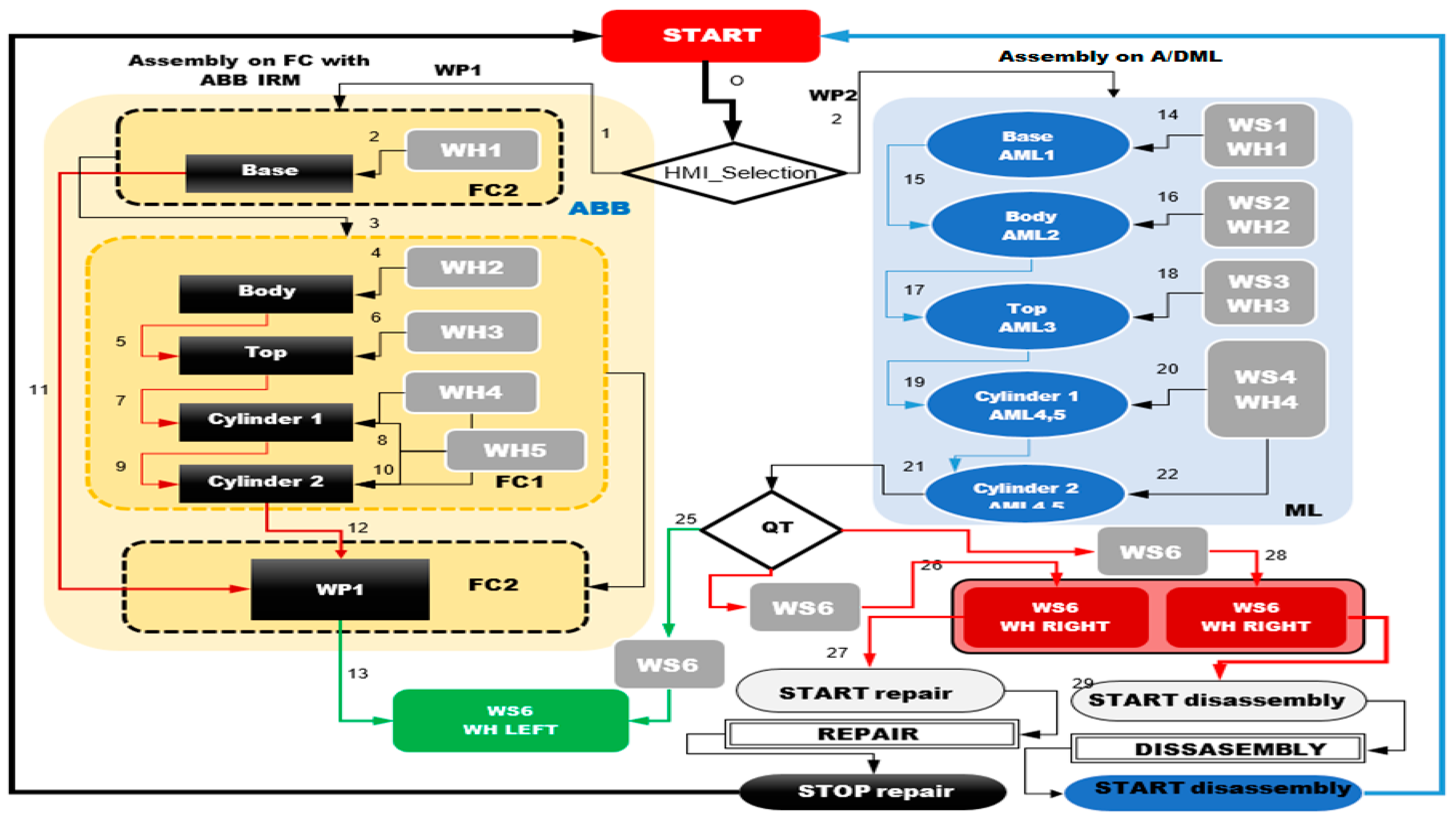
2. A/D/RML Assisted by CAS

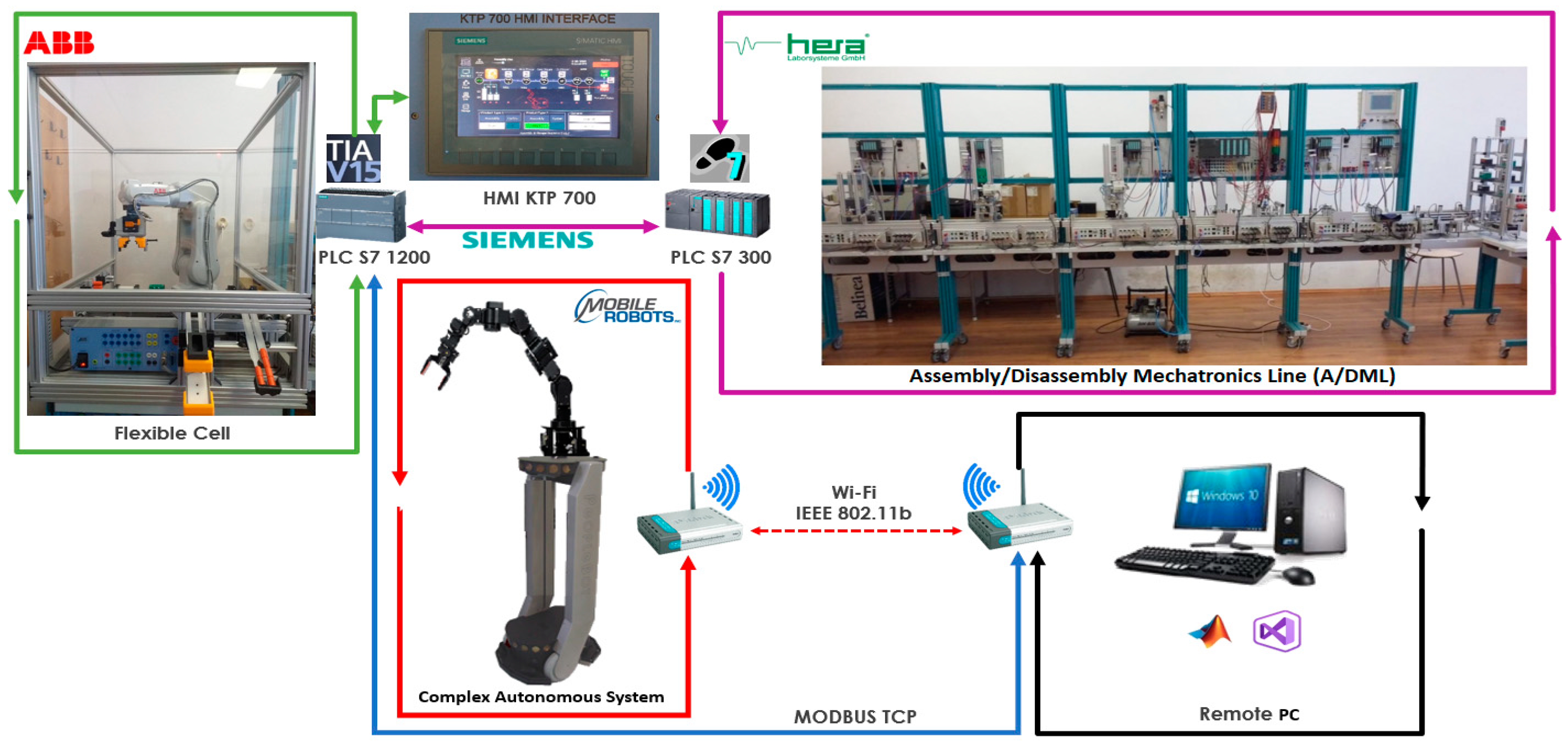
2.1. Hardware Architecture

The basic design concept consists of three main components/subsystems which are synchronized to work together and act as a flexible manufacturing line that performs several operations such as the assembly of two different products (workpieces) with disassembly, repair, and recover functionality.
The structure of the A/D/RML is shown in Figure 1. The major components are:
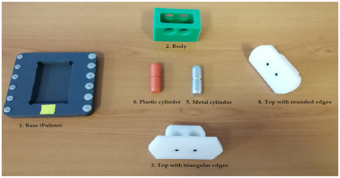
  • FC with 6-DOF ABB IRB120 IRM station used for assembly, disassembly, and repair of the workpieces with buffer, handling, processing, and transport capability;
  • A/DML 6-WS Hera&Horstmann ML based on laboratory mechatronic system, used for assembly and transport of the workpieces with checking and storage facility [10]. A/DML has some capabilities of disassembly but are not used in this paper;
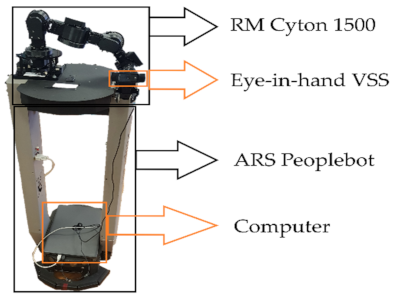
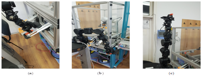
  • CAS PeopleBot WMR equipped with a 7-DOF Cyton 1500 RM used for recovery and transport/return operation of the dismantled workpart [13].
The A/D/RML, as described above, is characterized by a modular structure. The hardware structure consists of two PLCs controlled subsystems/modules with specific tasks for all the manufacturing stages.
  • FC Siemens S7-1200 PLC controls assembly/disassembly unit which handles the supply of workparts for the workpiece product type 1 and disassembly or repair for the workpiece type 2;
  • 6-WS Hera&Horstmann ML PLC (Siemens S7-300 series) has a predefined role as a logistics unit that assemblies individual workparts, transports between modules, and stores the assembled workpieces into the final storage place.
The PLC-based hardware and software structure, as seen in Figure 2, has hybrid architecture features of distributed and centralized/decentralized architecture.
  • Distributed structure, by means of separate PLCs for each of the two subsystems, to automate their respective areas with visualization or operation facilities.
  • Centralized/decentralized architecture, where the FC PLC (Siemens S7 1200) besides the local control role, acts as master PLC for centrally control both subsystems of the entire A/D/RML, process and operation facilities, thereby coordinating control tasks as well as synchronizing the operations of the CAS which include a running hardware multimedia interface (HMI) KTP 700 as the main visualization and operator control.
Each PLC, including Hera&Horstmann ML Siemens S7-300 PLC, hosts several control programs whose selection is made remotely, via an HMI or via the master PLC (Siemens S7-1200). The A/D tasks are controlled strictly through this master PLC, which acts as a Central System that handles visualization and operation of the complete A/D/RML. The Hera&Horstmann ML Siemens S7-300 PLC is connected to I/O points via Profibus (magenta line in Figure 1). Profibus topology is used to communicate and control the transporting conveyor belt drives, workpiece positioning, and synchronization methods as well as to handshake and signal interface exchange with the FC via the Profibus adapter. An additional HMI (Siemens TP 177) is connected for process visualization purposes only.
FC communication is based on the industrial Ethernet network Profinet technology (green line Figure 1), to communicate with the main HMI (Siemens KTP 700), ABB IRB120 IRM controller and Intelligent Siemens Servomotor Drives having their own positioning control functionality. Compatibility between FC and Hera&Horstmann ML, by means of communication is executed, as mentioned before, via a Profibus adapter to bridge (interconnect) the two different communication technologies: Profinet (protocol based on the Industrial Ethernet) and Profibus (protocol based on serial communication).
When disassembly or repairing action is performed in the FC (IRM disassembles or repairs the workpiece by replacing the bad components), the standby Cyton RM, part of the CAS system, will grab the recovered workparts to transfer them into the designated storage locations. Several synchronization signals are transferred between the master PLC and CAS, by means of Modbus TCP protocol, a standard communications protocol widely used in industrial automation. Some of these signals (e.g., acknowledge signals) are sent when FC accomplishes the repair/dismantle action, and the replaced component (workpart) is released and ready to be picked up by the CAS. Synchronization acknowledges signals will be returned, when CAS is busy during handling, picking up, transporting, or releasing a part. After that, CAS becomes available again.
Several algorithms have been developed using Siemens programming packages such as Totally Integrated Automation (TIA) Portal, Step7 Manager, as well as WinCC Flexible for the HMIs, for the inner loop of the developed strategy (PLC level). In both PLCs, modular programming is used, function blocks or functions are created as an entity, performing a particular functionality (Assembly, Disassembly, Transport, Storage) or controlling a particular type of device in the system (ABB Robot, conveyors motors, storage, electrical and pneumatic actuators). During each scan, the PLC reads all local and remote inputs, executes every function block and function in a predefined order (using IRQ), and updates all outputs at the end of each scan. An additional part of a PLC program is the communication between master PLC (FC S7-1200 PLC) and CAS via Modbus TCP link. For that, a Modbus TCP Server is configured and programmed in the Main Routine of the Siemens master PLC at the beginning of the scan prior to the program execution to establish and maintain a stable connection and quick data exchange-synchronization signals with the CAS.
As previously described, a separate Profibus communication link is used to interface data between PLCs (FC and A/DML). This data must be sent and received between master PLC and Siemens S7-300 PLC via Profibus communication adapter, as shown in Figure 2.

2.2. Flexible Cell with ABB IRM

FC is a laboratory integrated ABB IRB120 Robot Training Station, shown in Figure 3, which consists of the following major components:
  • 6-DOF ABB IRB120 IRM with electric gripper;
  • PLC Siemens S7-1200 series-CPU 1214C;
  • HMI Siemens KTP700, Colour Basic PN;
  • Switch Siemens SCALANCE XB005;
  • Conveyor Belt with Sinamics V90 Servo Drive;
  • Compact storage&unloading units corresponding to each of the five-part workpiece to be assembled.
Profinet communication link is used to interconnect and control all the above-mentioned devices of the FC. For the FC hardware structure, the following Profinet profiles are applicable:
  • Profinet-IO, Distributed I/O (Remote I/O), in which the user data from the field devices are periodically sent to the control system process model. This can be considered an evolved Profibus protocol on the TCP layer. Profinet-IO is used to link HMI, PLC CPU, and ABB IRM Controller;
  • PROFI drive, implemented for drives application scenarios and covers from simple frequency converters to intelligent servo drivers. This Profinet profile is used in Flexible Cell station to control the Conveyor Belt with Sinamics V90 Servo Drive.
ABB Robot Controller has the hardware capability to communicate with third party devices via Profinet protocol, as mention before. For that, a dedicated board AnybusCC Profinet slave (DSQC 688) is inserted into an expansion board on top of the main computer unit in the ABB Robot Controller. This Profinet Anybus device, DSQC 688, requires the Robot Controller DSQC1000 (main computer). With the Profinet Anybus Device option, the ABB IRM controller can act as a slave on the Profinet network.

2.3. A/DML Hera&Horstmann ML

The A/DML (Figure 4) includes six individual workstations with different tasks; each of them ensures the fulfilment of the operations for different stages: carrying and transporting, pneumatic workstations, conveyor belt, sorting unit, test station, and warehouse [6,10,11]. The five-part workpiece enables workflow operations such as assemblies, testing, sorting, storage, and disassembling. The components to be assembled are: workpart carrier (Base), Body, Top, Metal cylinder, and Plastic cylinder.

2.4. Hardware Structure of the CAS

The CAS, shown in Figure 5, is composed of the following elements: a 7-DOF Cyton 1500 RM equipped with an eye-in-hand type of VSS using a high-definition camera, both being connected to a computer via USB and synchronously communicating with the A/D/RML over Wi-Fi. The RM is placed on the ARS PeopleBot, which is a WMR with two driving wheels and one free wheel (2 DW/1 FW). The CAS is used to transport the recoverable pieces picked-up by the Cyton 1500 RM to the appropriate storage depots if the assembled piece has failed the quality test and has been disassembled or repaired.
The control of the CAS is carried out wirelessly using a router that is placed inside the WMR, through dedicated functions from ARIA (Advanced Robotic Interface for Applications) running on the same computer the Cyton RM is connected to.

2.5. Eye-In-Hand VSS

The eye-in-hand VSS is a system where the video sensor is placed on the last link of the RM, also known as the end-effector [13,17,24]. For this type of VSS, 2D image information is used to control the motion of the robot in the workspace. The object tracking and the robot positioning are achieved using the comparison between the current visual features, extracted from the images captured by the camera, and the desired visual features. The obtained difference is used to minimize the error between the present position of the piece and the anticipated location. Moreover, eye-in-hand type VSS indicates that the movement of the RM also induces motion of the mounted camera. One of the most utilized components in object detection and classification are called image moments. These image moments are commonly used in the robotics field because of their efficiency and simplicity in implementation. The image moments contain information about the region of interest, the coordinates of the gravity center of the piece, and the positioning of the image.

3. Flexibility and Multifunctionality of the A/D/R/ML

3.1. Flexibility

A/D/RML is a flexible manufacturing line because it assembles two different products, referred to as workpiece 1 (WP1) and workpiece 2 (WP2). WP1 is the workpiece with the Top part having triangular edges (Figure 6 and Figure 7a) and is assembled in the FC with the ABB IRM. WP2 is the workpiece with the Top part having round edges (Figure 7b,c) and is assembled on the Hera&Horstmann ML.

3.2. Multifunctionality

Assembly. The assembly of WP1 is made by the ABB IRM, taking from CF warehouses the components in order (Figure 7a: Base, Body, Top, and cylinders, Metal or Plastic. First, the Base is positioned on the conveyor belt (on FC2), then the rest of the product is assembled in a separate location of the FC (on FC1), then it is moved by the ABB IRM on the Base (on FC2). Finally, WP1 moves along the Hera&Horstmann ML and is stored on the left side of the WS6 station. The graphical user interface (GUI), on the HMI pen, allows selection for assembly between plastic cylinders and metal cylinders. Due to this fact, the WP1 product is of good quality and, for this reason, is stored in the rack on the left side of the WS6 station. The WP2 product is randomly assembled with the two cylinders and is subjected to the quality test on the WS4 station. To evaluate the quality for the WP2 product, the convention is that a WP2 product assembled with both metal cylinders is considered of good quality and is stored on the left side of the WS6 station. The WP2 product that contains both plastic cylinders (Figure 7b) is considered scrap product and it is stored in the rack on the right of the WS6 station. This WP2 will be disassembled for component recovery. The WP2 product having different material cylinders (Figure 7c) is also deposited in the rack on the right and it will be repaired by replacing the plastic cylinder with a metal one (Figure 8).
Disassembly. WP2 being considered scrap (it has two plastic cylinders, Figure 7b) is taken over by the elevator of the WS6 and positioned on the transport station WS5. It is transported along the Hera&Horstmann ML to the FC (FC2). The ABB IRM disassembles it in the established order: Cylinder 1 (left), Cylinder Two (right) Top, and Body (on FC1), letting them slide on the corresponding trough. The Base is transported back to WH1 located on ML, where the piston pushes it into the storage warehouse. CAS takes over each component in order, Cylinder 1, Cylinder 2, Body, and Top, transporting it to the appropriate storage warehouse on the Hera&Horstmann ML. The precision positioning of the CAS is performed with the eye-in-hand VSS (Figure 8).
Repair. WP2, having cylinders of different materials (Figure 7c), is taken over by the elevator of WP6 and positioned on WS5. It is transported along the Hera&Horstmann ML to the FC (FC2). The ABB IRM disassembles the plastic cylinder (on FC1), letting it slide on the exhaust chute and replaces it with a metal cylinder taken from the corresponding warehouse of the FC. CAS takes over the cylinder, in any position, 1 or 2, transporting it to the appropriate storage warehouse on the Hera&Horstmann ML. WP2, now having both metal cylinders, is a good quality product and it is transported from FC, along the Hera&Horstmann ML, to the WS6 station and stored on the left side (Figure 8).

3.3. Assumptions

Specialized technology on this type of A/D/RML represents the base of a multifunctional flexible industrial production line that gives a high range of standard products. Furthermore, by disassembly or repair, the products or parts can be recovered and brought to the quality standards. The technology on A/D/RML assisted by CAS and eye-in-hand VSS, developed below, depends on aspects such as operation modes, operation lengths, and types of finished products (Figure 8) [1,2,4,8]. Therefore, for FC, A/DML, CAS, and VSS some assumptions must be established for controlling whole system.
Assumption 1.
The A/D/RML is a single-model line, by the nature of the product, paced line (transfers between the workstations are synchronous), by the operation mode, and deterministic line, by the nature of operation times (times known certainly).
Assumption 2.
The number of the A/D/RML workstations involved in A/D/R is previously known and will remain unchanged (FC with ABB IRM and 6 workstations A/DML, Hera&Horstmann ML.
Assumption 3.
Two types of workpieces are assembled, WP1 in FC with ABB IRM, WP2 in Hera&Horstmann ML.
Assumption 4.
All conditions and parameters of the technology are initially known, including task durations.
Assumption 5.
The workstations of the A/D/RML have a linear distribution, FC and WS1 to WS6.
Assumption 6.
The assembly operations of WP1 are executed in FC. The assembly operations of WP2 are executed on Hera&Horstmann ML.
Assumption 7.
The left side (in green WH left) of the WS6 station is the warehouse where good products are stored, while the right side (in red WH right) is the warehouse where products that do not pass the quality test are stored, need to be disassembled or repaired.
Assumption 8.
The disassembly and repair operations of WP2 are executed on FC.
Assumption 9.
Disassembly and repair start after the WP2 is assembled and it fails the quality test.
Assumption 10.
WP2 which fails quality test is stored in the right side of WS6 and its disassembly or repair starts immediately after.
Assumption 11.
By convention, it is assumed that the WP2 fails the quality test if it contains either plastic cylinders or different materials.
Assumption 12.
One CAS assists the A/D/RML, having mounted a RM, used for picking up, transport and depot the workparts.
Assumption 13.
One eye-in-hand VSS camera is mounted on the RM.
Assumption 14.
CAS displacement is without obstacles and with the same constant speed.

3.4. Tasks Scheduling

Presented below are the block diagrams with the scheduling of tasks for each functionality, assembly in Figure 9, disassembly in Figure 10, and repair in Figure 11, respectively.

4. Industry 4.0 Based A/D/RML and CAS Communication, Control, and Synchronization

4.1. Communication and Control of A/D/RML

The A/DML (Hera&Horstmann ML) is controlled using a Siemens Simatic S7-300 Programmable Logic Controller (PLC), with five distributed modules connected by Profibus DP.
Profibus DP (Decentralized Periphery) is a RS-485 serial-based communication protocol, which ensures cyclic data exchange between PLCs (master) and devices (slaves). It polls slave distributed devices: master sending outputs and receiving inputs from all its devices, and then repeating the cycle.
Every remote I/O Workstation node and field IO device is grabbing info, writing or reading I/Os, device parameters, acting as a Profibus slave and sending response messages to the master PLC using bus cycle at regular intervals but also a cyclically on master device initiative (PLC controller).
Profibus complies with IEC 61158 and IEC 61784 standards and is oriented to the OSI (Open System Interconnection) reference model per international standard ISO 7498. Profibus is a deterministic protocol due to cyclic (periodic) polling mechanism between master and slaves. It uses transmission speeds from 9.6 kbps up to 12 Mbps.
The hardware structure of Hera&Horstmann ML (Figure 12) is based on a distributed architecture, integrating the process peripherals such as signals and function modules in Remote I/O stations on the Profibus link and consists of a Siemens Simatic S7-300 series PLC, processor type CP 314C-2 DP and Siemens CP 343-2 communication module for Profibus link. It uses Profibus DP interface, with defined speed of 12 Mbit/s and connects all six workstations Remote IOs (Siemens ET200S communication modules), which enhance flexibility and performance of flexible assembly/disassembly system within this decentralized architecture.
The main PLC rack consists of several analogue and digital IO cards, dedicated cards for counting and frequency measurement with 60 kHz, pulse width modulation with 2.5 kHz switching frequency as well as positioning cards with analogue output or digital outputs for the conveyor encoders used for precise motion control.
Each of the six Siemens ET200S Remote IO modules provide hardware-near signal, handling all the digital and analogue signals from transducers and to the actuators, as well as measuring and position detection for handling workpiece transportation and process through all line sections.
A Siemens HMI TP 177 operator touch panel is connected to the Profibus DP bus for presentation purposes only, allowing the operator to view the status of the mechatronics line and the current execution step of the assembly or disassembly process.
A communication adapter (Figure 12) Siemens CM 1242-5 attached to S7-1200 PLC is used for connecting the newer generation Siemens master PLC from FC, via Profibus link, to the A/DML.
This module is used to connect and integrate SIMATIC S7-1200 into an automation solution as a Profibus DP slave. The CM 1242-5 works as a DPV1 slave in accordance with IEC 61158, handles data traffic completely autonomously, and thus relieves the CPU of communication tasks.
Additionally, this communication module operates at two levels, i.e., physical layer and data link layer, converting and regenerating the signal it receives or sends and supports cyclic communication for the transfer of process data between Profibus DP slaves and DP master (Mechatronics Line S7-300 PLC). Cyclic communication is handled by the operating system of the CPU.

4.2. Moment-Based Image Method for VSS Modeling and Control

The structure of the eye-in-hand VSS contains the subsequent components: an autonomous system composed of a WMR equipped with a 7-DOF Cyton 1500 RM, a controller, and a visual sensor.
The most important part of this type of architecture, the image-based controller, needs deductive information about the environment of the system to minimize the error between the actual configuration of the visual features, f , and a desired configuration, f * . To model the open loop servoing system, the components of the fixed part must be analyzed individually; these components are the RM and the visual sensor.
The purpose of the eye-in-hand VSS is to minimize the error between the real and the desired features extracted by the video sensor [13,17,25].
The control structure of the VSS is shown in Figure 13. The signal associated to the input control of the CAS is υ c * , and represents the reference speed of the camera with the following structure: υ c * = υ * , ω * T , where υ * = υ x * , υ y * , υ z * T and ω * = ω x * , ω y * , ω z * T are defined as the linear and angular speed. The signal υ c * is expressed in the Cartesian space and requires a transformation to be applied to the RM.
The posture is defined by the integration of the reference speed of the camera, υ c * , and is noted with s = s 1 , s 2 , s 3 , s 4 , s 5 , s 6 T defining the robot Jacobian as follows:
J r = s i q j ,   i , j = 1 , , 6 ,
where q i , j = 1 , , 6 signifies the states of the RM’s joints. Consequently, the signal transformation of υ c * from Cartesian space to robotic joint space is J r 1 and the interaction matrix. The interaction matrix must fulfil a series of properties with the purpose of obtaining the ideal performance for a VSS, such as being non-singular and diagonal. The moments m i j are considered a set of visual features with the analytic form for the time variation, m ˙ i j , consequent to the moments of order i + j , differing depending on the speed of the camera υ c * according to the equation:
m ˙ i j = L m i j υ c ,
where L m i j = m υ x m υ y m υ z m ω x m ω y m ω z is the interaction matrix.
Based on the theory presented in [13,17,24], the interaction matrix corresponding to a set of image moments f = x n , y n , a n , τ , ξ , α T for n points is computed as follows:
L f = 1 0 0 a n e 11 a n 1 + e 12 y n 0 1 0 a n 1 + e 21 a n e 11 x n 0 0 1 e 31 e 32 0 0 0 0 τ ω x τ ω y 0 0 0 0 ξ ω x ξ ω y 0 0 0 0 α ω x α ω y 1 .

4.3. Control Input

The most common procedure to generate a control signal to the robots is the proportional control.
The eye-in-hand VSS can be interpreted as a minimization problem which calculates the path of the visual sensor using the minimum of the cost function attached to the error vector. The notations used are as follows: f * is the desired features vector, f is the current features vector, and r t is the relative position between the camera and the object at a specific time, t .
The features variation reported to the relative movement between the workspace and the video sensors is noted with f r t and its variation is described in the equation below:
f ˙ = f r d r d t + f t = L f υ c + f t .
For a static object, the time variation of the features reported to the motion is equal to zero, f t = 0 , and this implies that Equation (4) becomes:
f ˙ = L f υ c ,
where v c is the vector that depicts the relative speed between the object and the video sensor and L f is the interaction matrix from Relationship (3). To define the control law, it is mandatory to define an error function between the target features f * and the current features, f :
e = f f * .
Since most of implementations of VSS disregard the dynamics of the robot, equaling the dynamics to one, then υ c = υ c * and Equation (5) becomes:
f ˙ = L f υ c * .
From (6) and (7) the time variation of the error is expressed as:
e ˙ = L f υ c * ,
Because the robot control input is defined by υ c * and an exponentially negative minimization of error is expected, e ˙ = λ e ,   e ˙ = L f v c * = λ e , from the previous Equation (8) results in the control law below:
υ c * = λ L f + e ,
where L f   + is the pseudoinverse of the interaction matrix and is computed as the following:
L f + = L f T L f 1 .
Because in real-time eye-in-hand VSS, the Z distance between the points of interest and the reference system attached to the camera is not accurately known, L f + will be estimated, referred as L f + ^ .
The estimation of the matrix is based on the pseudo-inverse of the desired features interaction matrix L f + ^ = L f * + with L f + ^ = 1 2 L f + L f * + . Because the matrix remains constant during the control algorithm execution, the control law results as follows:
υ c * = 1 2 λ L f + L f * + e

4.4. Communication and Synchronisation

The remote PC computes control input and sends it to WMR. The remote PC also sends the data to the assembly line PLC (Figure 14) [10,12,19].
To control the CAS and the movement between the parking, grabbing, and placing positions, dedicated functions from ARIA programming package are used and the trajectory-tracking sliding-mode control (TTSMC) method is implemented.
As mentioned before, centralized architecture is used, where the FC PLC (Siemens S7 1200) acts as master PLC and synchronizes the operation with the CAS to perform the recovering process (recovering cylinders). Communication between master PLC (FC S7-1200 PLC) and CAS is executed via Modbus TCP Link.
In this application, remote PC is the Modbus master (on the Wireless TCP Network) and Siemens S7-1200 is the slave (Modbus Server considered in Siemens approach) (Figure 15 and Figure 16).
Depending on the task carried out by the A/D/RML, repair process (one cylinder released), or disassembly process (two cylinders released), two separate command signals are used for the interface master (from PLC S7 1200 to CAS):
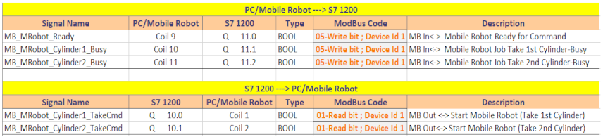
  • start Job CAS: Recover Process Cylinder 1;
  • start Job CAS: Recover Process Cylinder 2.
In the same way CAS, must acknowledge that the received command/action from A/D/RML line is handled; therefore three synchronization signals are used (from CAS to master PLC S7 1200):
  • CAS Ready for Command;
  • CAS Job started: Recover Process Cylinder 1;
  • CAS Job started: Recover Process Cylinder 2.
Although Modbus TCP is a deterministic protocol, the handling process commands between CAS and A/D/RML line are considered a critical control application, therefore a handshake exchange signal is applied to this communication interface—a synchronization between subsystems. In the first step, when a job command-task is sent to CAS for processing and recover a workpart, CAS must acknowledge when an action is performed. Second, when CAS finished processing a task or is in the Standby State, the Ready for Command signal is sent back to the master PLC.

5. Real-Time Control of the Repair Function

The states and duration of the transitions on A/D/RML to the real-time management related to the repair function, from the takeover of WP from WH right to its repaired storage in WH left, are shown in Figure 17, and Video S1.

5.1. CAS Control Loops

The mobile part of the A/D/RML, referred to as CAS, picks the pieces from the FC in the case of a repair or disassembly function and transports them to their proper storage warehouses (Figure 18, Figure 19 and Figure 20). The control of the mobile part is based on three control loops.
1.
Control loop for the synchronization between the Modbus PLC of the FC and the Cyton RM;
2.
Control loop of the Cyton RM with the eye-in-hand VSS for accurate positioning to pick up the objects from the FC and place them in the warehouses;
3.
Control loop of the PeopleBot WMR based on trajectory tracking sliding mode control (TTSMC) [19,31].
All three control loops communicate through one computer which contains the GUI and controls of the ARS, eye-in-hand VSS, and Cyton 1500 RM, and manages the synchronization with the FC.
Specific programming packages and libraries have been used with Microsoft Visual Studio to control the entire system. As it can be seen in the Figure 14, the communication between the Cyton RM, eye-in-hand VSS, and the computer is executed with USB connections, while the communication with FC is carried out wirelessly using a TCP/IP protocol [31].
The coordination between the control loops has been realized using the open-source library specialized in image processing, OpenCV, the control input defined in Equations (9) and (11), functions from Aria Mobile Robots, and synchronization with the FC’s Modbus PLC, all combined in Microsoft Visual Studio with the C++ programming language.
Figure 18 illustrates a series of images captured of RM Cyton located at the FC which show: (a) the home position, when all the joints have 0 radians value, (b) the intermediate position between the home and the scanning position, (c) the scanning position, where the eye-in-hand VSS is used for accurate localization of the object, (d) the error between the actual features extracted from the VSS and the desired features has been minimized, and (e) after the recoverable piece has been picked up by the RM. Figure 19 illustrates the images captured: (a) after the piece has been lifted by the gripper, (b) when the RM moves to the intermediary position with the recoverable object grasped, and (c) the trajectory to the parking position and starting the sequence of TTSMC for ARS PeopleBot. The reason for introducing the intermediate position is because the space between the FC and the RM Cyton is tight, so it is better and safer for it to move first to the right then descend, rather than just move down right to the scanning position.

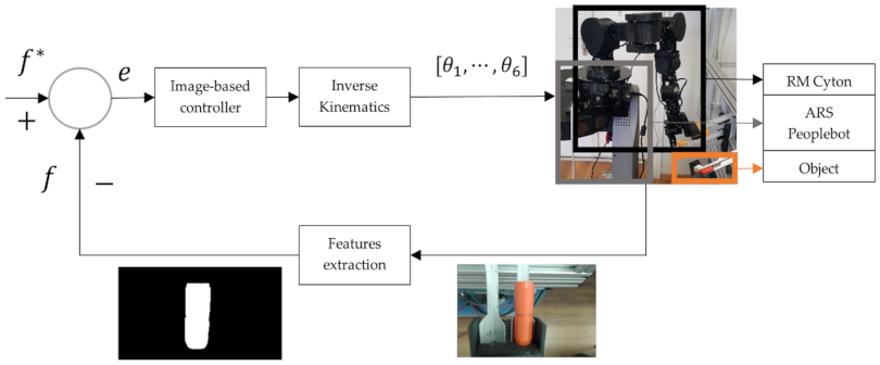
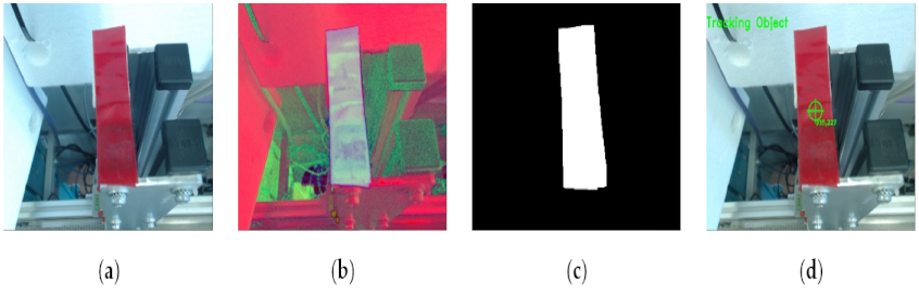
5.2. Object Detection, Image Processing and CAS Control for Repair Function

The main stages involved in object detection and tracking are shown in Figure 20. These stages are happening between steps (c) and (d) from Figure 18.
1.
The raw RGB (Red, Green, Blue) images are taken from the camera with a resolution of width 640 and of height 480; the camera has a fixed focus and white balance, so that it does not interfere with the colors;
2.
Conversion from BGR (Blue, Green, Red) is carried out in OpenCV to HSV (Hue, Saturation or Brightness);
3.
After the conversion, HSV limits are imposed, so that only the objects of a specific color between those limits can be detected. Morphological operations are additionally carried out at this step so that below elements are eroded while above elements are fixed so they can be seen more easily;
4.
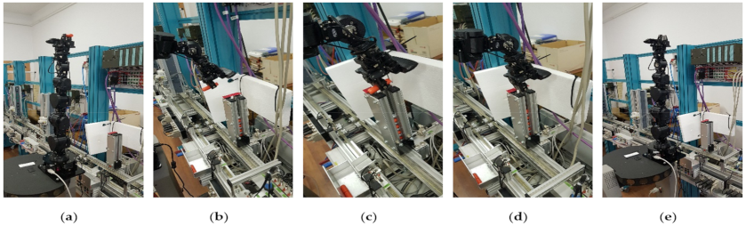
If a group of pixels has an aria in between the minimum and maximum values set in the program, then it will be considered an object and contour detection will start so that object detection becomes more precise. Finally, the centroid will be tracked using image moments method, shown in the image with the symbol. The RM Cyton will move based on the features tracked and once the error between the desired and real piece has been minimized enough, it will move above the piece and pick it up, then will turn to the intermediary position and finally the parking position.
If a group of pixels is below the minimum aria, then it will not be counted towards objects detected and if a group of pixels is larger than the maximum aria, the user is notified that the object detected is possibly eroded and will be considered noise.
Figure 21 shows some frames with the main steps performed by the RM Cyton at the warehouse where the object will be placed: (a) represents the RM with the object grasped in the gripper, (b) is the scanning position and positioning of the end-effector based on VSS, (c) shows that after the end-effector has been positioned, it moves above the warehouse, (d) is when the object is placed in the warehouse, (e) is when the RM returns to the home position. The steps illustrated in Figure 22 are happening between Figure 21b,c. Once the VSS sequence starts, (a) first it must take raw RGB images from the visual sensor, (b) convert them from BGR to HSV color space, so that in (c) segmentation of the desired color is executed more smoothly; finally, (d) after the operations are complete, the centroid will be detected and tracked with . The centroid will be used by the RM Cyton to position above the warehouse to place the object and then move back to the home position.
Figure 23 illustrates the desired and real trajectories of the ARS PeopleBot obtained with the TTSMC in closed loop control to move from the FC to the warehouse and back to the FC in the desired time. In (a) the complete route is presented, in (b) the X axis is separated, in (c) the Y axis is separated, and in (d) the angular trajectory is so that the differences between the real and desired trajectories can be perceived easier. There are two observable deviations, one after a 90 ° rotation is carried out to move forward to the warehouse, as shown in Figure 23c,d between 40 and 56 seconds on the X axis, and the second one again after a 90 ° rotation as to move back to the FC, shown in Figure 23c,d between 78 and 90 seconds on the X axis. The tracking errors are shown in Figure 24.
Figure 25a depicts the movement of the RM Cyton using inverse kinematics control (IKC) from the initial position to intermediary position for safety reasons, then to the scanning position with VSS so that the error between the actual and desired visual features is minimized, and finally, above the object, making a short movement to pick the object. Figure 25b–d represents the complete trajectory separated in x, y, and z, respectively, in absolute coordinates. The VSS sequence starts at second 28, this being the reason why the errors depicted in Figure 26 appear and it takes about 5 s for the error to be minimized (a) from 11 × 10−2 on the X axis, (b) from −13 × 10−3 on the Y axis, and (c) 10 s to be minimized from ± 4 × 10⁻².
Figure 27a presents the trajectory of the Cyton RM based on IKC from the parking position to scanning position with the eye-in-hand VSS, so that the end effector is exactly above the warehouse when placing the object. In the following Figure 27b–d, the trajectories are separated on the X, Y, and Z axes so that it is easier to see the exact trajectories on the individual axis.
Since the path of placing the object is performed after the ARS PeopleBot has moved from the FC to the warehouse, external factors (such as small deviations of the WMR trajectories) can influence the time necessary for the VSS to position the end-effector of the RM exactly above the deposit, since the hole it must be put in is exactly as wide as the object itself.
Compared to the errors in the Figure 26a–c, those presented in Figure 28 are smaller, but it takes a longer time to be minimized on the X and Y axis—about 25 s and with a precision of ± 2 × 10⁻⁴, as one can see in Figure 28a,b, compared to 5 s and a precision of 11 × 10−2 and −13 × 10−3 in Figure 26a,b, respectively. It is easy to see that it takes much less time to be positioned on the Z axis—2 s with a precision of 18 × 10−3, as shown in Figure 28c, compared to 10 s and an accuracy of ± 4 × 10⁻² as one can see in Figure 26c.

6. Discussion

Unlike [10], where we approached the problem of assembly/disassembly on the Hera&Horstmann mechatronics line served by an autonomous system consisting only of the mobile platform, on which is mounted a 5-DOF robotic manipulator, this paper proposes an extension both in hardware as well as software that allows the elaboration of a flexible and multifunctional technology, fully compatible with Industry 4.0, able to manufacture different products and to recover components or to repair products that do not correspond to the desired quality. All of these functionalities are made with high precision due to the integration of an industrial robotic manipulator, a complex autonomous system that is equipped with a mobile visual servoing system, and a communication structure between the flexible cell and the mechatronics line that allows synchronizations of operations and distributed control. The control structure is hierarchical with a supervisor that monitors the process, execution, and synchronization of tasks according to the strategy. The implementation of robust control architectures to uncertainties considered for all systems are the complex autonomous system, flexible cell, and mechatronics line. The uncertainties considered are faulty sensors/actuators, route/storage space blockage, and payload variation. Finally, the research is focused on developing a cyber-physical system, i.e., a multifunctional and flexible manufacturing system that integrates computational, networking, and physical components within a single functional environment.

7. Conclusions

The presented research is in progress, the final objective being the fully automated control, without the intervention of a human operator, of the multifunctional technology of flexible manufacturing for a given production volume, with recovery, reuse of subassemblies, and repair of inadequate quality WPs. The research is aimed at dual purposes, one educational and another as close as possible to the real world. The educational goal aims to familiarize the system designer with everything that defines Industry 4.0 and the cyber-physical system. The educational goal is achieved by addressing the following topics: SCADA systems, communication and synchronization of tasks based on signals from sensors and actuators, PLC programming, precise positioning by visual servoing systems, control of mechatronics lines, mobile robots, and robotic manipulators. All of these bring the technology closer to the concepts and attributes of Industry 4.0. Regarding correspondence with the real industrial world, most manufacturing lines are assisted by robotic systems that have a fixed position. Through this study, we extended the degree of automation and efficiency of these production lines using mobile robotic systems equipped with manipulators and visual servoing systems. Thus, the manufacturing lines become multifunctional, able to recover and reuse components and subassemblies, if the final product does not meet quality requirements. Although this technology is implemented on a laboratory system, it can still be applied in sorting, dosing, sealing, and packaging operations in the industries of pharmaceutics, food, and consumer goods. We mention the following as being exclusively the contributions of the authors: hardware design, configuration, ABB IRM and PLC programming, and graphical interface of the FC; hardware configuration and PLC programming of the Hera&Horstmann ML; coupling and compatibility between CF, Hera&Horstmann ML and CAS; CAS hardware configuration and control; formulating the set of assumptions so that the entire system corresponds to the requirements of the multifunctional technology of flexible manufacturing; and real-time control of the entire system.

Supplementary Materials

The following are available online at www.cidsacteh.ugal.ro/video/Video_PPB_Cyton.mp4, Video S1: Multifunctional Flexible Manufacturing Technology on a Mechatronics Line with Integrated Industrial Robotic Manipulator Assisted by a Complex Autonomous System, repair function (cylinder replacement).

Author Contributions

Conceptualization, A.F. (Adriana Filipescu), D.I., A.F. (Adrian Filipescu), E.M. and G.S.; methodology, A.F. (Adriana Filipescu), A.F. (Adrian Filipescu), E.M. and D.I.; software, D.I., G.S.; validation, A.F. (Adrian Filipescu) and E.M.; formal analysis, D.I. and G.S.; writing—original draft preparation, A.F. (Adriana Filipescu) and A.F. (Adrian Filipescu); writing—review and editing, A.F. (Adriana Filipescu) and A.F. (Adrian Filipescu); supervision, A.F. (Adrian Filipescu); project administration, A.F. (Adrian Filipescu); funding acquisition, A.F. (Adrian Filipescu) and D.I. All authors have read and agreed to the published version of the manuscript.

Funding

This research was funded by the Romanian Executive Unit of Funding Higher Education, Research, Development, and Innovation (UEFISCDI), project number: PN-III-P1-1.2-PCCDI-2017-0290, project title: Intelligent and distributed control of 3 complex autonomous systems integrated into emerging technologies for medical-social personal assistance and servicing of precision flexible manufacturing lines.

Institutional Review Board Statement

Not applicable.

Informed Consent Statement

Not applicable.

Acknowledgments

This article (APC) will be supported by Doctoral School of Fundamental Sciences and Engineering, “Dunărea de Jos” University of Galati.

Conflicts of Interest

The authors declare no conflict of interest.

References

  1. Chryssolouris, G. Manufacturing Systems—Theory and Practice; Springer: New York, NY, USA, 2005. [Google Scholar]
  2. Filipescu, A. Contributions to Electric Drive of the Flexible Manufacturing Lines and Integrated Robots. Ph.D. Thesis, University of Galati, Galati, Romania, 2017. [Google Scholar]
  3. Carlos-Mancilla, M.A.; Luque-Vega, L.F.; Guerrero-Osuna, H.A.; Ornelas-Vargas, G.; Aguilar-Molina, Y.; González-Jiménez, L.E. Educational Mechatronics and Internet of Things: A Case Study on Dynamic Systems Using MEIoT Weather Station. Sensors 2021, 21, 181. [Google Scholar] [CrossRef] [PubMed]
  4. Florescu, A.; Barabas, S.A. Modeling and Simulation of a Flexible Manufacturing System—A Basic Component of Industry 4.0. Appl. Sci. 2020, 10, 8300. [Google Scholar] [CrossRef]
  5. Berriche, A.; Mhenni, F.; Mlika, A.; Choley, J.-Y. Towards Model Synchronization for Consistency Management of Mechatronic Systems. Appl. Sci. 2020, 10, 3577. [Google Scholar] [CrossRef]
  6. Radaschin, A.; Voda, A.; Minca, E.; Filipescu, A. Task Planning Algorithm in Hybrid Assembly/Disassembly Process. In Proceedings of the 14th IFAC Symposium on Information Control Problems in Manufacturing, Bucharest, Romania, 23–25 May 2012. [Google Scholar]
  7. Kallrath, J. Planning and scheduling in the process industry. In Advance Planning and Scheduling Solution in Process Industry; Springer: Berlin/Heidelberg, Germany, 2003; pp. 201–227. [Google Scholar]
  8. Tolio, T. Design of Flexible Production Systems—Methodologies and Tools; Springer: Berlin/Heidelberg, Germany, 2009. [Google Scholar]
  9. Peters, A.A.; Vargas, F.J.; Garrido, C.; Andrade, C.; Villenas, F. PL-TOON: A Low-Cost Experimental Platform for Teaching and Research on Decentralized Cooperative Control. Sensors 2021, 21, 2072. [Google Scholar] [CrossRef] [PubMed]
  10. Minca, E.; Filipescu, A.; Voda, A. Modelling and control of an assembly/disassembly mechatronics line served by mobile robot with manipulator. Control Eng. Pract. 2014, 31, 50–62. [Google Scholar] [CrossRef]
  11. Filipescu, A.; Filipescu, A., Jr. Simulated Hybrid Model of an Autonomous Robotic System Integrated into Assembly/Disassembly Mechatronics Line. IFAC Proc. Vol. 2014, 47, 9223–9228. [Google Scholar] [CrossRef] [Green Version]
  12. Dragomir, F.; Mincă, E.; Dragomir, O.E.; Filipescu, A. Modelling and Control of Mechatronics Lines Served by Complex Autonomous Systems. Sensors 2019, 19, 3266. [Google Scholar] [CrossRef] [PubMed] [Green Version]
  13. Filipescu, A.; Mincă, E.; Filipescu, A.; Coandă, H.-G. Manufacturing Technology on a Mechatronics Line Assisted by Autonomous Robotic Systems, Robotic Manipulators and Visual Servoing Systems. Actuators 2020, 9, 127. [Google Scholar] [CrossRef]
  14. Stoll, J.T.; Schanz, K.; Pott, A. Mechatronic Control System for a Compliant and Precise Pneumatic Rotary Drive Unit. Actuators 2020, 9, 1. [Google Scholar] [CrossRef] [Green Version]
  15. He, Y.; Stecke, K.E.; Smith, M.L. Robot and machine scheduling with state-dependent part input sequencing in flexible manufacturing systems. Int. J. Prod. Res. 2016, 54, 6736–6746. [Google Scholar] [CrossRef]
  16. Guiras, Z.; Turki, S.; Rezg, N.; Dolgui, A. Optimization of Two-Level Disassembly/Remanufacturing/Assembly System with an Integrated Maintenance Strategy. Appl. Sci. 2018, 8, 666. [Google Scholar] [CrossRef] [Green Version]
  17. Filipescu, A.; Minca, E. Mechatronics Manufacturing Line with Integrated Autonomous Robots and Visual Servoing Systems. In Proceedings of the 9th IEEE International Conference on Cybernetics and Intelligent Systems, and Robotics, Automation and Mechatronics (CIS-RAM 2019), Bangkok, Thailand, 18–20 November 2019; pp. 620–625. [Google Scholar]
  18. Minca, E.; Filipescu, A.; Coanda, H.G.; Dragomir, F.; Dragomir, O.E.; Filipescu, A. Extended Approach for Modeling and Simulation of Mechatronics Lines Served by Collaborative Mobile Robots. In Proceedings of the 22nd International Conference on System Theory, Control and Computing (ICSTCC), Sinaia, Romania, 10–12 October 2018; pp. 335–341. [Google Scholar]
  19. Ciubucciu, G.; Filipescu, A.; Filipescu, A., Jr.; Filipescu, S.; Dumitrascu, B. Control and Obstacle Avoidance of a WMR Based on Sliding-Mode, Ultrasounds and Laser. In Proceedings of the 12th IEEE International Conference on Control and Automation (ICCA), Kathmandu, Nepal; 1–3 June 2016; pp. 779–784. [Google Scholar]
  20. Gasparetto, A.; Zanotto, V. A new method for smooth trajectory planning of robot manipulators. Mech. Mach. Theory 2007, 42, 455–471. [Google Scholar] [CrossRef]
  21. Barczak, A.; Dembińska, I.; Marzantowicz, Ł. Analysis of the Risk Impact of Implementing Digital Innovations for Logistics Management. Processes 2019, 7, 815. [Google Scholar] [CrossRef] [Green Version]
  22. Fan, Y.; Lv, X.; Lin, J.; Ma, J.; Zhang, G.; Zhang, L. Autonomous Operation Method of Multi-DOF Robotic Arm Based on Binocular Vision. Appl. Sci. 2019, 9, 5294. [Google Scholar] [CrossRef] [Green Version]
  23. Ravankar, A.; Ravankar, A.A.; Kobayashi, Y.; Hoshino, Y.; Peng, C.-C. Path Smoothing Techniques in Robot Navigation: State-of-the-Art, Current and Future Challenges. Sensors 2018, 18, 3170. [Google Scholar] [CrossRef] [PubMed] [Green Version]
  24. Copot, C. Control Techniques for Visual Servoing Systems. Ph.D. Thesis, Technical University of Iasi, Iasi, Romania, 2012. [Google Scholar]
  25. Petrea, G.; Filipescu, A.; Solea, R.; Filipescu, A., Jr. Visual Servoing Systems Based Control of Complex Autonomous Systems Serving a P/RML. In Proceedings of the 22nd IEEE, International Conference on System Theory, Control and Computing, (ICSTCC). Sinaia, Romania, 10–12 October 2018; pp. 323–328. [Google Scholar]
  26. Song, R.; Li, F.; Fu, T.; Zhao, J. A Robotic Automatic Assembly System Based on Vision. Appl. Sci. 2020, 10, 1157. [Google Scholar] [CrossRef] [Green Version]
  27. Lan, C.-W.; Chang, C.-Y. Development of a Low Cost and Path-free Autonomous Patrol System Based on Stereo Vision System and Checking Flags. Appl. Sci. 2020, 10, 974. [Google Scholar] [CrossRef] [Green Version]
  28. Deng, L.; Wilson, W.; Janabi-Sharifi, F. Dynamic performance of the position-based visual servoing method in the cartesian and image spaces. In Proceedings of the IEEE/RSJ International Conference on Intelligent Robots and Systems, Las Vegas, NV, USA, 27–31 October 2003; pp. 510–515. [Google Scholar]
  29. Gans, N.; Hutchinson, S.; Corke, P. Performance tests for visual servo control systems, with application to partitioned approaches to visual servo control. Int. J. Robot. Res. 2003, 22, 955–981. [Google Scholar] [CrossRef]
  30. Corke, P.I.; Spindler, F.; Chaumette, F. Combining Cartesian and polar coordinates in IBVS. In Proceedings of the 2009 IEEE/RSJ International Conference on Intelligent Robots and Systems, St. Louis, MO, USA, 11 December 2009; pp. 5962–5967. [Google Scholar]
  31. Tatipala, S.; Wall, J.; Johansson, C.; Larsson, T. A Hybrid Data-Based and Model-Based Approach to Process Monitoring and Control in Sheet Metal Forming. Processes 2020, 8, 89. [Google Scholar] [CrossRef] [Green Version]
Figure 1. Control structure of A/DML Hera&Horstmann, FC with ABB IRM and CAS with PeopleBot WMR and Cyton 1500 RM.
Processes 09 00864 g001
Figure 2. Flexible Cell Siemens S7-1200 PLC hardware structure.
Processes 09 00864 g002
Figure 3. Flexible Cell Station with 6-DOF ABB IRB120.
Processes 09 00864 g003
Figure 4. A/DML Hera&Horstmann ML with symmetrical final product storage.
Processes 09 00864 g004
Figure 5. The CAS composed of ARS, RM, eye-in-hand VSS, and a computer.
Processes 09 00864 g005
Figure 6. Workpiece parts.
Processes 09 00864 g006
Figure 7. Assembled workpieces: (a) workpiece with metal cylinders; (b) workpiece with plastic cylinders; (c) workpiece with different material cylinders.
Processes 09 00864 g007
Figure 8. A/D/RML assisted by CAS.
Processes 09 00864 g008
Figure 9. Task scheduling for assembly functionality.
Processes 09 00864 g009
Figure 10. Task scheduling for disassembly functionality.
Processes 09 00864 g010
Figure 11. Task scheduling for repair functionality.
Processes 09 00864 g011
Figure 12. PLC hardware structure of the Mechatronics line Hera&Horstmann.
Processes 09 00864 g012
Figure 13. Closed-loop control of the RM Cyton based on eye-in-hand type VSS.
Processes 09 00864 g013
Figure 14. Communication block set of the computer between the FC, ARS PeopleBot WMR equipped with the Cyton RM and eye-in-hand VSS.
Processes 09 00864 g014
Figure 15. Modbus message interface (Modbus Map).
Processes 09 00864 g015
Figure 16. Siemens Modbus Server configuration in main routine.
Processes 09 00864 g016
Figure 17. A/D/RML state transitions of repair function.
Processes 09 00864 g017
Figure 18. Real-time control of the 7-DOF Cyton 1500 RM located at the FC with the following sequences: (a) home position, (b) intermediary position, (c,d) scanning position, (e) picking object.
Processes 09 00864 g018
Figure 19. Real-time control of the RM Cyton 7-DOF located at the FC with the following sequences: (a) lifting object, (b) moving to the intermediate position, (c) parking position with the piece in the gripper.
Processes 09 00864 g019
Figure 20. Object Detection with the following steps: (a) raw RGB image taken from the camera, (b) conversion from BGR to HSV (c) image segmentation after HSV limits are set, with morphological operations of erosion and dilation, (d) object is detected and the centroid is being tracked.
Processes 09 00864 g020
Figure 21. Real-time control of the RM Cyton located at the cylinders warehouse which has the resulting actions: (a) parking position with the object in the gripper, (b) scanning position, (c) moving above the warehouse, (d) placing the piece in the depot, (e) returning to home position.
Processes 09 00864 g021
Figure 22. Warehouse reference color detection: (a) raw RGB image, (b) BGR to HSV conversion, (c) HSV limits are imposed and the result is shown as a white blob with a black background, (d) the reference color is detected, and the centroid is tracked.
Processes 09 00864 g022
Figure 23. Desired and real trajectories of ARS PeopleBot based on Trajectory Tracking Sliding Mode Control: (a) complete trajectory, (b) X axis, (c) Y axis, and (d) angular trajectories.
Processes 09 00864 g023
Figure 24. (a) X axis and (b) Y axis tracking errors in absolute coordinates, (c) angular tracking error expressed in radians per second for ARS PeopleBot.
Processes 09 00864 g024
Figure 25. Desired and real object picking trajectories of the RM Cyton based on inverse kinematics control and eye-in-hand VSS for accurate positioning at the FC: (a) the complete trajectory, from the home position to above object position, (b) X axis, (c) Y axis, (d) Z axis trajectories.
Processes 09 00864 g025
Figure 26. Tracking errors for RM Cyton picking object trajectory on: (a) X axis, (b), Y axis, (c) Z axis.
Processes 09 00864 g026
Figure 27. Desired and real object placing trajectories of the RM Cyton based on inverse kinematics control and eye-in-hand VSS for positioning at the warehouse: (a) signifies the complete trajectory, while (bd) are the trajectories separated on the X, Y, and Z axes, respectively.
Processes 09 00864 g027
Figure 28. Tracking errors for RM Cyton placing object trajectory on: (a) X axis, (b) Y axis, and (c) Z axis.
Processes 09 00864 g028
Publisher’s Note: MDPI stays neutral with regard to jurisdictional claims in published maps and institutional affiliations.

