Article

Electrodeposited PPy@TiO2 and PEDOT@TiO2 Counter Electrodes for [Co(bpy)3]2+/3+ Redox Mediator-Based Dye-Sensitized Solar Cells

1
Chemistry Department, Faculty of Science, Al-Azhar University, Assiut 71524, Egypt
2
State Key Laboratory of Silicate Materials for Architecture, Wuhan University of Technology, Luoshi Road, Wuhan 430070, China
3
Key Laboratory for Applied Surface and Colloid Chemistry, Ministry of Education, Shaanxi Key Laboratory for Advanced Energy Devices, Shaanxi Engineering Lab for Advanced Energy Technology, School of Materials Science & Engineering, Shaanxi Normal University, Xi’an 710119, China
*
Authors to whom correspondence should be addressed.
Inorganics 2022, 10(11), 213; https://doi.org/10.3390/inorganics10110213
Submission received: 20 October 2022 / Revised: 12 November 2022 / Accepted: 14 November 2022 / Published: 18 November 2022
(This article belongs to the Collection Coordination Complexes for Dye-Sensitized Solar Cells (DSCs))

Abstract

:
The main goal of this work is to enhance the catalytic performance of PPy and PEDOT films toward the Co2+/Co3+ redox couple. PPy and PEDOT films were electrodeposited separately on a porous TiO2 template to assess their suitability as alternative catalysts in dye-sensitized solar cells (DSSC) based on the [Co(bpy)3]2+/3+ redox shuttle. The obtained PPy@TiO2 and PEDOT@TiO2 counter electrodes displayed much rougher surfaces. Electrochemical studies indicate the superior catalytic activity of both the electrodeposited electrodes toward Co3+ reduction, as indicated by lower charge transfer resistance than that of pristine films and even that of Pt electrodes. Therefore, the fabricated DSSC devices with these counter electrodes achieved higher power conversion efficiencies compared to cells with pristine PPy and PEDOT counter electrodes, or even with a Pt counter electrode. Interestingly, the assembled DSSC device with a PEDOT@TiO2 counter electrode displayed the highest performance among all with a power conversion efficiency of 6.62%, which is better than that obtained by the device with a Pt electrode (6.07%).

1. Introduction

Environmental pollution and climate change are the most prominent threats facing humanity in recent times due to the imposing and increasing use of fossil and non-renewable energy sources, so the search for safe and environmentally friendly alternative energy sources has become an urgent matter, not a luxury. In the last decades, solar energy has received great attention as one of the most encouraging sustainable energy sources for future generations due to its availability worldwide [1]. Solar cells or photovoltaics (PV) are a promising technique used to make use of solar energy by converting it to electrical energy via the photovoltaic effect [2]. Until now, various kinds of solar cells have been developed with considerable power conversion efficiency; however, the high production costs and low abundance of toxic metals restrict their wide installation. Thus, intensive efforts have been made to develop cheaper and more eco-friendly solar cells.
Since 1991, dye-sensitized solar cells (DSSCs) have attracted remarkable attention as a promising alternative to traditional silicon-based solar cells [3,4]. This is due to their simple fabrication with low-cost materials, relatively high power conversion efficiency, effective response to diffused light, and compatibility with building window glass or on a flexible substrate [4]. Due to continuous development, the conversion efficiency of the DSSCs recently exceeds 13% under full sun illumination (AM 1.5G) [5,6]. Typically, a DSSC device is composed of a photoanode to absorb the incident sunlight, an electrolyte with a redox mediator as the inner transport medium to provide ionic conductivity, and a counter electrode (CE). The CE is the part responsible for collecting the electron from the external circuit to catalyze the reduction of the oxidized species of the redox couple; the reduced form of the redox couple will diffuse to the anode and hence regenerate the oxidized form of the dye to its ground state via photo-injection of the electrons into the porous TiO2 film. Therefore, the CE should display a lower charge transfer electron at the CE/electrolyte interface to promote the full process. The full structure of a DSSC device and the work function process are shown in Figure 1 [7,8,9].
Conventionally, I 3 / I is the most common redox system for DSSCs with high performance [10,11,12]. However, the I 3 / I redox system has some limitations, including a relatively low redox potential (0.35 V), a low open circuit voltage (VOC), and a short circuit current density (JSC), as well as a corrosive nature toward metallic grids. Moreover, the I 3 / I redox shuttle shows partial absorption in visible light (λ ~300–430 nm) due to the presence of the triiodide ( I 3 ) species [13]. Therefore, various alternative redox couples such as nickel(III/IV) [14], copper(I/II) [15], disulfide/thiolate (T2/T) [16], ferrocene/ferrocenium (Fc/Fc+) [17], and Co2+/Co3+ [18] have been developed in order to overcome these limitations. Cobalt-based complexes have received great attention as promising alternative redox couples, this is due to various advantages such as non-corrosive toward metallic cathodes, non-volatility, lightly colored and tunable redox potentials by modification of the attached ligands [18,19,20,21,22,23]. Recently, Co(II/III)-polypyridyl complexes ([Co(bpy)3]2+/3+; bpy = 2, 2′-bipyridine) have attracted intensive interest as a redox couple in DSSCs with higher power conversion efficiency (PCE). For example, Yella et al. reported that the assembled devices in conjunction with the [Co(bpy)3]2+/3+ redox couple and donor-π-bridge-acceptor porphyrin sensitizer (YD2-o-C8) showed PCE of 12.3% [24]. Further enhancement was achieved by the incorporation of a proquinoidal benzothiadiazole (BTD) into the porphyrin structure. The DSSC demonstrated a PCE of 13% [5]. However, the Co2+/Co3+ complex system is a one-electron transfer that displays fast recombination of electrons from the CB of the TiO2 [25]. In addition, the larger molecular size of the Co2+/Co3+ complexes limits their mass diffusion in the electrolyte solution and the porous semiconductor [26,27]. Typically, organic dyes with high extinction coefficients allow using thinner TiO2 films, as well as highly catalytic CEs to quickly reduce Co3+ to Co2+ to overcome the diffusion issue and decrease the recombination reaction rate to achieve high conversion efficiency [27,28].
Although Pt-CE is the most widely used catalytic material for the I 3 / I redox system with high catalytic performance, the high cost, corrosion ability in the presence of the iodide-based electrolyte, and the high temperature needed for preparing the Pt CE are the main challenges that need to be solved. Thus, various catalytic materials have been developed and utilized as alternative CEs without sacrificing catalytic activity. For example, Zhang et al. [29] significantly enhanced the catalytic performance of Kesterite Cu2ZnSnS4 (CZTS) toward I 3 reduction via the element substitution of Zn2+ by Co2+ and Ni2+ cations. The assembled DSSC with modified CZTS showed a PCE of 8.3%, which is comparable with that achieved with the Pt CE. Furthermore, binary metal sulfides (CuxCoySz) displayed a potential ability as an alternative CE for DSSCs with the I 3 / I redox couple, as indicated by a higher PCE (8.60%), which is better than that achieved with Pt-CE (7.75%) [25]. Metal selenides also showed potential catalytic activity as reported by Ho et al., in which a hierarchical urchin-like structure of CoSe2/CoSeO3 was synthesized via the one-step hydrothermal method [30]. The electrochemical analysis showed that the PCE of the related assembled DSSCs is 9.29%, which is better than that of the cell with Pt CE (8.33%). Furthermore, under 2.21 mW cm2 light intensity, the devices with the CoSe2/CoSeO3 CE had a PCE of 19.88%. This indicates that CoSe2/CoSeO3 CE is a promising alternative CE for DSSCs under outdoor and indoor conditions. Carbon-based materials also showed outstanding catalytic performance toward the I 3 / I redox couple. For example, Pang et al. reported that the nitrogen-doped carbon nano-onions with modified reduced graphene (N-CNOs/mGr) composite displayed higher and excellent catalytic activity toward I 3 reduction, and even better than that achieved with the standard Pt CE. The PCE of the related liquid state DSSC with N-CNOs/mGr was 10.28%, which is much higher than that of the Pt CE (6.54%) [31]. In the last few years, our group utilized carbon-based materials such as NiO@C-derived from walnut shell [32], carbon black-Si3N4 [33], and carbon black-SiO2 as alternative CEs with promising catalytic performances [34]. However, For the monoelectronic redox couples based on coordination compounds such as the Co 2 + / Co 3 + system, Pt is not the best catalytic material [35]. For example, Kavan et al. reported that the electrocatalytic performance of the graphene nanoplatelets (GNP) coated on fluorine-doped SnO2 (FTO) is higher than that achieved with the Pt CE. The PCE of the assembled DSSCs with GNP is superior to that with the Pt CE under the same working conditions [36]. Furthermore, Ju et al. [37], reported that the DSSC with electrospray nitrogen-doped graphene nanoplatelets (NGnP) CE showed a PCE of 9.05%, which is superior to that with the Pt CE (8.43%). According to Lee et al., carbon black (CB) demonstrated promising catalytic performance toward the [Co(bpy)3]2+/3+ redox mediator [38]. The assembled DSSCs exhibited a PCE of 8.81%, which is much better than that of the Pt CE (7.10%). Recently, Han et al. [39], prepared Cu2−xSe@N-doped carbon nanosheets as transparent CE by using a Cu-TCPP metal-organic framework thin film as a template in the presence of selenium powder under a nitrogen atmosphere. The bifacial DSSCs fabricated achieved a PCE of 7.61% and 5.82% from the front and rear irradiation, respectively, which is comparable to that with Pt CE.
Conducting polymers often outperformed Pt CEs in electrocatalytic activities toward the [Co(bpy)3]2+/3+ redox couple. The most efficient PEDOT-based CEs are prepared by electrodeposition methods [40]. For instance, Bignozzi et al. demonstrated that electrodeposited poly (3,4-ethylenedioxythiophene) (PEDOT) CE has distinct electrocatalytic activity toward [Co(bpy)3]2+/3+ redox mediators, and the total performance of the assembled DSSCs is competitive with that for Au and Pt CEs [28]. Doping is an efficient technique for enhancing the catalytic performance of the PEDOT-based CEs. For example, Boschloo et al. revealed that the electrocatalytic performance of the PEDOT doped with iron (III) tris-p-toluenesulfonate (PEDOT: Tos) toward the [Co(bpy)3]2+/3+ redox shuttle exceeded that of the Pt CE. The DSSCs with PEDOT: Tos CE yielded a PCE of 6.3%, higher than with the Pt CE (6.1%) [41]. Utilizing sodium dodecyl sulfate (SDS) or LiClO4 are the famous dopants for PEDOT, in which the SDS is performed in water solution and the latter in organic media. SDS in water is preferred due to the non-flammability, low cost and abundance of water. In addition, it is more suitable for large-scale production. Most recently, Carli et al. [35], reported that the electrocatalytic activity of the electrodeposited PEDOT/Nafion toward a Co2+/Co3+-based redox mediator was comparable to that of PEDOT/ClO4 and significantly superior to that of PEDOT/PSS. The electrodeposited doped PEDOT showed superior catalytic activity toward the Co2+/Co3+-based redox mediators. However, the total performance still needs extensive work to be suitable for market production.
Poly pyrrole (PPy) is another conducting polymer that has attracted intensive attention as a promising alternative CE due to its high conductivity, low cost, as well as considerable electrocatalytic activity for I 3 reduction. Although several studies have reported the successful use of PPy as a CE for redox-based DSSCs [40,41,42], its applications in Cobalt-based devices are still uncommon. Although the promising performance of both PEDOT and PPy as alternative CEs toward the Co2+/Co3+-based redox mediators, the smooth surface morphology is a challenge, which sacrifices the performance of the assembled DSSC devices. Inserting a 3D porous template between the substrate and the electrodeposited film showed a promising strategy for enhancing the electrocatalytic performance. For example, Cheng et al. reported that inserting TiC or TiN nanoparticles as 3D porous templates remarkably enhanced the catalytic performance of the electrodeposited PEDOT toward the Co2+/Co3+-polypyridyl redox mediator compared with pristine PEDOT CE or even with Pt CE [27]. In this work, a screen-printed TiO2 film was utilized as a porous template for the electrodeposited PPy, and PEDOT layers. The morphology and electrochemical properties of PEDOT@TiO2 and PPy@TiO2 CEs, as well as their use as Pt-free catalysts for the [Co(bpy)3]2+/3+ redox couple, are discussed. To the best of our knowledge, this is the first time such CEs have been used for DSSCs based on a Co2+/Co3+ mediator. This has revealed the potential ability to utilize PEDOT@TiO2 and PPy@TiO2 as alternative CEs in DSSCs.

2. Results and Discussion

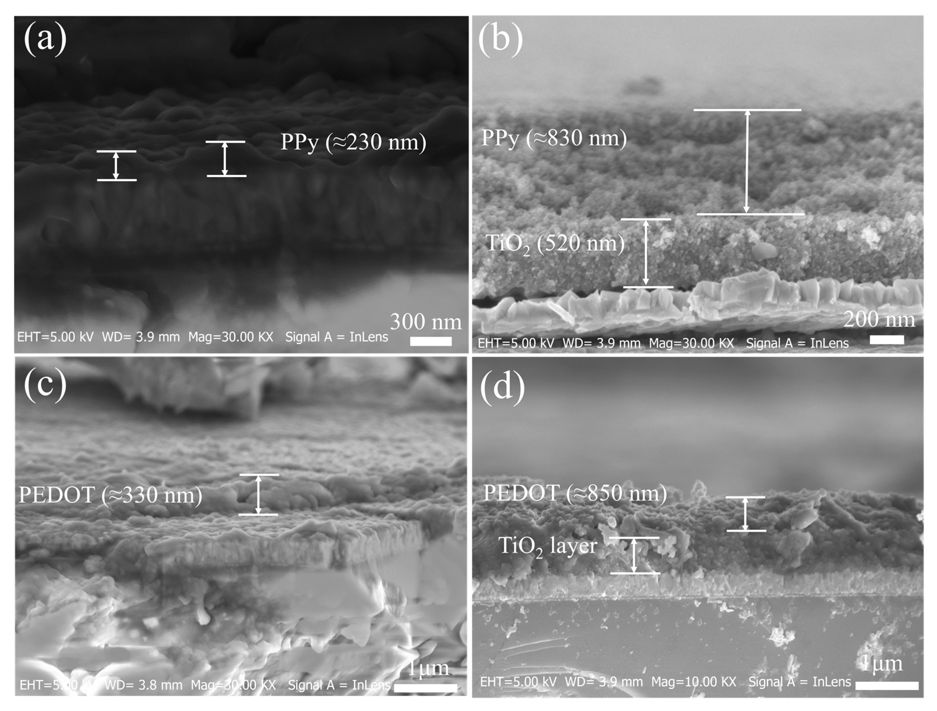
2.1. Morphological Analysis of the Electrodeposited CEs

The purpose of this work is to provide a porous template for the PEDOT and PPy films to increase the exposed surface area for the electrolyte, which is preferred for catalytic activity, and thus improve the total performance of the assembled DSSCs. The surface morphologies of the electrodeposited CEs (PPy, PEDOT, PPy@TiO2, and PEDOT@TiO2) were studied by FE-SEM; the images obtained are shown in Figure 2. The morphology of the electrodeposited PPy film in Figure 2a reveals a highly compact spherical-like dense structure. Despite the PEDOT film (Figure 2c) showing a porous and spherical-like structure, the deposited film appears to be disorderly coated on the FTO substrate. Such morphologies (compact, and disordered) are unfavorable for the catalytic activity as they limit the electron transfer and thus reduce the total photovoltaic performance of the assembled DSSCs. Compared with pristine PPy, and PEDOT films, the PPy@TiO2 and PEDOT@TiO2 (Figure 2b,d) display rougher, porous structures, revealing a higher electrochemical surface area available for reduction reactions, which is crucial for the photovoltaic performance of the DSSCs.
SEM cross-section images of the four electrodeposited films (PPy, PEDOT, PPy@TiO2, and PEDOT@TiO2) were obtained to determine the average thickness of the electrodeposited films. In this study, all CEs were prepared under the same conditions. From the cross-section SEM images in Figure 3, all films displayed high contact with the FTO substrate, which reveals the high stability of the prepared CEs. The average thickness of the screen-printed TiO2 is about 520 nm. The PPy (Figure 3a) and PEDOT (Figure 3c) layers displayed average thicknesses of 230 nm and 330 nm, respectively. Moreover, the electrodeposited films on the TiO2 template displayed a much higher thickness, revealing a much rougher surface, which is highly desirable for catalytic reactions. The estimated thickness of the PPy (Figure 3b) and PEDOT (Figure 3d) coated on the TiO2 layer are 830 nm and 850 nm, respectively.

2.2. Electrochemical Analysis

Generally, there are various techniques for investigating the electrochemical properties of the utilized CEs, such as CV, EIS, and Tafel plots. Cyclic voltammograms (CVs) were performed to investigate the electrocatalytic performance of the different deposited electrodes in an acetonitrile solution containing the Co2+/Co3+ redox couple. A typical CV curve for the redox reaction of the [Co(bpy)3]2+/3+ redox mediator has one redox peak due to this reaction being a one-electron transfer reaction. As shown in Figure 4a, and the related data presented in Table 1, the electrodeposited PPy and PEDOT CEs showed considerable catalytic activity toward the Co2+/Co3+ redox reaction. Furthermore, the recorded CV curves have a similar shape to that of Pt CE, indicating similar catalytic activity. In comparison with the thermally deposited Pt CE, the catalytic performance of PPy CE is lower, as evidenced by the lower peak current density (JPC), while the PEDOT displayed higher catalytic activity as indicated by a larger JPC (−0.631 mA cm 2). The potential difference between the anodic and cathodic redox peaks (∆EPP) for the PPy and the PEDOT CEs is lower than that for the Pt CE, which indicates a higher redox reaction rate [42]. As shown in Table 1, the electrocatalytic activity of the PPy and PEDOT CEs significantly enhanced after deposition onto the TiO2 film, as indicated by increasing the JPC from—0.482 mA cm−2 for pure PPy CE to—0.665 mA cm−2 for PPy@TiO2 CE, and from—0.631 mA cm−2 for pure PEDOT CE to—0.740 mA cm−2 for PEDOT@TiO2 CE. The higher current density indicates faster charge transfer at the CE surface due to the higher surface area [43,44]. As shown in Table 1, the ∆EPP for all deposited CEs is lower than that for the Pt CE; however, the values of both PPy@TiO2 and PEDOT@TiO2 CEs are still higher than the pure films, this can be assigned to lower conductivity due to the presence of the semiconducting TiO2 layer [43]. Among all CEs, the PEDOT@TiO2 CE displayed the best catalytic performance toward the Co2+/Co3+ redox reaction.
To evaluate the mechanism of the redox reactions of Co2+/Co3+ at the CE/electrolyte interface, the CVs of the PPy@TiO2 and PEDOT@TiO2 CEs at different scan rates were performed. The recorded CVs are presented in Supplementary Materials Figure S1a–d. As shown in Figure S1a,c a significant enhancement of the catalytic performance is indicated by the increasing JPC. Figure S1b,d also revealed linear correlations between the JPC, JOX, and the square root of the scan rate, indicating that the redox reactions at the CE/electrolyte interfaces are diffusion-limited for the transport of [Co(bpy)3]2+/3+ ions toward the CE, as described by the Randles–Sevcik theory (Equation (1)) [45]. This also suggests that the adsorption of [Co(bpy)3]2+/3+ species is hardly affected by the redox reaction on the CE surface and that there are no specific interactions between the Co 2 + / Co 3 + redox couple and the CE [46].
J PC = Kn 1.5 ACDn 0.5 υ 0.5
where K is the Boltzmann constant (2.69 × 10⁵ J K−1), A is the electrode surface area or the geometric surface area (cm2), υ is the scan rate (Vs−1), n is the number of electrons participating in the redox event, C is the bulk concentration of the analyte (mol cm−3), and D is the diffusion coefficient of the oxidized analyte (cm2 s−1).
To further confirm the catalytic activity and interfacial charge-transfer properties of the Co2+/Co3+ redox couple at the CE in a practical electrolyte used in the DSSCs, Tafel polarization plots were recorded at a low scan rate (10 mVs−1) using symmetrical electrochemical cells (CE/Electrolyte/CE). As shown in Figure 4b, the curve at a relatively moderate potential (120 mV < |V|< 400 mV) is assigned to the Tafel zone, where the exchange current density (Jo) can be determined by the intersection of the tangent line of the curve with the extension line of zero bias [27,47]. In the Tafel zone, Jo is used as an indicator for the electrocatalytic activity of the CEs [44]. As shown in Equation (2), the Jo value has an inverse relationship with the charge transfer resistance (RCT).
J o = RT nFR CT
where R is the general gas constant (8.3145 J mol−1 K−1), F is the Faraday constant (26.801 Ah mol−1), T is the Kelvin temperature, and n is the number of electrons involved in the redox reaction (here n = 1).
In the Tafel zone, the Log Jo is linearly correlated with voltage, and the steep slope of the Tafel zone reveals a larger Jo value, hence better electrocatalytic ability. As shown in Figure 4b and the estimated data in Table 1, the anodic and cathodic branches of the PPy CE show the smallest slope among all utilized CEs, while the slope of the PEDOT CE is better than that of the Pt CE. The larger slope indicates higher Jo values and, thus, lower RCT [27]. The slope of the log J-V plots for all PPy@TiO2 and PEDOT@TiO2 CEs is larger, resulting in higher Jo values and a lower RCT. As presented in Table 1, PEDOT@TiO2 CE displays the highest Jo and lowest RCT among all, which reveals the best catalytic activity toward the Co 2 + / Co 3 + redox couple.
The limiting current density (Jlim) is another important parameter that can be estimated from the Tafel plot at the limiting diffusion zone at high potential (|V| > 400 mV). The Jlim provides the maximum current that can flow from the DSSCs. The Jlim is usually obtained from the plateau current density in the high potential region of the Tafel plots [27]. Moreover, the diffusion coefficient (Dn) of the redox species is inversely dependent on the Jlim, as shown by Equation (3) [48].
Dn = L 2 nFC J lim
where L is the thickness of the diffusion layer (spacer), and C is the concentration of the oxidized species. Both n and F have the same meaning, as mentioned in Equation (2).
From the Tafel plots in Figure 3b and Table 1, the electrodeposited PPy and PEDOT CEs displayed almost the same Jlim values; however, the Jo of PEDOT is much better. After depositing the PPy and the PEDOT on the TiO2 film, the estimated Jlim values of the obtained PPy@TiO2 and PEDOT@TiO2 CEs are much higher than those for the Pt CE, which reflect the higher Dn of Co 3 + ions in the liquid electrolyte as described by Equation (3). As in Table 1, the estimated Dn of both PPy@TiO2 and PEDOT@TiO2 CEs are much better than that obtained by pure PPy, PEDOT CEs, and even higher than that for Pt CE. Overall, the higher Jo, Jlim, and Dn values of the PPy@TiO2 and PEDOT@TiO2 CEs indicate the positive influence of the TiO2 film.
As the main function of CE in a DSSC device is to catalyze the redox reaction at the CE/electrolyte interface, it is important to understand the mechanism of these reactions. EIS was performed to measure the intrinsic interfacial charge transfer and charge transport kinetics at the CE/electrolyte interface [47]. The recorded Nyquist plots of the assembled symmetric cells are shown in Figure 5a,b and the fitted data are summarized in Table 2. It can be noticed that the cells with PPy, PPy@TiO2, and Pt CEs showed two semicircles, while those with PEDOT, and PEDOT@TiO2 CEs exhibited three semicircles, indicating the porous structure of these electrodes. The intersection of the first semicircle at high frequency with the real axis represents the Ohm serial resistance (RS). From the first semicircle, the charge transfer resistance at the CE/electrolyte interface (RCT) and the constant phase element (CPE) can be estimated [49]. The middle-frequency semi-circuit represents the diffusion impedance (Zdiff) of the redox species on a 3D layer, while the semi-circuit in the low-frequency region is from the diffusion resistance of the redox species in the electrolyte between the two electrodes, the Nernst diffusion impedance (ZN) [44]. All assembled dummy cells have the same diffusion layer; thus, any decrease in ZN can be attributed to the diffusion of the redox couple in the electrolyte [50]. As listed in Table 2, the RS of the dummy cells with the electrodeposited pristine PPy and PEDOT CEs are slightly smaller than those with the PPy@TiO2 and PEDOT@TiO2 CEs, which reflects the influence of TiO2 as a supporting layer for both polymers. The RCT values of the cells with the electrodeposited PPy and PEDOT CE cells are 5.757 Ω and 5.655 Ω, respectively. Both are higher than that obtained by the cell with the Pt CE (5.618 Ω). This higher RCT can be attributed to the compact structure of the pristine polymer layers, which reveals lower catalytic activity. Moreover, the dummy cells with PPy@TiO2 and PEDOT@TiO2 CEs give lower values due to the porous structure.
The RCT is used as an indicator for the electrocatalytic activity of the catalytic layer toward the redox reaction of the Co2+/Co3+ redox couple, the lower RCT revealing higher catalytic activity of the CE toward the Co2+/Co3+ redox reaction and vice versa. The RCT of the cell with PEDOT@TiO2 CEs is the lowest (4.457 Ω), which implies the fastest charge transferability at the CE/electrolyte interface. These findings are in agreement with the Tafel and CV results, which support our claims that the catalytic performance can be boosted by depositing PPy and PEDOT onto a 3D hard template due to creating more active sites for the redox reaction [27]. As listed in Table 2, the ZN of the cells based on the PPy CE and the PEDOT CE are 7.811 Ω, and 6.554 Ω, respectively. The ZN of the assembled cells was reduced to 5.605 Ω and 5.115 Ω after depositing on TiO2 film porous support, indicating a lower interfacial recombination rate [51]. The cell with the Pt CE had the smallest value (3.278 Ω) of all. The Nyquist plots of the cells based on PEDOT, and PEDOT@TiO2 CEs showed three semi-circuits, indicating a porous structure. The estimated Zdiff of the cell with PEDOT CE (13.059 Ω) was reduced to 6.792 Ω after depositing on TiO2, demonstrating the importance of TiO2 as a supporting layer.
Sets of DSSCs were assembled and tested to assess the effectiveness of the prepared films as counter electrodes. The recorded photocurrent–voltage (J–V) curves are shown in Figure 6, and their related photovoltaic parameters are listed in Table 3. Among all devices, the DSSC with pristine PPy CE showed the lowest performance, with a PCE of 4.811%. This mainly arises from the low fill factor (FF = 69.041%) and low short circuit current (JSC = 8.611 mA cm 2), which agree with the previous literature [27]. Moreover, the device with the PEDOT CE displayed better performance with a PCE of 6.141%, which is close to that achieved by the device with the Pt CE (6.065%). By utilizing PPy@TiO2 and PEDOT@TiO2 CEs, the assembled devices showed much better performances, in agreement with the previous electrochemical analysis. The PCE of the assembled devices with PPy@TiO2 and PEDOT@TiO2 CEs were 6.332% and 6.617%, respectively. The device with the PEDOT@TiO2 CE displayed the highest performance among all.
The JSC is the distinguishing factor in the photovoltaic performance of the assembled devices, which can be assigned to the porous structures. Even though the VOC of the assembled devices was nearly identical, the FF values varied. The device with the pristine PPy CE displayed the lowest FF (69.041%), which can be assigned to the higher series resistance resulting from the high compactness of the surface [52]. In the presence of the TiO2 layer, a porous structure was formed, which significantly increased the FF to 72.004%. In the case of PEDOT-based devices, the insertion of TiO2 results in lowering the FF, which mainly can be attributed to reducing the conductivity. Carli et al. recently reported that a device with the electrodeposited PEDOT/Nafion CE had a PCE of 3.60% [35], which is significantly lower than the PCEs achieved by devices with a PPy@TiO2 CE (6.33%) and PEDOT@TiO2 CE (6.62%).

3. Materials and Methods

3.1. Materials and Methods

Pyrrole, 3,4-ethylenedioxythiophene (EDOT), H2SO4 (98%), and sodium dodecyl sulphate (SDS) were purchased from Sigma Aldrich Co., Shanghai, China. 4-tert-butylpyridine (4-tBP), titanium di-isopropoxide bis (acetylacetonate) (TAA) [(CH3)2CHO]2Ti (C5H7O2)2, 75 wt. % in isopropanol], bis (tri-fluoromethane) sulfonamide lithium salt (LiTFSI), hexachloroplatinic acid hexahydrate (H2PtCl6·6H2O, 37.50% Pt basis), 2-methylimidazole (98%), tert-butyl alcohol (C4H10O, 97%), 2,2′-bipyridine, (C10H8N2), nitrosonium tetrafluoroborate (NOBF4, 95%), cobalt chloride (CoCl2.6H2O, 97%), platinum chloride (H2PtCl6), silver nitrate (AgNO3, 99%), and MK-2 dye (C58H70N2O2S4) from Sigma Aldrich Co. China.Anhydrous acetonitrile (CH3CN, 99.80%) from Alfa Aesar, Beijing, China. Titanium dioxide paste (average particle size: 18, 30 nm, and 400 nm) and FTO conductive glass (2 mm thicknesses, square resistance 10–15 Ω·sq−1) from OPV Tech Co., Ltd. Yingkou, China. Titanium (IV) tetrachloride (TiCl4, 99.5–99.9%) from Sinopharm Chemical Reagent Beijing Co., Ltd., Beijing, China. De-ionized (DI) water was from an ultra-pure purifier (Ulu pure, Chengdu, China, resistivity ≥18.2 MΩ). All used reagents were of analytical purity and used as received from commercial sources without any further purification.

3.2. Working Electrodes and DSSCs

The working electrodes, or photoanodes, were prepared as previously described in our work [53]. Briefly, an FTO conducting glass plate was cut into pieces (1 cm × 1.5 cm) and washed with detergent, deionized (DI) water, and ethanol in a sequential process using an ultrasonic bath, followed by drying using a hot blower. A thin layer of TiO2 (as a blocking layer) was formed on the conductive side of the pre-cleaned FTO species via spray pyrolysis of 10% (v/v) solution of titanium isopropoxide bisacetyl acetonate in ethanol at 450 °C. The next layer (transparent layer) with ~6.0 µm thickness was formed by screen printing commercial TiO2 paste (20 nm-sized). The printing process was repeated five times, followed by annealing at 120 °C for 10 min. A scattering layer with ~6.0 µm thickness was formed by printing a commercial TiO2 paste (400 nm-sized) on top of a transparent layer and then heated at 120 °C for 10 min. The screen-printed TiO2 films with 0.16 cm2 active area were sintered at 500 °C for 30 min in a programmable system, followed by being treated in 20 mM TiCl4 (aq) bath at 70 °C for 30 min. After being cooled to room temperature, the nanocrystalline TiO2 electrode was washed with DI water and ethanol and fired again at 500 °C in the air for 30 min. Once cooled, the electrodes were bathed in a 0.3 mM solution of 0.3 mM MK-2 in absolute ethanol for 18 h at room temperature. The DSSCs were assembled by clipping the loaded dye TiO2 photoanode with a CE using a 25 μm thick spacer (Solaronix SA, Aubonne, Switzerland) with inner of dimensions 5 × 6 mm. A liquid electrolyte of acetonitrile was injected into the gap between the clipping electrodes.

3.3. Preparation of PPy@TiO2 and PEDOT@TiO2 Counter Electrodes

The PPy@TiO2 and PEDOT@TiO2 CEs were prepared in two steps, as described below. First, a commercial TiO2 paste (20 nm-sized) was screen printed onto cleaned FTO-glass substrates (10–15 Ω/□). The printed films were then annealed at 250 °C to remove the organic compounds, and finally subjected to further annealing at 500 °C for 30 min in the programmable system. The thickness of the printed TiO2 layer was about 210–230 nm. The PPy and PEDOT were then electrodeposited on top of the TiO2 using a three-electrode cell in which Pt foil served as the CE, an Ag/AgCl electrode served as the reference electrode, and FTO served as the working electrode. For PEDOT, the base electrodeposition solution consisted of 10 mM 3, 4-ethylenedioxythiophene (EDOT), 10 mM concentrated H2SO4, 100 mM LiTFSI, and 10 mM SDS in 20 mL DI water; the mixture was kept under an ultrasonic bath for 30 min. SDS, an anionic surfactant, was used as a dispersant, resulting in a homogeneous mixture of EDOT and water and lowering its oxidation potential to less than 1.0 V. Electrodeposition was performed at 1.1 V for 30 s; the electrodeposited electrodes were rinsed with absolute ethanol and dried in the atmosphere at room temperature.
For PPy, the base electrodeposition solution consisted of 10 mM of pyrrole, 10 mM concentrated H2SO4, 100 mM LiTFSI, and 10 mM SDS in 20 mL DI water; the mixture was treated using ultrasonication for 30 min. Electrodeposition was performed at 0.75 V for 30 s. The electrodeposited electrodes were rinsed with absolute ethanol and dried in the atmosphere at room temperature. The whole process utilized to prepare the electrodeposited electrodes is presented in Figure 7. For comparison, the pristine PEDOT PPy CEs were prepared using similar methods as the PPy@TiO2 electrode. Furthermore, for compression, Pt CEs were prepared by the thermal decomposition of 10 mM of H2PtCl6 in ethanol at 380 °C for 30 min [1].

3.4. Characterization and Measurements

The surface morphologies were investigated by a field emission scanning electron microscope (SEM) JSM 7100F FESEM (Zeiss Ultra Plus) equipped with an energy dispersive spectrum (EDS) analyzer. The CV of the prepared CEs was performed by a conventional three-electrode electrochemical cell on the CHI760D electrochemical workstation. Ag/Ag+ served as the reference electrode, Pt coil as the counter electrode, and the as-prepared CEs as the working electrodes in nitrogen-purged anhydrous acetonitrile solution of 50 mM [Co(bpy)3] (TFSI)2, 50 mM [Co (bpy)3] (TFSI)3, and 100 mM LiTFSI supporting electrolyte for the [Co(bpy)3]2+/3+ redox system. CV curves were recorded in the potential range from + 0.6 V to −0.6 V at a 50 mVs−1 scan rate. Electrochemical impedance spectroscopy (EIS) of the symmetric cells was performed on an Ametek 1260 EIS instrument in a frequency range from 0.1 Hz to 100 KHz with 10 mV AC amplitude at zero bias potential under dark conditions. Z-view software was used to fit the impedance spectra by using a suitable equivalent circuit. The Tafel polarization test was performed on the electrochemical workstation with a 100 mVs−1 scan rate. The photocurrent density–voltage (J–V) curves of the DSSCs were recorded using the Newport solar simulator, USA (450 W Xe source) with a Keithley 2400 source meter, under irradiation (AM 1.5G, 0.1 Wcm−2 light radiation intensity). The light intensity was adjusted by a standard Si solar cell.

4. Conclusions

Here, PPy and PEDOT films were separately successfully electrodeposited on TiO2 as a 3D porous template to be utilized as CEs for DSSCs based on the [Co(bpy)3]2+/3+ redox couple. The morphological study indicated that the prepared films show a uniform porous structure, resulting in enhanced contact with the electrolyte and thus better electron transport. Electrochemical analysis demonstrated that the porous TiO2 layer significantly enhanced the electrocatalytic activity of both PPy and PEDOT toward the [Co(bpy)3]2+/3+ redox systems with much lower charge transfer resistance. This can be attributed to the synergistic effect between the high catalytic activity of PPy and PEDOT and the large surface area of the TiO2 layer. The electrocatalytic performance of both PPy@TiO2 and PEDOT@TiO2 CEs outperformed the Pt CE with lower charge transfer resistances, and thus the assembled devices displayed higher power conversion efficiency. The PCE of the assembled DSSCs with the PPy@TiO2 and PEDOT@TiO2 CE are 6.33% and 6.62%, respectively; both are higher than that achieved with the Pt CE (6.07%), which highlights the potential use of these low-cost films for DSSCs with cobalt-based electrolytes.

Supplementary Materials

The following supporting information can be downloaded at: https://www.mdpi.com/article/10.3390/inorganics10110213/s1, The CV curves for both PPy@TiO2 and PEDOT@TiO2 CEs at different scan rates and their relationship between peak current density and the square root of scan rates are in supporting information, Figure S1.

Author Contributions

Formal analysis, A.S.A.A., X.Y. and W.X.; Funding acquisition, X.Z.; Methodology, A.S.A.A.; Software, X.Y.; Supervision, X.Z. and M.A.; Validation, M.A.; Visualization, W.X.; Writing—original draft, A.S.A.A.; Writing—review & editing, W.X. All authors have read and agreed to the published version of the manuscript.

Funding

This research received no external funding.

Institutional Review Board Statement

Not applicable.

Informed Consent Statement

Not applicable.

Data Availability Statement

Not applicable.

Acknowledgments

The authors gratefully acknowledge W. Xiang for providing Co electrolyte. They also wish to thank Mohamed Taher for providing pyrrole and sodium dodecyl sulphate (SDS), as well as helping with the electropolymerizing technique.

Conflicts of Interest

The authors declare no conflict of interest.

References

  1. Hagfeldt, A.; Boschloo, G.; Sun, L.; Kloo, L.; Pettersson, H. Dye-Sensitized Solar Cells. Chem. Rev. 2010, 110, 6595–6663. [Google Scholar] [CrossRef] [PubMed]
  2. Grätzel, M. Photoelectrochemical cells. Nature 2001, 414, 338–344. [Google Scholar] [CrossRef] [PubMed]
  3. O’Regan, B.; Grätzel, M. A low-cost, high-efficiency solar cell based on dye-sensitized colloidal TiO2 films. Nature 1991, 353, 737–740. [Google Scholar] [CrossRef]
  4. Ito, S.; Chen, P.; Comte, P.; Nazeeruddin, M.K.; Liska, P.; Péchy, P.; Grätzel, M. Fabrication of screen-printing pastes from TiO2 powders for dye-sensitised solar cells. Prog. Photovolt. Res. Appl. 2007, 15, 603–612. [Google Scholar] [CrossRef]
  5. Mathew, S.; Yella, A.; Gao, P.; Humphry-Baker, R.; Curchod, B.F.; Ashari-Astani, N.; Tavernelli, I.; Rothlisberger, U.; Nazeeruddin, M.K.; Grätzel, M. Dye-sensitized solar cells with 13% efficiency achieved through the molecular engineering of porphyrin sensitizers. Nat. Chem. 2014, 6, 242–247. [Google Scholar] [CrossRef] [PubMed] [Green Version]
  6. Zhang, L.; Yang, X.; Wang, W.; Gurzadyan, G.G.; Li, J.; Li, X.; An, J.; Yu, Z.; Wang, H.; Cai, B.; et al. 13.6% Efficient Organic Dye-Sensitized Solar Cells by Minimizing Energy Losses of the Excited State. ACS Energy Lett. 2019, 4, 943–951. [Google Scholar] [CrossRef]
  7. Murakami, T.N.; Grätzel, M. Counter electrodes for DSC: Application of functional materials as catalysts. Inorg. Chim. Acta 2008, 361, 572–580. [Google Scholar] [CrossRef]
  8. Wu, J.; Lan, Z.; Lin, J.; Huang, M.; Huang, Y.; Fan, L.; Luo, G.; Lin, Y.; Xie, Y.; Wei, Y. Counter electrodes in dye-sensitized solar cells. Chem. Soc. Rev. 2017, 46, 5975–6023. [Google Scholar] [CrossRef] [Green Version]
  9. Thomas, S.; Deepak, T.G.; Anjusree, G.S.; Arun, T.A.; Nair, S.V.; Nair, A.S. A review on counter electrode materials in dye-sensitized solar cells. J. Mater. Chem. A 2014, 2, 4474–4490. [Google Scholar] [CrossRef]
  10. Green, M.A.; Emery, K.; Hishikawa, Y.; Warta, W.; Dunlop, E.D. Solar cell efficiency tables (version 47). Prog. Photovolt. Res. Appl. 2016, 24, 3–11. [Google Scholar] [CrossRef]
  11. Thogiti, S.; Park, J.Y.; Thanh Thuy, C.T.; Lee, D.K.; Min, B.-K.; Yun, H.J.; Kim, J.H. High-Performance Dye-Sensitized Solar Cells through Graded Electron Transport in Band-Engineered W-TiO2 Cascade Layer. ACS Sustain. Chem. Eng. 2018, 6, 13025–13034. [Google Scholar] [CrossRef]
  12. Gurulakshmi, M.; Meenakshamma, A.; Susmitha, K.; Venkata Subbaiah, Y.P.; Mitty, R. Enhanced Performance of Dye-Sensitized Solar Cells (DSSCs) Based on MoS2/Single-Walled Carbon Nanohorns Electrochemically Deposited on Bilayer Counter Electrodes. Chem. Plus Chem. 2020, 85, 2599–2605. [Google Scholar] [CrossRef] [PubMed]
  13. Wang, M.; Grätzel, C.; Zakeeruddin, S.M.; Grätzel, M. Recent developments in redox electrolytes for dye-sensitized solar cells. Energy Environ. Sci. 2012, 5, 9394–9405. [Google Scholar] [CrossRef]
  14. Spokoyny, A.M.; Li, T.C.; Farha, O.K.; Machan, C.W.; She, C.; Stern, C.L.; Marks, T.J.; Hupp, J.T.; Mirkin, C.A. Electronic Tuning of Nickel-Based Bis(dicarbollide) Redox Shuttles in Dye-Sensitized Solar Cells. Angew. Chem. Int. Ed. 2010, 49, 5339–5343. [Google Scholar] [CrossRef] [PubMed]
  15. Saygili, Y.; Söderberg, M.; Pellet, N.; Giordano, F.; Cao, Y.; Muñoz-García, A.B.; Zakeeruddin, S.M.; Vlachopoulos, N.; Pavone, M.; Boschloo, G.; et al. Copper Bipyridyl Redox Mediators for Dye-Sensitized Solar Cells with High Photovoltage. J. Am. Chem. Soc. 2016, 138, 15087–15096. [Google Scholar] [CrossRef] [Green Version]
  16. Wang, M.; Chamberland, N.; Breau, L.; Moser, J.E.; Humphry-Baker, R.; Marsan, B.; Zakeeruddin, S.M.; Grätzel, M. An organic redox electrolyte to rival triiodide/iodide in dye-sensitized solar cells. Nat. Chem. 2010, 2, 385–389. [Google Scholar] [CrossRef] [Green Version]
  17. Daeneke, T.; Kwon, T.H.; Holmes, A.B.; Duffy, N.W.; Bach, U.; Spiccia, L. High-efficiency dye-sensitized solar cells with ferrocene-based electrolytes. Nat. Chem. 2011, 3, 211–215. [Google Scholar] [CrossRef]
  18. Bella, F.; Galliano, S.; Gerbaldi, C.; Viscardi, G. Cobalt-Based Electrolytes for Dye-Sensitized Solar Cells: Recent Advances towards Stable Devices. Energies 2016, 9, 384. [Google Scholar] [CrossRef] [Green Version]
  19. Nusbaumer, H.; Moser, J.-E.; Zakeeruddin, S.M.; Nazeeruddin, M.K.; Grätzel, M. CoII(dbbip)22+ Complex Rivals Tri-iodide/Iodide Redox Mediator in Dye-Sensitized Photovoltaic Cells. J. Phys. Chem. B 2001, 105, 10461–10464. [Google Scholar] [CrossRef]
  20. Klahr, B.M.; Hamann, T.W. Performance Enhancement and Limitations of Cobalt Bipyridyl Redox Shuttles in Dye-Sensitized Solar Cells. J. Phys. Chem. C 2009, 113, 14040–14045. [Google Scholar] [CrossRef]
  21. Tsao, H.N.; Yi, C.; Moehl, T.; Yum, J.H.; Zakeeruddin, S.M.; Nazeeruddin, M.K.; Grätzel, M. Cyclopentadithiophene bridged donor-acceptor dyes achieve high power conversion efficiencies in dye-sensitized solar cells based on the tris-cobalt bipyridine redox couple. Chem. Sus. Chem. 2011, 4, 591–594. [Google Scholar] [CrossRef] [PubMed]
  22. Sapp, S.A.; Elliott, C.M.; Contado, C.; Caramori, S.; Bignozzi, C.A. Substituted Polypyridine Complexes of Cobalt(II/III) as Efficient Electron-Transfer Mediators in Dye-Sensitized Solar Cells. J. Am. Chem. Soc. 2002, 124, 11215–11222. [Google Scholar] [CrossRef] [PubMed]
  23. Feldt, S.M.; Gibson, E.A.; Gabrielsson, E.; Sun, L.; Boschloo, G.; Hagfeldt, A. Design of Organic Dyes and Cobalt Polypyridine Redox Mediators for High-Efficiency Dye-Sensitized Solar Cells. J. Am. Chem. Soc. 2010, 132, 16714–16724. [Google Scholar] [CrossRef] [PubMed]
  24. Yella, A.; Lee, H.W.; Tsao, H.N.; Yi, C.; Chandiran, A.K.; Nazeeruddin, M.K.; Diau, E.W.; Yeh, C.Y.; Zakeeruddin, S.M.; Grätzel, M. Porphyrin-sensitized solar cells with cobalt (II/III)-based redox electrolyte exceed 12 percent efficiency. Science 2011, 334, 629–634. [Google Scholar] [CrossRef]
  25. Baptayev, B.; Mustazheb, D.; Balanay, M.P. Binary transition metal sulfides as an economical Pt-free counter electrodes for dye-sensitized solar cells. Mater. Today Proc. 2020, 25, 24–27. [Google Scholar] [CrossRef]
  26. Hattori, S.; Wada, Y.; Yanagida, S.; Fukuzumi, S. Blue Copper Model Complexes with Distorted Tetragonal Geometry Acting as Effective Electron-Transfer Mediators in Dye-Sensitized Solar Cells. J. Am. Chem. Soc. 2005, 127, 9648–9654. [Google Scholar] [CrossRef]
  27. He, J.; Pringle, J.M.; Cheng, Y.-B. Titanium Carbide and Titanium Nitride-Based Nanocomposites as Efficient Catalysts for the Co2+/Co3+ Redox Couple in Dye-Sensitized Solar Cells. J. Phys. Chem. C 2014, 118, 16818–16824. [Google Scholar] [CrossRef]
  28. Carli, S.; Busatto, E.; Caramori, S.; Boaretto, R.; Argazzi, R.; Timpson, C.J.; Bignozzi, C.A. Comparative Evaluation of Catalytic Counter Electrodes for Co(III)/(II) Electron Shuttles in Regenerative Photoelectrochemical Cells. J. Phys. Chem. C 2013, 117, 5142–5153. [Google Scholar] [CrossRef]
  29. Lu, S.; Yang, H.; Li, F.; Wang, Y.; Chen, S.; Yang, G.; Liu, Y.; Zhang, X. Element substitution of kesterite Cu2ZnSnS4 for efficient counter electrode of dye-sensitized solar cells. Sci. Rep. 2018, 8, 8714. [Google Scholar] [CrossRef] [Green Version]
  30. Huang, Y.-J.; Chen, H.-T.; Ann, S.-B.; Li, C.-T.; Lin, J.T.; Lee, C.-P.; Ho, K.-C. Hierarchical urchin-like CoSe2/CoSeO3 electro-catalysts for dye-sensitized solar cells: Up to 19% PCE under dim light illumination. J. Mater. Chem. A 2019, 7, 26089–26097. [Google Scholar] [CrossRef]
  31. Pang, B.; Zhang, M.; Zhou, C.; Dong, H.; Ma, S.; Shi, Y.; Sun, Q.; Li, F.; Yu, L.; Dong, L. Nitrogen-Doped Carbon Nano-Onions Decorated on Graphene Network: A Novel All-Carbon Composite Counter Electrode for Dye-Sensitized Solar Cell with a 10.28% Power Conversion Efficiency. Sol. RRL 2020, 4, 2000263. [Google Scholar] [CrossRef]
  32. Ahmed, A.S.A.; Xiang, W.; Abdelmotalleib, M.; Zhao, X. Efficient NiO Impregnated Walnut Shell-Derived Carbon for Dye-Sensitized Solar Cells. ACS Appl. Electron. Mater. 2022, 4, 1063–1071. [Google Scholar] [CrossRef]
  33. Ahmed, A.S.A.; Xiang, W.; Gu, A.; Hu, X.; Saana, I.A.; Zhao, X. Carbon black/silicon nitride nanocomposites as high-efficiency counter electrodes for dye-sensitized solar cells. New J. Chem. 2018, 42, 11715–11723. [Google Scholar] [CrossRef]
  34. Abdelaal, S.A.A.; Wanchun, X.; Fatma, S.M.H.; Xiujian, Z. Screen-printed carbon black/SiO2 composite counter electrodes for dye-sensitized solar cells. Sol. Energy 2021, 230, 902–911. [Google Scholar] [CrossRef]
  35. Marchini, E.; Orlandi, M.; Bazzanella, N.; Boaretto, R.; Cristino, V.; Miotello, A.; Caramori, S.; Carli, S. Electrodeposited PEDOT/Nafion as Catalytic Counter Electrodes for Cobalt and Copper Bipyridyl Redox Mediators in Dye-Sensitized Solar Cells. ACS Omega 2022, 7, 29181–29194. [Google Scholar] [CrossRef] [PubMed]
  36. Kavan, L.; Yum, J.H.; Grätzel, M. Graphene nanoplatelets outperforming platinum as the electrocatalyst in co-bipyridine-mediated dye-sensitized solar cells. Nano Lett. 2011, 11, 5501–5506. [Google Scholar] [CrossRef] [PubMed]
  37. Ju, M.J.; Kim, J.C.; Choi, H.-J.; Choi, I.T.; Kim, S.G.; Lim, K.; Ko, J.; Lee, J.-J.; Jeon, I.-Y.; Baek, J.-B.; et al. N-Doped Graphene Nanoplatelets as Superior Metal-Free Counter Electrodes for Organic Dye-Sensitized Solar Cells. ACS Nano 2013, 7, 5243–5250. [Google Scholar] [CrossRef]
  38. Liu, I.P.; Hou, Y.-C.; Li, C.-W.; Lee, Y.-L. Highly electrocatalytic counter electrodes based on carbon black for cobalt(iii)/(ii)-mediated dye-sensitized solar cells. J. Mater. Chem. A 2017, 5, 240–249. [Google Scholar] [CrossRef]
  39. Li, Y.; Feng, Q.; Wang, H.; Zhou, G.; Wang, Z.-S. Reduced graphene oxide–Ta3N5 composite: A potential cathode for efficient Co(bpy)33+/2+ mediated dye-sensitized solar cells. J. Mater. Chem. A 2013, 1, 6342–6349. [Google Scholar] [CrossRef]
  40. Marchini, E.; Caramori, S.; Bignozzi, C.A.; Carli, S. On the Use of PEDOT as a Catalytic Counter Electrode Material in Dye-Sensitized Solar Cells. Appl. Sci. 2021, 11, 3795. [Google Scholar] [CrossRef]
  41. Park, B.-w.; Pazoki, M.; Aitola, K.; Jeong, S.; Johansson, E.M.J.; Hagfeldt, A.; Boschloo, G. Understanding Interfacial Charge Transfer between Metallic PEDOT Counter Electrodes and a Cobalt Redox Shuttle in Dye-Sensitized Solar Cells. ACS Appl. Mater. Interfaces 2014, 6, 2074–2079. [Google Scholar] [CrossRef] [PubMed]
  42. Reinmuth, W.H. Theory of Stationary Electrode Polarography. Anal. Chem. 1961, 33, 1793–1794. [Google Scholar] [CrossRef]
  43. Peng, S.; Tian, L.; Liang, J.; Mhaisalkar, S.G.; Ramakrishna, S. Polypyrrole nanorod networks/carbon nanoparticles composite counter electrodes for high-efficiency dye-sensitized solar cells. ACS Appl. Mater Interfaces 2012, 4, 397–404. [Google Scholar] [CrossRef] [PubMed]
  44. Wu, M.; Lin, X.; Wang, Y.; Wang, L.; Guo, W.; Qi, D.; Peng, X.; Hagfeldt, A.; Grätzel, M.; Ma, T. Economical Pt-Free Catalysts for Counter Electrodes of Dye-Sensitized Solar Cells. J. Am. Chem. Soc. 2012, 134, 3419–3428. [Google Scholar] [CrossRef]
  45. Huang, S.; He, Q.; Chen, W.; Zai, J.; Qiao, Q.; Qian, X. 3D hierarchical FeSe2 microspheres: Controlled synthesis and applications in dye-sensitized solar cells. Nano Energy 2015, 15, 205–215. [Google Scholar] [CrossRef]
  46. Afshari, M.; Dinari, M.; Momeni, M.M. Ultrasonic irradiation preparation of graphitic-C3N4/polyaniline nanocomposites as counter electrodes for dye-sensitized solar cells. Ultrason. Sonochem. 2018, 42, 631–639. [Google Scholar] [CrossRef]
  47. He, Q.; Huang, S.; Wang, C.; Qiao, Q.; Liang, N.; Xu, M.; Chen, W.; Zai, J.; Qian, X. The role of Mott-Schottky heterojunctions in Ag-Ag8SnS6 as counter electrodes in dye-sensitized solar cells. ChemSusChem 2015, 8, 817–820. [Google Scholar] [CrossRef]
  48. He, B.; Tang, Q.; Wang, M.; Chen, H.; Yuan, S. Robust Polyaniline–Graphene Complex Counter Electrodes For Efficient Dye-Sensitized Solar Cells. ACS Appl. Mater. Interfaces 2014, 6, 8230–8236. [Google Scholar] [CrossRef]
  49. Kavan, L.; Yum, J.H.; Graetzel, M. Optically transparent cathode for Co(III/II) mediated dye-sensitized solar cells based on graphene oxide. ACS Appl. Mater. Interfaces 2012, 4, 6999–7006. [Google Scholar] [CrossRef]
  50. Wu, M.; Wang, Y.; Lin, X.; Guo, W.; Wu, K.; Lin, Y.-N.; Guo, H.; Ma, T. TiC/Pt composite catalyst as counter electrode for dye-sensitized solar cells with long-term stability and high efficiency. J. Mater. Chem. A 2013, 1, 9672–9679. [Google Scholar] [CrossRef]
  51. Huang, S.; Zai, J.; Ma, D.; Hu, Z.; He, Q.; Wu, M.; Chen, D.; Chen, Z.; Qian, X. Improving the catalytic performance of Ni3S4-PtCo heteronanorods via Mott-Schottky effect toward the reduction of iodine couples in dye-sensitized solar cells. Electrochim. Acta 2017, 241, 89–97. [Google Scholar] [CrossRef]
  52. Aftabuzzaman, M.; Sarker, S.; Lu, C.; Kim, H.K. In-depth understanding of the energy loss and efficiency limit of dye-sensitized solar cells under outdoor and indoor conditions. J. Mater. Chem. A 2021, 9, 24830–24848. [Google Scholar] [CrossRef]
  53. Ahmed, A.S.A.; Xiang, W.; Shui, F.; Li, B.; Younes, H.H.A.; Amiinu, I.S.; Zhao, X. MoS2/ZIF-8 derived nitrogen doped carbon (NC)-PEDOT: PSS as optically transparent counter electrode for dye-sensitized solar cells. Sol. Energy 2021, 218, 117–128. [Google Scholar] [CrossRef]
Figure 1. Schematic representation of DSSC device showing photoanode and counter electrode with an electrolyte sandwiched in the gap between them.
Inorganics 10 00213 g001
Figure 2. SEM images of (a) PPy film, (b) PPy@TiO2 film, (c) PEDOT film, and (d) PEDOT@TiO2 film (the inserted images in b, d are the photographs of PPy@TiO2 and PEDOT@TiO2 films, respectively).
Inorganics 10 00213 g002
Figure 3. SEM images of cross-section of (a) PPy film (230 nm), (b) PPy@TiO2 film, (c) PEDOT film (330 nm), and (d) PEDOT@TiO2 film.
Inorganics 10 00213 g003
Figure 4. (a) Cyclic voltammograms for the redox reaction of [Co(bpy)3]2+/3+ and (b) Tafel polarization plots for the symmetrical cells with Pt, PPy, PEDOT, PPy@TiO2, and PEDOT@TiO2 CEs.
Inorganics 10 00213 g004
Figure 5. Nyquist plots of symmetric cells with (a) Pt, PPy, PEDOT, PPy@TiO2, and (b) Pt, PEDOT@TiO2 CEs (The inside upper is the equivalent circuit used for fitting the Nyquist plots).
Inorganics 10 00213 g005
Figure 6. Photocurrent–voltage (J–V) curves of DSSCs with various counter electrodes.
Inorganics 10 00213 g006
Figure 7. The Schematic representation for the preparation of PPy and PEDOT via electrodeposition process.
Inorganics 10 00213 g007
Table 1. CV, and Tafel parameters of the symmetric cells with various CEs and [Co(bpy)3]2+/3+ redox couple.
CEsJPC
(mA cm−2)
∆EPP
(mV)
Log Jo
(mA cm−2)
Log Jlim
(mA cm−2)
Dn
(cm−2 S−1)
Pt−0.5590.319−0.1170.4355.88 × 10−7
PPy−0.4820.251−0.2830.3344.74 × 10−7
PPy@TiO2 layer−0.6650.2910.2750.4926.72 × 10−7
PEDOT−0.6310.160.1560.3444.77 × 10−7
PEDOT @TiO2 layer−0.7400.210.3510.5317.46 × 0−7
Table 2. EIS parameters of the symmetric cells with various CEs and [Co(bpy)3]2+/3+ redox couple.
CEsRS
(Ω)
RCT
(Ω)
Zdiff
(Ω)
ZN
(Ω)
Pt7.8685.618-------3.278
PPy12.3505.757-------7.811
PPy@TiO2 layer13.4305.007-------5.605
PEDOT7.4435.65513.0596.554
PEDOT @TiO2 layer8.0004.4576.7925.115
Table 3. Photovoltaic parameters of DSSCs with various CEs and [Co(bpy)3]2+/3+ redox couple.
CEVOC
(V)
JSC
(mA cm−2)
FF
(%)
PCE
(%)
Pt0.81110.16173.5786.065
PPy0.8098.61169.0414.811
PPy@TiO2 layer0.80510.92472.0046.332
PEDOT0.81110.28973.5996.141
PEDOT @TiO2 layer0.80911.22272.8726.617
Publisher’s Note: MDPI stays neutral with regard to jurisdictional claims in published maps and institutional affiliations.

