1. Introduction
Impinging jets have many industrial applications since they can enhance fluid mixing and increasing the spread rate of the resultant jet. The application of impinging jets has been found in space propulsion rocket fuel–oxidizer mixing chamber, in internal combustion engines and in spray generation. The team at ESI (Engineering & Scientific Innovations, Inc., Fairfield, OH, USA) is currently looking at establishing the use of impinging jets as mechanism for fire suppressant discharge.
Previously, the authors have done analysis on single round jet at low Reynolds number [
1], which acts as the predecessor for the current work. In addition, the work done by Disimile et al. [
2] has provided insight into the spread characteristics of the resultant jet after impingement at constant Reynolds number of 7500. They studied the round impinging jets at two angles: 30 and 45 degrees. They observed that the growth characteristics of the resultant jet along plane normal to impingement plane for 45-degree impingement case was approximately 50% greater than the 30-degree impingement case. They also observed an elliptical profile for the resultant jet, similar to the observation made by Rho et al. [
3], with major axis of the ellipse being 2.5 times greater than the minor axis in the case of 45-degree impingement configuration and 1.6 times the minor axis for the 30-degree impingement case. The significant difference in growth along the major axis when compared with minor axis for two different impingement angles is an indicator of its effect on the resultant jet characteristics.
Rho et al. [
3] performed an experimental study on cross jet mixing flows exiting nozzle condition. They considered circular nozzles and an impingement angle of 45-degrees for their study. The Reynolds numbers considered for the case under study were 52,000 and 65,000. They also observed an elliptical profile for the resultant jet after impingement, which has consistently been noted by other researchers. The shape of the resultant jet was observed to shift from an elliptical to circular profile further downstream. It was also concluded that, beyond the impingement zone, the mean velocity profile can be correlated to semi-empirical equations based on jet half-width.
Landers and Disimile [
4,
5,
6,
7] performed a significant amount of research on the near field of single jets, which was used as the baseline case for their work on impinging jets. Landers [
8] congregated the results from the above-mentioned studies into his thesis based on the experimental analysis performed on impinging jets at various angles. Hence, for the current study, experimental data from Landers’s [
8] study are used for the validation of results obtained from CFD analysis to ensure reasonable agreement.
Rajaratnam of University of Alberta has performed significant research on topics related to turbulent jets in general and impinging jets in particular. His book on turbulent jets [
9] has been an ideal technical source for the single jet study. Rajaratnam and Khan [
10] studied impinging jets at four different angles (30, 60, 90 and 120 degrees) at Reynolds number of 30,000. They established the physics of the flow based on two regions: a zone from nozzle exit to impingement point and a zone beyond impingement point. Detailed observations related to pressure and velocity characteristics were made in these regions for analysis. They observed that, beyond the impingement point, the growth of the jet in the plane normal to the plane of nozzles was thrice the growth observed along the plane of nozzles. In addition, as they moved further downstream, the flow tended to become axisymmetric with growth rate persisting at 1.5 times the growth rate for single round jet.
Rajaratnam and Wu [
11] performed ab experimental study on impinging jets at 60-degree angle with unequal momentum. They considered incompressible flows with different velocities exiting each nozzle. The velocities studied ranged from 0 to 42 m/s and the ratios of velocities considered were 0.39, 0.47, 0.59, 0.68 and 0.79. Hence, none of their tests considered symmetric profile. Similar to Rajaratnam and Khan’s study [
10], the physics of the flow was established based on the location with respect to impingement point. Beyond impingement point, they observed that the resultant jet axis can be predicted using momentum considerations. They observed that the growth of the jet in plane of the nozzle did not significantly depend on the velocity ratio. However, along the plane normal to the plane of nozzle, they were able to establish direct correlation between the velocity ratio and growth profile. Similar to the observation made in [
10], the growth of the combined jet in the plane normal to the plane of nozzles was significantly more than the growth in the plane of the nozzles.
Elangovan et al. [
12] presented their work on interaction of twin intersecting axisymmetric turbulent jets at low Mach numbers (0.2). The exit diameter of the nozzles was 10 mm each and the spacing between the centerlines of the nozzles was 31 mm with impingement angles considered being 0, 10, 20 and 30 degrees. They established three zones based on jet interactions—merging region, combining region and combined region. It was noted that significant recirculation occurs in the merging region with ambient flow entrainment into the free shear layers of jets. At the Merging Point (MP), the free shear layers of individual jet interact with one another. Combining region was defined as the zone beyond MP extending up to the location where the centerline velocity becomes maximum. This location was defined as Combining Point (CP). Beyond CP, the region was characterized by the resultant jet resembling a single jet flow.
They observed that the near field flow physics was strongly dependent on the impingement angle, and that the resultant flow field downstream of combining point resembled elliptic profile. They also observed the axis-switching characteristics, which is considered a phenomenon closely associated with non-circular jets. Similar to previous researchers, they observed that the growth of the resultant jets in the plane normal to nozzle plane was significantly higher than growth in nozzle plane. Regarding the entrainment of the ambient fluid into the jet shear layer, they observed that the entrainment was higher at lower angle, with maximum being at 0 degrees and consistently reduced with increasing impingement angle. Similarly, Elangovan et al. [
13] studied the effect of impingement angle and distance between nozzles centers for sonic and supersonic conditions.
An observation made by Landers [
8] that seems to be very astute is that only limited amount of published research work has been observed for impinging jets, either computational or experimental. Most of the published results available are very application-specific and mainly dealing with supersonic flows. Hence, obtaining a well-established dataset for validation has proven quite difficult for the case under consideration. Considering the ubiquitous nature of impinging jets in industrial applications, we can only conclude that the results, if any, have not been tabulated or published either because of the sensitive nature of application (such as spacecraft propulsion fuel mixing and defense-related research) or because of proprietary nature (such as impinging jets in combustion chambers of engines and spray formation systems). Hence, it was considered very significant to establish one of the initial works on impinging jets at low Reynolds number involving both computational and experimental analysis.
2. Computational Methodology
The current study was performed based on the insight gained from the analysis of single turbulent round jet (as discussed in [
1]) at low Reynolds number (Re) of 7500. Ansys Fluent (version 16.2), a commercial CFD solver, was used for the analysis. In the case of single jet study [
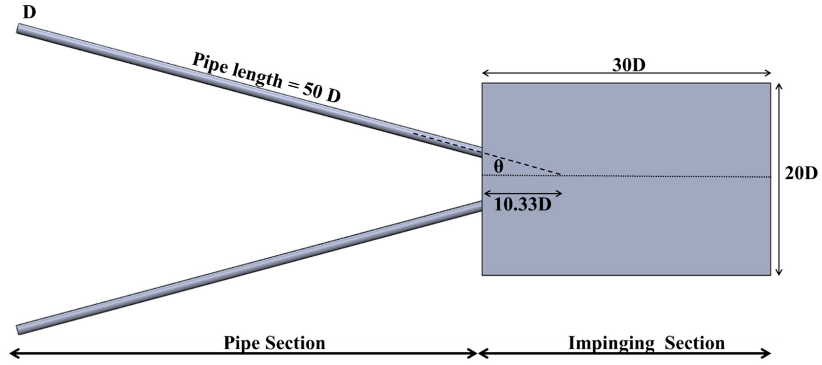
1], the inlet boundary condition was modeled as exiting from a fully developed pipe into ambient conditions. To obtain the velocity and Turbulent Kinetic Energy (TKE) profile of fully developed pipe, it was decided that the pipe flow be modeled separately and the profile from the pipe flow simulation used as the inlet condition for jet. The results from the study of single round jets were closely validated with experimental data which provided confidence that the strategy used was accurate. Hence, the same strategy was used in the case of impinging jet study. For the study of impinging jets, the full model generated is shown in
Figure 1. The pipe sections were separately analyzed first, followed by separate impinging jet domain. This methodology has successfully helped in reducing the computational requirements since the cases were treated separately.
As discussed earlier, the full geometry was initially modeled as a pipe and ambient domain. It was designed as a pipe with diameter D, length 50 D exiting into ambient air (at standard pressure and temperature) domain with length of 30 D and height and width parameter being 20 D each. The pipes are inclined at an angle of
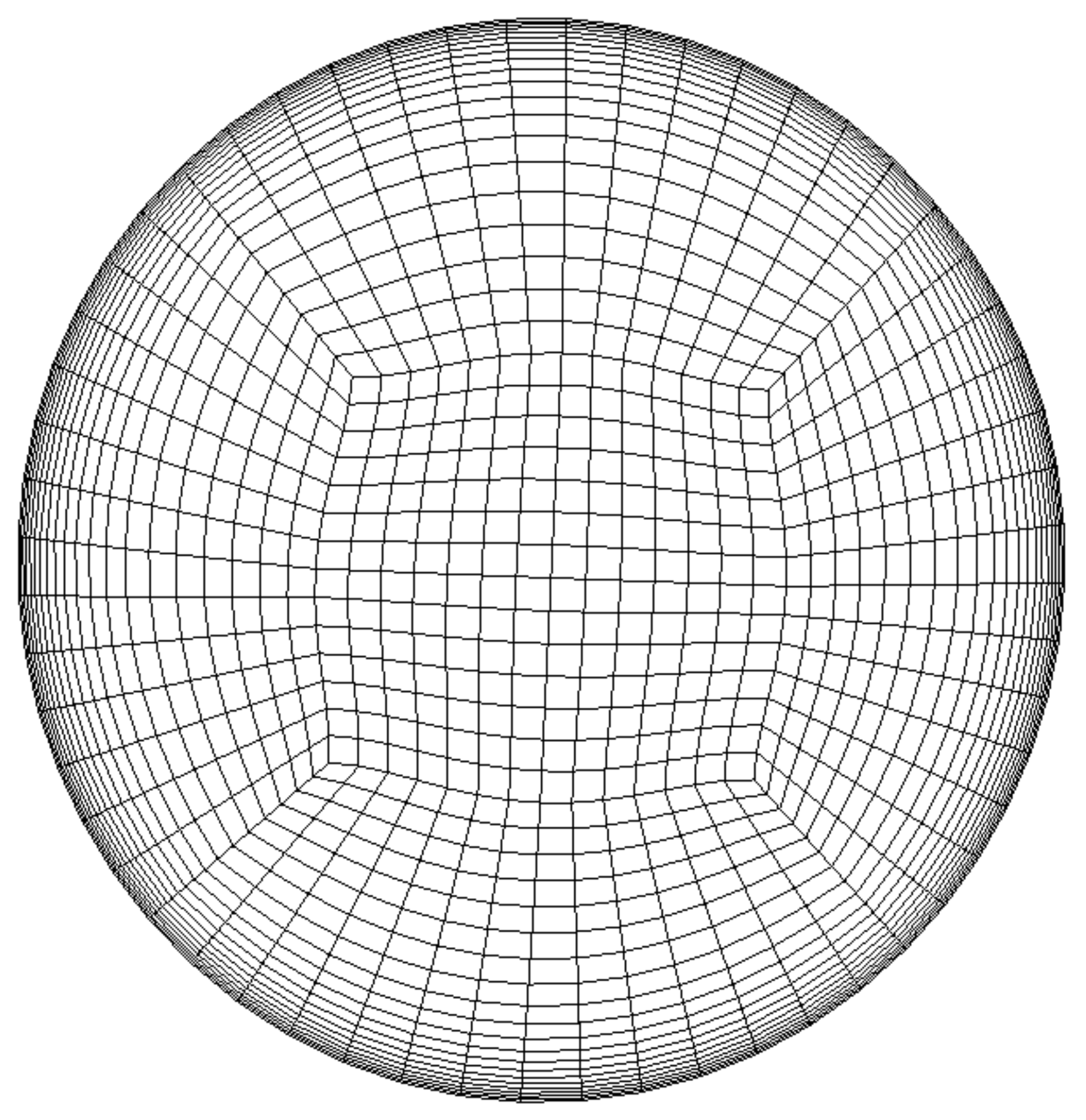
θ to the central plane, which is termed as the Half Impingement Angle (HIA). In the current study, the HIA considered are 15°, 22.5° and 30°. The mesh for the inclined pipe domain was maintained same as the mesh generated for single pipe simulation used for single jet study. The mesh in the outlet of pipe domain is as shown in
Figure 2. As with the previous study, the geometry was generated using SolidWorks, while the structured mesh was created using proprietary mesh generation code ICEM-CFD (version 16.2).
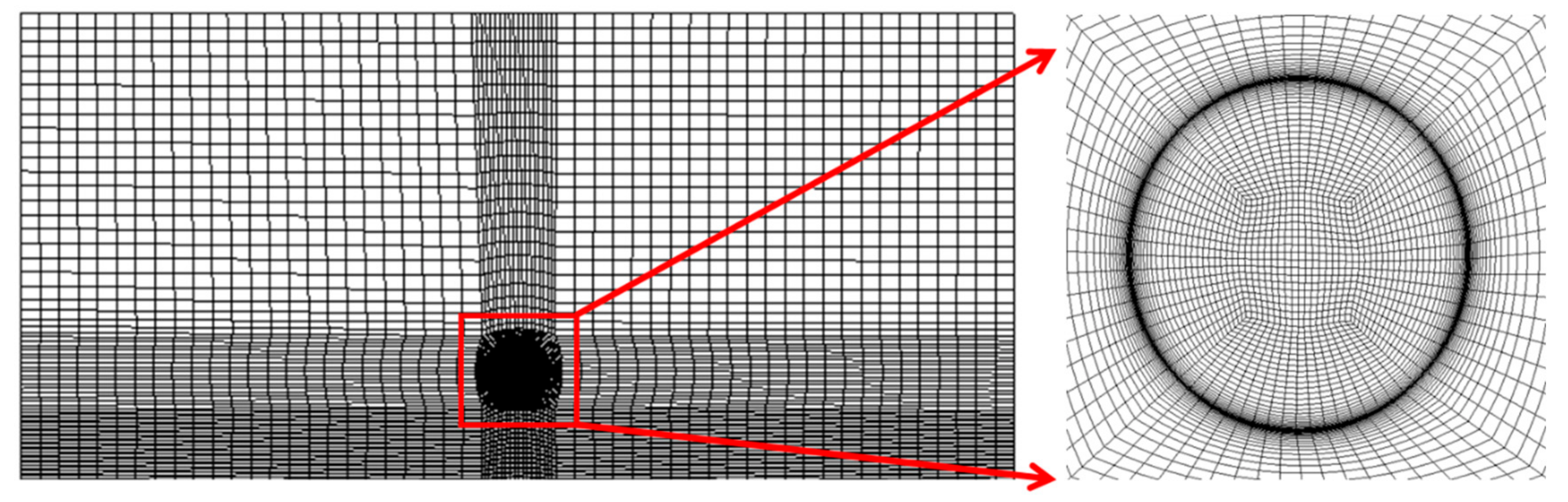
To ensure that accurate transfer of velocity and TKE data occurs from the pipe domain to jet domain, it was necessary to maintain 1-to-1 grid connectivity between the pipe domain and the domain downstream. Hence, the inlet of the jet domain (which acts as the exit of the pipe domain) was very finely meshed, to maintain 1-to-1 grid connectivity. The grid generated at the pipe exit/flow inlet section of jet domain is as shown in
Figure 3. The band of very fine mesh elements seen in the diagram corresponds to the wall surface mesh generated in the pipe domain. It is also worth noting that the area between the jets are meshed with fine mesh to ensure that the flow physics due to jet impingement is accurately captured.
The choice of turbulence model for the simulation of impinging jets is based on the work done earlier on single jets [
1]. Various turbulence models were analyzed for single jet flow conditions, and it was found that SST (Shear Stress Transport) k-ω model performed best for given range of Re under consideration. The details regarding SST k-ω model was discussed in [
1]. Separate velocity components were used in this study (u, v and w) instead of single velocity profile (as used in single jet study) to ensure that all the appropriate velocity vectors are transferred from the pipe domain into impinging jet domain.
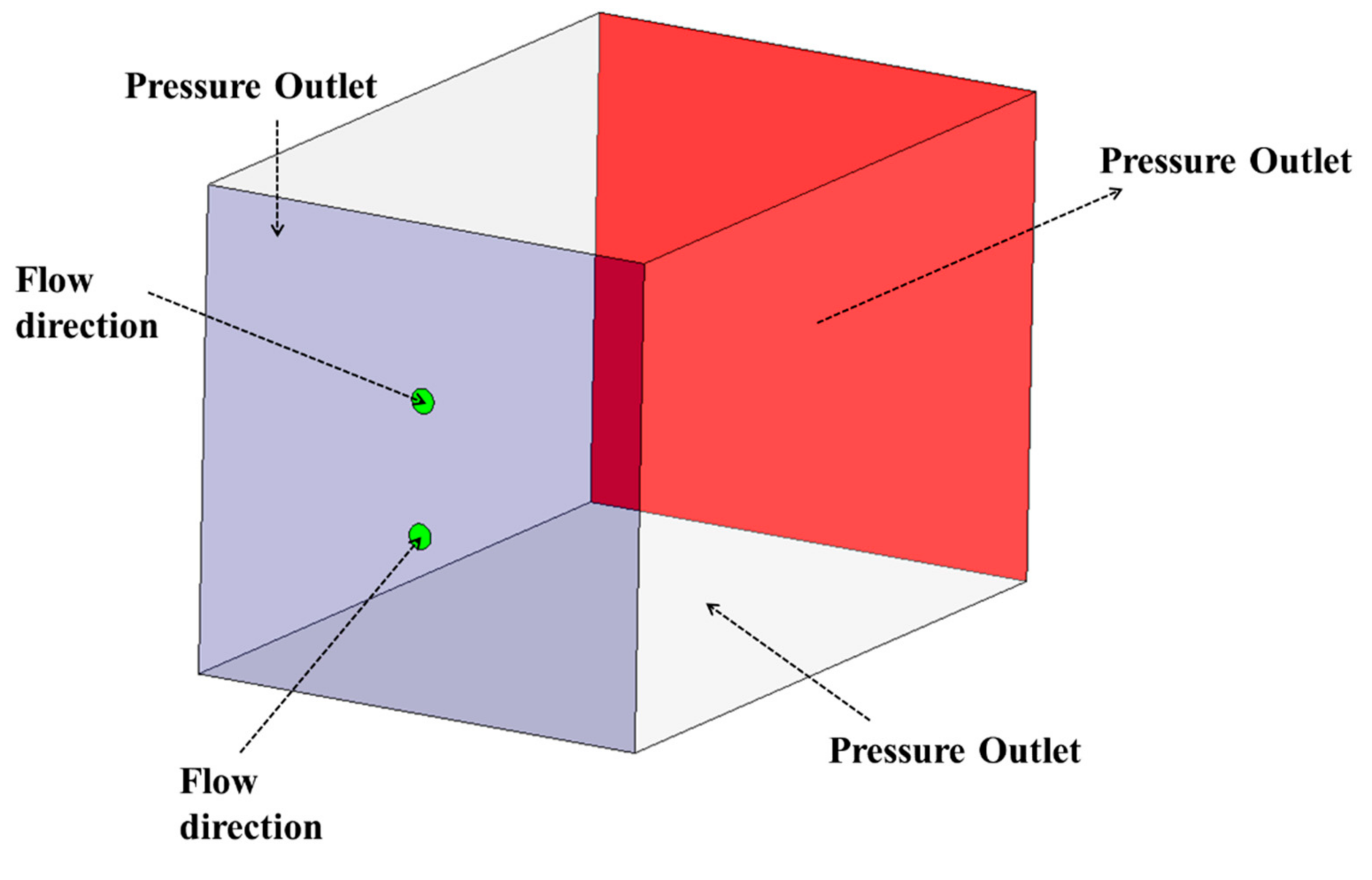
The schematic of boundary conditions used in the study is shown in
Figure 4. The green region denotes the inlet zone where pipe exit profile conditions are applied. The surface bounding the inlets (shown in blue) are modeled as pressure outlet condition. This denotes a condition of standard atmospheric pressure and temperature. This allows the flow to enter that surface in all directions since pressure outlet condition in Ansys Fluent allows for backward flow. The side surfaces (shown in white) and exit of the domain are also modeled as pressure outlet conditions, thereby replicating a fully open surface for the jet to grow.
The solver settings involved in this analysis is similar to that used in the case of single round jet study [
1]. SIMPLE algorithm was utilized for pressure–velocity coupling with the second-order Upwind scheme used for spatial discretization. A convergence criterion of 10
−6 was used for all the parameters to confirm that the solution had fully converged with minimal numerical error. Once the residuals for the convergence criterions were satisfied, the run was stopped, and the result files extracted to be post processed.
One of the major concerns involved in the meshing of impinging jet domain was that the same meshing philosophy used for single jet domain could not be used. In case of single jet, a single O-grid exiting the pipe domain was extruded into the jet domain, which radially expanded outwards; thereby capturing the relevant flow physics. In the case of impinging jets, there would be two such O-grids which need to interact with each other (at the point of impingement). However, it is not possible to generate two intersecting O-grids, as the meshes cannot overlap each other. This led us to the conclusion that the only possible solution is to keep the O-grid mesh straight out of the pipe domain parallel to the central plane, without any alignment towards the flow direction.
One of the major drawbacks of this approach is known to be False diffusion (FD). FD is defined as the artificial diffusion introduced by the numerical scheme when the flow has predefined obliquity to the grid lines and there exists a non-zero gradient of flow variables in the direction normal to flow. FD was extensively studied by de Vahl Davis and Mallinson [
14] who proposed an approximation expression to represent it in two-dimensional state as shown in equation below.
where
Γfalse represents false diffusion coefficient;
represents density; Δ
x and Δ
y represent corresponding mesh size in
x and
y direction;
U is the average flow velocity; and
θ stands for the angle between velocity vector and flow direction.
Patankar [
15] provided a very clear discussion of the issues related with FD in his book, highlighting that:
FD manifests only when a mesh obliquity exists with respect to velocity profile.
FD becomes maximum when sin 2θ is maximum, which is attained when θ becomes 45 degrees, i.e., flow direction is at 45° to the grid alignment.
FD can be reduced by mesh refinement, i.e., having smaller values for ∆x and ∆y, respectively.
FD cannot be removed by using Central difference scheme, since Central difference scheme are prone to produce unrealistic results at large grid Peclet number.
Focusing our attention to the problem of jet impingement, where predetermined obliquity between the velocity vector and grid direction exist, it was considered important to establish the effect of FD in the prediction of velocity profiles. A grid sensitivity study was established to identify the minimum number of mesh elements required to obtain a solution, which was not highly dependent on the quantity of grid nodes. It was concluded from that study that the final grid obtained was sufficiently fine to remove any artifacts of false diffusion.
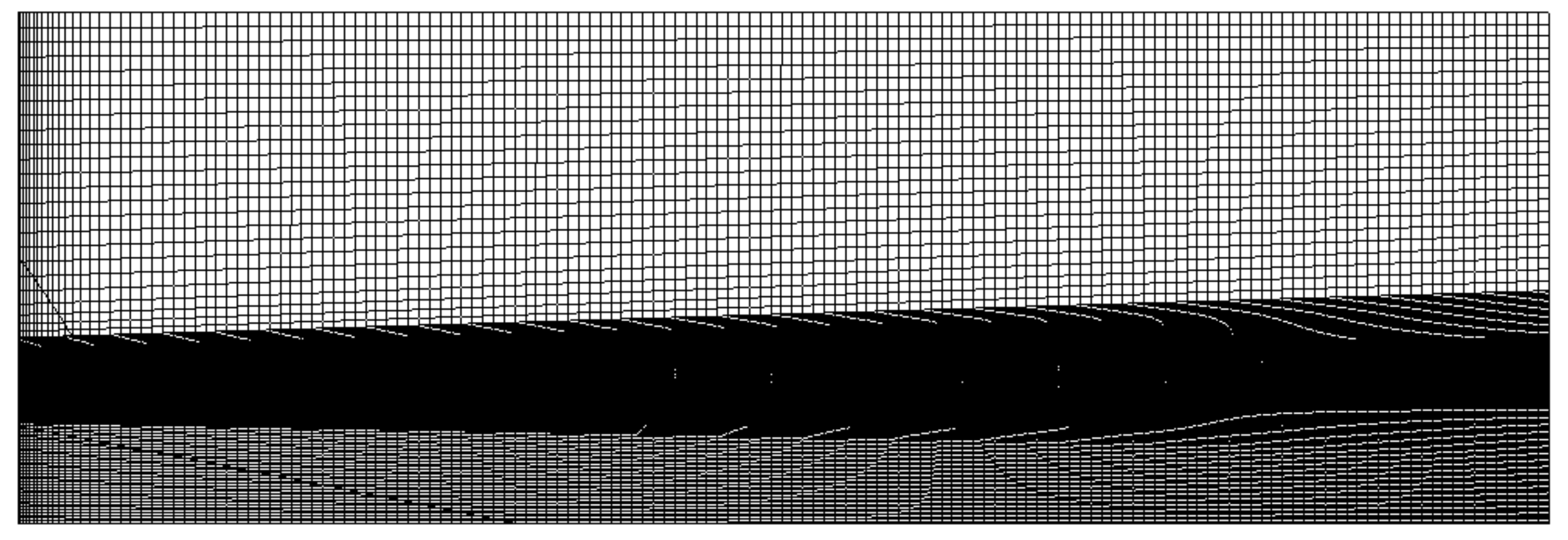
Another step considered to ensure that accurate flow results were obtained at minimal usage of computational resources was to use symmetry model instead of the full model. Since the boundary conditions are symmetric about the central plane, it can be assumed that the flow physics beyond interaction point is also symmetric in a steady state solution. Hence, for the current study, a symmetric model was used. The region corresponding to the zone of impingement is very finely meshed, as can be seen in
Figure 5. The node count generated for the symmetric mesh is close to 1.35 million.
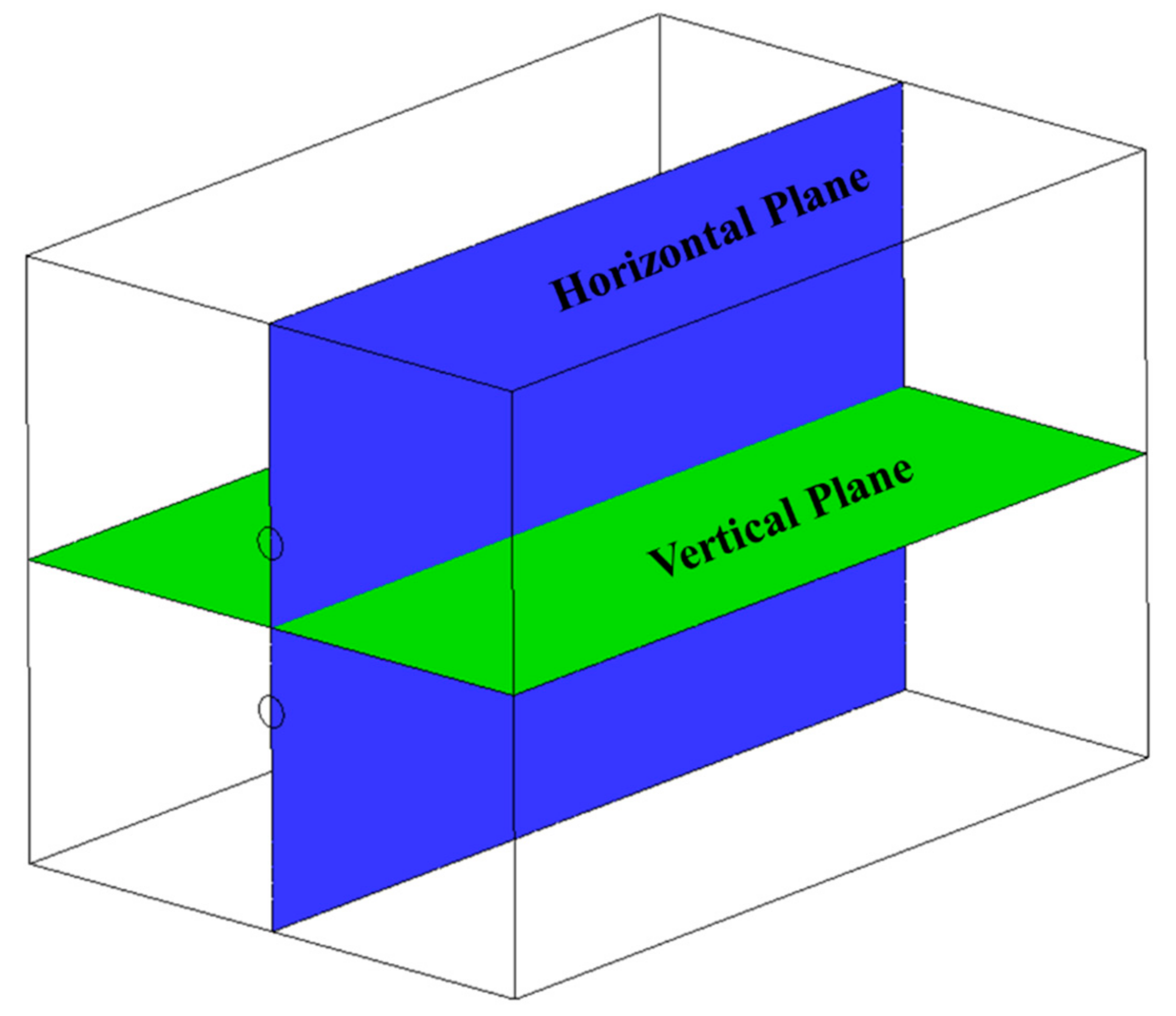
The planes where data were captured for the comparison are shown in
Figure 6. The naming convention used by Landers [
8] was followed in the current study. In the horizontal plane, the jet impingement occurs at angle 2
θ to one another. The impingement point lies on the intersection of horizontal and vertical plane, at a distance of 10.33 D from the pipe exit. The line formed at the intersection of horizontal and vertical plane is termed as the center line.
3. Grid Sensitivity Study
For every independent CFD analysis performed, it needs to be carefully verified that the solution was independent of the mesh count used by running the same simulation over various meshes and finding the smallest mesh where the target parameter does not change significantly with the change in mesh size.
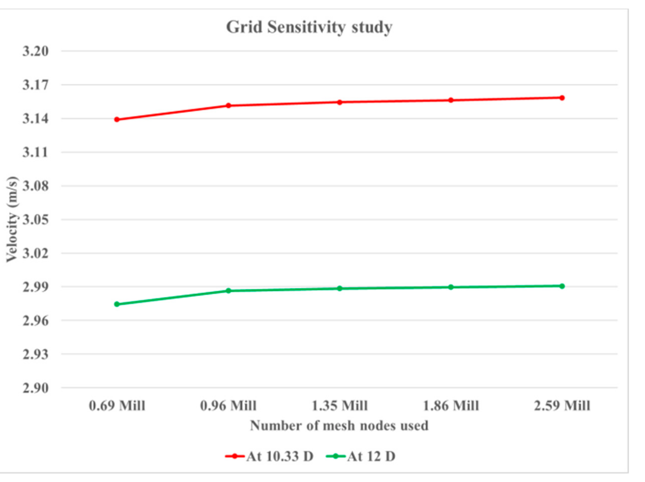
For the case of jet impingement study, the target parameter considered was velocity data along the center line at and beyond the impingement point. The velocity value at 10.33 D and 12 D along the center line was carefully noted for multiple meshes, and the general trend in variation was observed. The data were plotted systematically to identify the point of grid independence, as shown in
Figure 7.
In
Figure 7, it can be seen that the change in value of velocity is not significant when the mesh size is increase beyond 1.35 million nodes.
Table 1 shows the magnitude of variation of velocity value for other meshes with respect to 1.35 million node case (which was the reference case). Since the relative change in value is seen to be small, the mesh with node count of 1.35 million nodes was considered as the point of grid independence.
For all further studies, a grid size of 1.35 million nodes was used with symmetric model for jet impingement domain. Note that, in a study with different impingement angles, using the same grid size and meshing philosophy, changes in θ, Δx and Δy will occur, thereby changing the values of FD per case basis. However, the effect of FD is significantly less on velocity parameter at the current mesh size selected.
5. Conclusions
From the current study of jet impingement at multiple angle and constant Reynolds number, it was concluded that the SST k-ω model can predict velocity characteristics of impinging jets with reasonable accuracy. While generating the mesh for the current study, it was noted that false diffusion will play an important aspect in the analysis since the flow direction vectors is at an angle to the mesh elements. Hence, a grid sensitivity study was performed to generate a grid with enough nodes to reduce any artifacts of false diffusion. In addition, a symmetric domain was considered for the analysis.
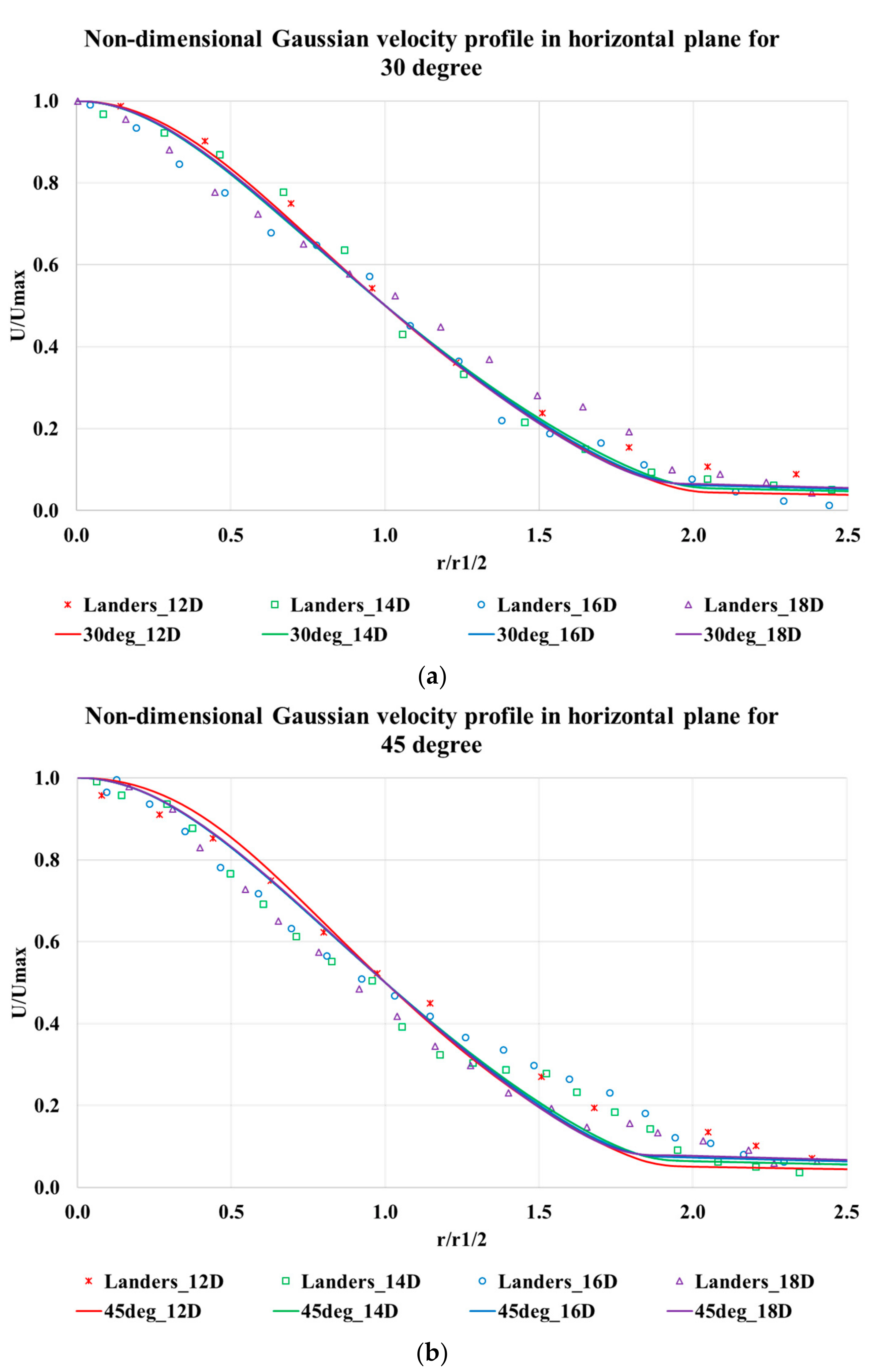
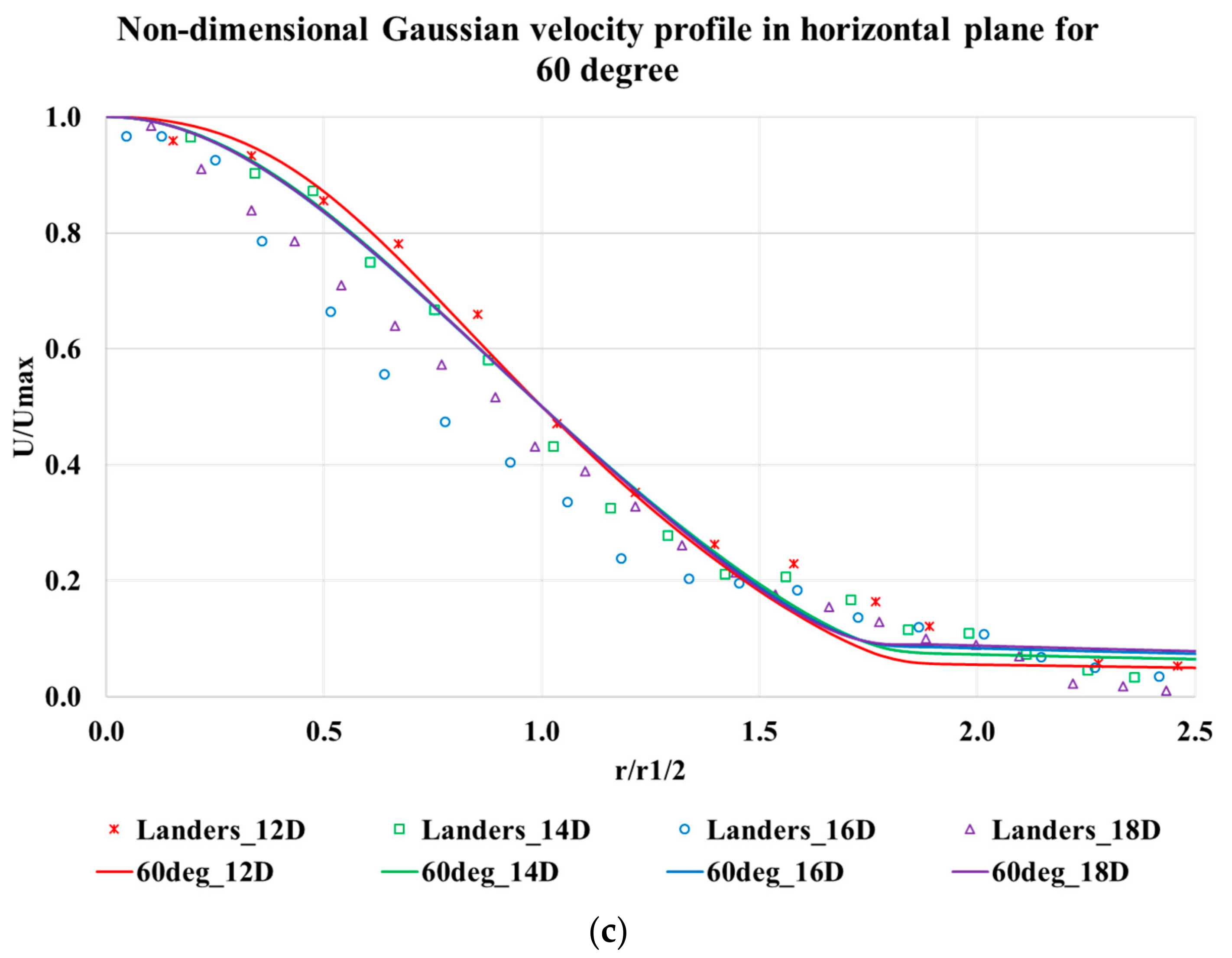
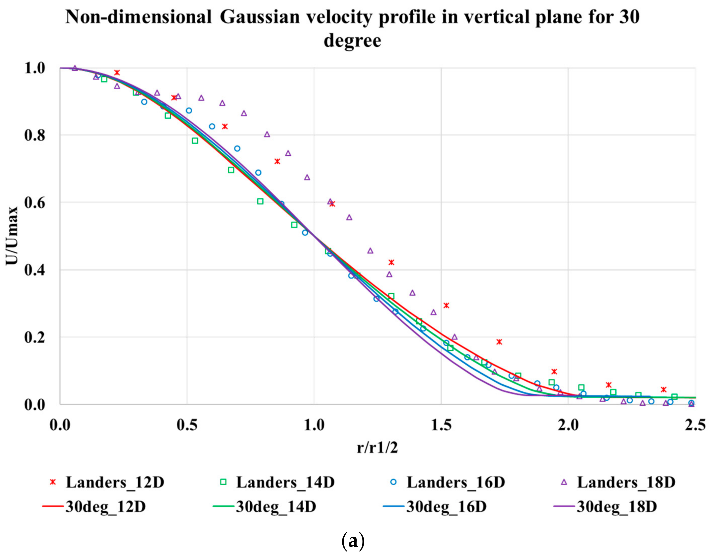
After obtaining a grid independent solution, the velocity data were compared with experimental results from Landers [
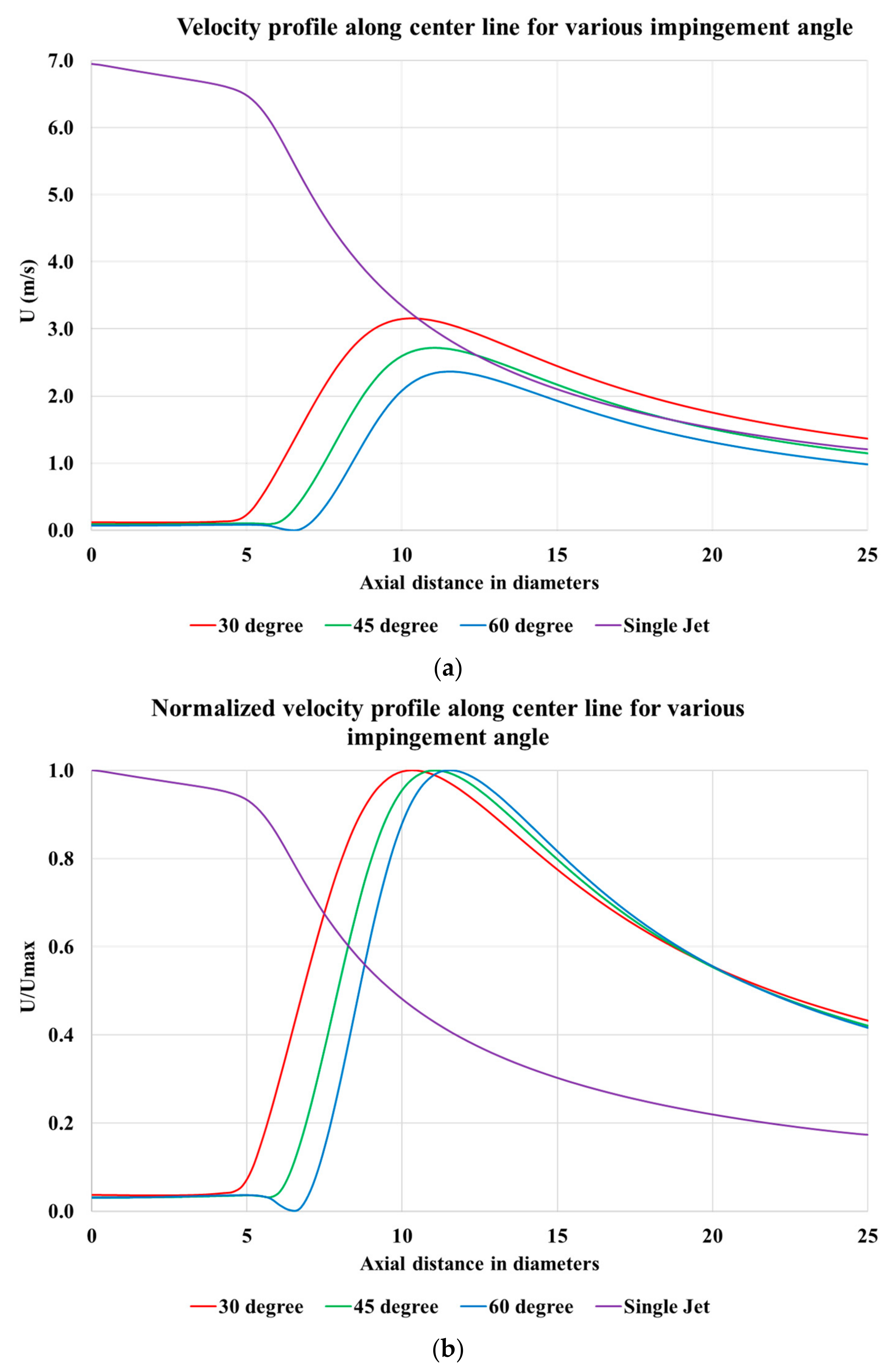
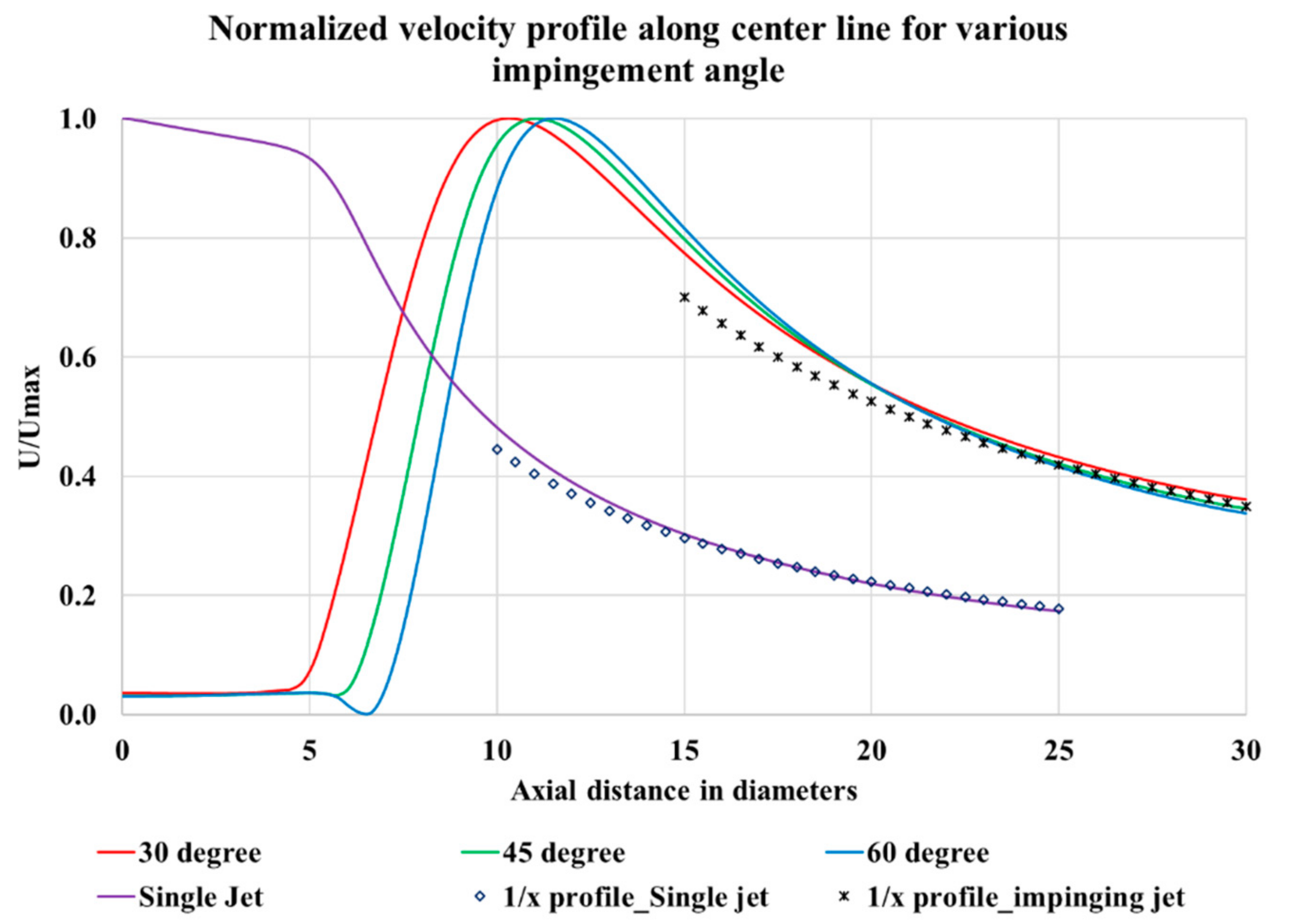
8] for validation. It was observed that a reasonable accuracy was observed between computational results and experimental data. Gaussian non-dimensionalized velocity profile also matched with experimental data for all impingement angles in both horizontal and vertical planes. It was also noted that the resultant jet formed from the jet interaction obeys 1/
x profile of jet center-line velocity decay suggesting that the combined flow takes on the character of a single circular jet.
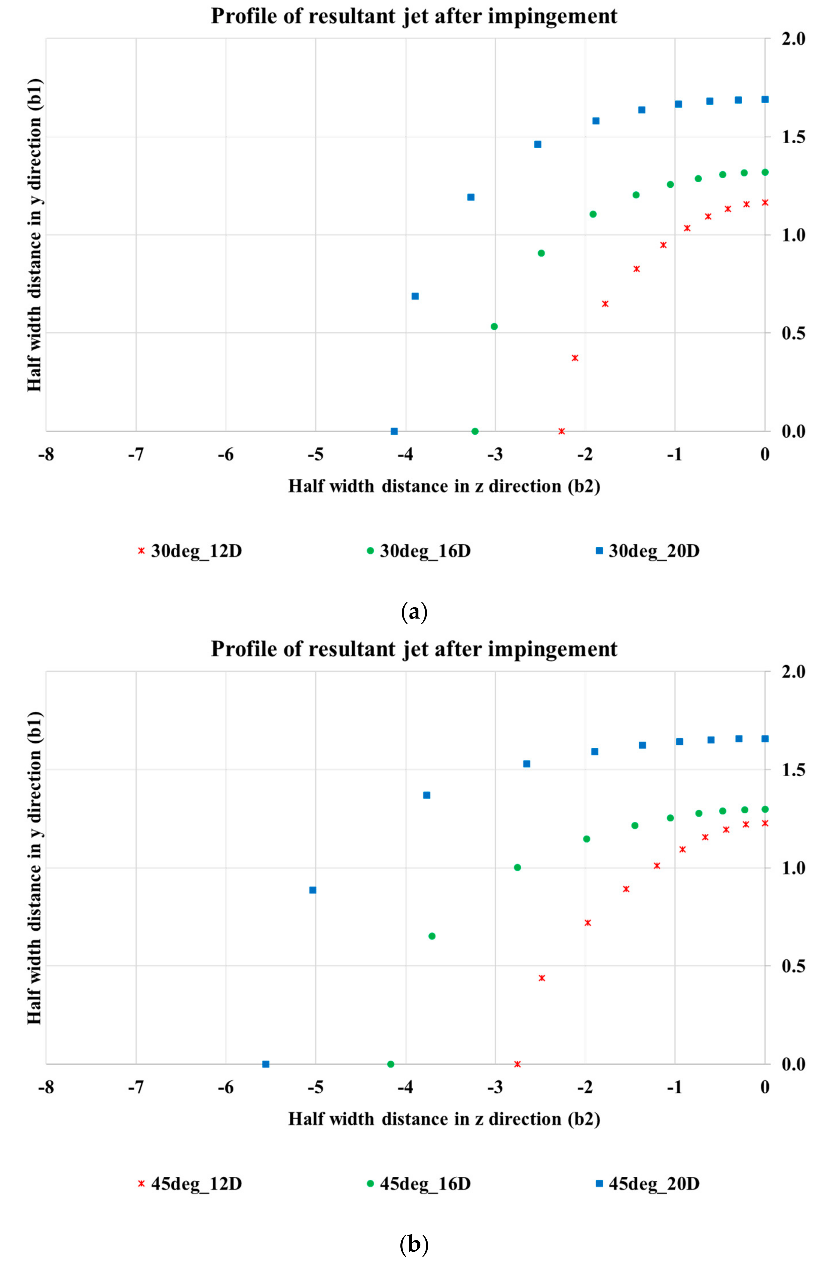
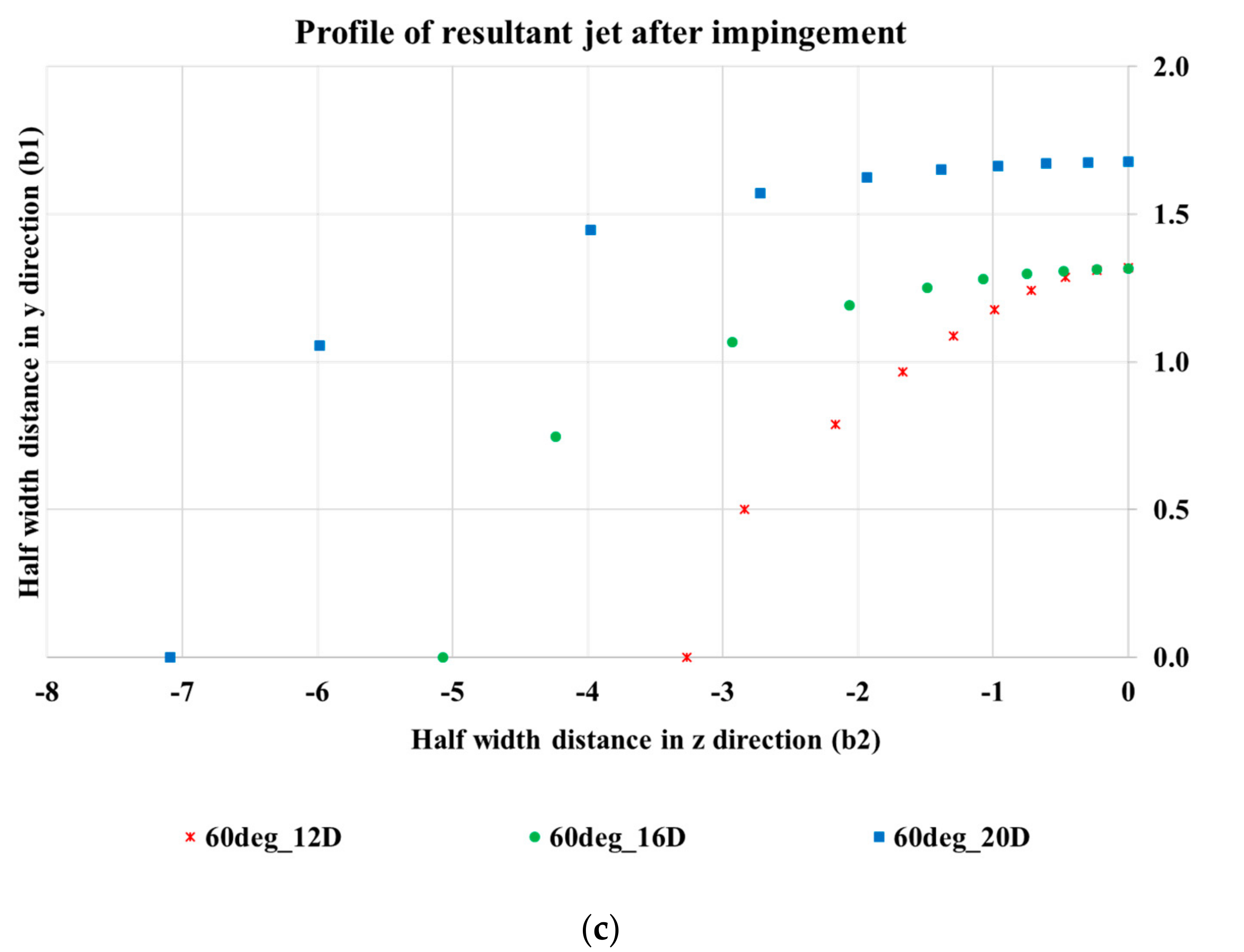
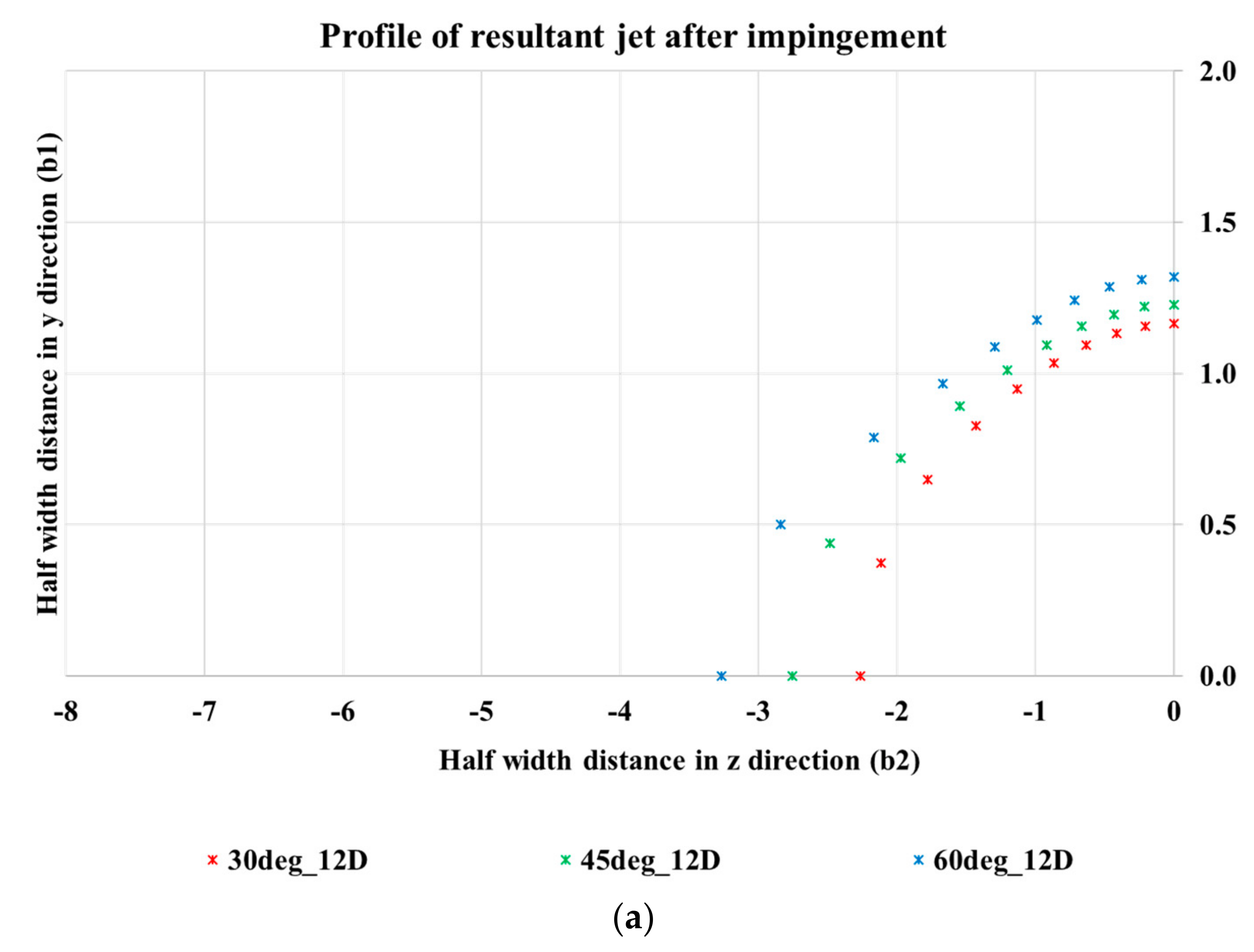
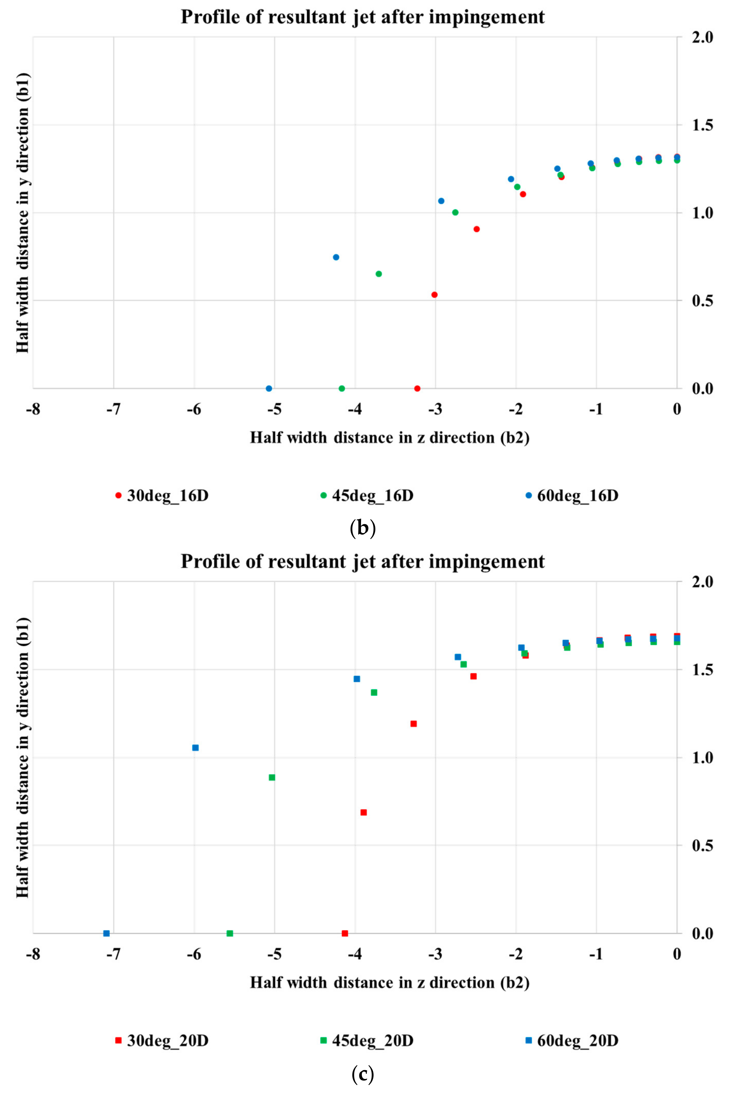
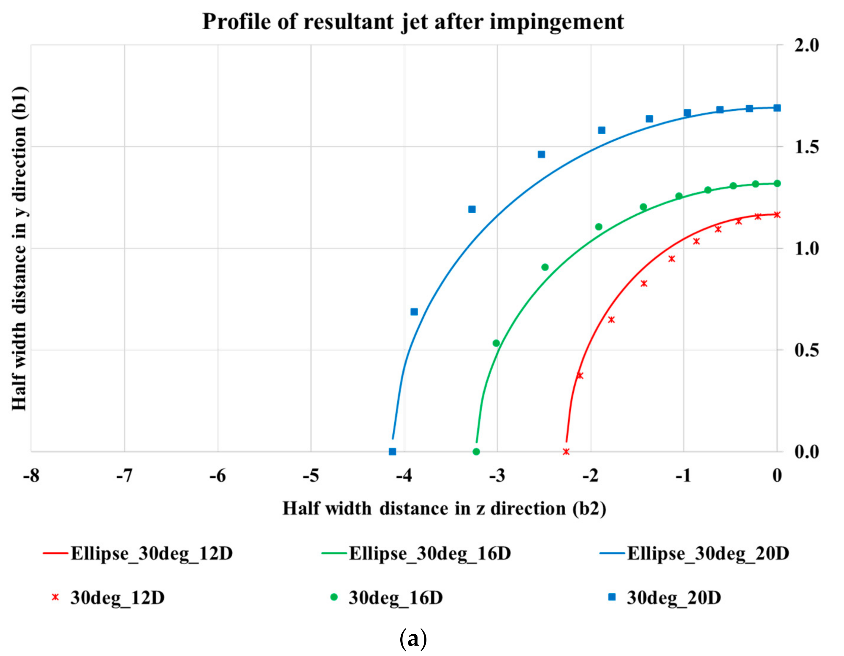
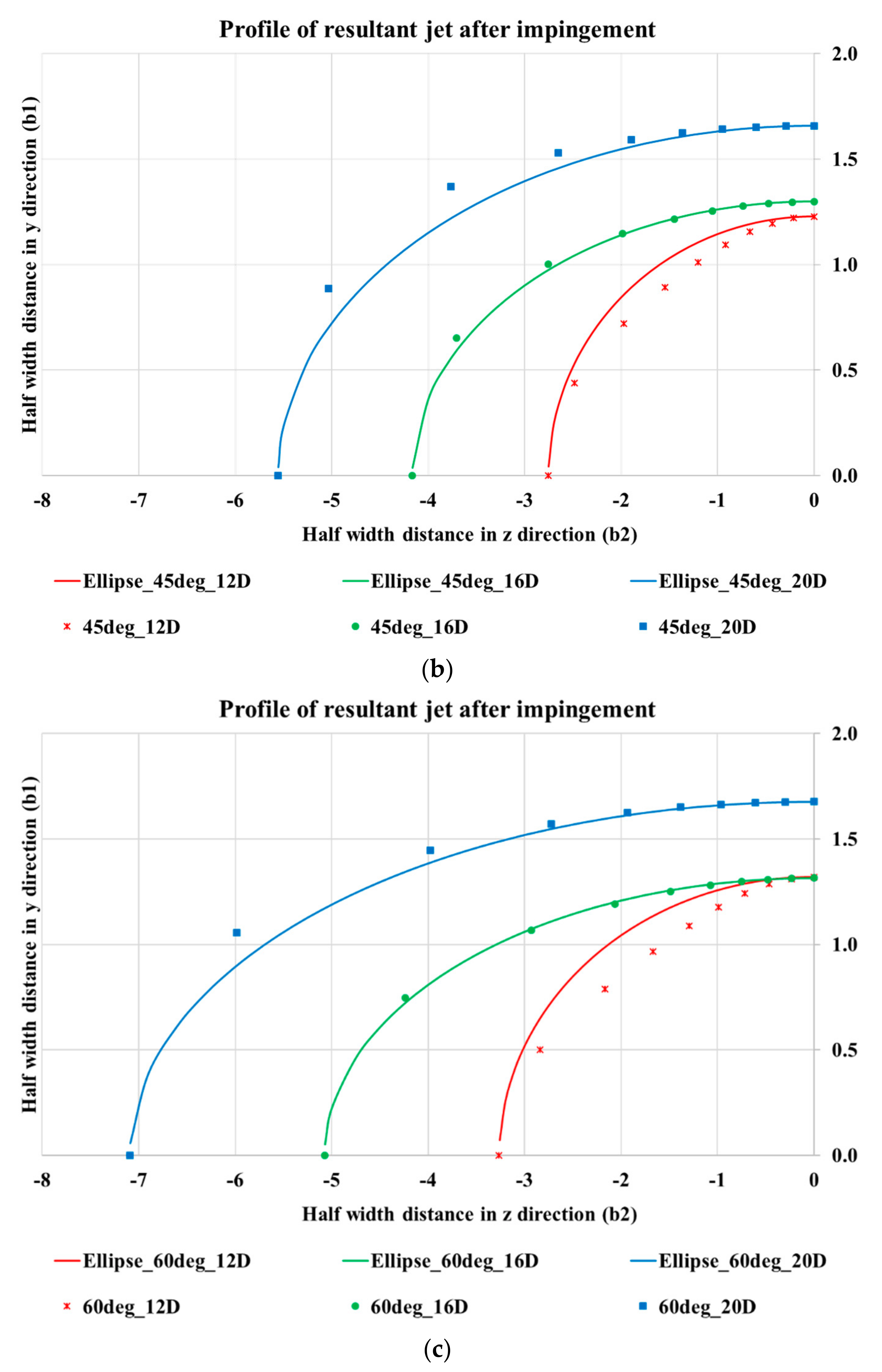
While establishing the profile of the resultant jet, it was found that the resultant jet follows an elliptical profile beyond impingement point. The growth of the jet along the plane perpendicular to the plane of the jet was observed to be significantly higher than the growth along the pipe plane. Hence, for any application where higher jet spread was required, the orientation of impinging jets is understood to play an important role. It is also observed that the growth profile in both the planes is dependent on the impingement angle, with jet spread along the vertical plane increasing with increase in impingement angle.


