
Review of Key Technologies of Rotary-Wing Mars UAVs for Mars Exploration

1
State Key Laboratory of Robotics and System, Harbin Institute of Technology, Harbin 150001, China
2
Center of Ultra-Precision Optoelectronic Instrumentation Engineering, Harbin Institute of Technology, Harbin 150001, China
3
Key Laboratory of Ultra-Precision Intelligent Instrumentation, Ministry of Industry Information Technology, Harbin 150080, China
4
College of Mechanical and Electrical Engineering, Harbin Engineering University, Harbin 150001, China
*
Author to whom correspondence should be addressed.
Inventions 2023, 8(6), 151; https://doi.org/10.3390/inventions8060151
Submission received: 1 November 2023
/
Revised: 27 November 2023
/
Accepted: 28 November 2023
/
Published: 29 November 2023
(This article belongs to the Special Issue Quadrotor UAV with Advanced Applications)
Abstract
:The sparse atmosphere on the surface of Mars provides the necessary flight conditions for Mars unmanned aerial vehicles (UAVs) to perform low-altitude flights. This work presents a comprehensive overview of key technologies in the development of Mars UAVs, with a specific focus on rotary-wing Mars UAVs. It summarizes prototypes of rotary-wing Mars UAVs developed by various global research institutions. It reviews essential technologies in rotary-wing Mars UAV research, including the Mars near-surface atmospheric environment, aerodynamic characteristics, and principles of low-pressure flight control. This work also summarizes various experimental setups and ground test results for rotary-wing Mars UAVs. Furthermore, it discusses the future development trends of rotary-wing Mars UAVs.
1. Introduction
Mars, which is adjacent to Earth in the solar system and shares similar physical dimensions and topography, provides a comprehensive record of the birth and evolution of planets in the past 4.5 billion years in the solar system [1,2]. Therefore, Mars exploration is important in expanding human habitation space and exploring the origin of life [3]. Over 40 Mars exploration missions have been implemented worldwide, with over 80% failing to achieve their intended objectives. Even Mars rovers that have successfully landed face the risks of becoming trapped in sand pits or experiencing mechanical failures [4]. In the 20th century, the former Soviet Union and the United States launched Mars probes but failed to complete their exploration missions [5]. In the 21st century, the United States once again launched the nuclear-powered Mars rover, Curiosity, and obtained comprehensive Mars environmental data. Researchers have discovered the presence of a tenuous atmosphere on Mars, which makes it possible to develop Mars UAVs to assist the Mars rovers in operating within the Martian atmosphere, attracting domestic and international attention from scholars [6,7].
Currently, the Mars UAVs developed abroad mainly include four types: floating balloons [8], fixed-wing UAVs [9], rotary-wing UAVs [10], and flapping-wing UAVs [11], as shown in Figure 1. The research on floating balloons started early; however, due to the difficulty in controlling them once released and their limited sensing capabilities, they did not receive extensive investigation. Fixed-wing UAVs, such as the ARES [9], can only perform a single flight after being released at high altitudes. Once their energy is depleted they will crash on the Martian surface and cannot be reused. Furthermore, due to the low image resolution, fixed-wing UAVs are not considered an optimal choice for a Mars UAV solution. Flapping-wing UAVs face significant limitations in their flight capabilities on Mars due to the low flight speed of their wings and the extremely low Reynolds numbers involved. These factors make it challenging for flapping-wing UAVs to achieve sustained flight on Mars. Hence, rotary-wing UAVs are positioned as aerial exploration platforms to assist Mars rovers [12,13], primarily for the following reasons: (1) the high flight speed of UAVs can greatly enhance the speed and efficiency of Mars exploration [14]; (2) the wide-ranging exploration capability of UAVs can expand the exploration range of Mars rovers, avoiding dangerous areas such as sand pits [15]; (3) the local exploration capability of UAVs can enable in-depth research in areas inaccessible to Mars rovers [16]; and (4) the precise landing and exploration capability of UAVs can assist Mars rovers in accomplishing multi-point sampling tasks [17].
The harsh Martian environment poses significant challenges for the study of Mars UAV technology. The Martian atmospheric density is only 1/70 that of Earth’s atmosphere, leading to significant effects on the aerodynamic characteristics of UAVs due to low-Reynolds-number flight conditions, including viscous effects and flow separation phenomena [18]. The presence of numerous steep circular mountains on the Martian surface necessitates UAVs to fly at suitable altitudes. The Martian surface is subject to unpredictable Martian winds and dust storms, with wind speeds ranging from 2 to 8 m/s and reaching up to 30 m/s at terrain boundaries [19], requiring UAVs to quickly adjust their attitudes to changing flight environments [20]. There are significant diurnal and seasonal temperature variations on Mars, with average temperatures of 213 K in summer and 153 K in winter [21]. The low temperature reduces the speed of sound on Mars to only 72% of that on Earth, resulting in UAV rotor blades operating at high Mach numbers and being susceptible to air compression effects and shock oscillations [22]. The Martian surface exhibits a diverse topography, with numerous raised circular ramparts, mountains, and canyons, necessitating Mars UAVs to perform takeoff and landing on a complex and ever-changing terrain [23]. A comparison of flight environments between Mars and Earth is shown in Table 1.
This work examines the characteristics and limitations of various UAV designs based on existing research on rotary-wing Mars UAVs. Additionally, it also provides a comprehensive summary of the aerodynamic simulation results, experimental research findings, flight control strategies, and system integration approaches for rotary-wing Mars UAVs. Building upon the current advancements in rotary-wing Mars UAV research, this study investigates the bottlenecks in the development of Mars UAVs.
2. Mars Near-Surface Atmospheric Environment
The Mars surface harbors a thin atmosphere, which enables the development of Mars spacecraft. However, the complex atmospheric conditions greatly impact the operation of Martian spacecraft [24]. Early Mars probes, such as Mars 1 and Mars 2, employed a low-altitude atmospheric density distribution model based on terrestrial ground test data with additional CO atmospheric corrections, rather than a genuine atmospheric model derived from actual Martian atmospheric data. Over the years, several Martian atmospheric models have been released internationally. The Committee on Space Research (COSPAR) established the COSPAR model in 1982, primarily based on data from the Mars probes [25]. The COSPAR model provides average, maximum, and minimum atmospheric density values for the Martian northern hemisphere during summer. The Mars Global Reference Atmospheric Model (Mars-GRAM), developed by NASA MSFC, simulates various factors affecting Martian atmospheric parameters [26] and can calculate average and perturbed atmospheric density values for any spatial location and time. This model is continuously updated, with the latest version being Mars-GRAM2010 [27]. The Martian Climate Database (MCD) model [28], a collaborative effort between the Laboratoire de Météorologie Dynamique (LMD), the University of Oxford, and the Andalusian Astrophysics Institute, offers the main atmospheric parameters for any given date and location under given extreme ultraviolet (EUV) radiation and dust storm scenarios. These parameters include atmospheric density, pressure, temperature, Martian dust density, state of Martian dust particles, horizontal and vertical wind speeds, CO ice cap thickness, atmospheric turbulence kinetic energy, and heat and solar radiation flux. This model is also subject to continuous updates, with the latest version being MCD5.2 [29]. All the aforementioned models are large-scale Martian atmospheric models. However, due to the increasing precision requirements for landing sites, large-scale models are no longer sufficient. Since 2000, the United States has successively released several medium-scale atmospheric models, such as MMM5 (Mesoscale Model Adapted to Mars) [30,31] and MRAMS (Martian Regional Atmospheric Modeling System) [32,33]. The atmospheric models used in foreign Mars missions are presented in Table 2 and Figure 2.
3. Development of Rotary-Wing Mars UAVs
Currently, in the field of rotary-wing Mars UAV research, numerous scholars have conducted extensive investigations into the following aspects: (i) the feasibility of rotary-wing Mars UAVs’ flight; (ii) the vertical-takeoff-and-landing (VTOL) capabilities of rotary-wing Mars UAVs; (iii) the development of prototypes for rotary-wing Mars UAVs. This section provides a summary of the state of research on rotary-wing Mars UAV technologies conducted by various research institutions [34,35], as depicted in Figure 3.
3.1. The University of Maryland
In the year 2000, the University of Maryland initiated a research project aimed at exploring the feasibility of rotary-wing Mars UAVs in the Martian atmospheric environment [36]. Subsequently, in 2001, they successfully engineered a rotary-wing Mars UAV named MICRO [37]. MICRO demonstrated the capability to hover in a simulated Martian atmospheric environment, equipped with an onboard camera for environmental reconnaissance. Furthermore, this UAV exhibited exceptional flight stability and robustness, enabling it to hover for 20 to 30 min. Notably, the figure of merit (FM) for this UAV reached 0.42. In 2003, the University of Maryland embarked on the design of a larger Mars UAV known as MARV, with a mass of approximately 50 kg. MARV could adjust its attitude in real-time while hovering [38]. In contrast to MICRO’s design paradigm, MARV featured non-viscous, incompressible blade design technology for its rotors, resulting in a low Mach number distribution over the rotor surfaces. This innovative approach ensured exceptional aerodynamic performance of the rotor system, allowing MARV to carry an effective payload of 10.8 kg, achieve a flight range of 25 km, a maximum endurance of 39 min, and maintain stable hovering for 1 min. Subsequently, in 2016, building upon experimental data obtained through rotor hovering tests based on the Ames Research Center (ARC), the University of Maryland conducted ground-based hover flight simulation experiments for rotary-wing Mars UAVs. These experiments factored in various parameters, such as Reynolds number, Mach number, and rotor structure, among others, to assess their impact on the FM of the rotor system. The final experimental results demonstrated that the selection of suitable airfoil profiles and an increase in the Reynolds number could elevate the FM of the rotor system from 0.34 to 0.6 [39], thereby enabling a 0.2 kg rotary-wing Mars UAV to achieve a flight duration of 12 to 13 min in the Martian atmospheric environment.
3.2. Stanford University
In the year 2000, sponsored by the National Aeronautics and Space Administration’s Advanced Concepts Research Institute (NIAC) in the United States, Stanford University researched a rotary-wing Mars UAV, Mesicopter [40]. The Mesicopter UAV had two generations. The prototype of the first-generation Mesicopter had a mass of 3 g and required an external power source for hover flight. In contrast, the prototype of the second-generation Mesicopter weighed 15 g and was powered by a battery. The battery of the second-generation Mesicopter weighed approximately 325 mg, while the control circuitry of the UAV weighed less than 1 g. Subsequently, Stanford University’s research focused on developing sensors, including core components such as magnetometers and gyroscopes, along with their system integration. Furthermore, Stanford University collaborated with Intel Corporation to develop optical fiber and radio-frequency communication equipment suitable for UAVs of this scale.
3.3. University of Surrey
In 2008, the University of Surrey proposed the utilization of rotary-wing UAVs to assist the Mars rover in carrying out certain Mars exploration tasks. They formulated a series of operational strategies for rotary-wing UAVs, enabling them to collaborate with the Mars rover to achieve multi-point sampling on the Martian surface. This was primarily achieved by harnessing the rotary-wing UAV’s hovering and low-speed flight capabilities, as well as its ability to take off and land multiple times, effectively reducing the risk of accidents for the Mars rover in complex and unknown terrain. Simultaneously, the precise landing of the rotary-wing UAV ensured the accuracy of collecting Martian soil samples from predetermined locations. Subsequently, the rotary-wing UAV transported the soil samples to the Mars rover, facilitating the rapid acquisition of Martian soil information [41]. In 2012, the University of Surrey introduced a tilt-rotor UAV named “Eye-On”. This unmanned aircraft, weighing 15 kg, with a rotor span of 1.4 m, boasted a cruising range of up to 100 km and a flight endurance of 38 min. It is noteworthy that Eye-On could independently perform vertical and horizontal flights, exhibiting commendable stability during horizontal flight and ensuring dynamic stability during the transition between vertical and horizontal flight modes [42]. Subsequently, in 2016, the University of Surrey unveiled a next-generation tilt-rotor UAV named “Y4TR”. Y4TR employs nonlinear sliding mode differential Riccati equation (SDRE) control for autonomous cruising. This UAV is equipped with a coaxially counter-rotating rotor system located within the central duct for vertical takeoff, while two sets of single rotors on either side of the UAV are employed for horizontal flight [43]. In comparison to Eye-On, Y4TR possesses a relatively larger mass and requires the use of three rotor systems to generate sufficient lift, resulting in higher energy consumption. Nevertheless, the flight process of Y4TR eliminates the need for complex adjustments between vertical and horizontal orientations.
3.4. Harbin Institute of Technology
Harbin Institute of Technology has extensively researched the key technologies of rotary-wing Mars UAVs. In 2021, they established a Martian Atmospheric Simulator (MAS) simulation system to perform ground experiments related to Martian atmospheric conditions. Additionally, they developed a series of test apparatus to assess the aerodynamic characteristics of rotary-wing systems, aiming to evaluate the flight performance of these systems [44]. Subsequently, they tested the lift-to-drag characteristics of two-dimensional wing profiles for Martian UAV rotary systems and optimized wing shapes suitable for the Martian environment [45]. Furthermore, in 2023, they refined a three-dimensional rotor system tailored for flight in the Martian atmospheric environment [46] and assessed the hovering performance of UAV rotor systems [47]. Moreover, Harbin Institute of Technology has also engaged in comprehensive conceptual design of Martian UAVs [48] and conducted extensive research on the dynamic characteristics and flight control methods of UAVs operating in the Martian environment [49,50].
3.5. Swiss Federal Institute of Technology in Zurich
In 2010, Swiss Federal Institute of Technology in Zurich (ETH Zurich) initiated the muFly project, intending to develop intelligent micro unmanned aerial vehicles (UAVs) while imposing stringent requirements on the overall size and mass of the UAV. ETH Zurich began by analyzing the mass distribution of the UAV and identified that the mass was primarily concentrated in the actuators (motors, servos) and electronic instruments. Conventional modular design approaches led to a relatively large mass for the UAV’s supporting structure. As a result, the first-generation muFly with a total mass of 95.84 g was developed [51]. Subsequently, ETH Zurich employed high-precision microsensors and structural units for system-level integration, leading to the assembly of integrated structural units, resulting in the compact and highly integrated second-generation muFly, with a total mass of 80.31 g. Throughout this process, there was no increase in the mass of electronic instruments, while the mass of the aircraft’s supporting structure decreased by approximately 77% [52]. Although this approach significantly reduced the overall mass of the UAV, it may have led to a decrease in the structural stability and reliability of the UAV. In 2016, the muFly team embarked on the development of a spherical-structured UAV named the spherical UAV. This UAV adopted the integrated design methodology of the muFly UAV to reduce the mass of the structural components while ensuring overall rigidity and reliability through the spherical structure [53]. This type of UAV exhibited excellent dynamic stability in the vertical direction but exhibited a certain degree of center-of-mass offset during flight.
3.6. The Ames Research Center
In 2001, NASA’s Ames Research Center (ARC) demonstrated the feasibility of utilizing the VTOL capability of rotary-wing UAVs to explore the rugged Martian surface. They proposed key technologies for rotary-wing UAVs, including lightweight structures, innovative propulsion systems, and autonomous flight. Predictions were made regarding the operational duration of UAVs in various weight ranges (10–50 km) [54]. In 2002, based on experimental results of four-blade independent rotors under simulated Martian atmospheric density conditions, the ARC analyzed and optimized the wing shape, chord length, and wingspan parameters of UAV rotors. This optimization improved the aerodynamic performance of the rotors under low-Reynolds-number conditions and led to the development of the TAMS series coaxial-rotor UAVs [55]. In 2005, the ARC explored the feasibility of UAVs with a maximum flight range of 500 kilometers and a maximum total mass of 2500 km [56]. Ultimately, they determined that releasing a small rotary-wing UAV through a Mars lander would be more meaningful to assist in exploration missions. This prediction considered conditions where the Reynolds number of UAV flight was less than 8 × 10 and the Mach number was less than 0.7 [57]. In the same year, the ARC collaborated with the Langley Research Center to develop a series of deployment strategies for UAVs on Mars. Extensive research was conducted on various aspects of Martian UAVs, including maximum lift, total mass, power source, mechanical efficiency, autonomous flight capability, reliability, and hover performance, among others [34].
3.7. The Jet Propulsion Laboratory
In 2004, the Jet Propulsion Laboratory (JPL) carried out an extensive investigation into the feasibility, aerodynamic characteristics, and hovering capabilities of rotary-wing Mars UAVs. This study involved a comparative analysis of flight principles, structural configurations, and adaptability across various types of Mars UAVs, with rotorcraft UAV-type Mars UAVs being recognized as a significant focus in Mars UAV research [58]. Subsequently, JPL collaborated with academic institutions such as the University of Maryland and the Georgia Institute of Technology to conduct in-depth research on rotorcraft UAV-type Mars UAV technology. The plan was to deploy the Mars UAV alongside Mars rovers in 2020 to aid in environmental exploration [59]. In 2015, the official website of JPL introduced the conceptual prototype of the Mars UAV [60]. This compact coaxial rotorcraft UAV-type Mars UAV possessed a mass of approximately 1 kg and a wingspan measuring 1.1 m. The lower section of the fuselage integrated systems and equipment including controllers, communication instruments, measurement and control devices, and power supplies within a storage compartment [61]. This integration significantly reduced the UAV’s mass, enabling it to perform flight maneuvers such as takeoff, hovering, maneuvering, and landing in a simulated Martian atmospheric environment. Currently, JPL is in the process of devising the control scheme for the UAV’s reconnaissance mission and conducting research on crucial parameters like payload capacity, endurance, and hover duration [62].
The conceptual prototype of the Mars UAV was unveiled on JPL’s official website in 2015. This small-scale coaxial-rotor Mars UAV can execute flight maneuvers such as takeoff, hovering, maneuvering, and landing within simulated Martian atmospheric conditions. In 2018, JPL, in collaboration with other research institutions, carried out thorough design and validation of the rotor system, main structure, avionics system, sensor payload, landing system, communication system, power system, and thermal control system for the rotary-wing Mars UAV of JPL. The intention was to launch it to Mars in 2020, alongside a rover [63]. In April 2019, the name "Ingenuity" was officially bestowed upon the Mars UAV in the United States [64,65]. The inaugural flight test of Ingenuity on Mars was successfully executed on 19 April 2021. This marked the first controlled flight ever achieved on another planet in human history, and it has been operational on Mars for one year [66]. Note that there are also open competitions for Mars UAVs, typically involving student groups, as detailed in [67], which are not elaborated upon within the scope of this work. The relevant parameters of the Mars unmanned aerial vehicles developed by various research institutions are shown in Table 3.
4. Progress in Aerodynamic Characteristics of Mars UAV Rotor System
The aerodynamic characteristics of rotary-wing Mars UAVs in the Martian atmosphere can be numerically simulated using finite element simulation methods. Based on finite element simulation, the distribution of the rotor surface flow field of rotary-wing Mars UAVs under given conditions can be obtained, allowing for the assessment of lift and drag characteristics of the rotor under different flight conditions. This approach facilitates the rapid acquisition of rotor characteristics suitable for the Martian environment, the description and analysis of phenomena such as laminar separation in low-pressure flow fields, and the determination of the optimal geometric shape of the two-dimensional wing and three-dimensional blade structure of the rotor system. This information is crucial for guiding the aerodynamic system design of rotary-wing Mars UAVs.
4.1. Research on Aerodynamic Characteristics of Rotor System
The rotor system functions as the primary lift source for rotary-wing Mars UAV flight, and its structural design constitutes a pivotal challenge in the realm of rotary-wing Mars UAV development. Due to the formidable challenges and high expenditures associated with the establishment of the atmospheric conditions requisite for rotor experimentation, encompassing parameters like gas pressure, density, temperature, and composition, early investigations pertaining to rotors predominantly relied upon finite element simulation techniques [68]. The finite element simulation technique, rooted in computational fluid dynamics (CFD) [69,70], presents advantages in terms of reduced research costs and expeditious computational speed. This enables the swift analysis of the lift-to-drag attributes of UAV airfoils, the aerodynamic characteristics of rotors, and the distribution of flow fields on rotor surfaces. Furthermore, it avails itself of providing theoretical elucidations for phenomena such as rotor stall, tip vortex compression, and shock oscillation [71].
Simulation outcomes concerning the airfoils of rotary-wing Mars UAVs divulge that, under conditions of low-Reynolds-number flight on Mars, the airfoil exerts a significant influence on the aerodynamic properties of the rotor. Unconventional curved airfoils, characterized by exceedingly slender thickness and pronounced camber, exhibit a noteworthy capacity to enhance the lift-to-drag ratio and mechanical efficiency of the rotor [72]. Nevertheless, the extreme thinness of the airfoil compromises the strength and rigidity of the rotor. Within the literature [73], multiple airfoil configurations underwent simulation to scrutinize their lift-to-drag attributes in the Martian milieu, revealing that the influence of the low Reynolds number on the airfoil lift-to-drag characteristics supersedes that of the Mach number. Refs. [74,75] reported that airfoils featuring a maximum camber position at 25% and a camber of 5% exhibit the highest lift-to-drag ratio in low-Reynolds-number settings. In addition, Ref. [76] conducted a comparative analysis of the aerodynamic characteristics of six low-Reynolds-number airfoils in the Martian environment, concluding that the E387 airfoil exhibits superior aerodynamic characteristics in the Martian atmospheric milieu. Furthermore, Refs. [77,78] ascertained that the structure of the E387 airfoil mitigates the laminar separation of the surface flow field, resulting in an augmented lift in low-pressure environments. Based on extensive CFD simulation results, employing machine learning for optimizing the airfoil of the rotary-wing Mars UAV can significantly enhance the lift-to-drag characteristics of its rotor system [79].
Simulation findings related to the rotors of rotary-wing Mars UAVs indicate that the precision of finite element simulations in the context of three-dimensional rotors lag behind that of two-dimensional airfoil simulations. Within Ref. [80], a fusion of simulation outcomes and rotor design theory corroborated the consistency in two-dimensional simulation outcomes, encompassing lift characteristics, power characteristics, and experimental findings. Nevertheless, the lower precision in the simulation of the transition region from laminar to turbulent flow rendered three-dimensional simulation outcomes less consistent with experimental results. Researchers harnessed the aerodynamic properties model of the ARES rotorcraft UAV, coupled with simulation outcomes of flight and attitude control models, for the structural design of UAV blades, thereby enhancing flight efficiency in low-pressure settings. Spedding leveraged non-viscous analysis theory to optimize the trailing-edge structure of the rotor, culminating in increased lift under conditions of low Reynolds number [81]. Additionally, Ref. [82] uncovered that flexible blade structures, fashioned using structural elements, adeptly adapt to intricate and ever-changing flow field environments. This attribute holds immense significance for rotary-wing Mars UAVs in adapting to the Martian atmospheric milieu. Despite the efficacy of finite element simulation techniques in reflecting the aerodynamic characteristics of rotors, continued enhancement of rotor simulations remains an imperative pursuit. The aerodynamic characteristics of rotor systems from various institutions are depicted in Figure 4. The aerodynamic characteristics of rotor systems for rotary-wing Mars UAVs are shown in Table 4.
4.2. Research on Rotor Surface Boundary Layer Separation Phenomenon
When rotary-wing Mars UAVs operate under low-Reynolds-number conditions, the viscous effects in the flow field cause an increase in the viscous forces to the same order as the shear forces [83,84]. Consequently, the pressure in the laminar boundary layer at the airfoil’s leading edge decreases. At the same time, the momentum increases, resulting in the cessation of laminar flow in the lower boundary layer and the occurrence of laminar separation [85]. Additionally, the viscous effects transition the flow field behind the rotary-wing Mars UAV from laminar to turbulent; the higher turbulent energy causes the flow field to reattach to the rotary-wing Mars UAV’s surface, forming separation bubbles [86,87]. Laminar separation leads to the rotary-wing Mars UAV stalling and low-frequency oscillations, severely impacting its aerodynamic performance [88]. The laminar separation phenomenon of early rotary-wing Mars UAVs was difficult to explain reasonably [89]; however, finite element simulation methods can be used to analyze laminar separation and separation bubble generation and dissipation [90], as well as predict the location of laminar separation and the extent of separation bubbles [91].
The laminar separation phenomenon results in a transitional flow field of laminar-to-turbulent flow on the surface of the rotary-wing Mars UAVs. Therefore, different models need to be employed to simulate the flow fields on different regions of the rotary-wing Mars UAVs’ surface. Additionally, accurate prediction of the formation and disappearance locations of separation bubbles is crucial for the accuracy of the simulations [76,92]. Koen et al. investigated the aerodynamic characteristics of rotary-wing Mars UAVs and analyzed the variation in flow field parameters around separation bubbles using an unsteady time-marching algorithm [93]. Their method allows for predicting the formation and disappearance locations of separation bubbles based on the flow field information around them. Montelpare et al. analyzed laminar boundary separation phenomena of rotary-wing Mars UAVs under low-Reynolds-number conditions using infrared thermography and proposed an experimental-based method for predicting separation bubbles [94]. Tatineni et al. studied the aerodynamic characteristics of various airfoil shapes under low-Reynolds-number conditions, analyzing the linear stability of laminar separation fields for different airfoil shapes. They found that the instability of the laminar separation bubble boundary layer in a rotary-wing Mars UAV’s flow field caused periodic shedding of vortices during the separation process, ultimately leading to the instability of the rotary-wing Mars UAV’s flow field [95]. The investigation of the rotor surface boundary layer separation phenomenon is depicted in Figure 5. And the boundary layer separation phenomenon of rotary-wing Mars UAVs is shown in Table 5.
5. Research on Control Methods of Rotary-Wing Mars UAVs
Given the harsh flight conditions on Mars, as well as the significant time delays in communication between Mars and Earth, coupled with the absence of GPS navigation, there exists an urgent imperative to address the technological challenges associated with the control of rotary-wing Mars UAVs and their compatibility with the Martian flight environment [96,97]. Furthermore, due to the spatial constraints of rotary-wing Mars UAVs, it is often necessary to employ control strategies specifically tailored to coaxial rotary-wing Mars UAVs. This presents distinctions from conventional quadcopter control methods [98,99]. This is essential to ensure the successful execution of UAV exploration missions on Mars. In the flight control of a rotary-wing Mars UAV, the thin Martian atmosphere results in a significantly smaller amplitude of lift variation with rotor speed compared to the variation in Earth’s environment. Consequently, the process of adjusting the flight attitude of a Mars UAV is slow [100]. Furthermore, phenomena such as Martian winds and dust storms severely impact the stability of Mars UAV flight, necessitating rapid adjustments to the changing environment to ensure flight safety [101,102]. In addition, Mars UAVs lack GPS navigation during flight and require autonomous navigation based on Mars rovers or Mars satellites serving as base stations [103]. Therefore, the control methods for Mars UAVs should consider the low-atmospheric-pressure aerodynamic characteristics and environmental disturbance resistance of the UAVs, building upon the control methods for Earth UAVs [104,105].
Currently, controlling rotary-wing Mars UAVs mainly involves adjusting the relative position of the tip path plane (TPP) and the UAV’s center of mass to achieve steering control and attitude adjustment [106]. Schafroth et al. [107] compared various steering control schemes for UAVs and validated the feasibility of a nonlinear control method based on model predictive control (MPC) [108] for adjusting the flight height and attitude of the UAV, leading to the development of the muFly UAV. To optimize the power system and steering system of the first-generation muFly UAV, the second-generation muFly employed control [109] and a covariance matrix adaptation–evolution strategy (CMA-ES) [110] to facilitate information interaction among the UAV’s components, and utilized an integration approach for mass optimization of the UAV’s functional modules. Furthermore, methods such as multi-objective task optimization and knowledge transfer [111,112] can enhance the autonomy and adaptability of rotary-wing Mars UAVs, thereby contributing to improved performance of UAVs in Mars exploration missions. In 2007, the University of Surrey proposed a control scheme for Mars spacecraft based on classical root trajectory analysis, frequency domain analysis, time domain analysis, and additional iterative experiments for the design of the attitude controller [96,113]. Although the University of Surrey linearized the nonlinear models and met the precision requirements for controller design, the controller failed to operate stably when integrating two separately designed controllers into a single system due to the lack of consideration of coupling effects. In 2018, Håvard and his team from the JPL presented an alternative control scheme for Mars spacecraft [114,115]. This scheme primarily considers two factors: (i) the ability of the spacecraft to maintain sufficient stability throughout the flight envelope, and (ii) the horizontal offset caused by gust disturbances within a certain range. To ensure adequate controllability under Martian conditions, Håvard and his team conducted extensive modeling and analysis of the dynamics of Mars spacecraft [116]. The control scheme developed by the Jet Propulsion Laboratory consists of four modules: the mode controller, navigation module, guidance module, and controller module. Due to the high level of uncertainty in modeling spacecraft dynamics under Martian-like conditions, relying solely on theoretical modeling is insufficient for reliable flight control design [117]. Therefore, the NASA JPL specifically conducted a “system identification” project to identify the actual dynamic characteristics of the developed prototype. In summary, significant progress has been made in the flight control of Mars UAVs, but issues such as slow response in attitude transformation, lack of GPS autonomous navigation, and rapid response to changing flow fields have yet to be effectively resolved. The investigation into control strategies for rotary-wing Mars UAVs is depicted in Figure 6. And the control methods for rotary-wing Mars UAVs are shown in Table 6.
6. Experiments on Hover Performance in Rotary-Wing Mars UAVs
The hover experiment involves placing a rotary-wing Mars UAV in a specific simulated environment and maintaining it in a hover flight state. This is to test the aerodynamic characteristics of the UAV’s rotor system and directly measure various aerodynamic parameters of the Martian UAV in a low-pressure experimental environment. This approach aims to assess the UAV’s hovering performance, thereby evaluating the feasibility of UAV flight in the Martian environment. This experimental method effectively provides accurate and reasonable boundary conditions for the numerical simulation of UAV fluid dynamics models and allows for a direct evaluation of UAV aerodynamic characteristics.
6.1. Mars Atmospheric Environment Simulation Setups
The aerodynamic characteristics of early Mars UAVs were primarily investigated through wind tunnel experiments [118]. Wind tunnel experiments enable the rapid acquisition of lift and drag coefficients for various two-dimensional wing profiles, aiding in the selection of wing geometries suitable for the Martian atmospheric environment [119]. However, wind tunnel experiments can only reflect the aerodynamic characteristics of individual cross-sections of the Mars UAV rotor blades. This limitation arises because the flow velocity along the rotor span direction of the Mars UAV exhibits a gradient, whereas in wind tunnel experiments, the flow velocity at each cross-section of the rotor system’s span direction remains the same [120]. Furthermore, in low-Reynolds-number environments, the drag coefficient of the wing profile is relatively small. Still, the wall effect significantly increases the drag coefficient of the wing profile in wind tunnel experiments. However, wind tunnel experiments can effectively replicate the influence of external environmental flow fields on the flight process of rotary-wing Mars UAVs, which is crucial for the assessment of the flight stability of rotary-wing Mars UAVs [118]. In the later stages, the Martian atmospheric simulation environment for Mars UAVs was primarily conducted through ground simulation using vacuum chambers or vacuum tanks. This involved the construction of a hover test platform inside a vacuum chamber to directly measure the rotor’s hover thrust and power consumption [121]. Since in the low-pressure environment of Mars, the lift generated by the rotor is much smaller than in Earth’s environment, the hover test apparatus used for Mars UAVs should possess higher measurement precision and resolution. Currently, Mars UAV hover test setups mainly comprise rotor lift test apparatus, drag test apparatus, torque test apparatus, and power test apparatus. The configurations of Mars atmospheric environment simulation setups used by different institutions are illustrated in Figure 7.
6.2. Experimental Setup for Hover Test of Rotary-Wing Mars UAVs
Due to the high-speed rotation of the rotor system of a rotary-wing Mars UAV in the Martian atmospheric environment, thrust is generated to balance its own weight [122]. However, the rate of change in parameters such as thrust, torque, and power associated with the aerodynamic characteristics of the rotor system is very low with respect to the rotor system’s rotational speed [96]. This necessitates that the hover test setup for the rotor system can directly measure thrust and power loss or indirectly measure thrust and power loss by measuring parameters such as rotational speed and displacement, while compensating for the interference of the measurement system’s weight on the results using counterweights and other methods, in order to enhance the accuracy and precision of the measurement equipment [123]. Therefore, the hover test setup needs to have a wide range of rotor speed adjustment capabilities, the ability to directly measure the aerodynamic parameters of the rotor system, and high measurement accuracy.
In order to evaluate the hovering performance of the Mars UAV rotor system, Kunz from Stanford University [124] designed a measurement apparatus for the lift and drag characteristics of the rotor system based on the principle of leverage. One end of the measurement apparatus is connected to the rotor system, while the other end is connected to a counterweight block and strain gauges. The measurement apparatus utilizes the counterweight method to directly measure the thrust of the rotor through strain gauges, and by horizontally mounting the rotor, it transforms the torque generated by the rotor into the corresponding stress on the strain gauges for measurement. However, the measurement apparatus is limited by the measurement accuracy of the strain gauges and the maximum size of the lever, and the friction of the bearings and the dynamic performance of the mechanical sensors will affect the accuracy of the measurement results. The use of a balance shaft instead of a lever can effectively improve the measurement accuracy, but it also increases the complexity of the measurement apparatus.
To improve the measurement accuracy of the thrust of the rotor system, Noriaki and colleagues from the University of Tokyo [125] designed a pendulum-style test apparatus for measuring the thrust of the UAV rotor. This apparatus indirectly measures the magnitude of rotor thrust by converting it into the swing angle of a pendulum and calculates the torque indirectly through motor power consumption. The angle accuracy of the pendulum is 0.01° (equivalent to a lift of 0.25 N). Noriaki and colleagues analyzed the influence of rotor structure on lift coefficient and torque coefficient, conducted feasibility studies on the composition and mass allocation of UAV systems and components, and validated the design scheme of a Mars UAV with a total mass of 100 g. The experimental configuration for conducting hover tests on rotary-wing Mars UAVs designed for Mars exploration is depicted in Figure 8.
6.3. Experiments on Hover Test of Rotary-Wing Mars UAVs
A study conducted by Young et al. [54] at NASA investigated the low-pressure hovering performance of a conceptual baseline rotor. It was found that with an installation angle of 15° and a rotational speed of 1200 r/min, a single rotor could lift a 10 kg object in a Mars-like atmospheric environment. Subsequently, the measured results of rotor lift coefficient and zero-lift angle of attack were compared with the theoretical calculations of the rotor. It was observed that there was good agreement between the two in the case of small angles of attack, while significant discrepancies were observed at large angles of attack. The limitations of this experiment include (1) the gas used for testing was air, whereas the primary component of the Martian atmosphere is CO; (2) it was challenging to simulate the environmental temperature of Mars in the vacuum chamber, resulting in the rotor’s Mach number being lower than it would be in a Martian environment; and (3) the vacuum chamber used for the experiment was occupied by other equipment, which caused interference with the airflow around the rotor.
John B. Brandt et al. from the University of Illinois at Urbana-Champaign designed a T-shaped test rig suitable for wind tunnel experiments [126]. The lift generated by the rotor is transmitted to the load sensor through the T-shaped lever. The required torque to overcome the rotor is directly measured by the torque sensor located behind the motor mount [127]. Noriaki et al. from the University of Tokyo designed a pendulum-type rotor lift testing apparatus, where the lift magnitude of the rotor is transformed into the swing angle of the pendulum for indirect measurement of lift. The sensitivity of the apparatus for lift measurement is 0.025 g [128].
In order to design a small rotary-wing Mars UAV for the “Mars 2020 Rover Mission”, the University of Maryland developed a testbed for evaluating the hovering characteristics of a rotary-wing Mars UAV [129]. Felipe et al. [130] initially arranged the UAV rotor characteristic measurement device inside a low-pressure tank for conducting hovering experiments and completed the design of a proof-of-concept prototype for a small Mars UAV. Subsequently, in collaboration with the NASA JPL, Robin et al. [39] accomplished the overall structural design of the rotary-wing Mars UAV. The proof-of-concept prototype underwent hover testing inside a vacuum chamber with a diameter and height of 0.91 m. The measured performance indicators such as low-pressure lift, power loss, and mechanical efficiency all met the design requirements, confirming the feasibility of the 1 kg Mars UAV design. Table 7 presents the relevant parameters of Mars UAV testbeds developed by different research institutions.
7. Conclusions and Future Perspectives
Rotary-wing Mars UAV technology is a critical area that demands immediate attention to expedite deep space exploration missions. Gaining a comprehensive understanding and proficient command of foreign advancements in Mars exploration technologies holds substantial significance for China’s forthcoming Mars exploration endeavors. This paper provides a comprehensive overview of the accomplishments achieved by various foreign research institutions in the realm of rotary-wing Mars UAV technology. Emphasis is placed on analyzing aerodynamic characteristics under conditions of low Reynolds numbers, UAV flight control and navigation, methods of system integration, and the current state of hover experiment research. The key technologies of the Mars rotary-wing UAVs discussed in this work are summarized as shown in Table 8.
The development of rotary-wing Mars UAVs differs significantly from their terrestrial counterparts in terms of both operational environment and flight conditions. Among the challenges encountered, the following bottleneck issues require immediate resolution: low-Reynolds-number aerodynamic shape design technology, control technology in low-vacuum microgravity environments, energy and power system design technology, and autonomous flight capabilities without reliance on GPS. Addressing these challenges forms the essential groundwork for harnessing rotary-wing UAVs to aid Mars rover exploration. In conclusion, the following recommendations are put forth:
(1) Selection of rotary-wing Mars UAVs and exploration methods based on mission characteristics. Due to the limitations of deep space probe carrying capacity, the development of low-altitude micro-sized rotary-wing Mars UAVs carried and released by Mars rovers has higher practical value for assisting Mars rover exploration and sampling. Referring to the relevant parameters of foreign rotary-wing Mars UAVs and China’s “Yutu” lunar rover, the structural dimensions of rotary-wing Mars UAVs should not exceed 200 × 200 × 200 mm, and the total mass of the UAV should not exceed 1 kg. For Mars rover’s close-range exploration tasks (less than 5 m), the rotary-wing UAV can adopt multiple position hover exploration and perform targeted landing and sampling analysis in valuable areas. For Mars rover’s long-distance exploration tasks (greater than 5 m), the rotary-wing UAV can adopt low-speed autonomous circumnavigation exploration. If the exploration area is determined to have further value, it can guide the Mars rover to approach and complete close-range exploration and sampling.
(2) Study of structural design for rotary-wing UAVs in the Martian environment. Low-altitude flight of rotary-wing Mars UAVs is characterized by a special low-Reynolds-number and high-Mach-number environment different from atmospheric flight on Earth. Regarding the design of the UAV’s airfoil, special attention should be given to unconventional curved airfoil profiles with extremely thin thickness and large airfoil curvature (e.g., E387 airfoil), and the special airfoil structures that can weaken the formation of laminar bubbles on the airfoil’s trailing surface in low-Reynolds-number flow fields. Regarding the design of the UAV’s rotor, emphasis should be placed on rotors with a large chord length and wingspan (e.g., Ingenuity UAV rotor). Based on many hover performance experimental results, the aerodynamic behavior of the rotary-wing UAV rotor system under different dynamic parameters such as angle of attack and rotor speed should be observed. To adapt to the narrow cargo space of Mars rovers, inflatable deployable wings, tail wings, and other structures can be used for the rotary-wing UAV’s external structure.
(3) System integration based on MEMS technology. Highly integrated rotary-wing Mars UAVs play a crucial role in enhancing the payload capacity and flight endurance of UAVs. Considering the limited payload capacity of Mars rovers, the scale of auxiliary UAV systems for Mars rovers should not be excessive. Microelectromechanical systems (MEMS) technology, designed for lightweight and small-scale Earth UAVs, can significantly reduce the mass of rotary-wing Mars UAVs. Currently, foreign scholars have adopted methods of integrating and assembling electronic components with the airframe structure, greatly reducing the mass of rotary-wing Mars UAVs. While this approach significantly reduces the mass of the UAV’s structural components, it may weaken the stiffness and reliability of the rotary-wing Mars UAV’s structure. To achieve both high integration and structural reliability, integrating the electronic components of the rotary-wing Mars UAV with a structurally stable airframe (e.g., a spherical UAV) represents a feasible unconventional structural approach for rotary-wing Mars UAVs.
(4) Development of autonomous UAV control methods. In Mars exploration missions, the adoption of autonomous feedback control methods with a certain level of autonomy will greatly enhance the UAV’s adaptability to the uncertain flight environment on Mars. Currently, foreign researchers primarily employ nonlinear control methods (e.g., control methods) for autonomous navigation and flight of rotary-wing Mars UAVs, but these methods are still in the testing phase and are not suitable for the high reliability requirements of deep space exploration. Additionally, rotary-wing Mars UAVs cannot rely on GPS navigation and positioning, and traditional positioning devices such as magnetometers struggle to operate in Mars’s weak magnetic field environment. Utilizing the Mars rover as a base station for wireless positioning of rotary-wing Mars UAVs or using lightweight cable connections for communication, or relying on “inertial navigation sensors + external sensor” combinations, can serve as suitable options for rotary-wing Mars UAV positioning in Mars’s unique conditions.
Author Contributions
Conceptualization, P.Z. and H.L.; methodology, P.Z. and R.L.; validation, P.Z., P.W. and X.G.; investigation, P.Z., R.L., P.W. and H.L.; writing, P.Z., P.W. and X.G.; supervision, Z.D.; funding acquisition, P.Z. and Z.D. All authors have read and agreed to the published version of the manuscript.
Funding
This research was funded by the National Natural Science Foundation of China (52105547), the China Postdoctoral Science Foundation (2021M700995), and the Natural Science Foundation of Heilongjiang Province (LBH-Z21063).
Institutional Review Board Statement
Not applicable.
Informed Consent Statement
Not applicable.
Data Availability Statement
Data will be made available on request.
Acknowledgments
We would like to express our gratitude to Academician Zongquan Deng, Qiquan Quan, and Dewei Tang from Aerospace Mechanism Testing laboratory, HIT for their guidance and support in the field of Mars UAV technology.
Conflicts of Interest
The authors declare no conflict of interest.
References
- Li, C.; Zhang, R.; Yu, D.; Dong, G.; Liu, J.; Geng, Y.; Sun, Z.; Yan, W.; Ren, X.; Su, Y.; et al. China’s Mars exploration mission and science investigation. Space Sci. Rev. 2021, 217, 57. [Google Scholar] [CrossRef]
- Zou, Y.; Zhu, Y.; Bai, Y.; Wang, L.; Jia, Y.; Shen, W.; Fan, Y.; Liu, Y.; Wang, C.; Zhang, A.; et al. Scientific objectives and payloads of Tianwen-1, China’s first Mars exploration mission. Adv. Space Res. 2021, 67, 812–823. [Google Scholar] [CrossRef]
- Ye, P.J.; Peng, J. Deep space exploration and its prospect in China. Eng. Sci. 2006, 8, 13–18. [Google Scholar]
- Wright, M.; Edquist, K.; Tang, C.; Hollis, B.; Krasa, P.; Campbell, C. A review of aerothermal modeling for Mars entry missions. In Proceedings of the 48th AIAA Aerospace Sciences Meeting including the New Horizons Forum and Aerospace Exposition, Orlando, FL, USA, 4–7 January 2010; p. 443. [Google Scholar]
- Reynier, P. Survey of aerodynamics and aerothermodynamics efforts carried out in the frame of Mars exploration projects. Prog. Aerosp. Sci. 2014, 70, 1–27. [Google Scholar] [CrossRef]
- Ouyang, Z.; Xiao, F. Major scientific issues involved in Mars exploration. Spacecr. Environ. Eng. 2011, 28, 205–217. [Google Scholar]
- Wan, W.; Wang, C.; Li, C.; Wei, Y. China’s first mission to Mars. Nat. Astron. 2020, 4, 721. [Google Scholar] [CrossRef]
- Hall, J.; Pauken, M.; Kerzhanovich, V.; Walsh, G.; Fairbrother, D.; Shreves, C.; Lachenmeier, T. Flight test results for aerially deployed Mars balloons. In Proceedings of the AIAA Balloon Systems Conference, Virtual, 21–24 May 2007; p. 2626. [Google Scholar]
- Braun, R.D.; Wright, H.S.; Croom, M.A.; Levine, J.S.; Spencer, D.A. Design of the ARES Mars airplane and mission architecture. J. Spacecr. Rocket. 2006, 43, 1026–1034. [Google Scholar] [CrossRef]
- Young, L.A.; Aiken, E.W.; Derby, M.; Johnson, J.; Navarrete, J.; Klem, J.; Demblewski, R.; Andrews, J.; Torres, R. Engineering Studies into Vertical Lift Planetary Aerial Vehicles; Technical Report; National Aeronautics and Space Administration Moffett Field CA Rotorcraft: Santa Clara County, CA, USA, 2002.
- Bar-Cohen, Y.; Colozza, A.; Badescu, M.; Sherrit, S.; Bao, X. Biomimetic flying swarm of entomopters for Mars extreme terrain science investigations. Concepts Approaches Mars Explor. 2012, 1679, 4075. [Google Scholar]
- Shi, J.; Zhang, Z.; Liu, Z.; Wang, Y. An analysis of results of the Martian environment exploration. Prog. Geophys. 1997, 12, 98–108. [Google Scholar]
- Cheng, X.; Li, J.; Wang, Q. Aerodynamic force characteristics of Mars entry vehicles. J. Astronaut. 2010, 31, 967–972. [Google Scholar]
- Patel, A.; Karlsson, S.; Lindqvist, B.; Kanellakis, C.; Agha-Mohammadi, A.A.; Nikolakopoulos, G. Towards energy efficient autonomous exploration of Mars lava tube with a Martian coaxial quadrotor. Adv. Space Res. 2023, 71, 3837–3854. [Google Scholar] [CrossRef]
- Witze, A. Mars helicopter kicks up dust cloud—and unexpected science. Nature 2021, 594, 484. [Google Scholar] [CrossRef]
- Folsom, L.; Ono, M.; Otsu, K.; Park, H. Scalable information-theoretic path planning for a rover-helicopter team in uncertain environments. Int. J. Adv. Robot. Syst. 2021, 18, 1729881421999587. [Google Scholar] [CrossRef]
- Withrow, S.; Johnson, W.; Young, L.A.; Cummings, H.; Balaram, J.; Tzanetos, T. An advanced Mars helicopter design. In Proceedings of the ASCEND 2020, Virtual, 16–18 November 2020; p. 4028. [Google Scholar]
- Geminale, A.; Formisano, V.; Sindoni, G. Mapping methane in Martian atmosphere with PFS-MEX data. Planet. Space Sci. 2011, 59, 137–148. [Google Scholar] [CrossRef]
- Ouyang, Z.; Xiao, F. The Mars and its environment. Spacecr. Environ. Eng. 2012, 29, 591–601. [Google Scholar]
- Sharp, R.P. Mars: Troughed terrain. J. Geophys. Res. 1973, 78, 4063–4072. [Google Scholar] [CrossRef]
- Kass, D.; Kleinböhl, A.; McCleese, D.; Schofield, J.; Smith, M. Interannual similarity in the Martian atmosphere during the dust storm season. Geophys. Res. Lett. 2016, 43, 6111–6118. [Google Scholar] [CrossRef]
- Dong, C.; Lee, Y.; Ma, Y.; Lingam, M.; Bougher, S.; Luhmann, J.; Curry, S.; Toth, G.; Nagy, A.; Tenishev, V.; et al. Modeling Martian atmospheric losses over time: Implications for exoplanetary climate evolution and habitability. Astrophys. J. Lett. 2018, 859, L14. [Google Scholar] [CrossRef]
- Hall, D.W.; Parks, R.W. On the development of airborne science platforms for Martian exploration. In Proceedings of the Foundation of the Mars Society, Boulder, CO, USA, 3–16 August 1998. [Google Scholar]
- Forget, F.; Wordsworth, R.; Millour, E.; Madeleine, J.B.; Kerber, L.; Leconte, J.; Marcq, E.; Haberle, R.M. 3D modelling of the early martian climate under a denser CO2 atmosphere: Temperatures and CO2 ice clouds. Icarus 2013, 222, 81–99. [Google Scholar] [CrossRef]
- Kminek, G.; Rummel, J.; Cockell, C.; Atlas, R.; Barlow, N.; Beaty, D.; Boynton, W.; Carr, M.; Clifford, S.; Conley, C.; et al. Report of the COSPAR Mars special regions colloquium. Adv. Space Res. 2010, 46, 811–829. [Google Scholar] [CrossRef]
- Justh, H.; Justus, C.; Ramey, H. Mars-GRAM 2010: Improving the precision of Mars-GRAM. In Proceedings of the Fourth International Workshop on the Mars Atmosphere: Modelling and Observations, Paris, France, 8–11 February 2011. [Google Scholar]
- Justus, C.; Duvall, A.; Keller, V.W. Validation of Mars global reference atmospheric model (Mars-GRAM 2001) and planned new features. Adv. Space Res. 2006, 38, 2633–2638. [Google Scholar] [CrossRef]
- Millour, E.; Forget, F.; Spiga, A.; Navarro, T.; Madeleine, J.B.; Montabone, L.; Pottier, A.; Lefevre, F.; Montmessin, F.; Chaufray, J.Y.; et al. The Mars climate database (MCD version 5.2). In Proceedings of the European Planetary Science Congress, Nantes, France, 27 September–2 October 2015; Volume 10, pp. 2015–2438. [Google Scholar]
- Justus, C.; James, B.; Bougher, S.; Bridger, A.; Haberle, R.; Murphy, J.; Engel, S. Mars-GRAM 2000: A Mars atmospheric model for engineering applications. Adv. Space Res. 2002, 29, 193–202. [Google Scholar] [CrossRef]
- Dutta, S.; Karlgaard, C.D.; Kass, D.; Mischna, M.; Villar III, G.G. Postflight Analysis of Atmospheric Properties from Mars 2020 Entry, Descent, and Landing. J. Spacecr. Rocket. 2023, 60, 1022–1033. [Google Scholar] [CrossRef]
- Yanes, N.J. Ultraviolet Radiation of Hypervelocity Stagnation Flows and Shock/Boundary-Layer Interactions; California Institute of Technology: Pasadena, CA, USA, 2020. [Google Scholar]
- Rafkin, S.; Michaels, T. The Mars regional atmospheric modeling system (MRAMS): Current status and future directions. Atmosphere 2019, 10, 747. [Google Scholar] [CrossRef]
- Pla-García, J.; Rafkin, S.C.; Martinez, G.; Vicente-Retortillo, Á.; Newman, C.; Savijärvi, H.; de la Torre, M.; Rodriguez-Manfredi, J.; Gómez, F.; Molina, A.; et al. Meteorological predictions for Mars 2020 Perseverance Rover landing site at Jezero crater. Space Sci. Rev. 2020, 216, 148. [Google Scholar] [CrossRef]
- Rhew, R.; Guynn, M.; Yetter, J.; Levine, J.; Young, L. Planetary flight vehicles (PFV): Technology development plans for new robotic explorers. In Proceedings of the Infotech@ Aerospace, Isabela, Puerto Rico, 28 September 2005; p. 7132. [Google Scholar]
- Karpovich, E.; Gueraiche, D. A Solar Wing-Tail Martian Science UAV: Design Space Exploration. Russ. Aeronaut. 2023, 66, 1–8. [Google Scholar] [CrossRef]
- Datta, A.; Chopra, I.; Bao, J.; Gamard, O.; Griffiths, D.; Liu, L.; Pugliese, G.; Roget, B.; Sitamaran, J. The Martian Autonomous Rotary-Wing Vehicle (MARV); Alfred Gessow Rotorcraft Center, Department of Aerospace Engineering, University of Maryland: College Park, MA, USA, 2000; Volume 1. [Google Scholar]
- Bohorquez, F.; Samuel, P.; Sirohi, J.; Pines, D.; Rudd, L.; Perel, R. Design, analysis and hover performance of a rotary wing micro air vehicle. J. Am. Helicopter Soc. 2003, 48, 80–90. [Google Scholar] [CrossRef]
- Datta, A.; Roget, B.; Griffiths, D.; Pugliese, G.; Sitaraman, J.; Bao, J.; Liu, L.; Gamard, O. Design of a Martian autonomous rotary-wing vehicle. J. Aircr. 2003, 40, 461–472. [Google Scholar] [CrossRef]
- Shrestha, R.; Benedict, M.; Hrishikeshavan, V.; Chopra, I. Hover performance of a small-scale helicopter rotor for flying on Mars. J. Aircr. 2016, 53, 1160–1167. [Google Scholar] [CrossRef]
- Kroo, I.; Prinz, F.; Shantz, M.; Kunz, P.; Fay, G.; Cheng, S.; Fabian, T.; Partridge, C. The mesicopter: A miniature rotorcraft concept phase ii interim report. Stanf. Univ. 2000. [Google Scholar]
- Song, H. A Hybrid Martian VTOL UAV: Design, Dynamics and Control; University of Surrey: Surrey, UK, 2008. [Google Scholar]
- Forshaw, J.L.; Lappas, V.J. Architecture and systems design of a reusable Martian twin rotor tailsitter. Acta Astronaut. 2012, 80, 166–180. [Google Scholar] [CrossRef]
- Collins, N.S. System Design and Nonlinear State-Dependent Riccati Equation Control of an Autonomous Y-4 Tilt-Rotor Aerobot for Martian Exploration; University of Surrey: Surrey, UK, 2016. [Google Scholar]
- Zhao, P.; Zhao, Z.; Chen, S.; Quan, Q.; Li, H.; Bai, D.; Deng, Z. Design of experimental setups for evaluating hover performance of a Martian coaxial rotorcraft. In Proceedings of the 2017 IEEE International Conference on Mechatronics and Automation (ICMA), Takamatsu, Japan, 6–9 August 2017; pp. 1427–1432. [Google Scholar]
- Zhao, P.; Quan, Q.; Chen, S.; Yang, T.; Bai, D.; Tang, D.; Deng, Z. Geometry shape selection of NACA airfoils for Mars rotorcraft. Acta Astronaut. 2019, 157, 300–309. [Google Scholar] [CrossRef]
- Tang, D.; Tang, B.; Shen, W.; Zhu, K.; Quan, Q.; Deng, Z. On genetic algorithm and artificial neural network combined optimization for a Mars rotorcraft blade. Acta Astronaut. 2023, 203, 78–87. [Google Scholar] [CrossRef]
- Zhao, P.; Quan, Q.; Chen, S.; Tang, D.; Deng, Z. Experimental investigation on hover performance of a single-rotor system for Mars helicopter. Aerosp. Sci. Technol. 2019, 86, 582–591. [Google Scholar] [CrossRef]
- Zhu, K.; Quan, Q.; Wang, K.; Tang, D.; Tang, B.; Dong, Y.; Wu, Q.; Deng, Z. Conceptual design and aerodynamic analysis of a Mars octocopter for sample collection. Acta Astronaut. 2023, 207, 10–23. [Google Scholar] [CrossRef]
- Zhu, K.; Tang, D.; Quan, Q.; Lv, Y.; Shen, W.; Deng, Z. Modeling and experimental study on orientation dynamics of a Mars rotorcraft with swashplate mechanism. Aerosp. Sci. Technol. 2023, 138, 108311. [Google Scholar] [CrossRef]
- Wu, Q.; Tang, D.; Quan, Q.; Zhu, K.; Wu, Y.; Deng, Z. A directly coil-actuated cyclic pitch control based rotor: Design, modeling, and analysis. Aerosp. Sci. Technol. 2023, 140, 108423. [Google Scholar] [CrossRef]
- Schafroth, D.; Bermes, C.; Bouabdallah, S.; Siegwart, R. Modeling, system identification and robust control of a coaxial micro helicopter. Control Eng. Pract. 2010, 18, 700–711. [Google Scholar] [CrossRef]
- Bermes, C.; Bouabdallah, S.; Schafroth, D.; Siegwart, R. Design of the autonomous micro helicopter muFly. Mechatronics 2011, 21, 765–775. [Google Scholar] [CrossRef]
- Malandrakis, K.; Dixon, R.; Savvaris, A.; Tsourdos, A. Design and development of a novel spherical UAV. IFAC-PapersOnLine 2016, 49, 320–325. [Google Scholar] [CrossRef]
- Young, L.A.; Aiken, E.W. Vertical Lift Planetary Aerial Vehicles: Three Planetary Bodies and Four Conceptual Design Cases; Technical Report; National Aeronautics and Space Administration Moffett Field CA Rotorcraft: Santa Clara County, CA, USA, 2001.
- Young, L.A.; Aiken, E.; Derby, M.; Demblewski, R.; Navarrete, J. Experimental Investigation and Demonstration of Rotary-Wing Technologies for Flight in the Atmosphere of Mars; Technical Report; National Aeronautics and Space Administration Moffett Field CA Rotorcraft: Santa Clara County, CA, USA, 2002.
- Kahre, M.; Haberle, R.; Wilson, R.; Urata, R.; Steakley, K.; Brecht, A.; Bertrand, T.; Kling, A.; Batterson, C.; Hartwick, V.; et al. The NASA Ames legacy Mars global climate model: Radiation code error correction and new baseline water cycle simulation. Icarus 2023, 400, 115561. [Google Scholar] [CrossRef]
- Young, L.A.; Aiken, E.; Lee, P.; Briggs, G. Mars rotorcraft: Possibilities, limitations, and implications for human/robotic exploration. In Proceedings of the 2005 IEEE Aerospace Conference, Big Sky, MT, USA, 5–12 March 2005; pp. 300–318. [Google Scholar]
- Braun, R.D.; Wright, H.S.; Croom, M.A.; Levine, J.S.; Spencer, D.A. The Mars airplane: A credible science platform. In Proceedings of the 2004 IEEE Aerospace Conference Proceedings (IEEE Cat. No. 04TH8720), Big Sky, MT, USA, 6–13 March 2004; Volume 1. [Google Scholar]
- D’Urso, S.J.; Tsai, K.; Chadha, P.; Hilton, H.H. A Systems Engineering Approach to the Conceptual Design of a Martian UAV. In Proceedings of the 54th AIAA Aerospace Sciences Meeting, San Diego, CA, USA, 5 January 2016; p. 0214. [Google Scholar]
- Veismann, M.; Raffel, J.; Leipold, M.; Wanner, J.; Tosi, L.P.; Izraelevitz, J.; Devost, M.; Young, L.; Touma, T.; Shah, P.; et al. Study of Rotor-Jetpack-Wind Aerodynamic Interaction for Mid-Air Helicopter Delivery on Mars. In Proceedings of the 2023 IEEE Aerospace Conference, Big Sky, MT, USA, 4–11 March 2023; pp. 1–16. [Google Scholar]
- Mannam, N.P.; Duba, P.K.; Sharma, D. Future of Planetary Exploration: Bioinspired Drones for Low Density Martian Atmosphere. In Proceedings of the AIAA SCITECH 2023 Forum, National Harbor, MD, USA, 23–27 January 2023; p. 1421. [Google Scholar]
- Chi, C.; Lumba, R.; Su Jung, Y.; Datta, A. Aeromechanical Analysis of a Next-Generation Mars Hexacopter Rotor. J. Aircr. 2022, 59, 1463–1477. [Google Scholar] [CrossRef]
- Balaram, B.; Canham, T.; Duncan, C.; Grip, H.F.; Johnson, W.; Maki, J.; Quon, A.; Stern, R.; Zhu, D. Mars helicopter technology demonstrator. In Proceedings of the 2018 AIAA Atmospheric Flight Mechanics Conference, Atlanta, GA, USA, 25–29 June 2018; p. 0023. [Google Scholar]
- Bayard, D.S.; Conway, D.T.; Brockers, R.; Delaune, J.H.; Matthies, L.H.; Grip, H.F.; Merewether, G.B.; Brown, T.L.; San Martin, A.M. Vision-based navigation for the NASA Mars helicopter. In Proceedings of the AIAA Scitech 2019 Forum, San Diego, CA, USA, 7–11 January 2019; p. 1411. [Google Scholar]
- Balaram, J.; Aung, M.; Golombek, M.P. The ingenuity helicopter on the perseverance rover. Space Sci. Rev. 2021, 217, 56. [Google Scholar] [CrossRef]
- Anderson, J.L.; Karras, J.T.; Cacan, M.; Kubiak, G.; Pyrzak, G.; Dor, H.; Pipenberg, B. Ingenuity, One Year of Flying on Mars. In Proceedings of the 2023 IEEE Aerospace Conference, Big Sky, MT, USA, 4–11 March 2023; pp. 1–18. [Google Scholar]
- Mars Drone Design by Rzeszow Takes First Place in International Space Competition. 2021. Available online: https://study.gov.pl/ (accessed on 6 October 2021).
- Escobar, D.; Chopra, I.; Datta, A. High-fidelity aeromechanical analysis of coaxial Mars helicopter. J. Aircr. 2021, 58, 609–623. [Google Scholar] [CrossRef]
- Zhou, C.; Xu, A.; Wang, F.; Chen, M.; Li, W.; Yin, R. Performance optimization of helicopter rotor in hover based on CFD simulation. Math. Probl. Eng. 2022, 2022, 3146658. [Google Scholar] [CrossRef]
- Pohly, J.A.; Kang, C.k.; Landrum, D.B.; Bluman, J.E.; Aono, H. Data-driven CFD scaling of bioinspired Mars flight vehicles for hover. Acta Astronaut. 2021, 180, 545–559. [Google Scholar] [CrossRef]
- Caros, L.; Buxton, O.; Vincent, P. Optimization of Triangular Airfoils for Martian Helicopters Using Direct Numerical Simulations. AIAA J. 2023, 61, 4935–4945. [Google Scholar] [CrossRef]
- Oyama, A.; Fujii, K. Airfoil design optimization for airplane for Mars exploration. In Proceedings of the J-55, the Third China-Japan-Korea Joint Symposium on Optimization of Structual and Mechanical Systems, CJK-OSM3, Kanazawa, Japan, 30 October–2 November 2004. [Google Scholar]
- Takaki, R. Aerodynamic characteristics of NACA4402 in low Reynolds number flows. Jpn. Soc. Aeronaut. Space Sci. 2006, 54, 367–373. [Google Scholar]
- Sunada, S.; Sakaguchi, A.; Kawachi, K. Airfoil Section Characteristics at a Low Reynolds Number; ASME: New York, NY, USA, 1997. [Google Scholar]
- Gavrilets, V.; Mettler, B.; Feron, E. Nonlinear model for a small-size acrobatic helicopter. In Proceedings of the AIAA Guidance, Navigation and Control Conference and Exhibit 2001, Montreal, ON, Canada, 6–9 August 2001. [Google Scholar]
- Selig, M.S.; McGranahan, B.D. Wind tunnel aerodynamic tests of six airfoils for use on small wind turbines. J. Sol. Energy Eng. 2004, 126, 986–1001. [Google Scholar] [CrossRef]
- Lin, J.M.; Pauley, L.L. Low-Reynolds-number separation on an airfoil. AIAA J. 1996, 34, 1570–1577. [Google Scholar] [CrossRef]
- Zhang, W.; Xu, B.; Zhang, H.; Xiang, C.; Fan, W.; Zhao, Z. Analysis of Aerodynamic Characteristics of Propeller Systems Based on Martian Atmospheric Environment. Drones 2023, 7, 397. [Google Scholar] [CrossRef]
- Zhao, P.; Gao, X.; Zhao, B.; Liu, H.; Wu, J.; Deng, Z. Machine Learning Assisted Prediction of Airfoil Lift-to-Drag Characteristics for Mars Helicopter. Aerospace 2023, 10, 614. [Google Scholar] [CrossRef]
- Anyoji, M.; Nonomura, T.; Aono, H.; Oyama, A.; Fujii, K.; Nagai, H.; Asai, K. Computational and experimental analysis of a high-performance airfoil under low-Reynolds-number flow condition. J. Aircr. 2014, 51, 1864–1872. [Google Scholar] [CrossRef]
- Spedding, G.; McArthur, J. Span efficiencies of wings at low Reynolds numbers. J. Aircr. 2010, 47, 120–128. [Google Scholar] [CrossRef]
- Jenett, B.; Calisch, S.; Cellucci, D.; Cramer, N.; Gershenfeld, N.; Swei, S.; Cheung, K.C. Digital morphing wing: Active wing shaping concept using composite lattice-based cellular structures. Soft Robot. 2017, 4, 33–48. [Google Scholar] [CrossRef]
- Desert, T.; Moschetta, J.M.; Bézard, H. Numerical and experimental investigation of an airfoil design for a Martian micro rotorcraft. Int. J. Micro Air Veh. 2018, 10, 262–272. [Google Scholar] [CrossRef]
- Kumar, V.; Paraschivoiu, M.; Paraschivoiu, I. Low Reynolds number vertical axis wind turbine for Mars. Wind Eng. 2010, 34, 461–476. [Google Scholar] [CrossRef]
- Nagata, T.; Noguchi, A.; Kusama, K.; Nonomura, T.; Komuro, A.; Ando, A.; Asai, K. Experimental investigation on compressible flow over a circular cylinder at Reynolds number of between 1000 and 5000. J. Fluid Mech. 2020, 893, A13. [Google Scholar] [CrossRef]
- Traub, L.W.; Coffman, C. Efficient low-Reynolds-number airfoils. J. Aircr. 2019, 56, 1987–2003. [Google Scholar] [CrossRef]
- Samuthira Pandi, J.S.; Mittal, S. Wake transitions and laminar separation bubble in the flow past an Eppler 61 airfoil. Phys. Fluids 2019, 31, 114102. [Google Scholar] [CrossRef]
- Huang, G.; Dai, Y.; Yang, C.; Wu, Y.; Xia, Y. Effect of dielectric barrier discharge plasma actuator on the dynamic moment behavior of pitching airfoil at low Reynolds number. Phys. Fluids 2021, 33, 043603. [Google Scholar] [CrossRef]
- Giguere, P.; Selig, M.S. Low Reynolds number airfoils for small horizontal axis wind turbines. Wind Eng. 1997, 42, 367–380. [Google Scholar]
- McGhee, R.J. Experimental Results for the Eppler 387 Airfoil at Low Reynolds Numbers in the Langley Low-Turbulence Pressure Tunnel; National Aeronautics and Space Administration: Washington, DC, USA, 1988; Volume 4062.
- Cole, G.M.; Mueller, T.J. Experimental Measurements of the Laminar Separation Bubble on an Eppler 387 Airfoil at Low Reynolds Numbers; Technical Report; National Aeronautics and Space Administration: Washington, DC, USA, 1990.
- Sa, J.H.; Park, S.H.; Kim, C.J.; Park, J.K. Low-Reynolds number flow computation for eppler 387 wing using hybrid DES/transition model. J. Mech. Sci. Technol. 2015, 29, 1837–1847. [Google Scholar] [CrossRef]
- SAHIN, M.; HALL, J.; MOHSENI, K.; HILLEWAERT, K. Direct numerical simulation of separated low-Reynolds number flows around an Eppler 387 airfoil. In Proceedings of the 46th AIAA Aerospace Sciences Meeting and Exhibit, Reno, NE, USA, 7–10 January 2008; p. 422. [Google Scholar]
- Ricci, R.; Montelpare, S. A quantitative IR thermographic method to study the laminar separation bubble phenomenon. Int. J. Therm. Sci. 2005, 44, 709–719. [Google Scholar] [CrossRef]
- Tatineni, M.; Zhong, X. Numerical simulation of unsteady low-Reynolds-number separated flows over airfoils. AIAA J. 2000, 38, 1295–1298. [Google Scholar] [CrossRef]
- Grip, H.F.; Johnson, W.; Malpica, C.; Scharf, D.P.; Mandić, M.; Young, L.; Allan, B.; Mettler, B.; Martin, M.S.; Lam, J. Modeling and identification of hover flight dynamics for NASA’s Mars helicopter. J. Guid. Control Dyn. 2020, 43, 179–194. [Google Scholar] [CrossRef]
- Lorenz, R.D.; Maurice, S.; Chide, B.; Mimoun, D.; Stott, A.; Murdoch, N.; Giller, M.; Jacob, X.; Wiens, R.C.; Montmessin, F.; et al. The sounds of a helicopter on Mars. Planet. Space Sci. 2023, 230, 105684. [Google Scholar] [CrossRef]
- Ruiz, M.C.; D’Ambrosio, D. Aerodynamic optimization and analysis of quadrotor blades operating in the Martian atmosphere. Aerosp. Sci. Technol. 2023, 132, 108047. [Google Scholar] [CrossRef]
- Liu, J.; Li, D.; Zuo, Z.; Liu, C.; Wang, H. Aerodynamic performance of a characteristic airfoil at low-Reynolds number and transonic flow under Mars sand-containing environment. Phys. Fluids 2023, 35, 076120. [Google Scholar] [CrossRef]
- Lemmon, M.T.; Lorenz, R.D.; Rabinovitch, J.; Newman, C.; Williams, N.R.; Sullivan, R.; Golombek, M.P.; Bell III, J.F.; Maki, J.N.; Vicente-Retortillo, A. Lifting and Transport of Martian Dust by the Ingenuity Helicopter Rotor Downwash as Observed by High-Speed Imaging From the Perseverance Rover. J. Geophys. Res. Planets 2022, 127, e2022JE007605. [Google Scholar] [CrossRef]
- Tomashevich, S.; Belyavskyi, A. Passification based simple adaptive control of quadrotor. IFAC-PapersOnLine 2016, 49, 281–286. [Google Scholar] [CrossRef]
- Zheng, E.; Xiong, J. Quad-rotor unmanned helicopter control via novel robust terminal sliding mode controller and under-actuated system sliding mode controller. Optik 2014, 125, 2817–2825. [Google Scholar] [CrossRef]
- Nicol, C.; Macnab, C.; Ramirez-Serrano, A. Robust adaptive control of a quadrotor helicopter. Mechatronics 2011, 21, 927–938. [Google Scholar] [CrossRef]
- Zhang, J.X.; Chai, T. Global Prescribed Performance Control of Unknown Strict-Feedback Systems with Quantized References. IEEE Trans. Syst. Man, Cybern. Syst. 2023, 53, 6257–6267. [Google Scholar] [CrossRef]
- Zhang, J.X.; Yang, T.; Chai, T. Neural network control of underactuated surface vehicles with prescribed trajectory tracking performance. IEEE Trans. Neural Netw. Learn. Syst. 2022; early access. [Google Scholar] [CrossRef] [PubMed]
- Schafroth, D.; Bouabdallah, S.; Bermes, C.; Siegwart, R. From the test benches to the first prototype of the muFly micro helicopter. J. Intell. Robot. Syst. 2009, 54, 245–260. [Google Scholar] [CrossRef]
- Alexis, K.; Nikolakopoulos, G.; Tzes, A. Model Predictive Attitude–Altitude Control for a Miniature Coaxial Helicopter. IFAC Proc. Vol. 2010, 43, 139–144. [Google Scholar] [CrossRef]
- Schafroth, D.; Bermes, C.; Bouabdallah, S.; Siegwart, R. Modeling and system identification of the mufly micro helicopter. In Proceedings of the 2nd International Symposium on UAVs, Reno, NE, USA, 8–10 June 2009; Springer: Berlin/Heidelberg, Germany, 2010; pp. 27–47. [Google Scholar]
- Chen, C.; Chen, B.M.; Lee, T. Special issue on development of autonomous unmanned aerial vehicles. Mechatronics 2011, 21, 763–764. [Google Scholar] [CrossRef]
- Bouabdallah, S.; Bermes, C.; Grzonka, S.; Gimkiewicz, C.; Brenzikofer, A.; Hahn, R.; Schafroth, D.; Grisetti, G.; Burgard, W.; Siegwart, R. Towards palm-size autonomous helicopters. J. Intell. Robot. Syst. 2011, 61, 445–471. [Google Scholar] [CrossRef]
- Wang, X.; Dong, Z.; Tang, L.; Zhang, Q. Multiobjective multitask optimization-neighborhood as a bridge for knowledge transfer. IEEE Trans. Evol. Comput. 2022, 27, 155–169. [Google Scholar] [CrossRef]
- Wang, X.; Hu, T.; Tang, L. A multiobjective evolutionary nonlinear ensemble learning with evolutionary feature selection for silicon prediction in blast furnace. IEEE Trans. Neural Netw. Learn. Syst. 2021, 33, 2080–2093. [Google Scholar] [CrossRef] [PubMed]
- Grip, H.F.; Conway, D.; Lam, J.; Williams, N.; Golombek, M.P.; Brockers, R.; Mischna, M.; Cacan, M.R. Flying a helicopter on Mars: How ingenuity’s flights were planned, executed, and analyzed. In Proceedings of the 2022 IEEE Aerospace Conference (AERO), Big Sky, MT, USA, 5–12 March 2022; pp. 1–17. [Google Scholar]
- Maurette, M. Mars rover autonomous navigation. Auton. Robot. 2003, 14, 199–208. [Google Scholar] [CrossRef]
- Kostavelis, I.; Nalpantidis, L.; Boukas, E.; Rodrigalvarez, M.A.; Stamoulias, I.; Lentaris, G.; Diamantopoulos, D.; Siozios, K.; Soudris, D.; Gasteratos, A. Spartan: Developing a vision system for future autonomous space exploration robots. J. Field Robot. 2014, 31, 107–140. [Google Scholar] [CrossRef]
- Gerdes, L.; Azkarate, M.; Sánchez-Ibáñez, J.R.; Joudrier, L.; Perez-del Pulgar, C.J. Efficient autonomous navigation for planetary rovers with limited resources. J. Field Robot. 2020, 37, 1153–1170. [Google Scholar] [CrossRef]
- Wilcox, B.H.; Gennery, D.B.; Mishkin, A.H.; Cooper, B.K.; Lawton, T.B.; Lay, N.K.; Katzmann, S.P. A vision system for a mars rover. In Proceedings of the Mobile Robots II, Cambridge, CA, USA, 2–6 November 1987; Volume 852, pp. 172–179. [Google Scholar]
- Veismann, M.; Dougherty, C.; Rabinovitch, J.; Quon, A.; Gharib, M. Low-density multi-fan wind tunnel design and testing for the Ingenuity Mars Helicopter. Exp. Fluids 2021, 62, 193. [Google Scholar] [CrossRef]
- Sunada, S.; Yasuda, T.; Yasuda, K.; Kawachi, K. Comparison of wing characteristics at an ultralow Reynolds number. J. Aircr. 2002, 39, 331–338. [Google Scholar] [CrossRef]
- Lukow, S.; Hassanalian, M. Thrust Analysis of A Martian-Based Fixed-Wing Drone in Cruise and Loitering Flight Phases. In Proceedings of the AIAA Scitech 2021 Forum, Virtual, 11–15 & 19–21 January 2021; p. 0929. [Google Scholar]
- Benedict, M.; Winslow, J.; Hasnain, Z.; Chopra, I. Experimental investigation of micro air vehicle scale helicopter rotor in hover. Int. J. Micro Air Veh. 2015, 7, 231–255. [Google Scholar] [CrossRef]
- Dull, C.; Wagner, L.; Young, L.; Johnson, W. Hover and forward flight performance modeling of the Ingenuity Mars Helicopter. In Proceedings of the Aeromechanics for Advanced Vertical Flight Technical Meeting, Transformative Vertical Flight 2022, San Jose, CA, USA, 25–27 January 2022. [Google Scholar]
- Koning, W.J.; Johnson, W.; Grip, H.F. Improved Mars helicopter aerodynamic rotor model for comprehensive analyses. AIAA J. 2019, 57, 3969–3979. [Google Scholar] [CrossRef]
- Kunz, P.J. Aerodynamics and Design for Ultra-Low Reynolds Number Flight; Stanford University: Stanford, CA, USA, 2003. [Google Scholar]
- Tsuzuki, N.; Sato, S.; Abe, T. Conceptual design and feasibility for a miniature Mars exploration rotorcraft. In Proceedings of the International Congress of the Aeronautical Sciences, Yokohama, Japan, 29 August–3 September 2004. [Google Scholar]
- McClean, J.; Merrison, J.; Iversen, J.; Azimian, M.; Wiegmann, A.; Pike, W.; Hecht, M.; Team, M.S. Filtration of simulated Martian atmosphere for in-situ oxygen production. Planet. Space Sci. 2020, 191, 104975. [Google Scholar] [CrossRef]
- McClean, J.; Merrison, J.; Iversen, J.; Madsen, M.; Araghi, K.; Meyen, F.; Pike, W.; Rapp, D.; Sanders, G.; Smith, P.; et al. Testing the Mars 2020 oxygen in-situ resource utilization experiment (MOXIE) HEPA filter and scroll pump in simulated Mars conditions. In Proceedings of the 48th Annual Lunar and Planetary Science Conference, The Woodlands, TX, USA, 20–24 March 2017. [Google Scholar]
- Phillips III, J.R.; Pollard, J.R.; Johansen, M.R.; Mackey, P.J.; Clements, J.S.; Calle, C.I. Martian atmospheric dust mitigation for ISRU intakes via electrostatic precipitation. In Earth and Space 2016: Engineering for Extreme Environments; American Society of Civil Engineers: Reston, VA, USA, 2016; pp. 530–538. [Google Scholar]
- Bohorquez, F.; Rankins, F.; Baeder, J.; Pines, D. Hover performance of rotor blades at low reynolds numbers for rotary wing micro air vehicles. An experimental and CFD study. In Proceedings of the 21st AIAA Applied Aerodynamics Conference, Orlando, FL, USA, 23–26 June 2003; p. 3930. [Google Scholar]
- Bohorquez, F. Rotor Hover Performance and System Design of an Efficient Coaxial Rotary Wing Micro Air Vehicle; University of Maryland: College Park, MA, USA, 2007. [Google Scholar]
Figure 1.
Classification and characteristics of Mars UAVs.

Figure 2.
The atmospheric model utilized in the successful Mars missions.

Figure 3.
Rotary-wing Mars UAV prototype compilation.

Figure 4.
The aerodynamic characteristics of rotary-wing Mars UAVs.

Figure 5.
The boundary layer separation phenomenon of rotary-wing Mars UAVs.
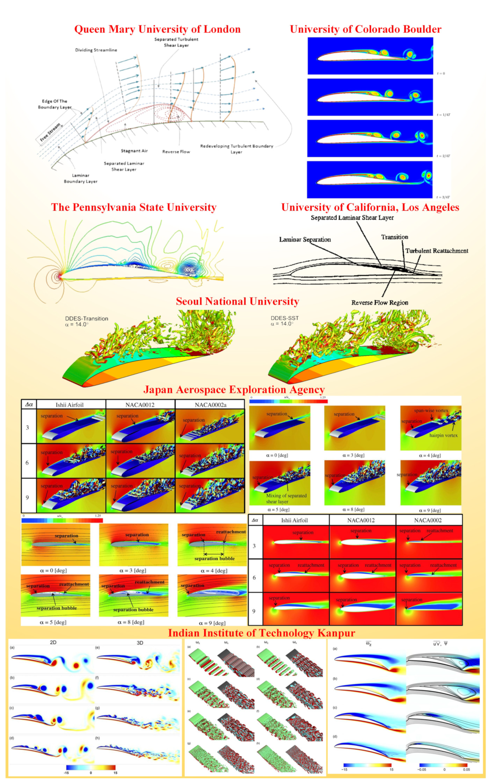
Figure 6.
The control methods of rotary-wing Mars UAVs.

Figure 7.
Mars atmospheric environment simulation setups.

Figure 8.
The experimental setups for hover tests of rotary-wing Mars UAVs.


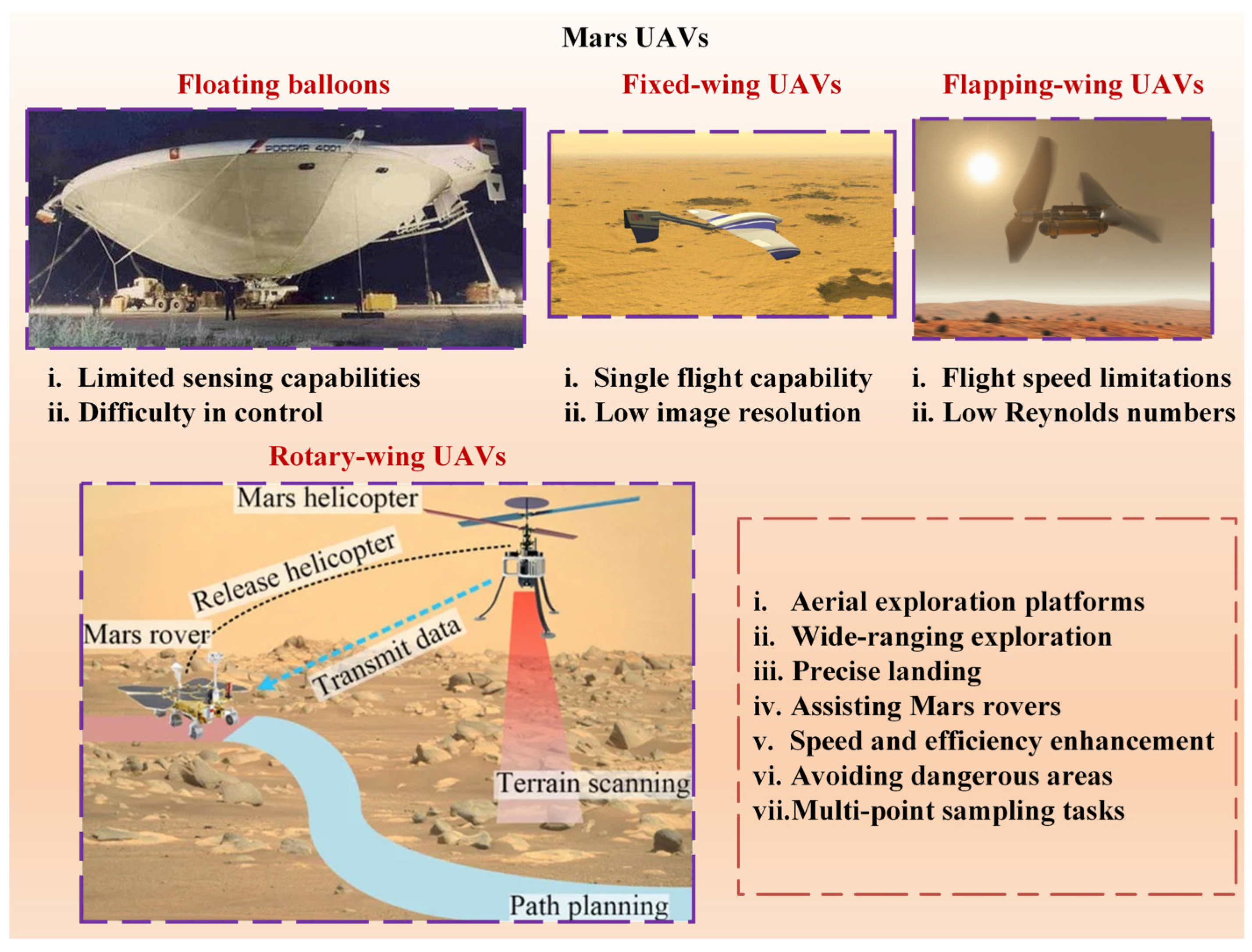
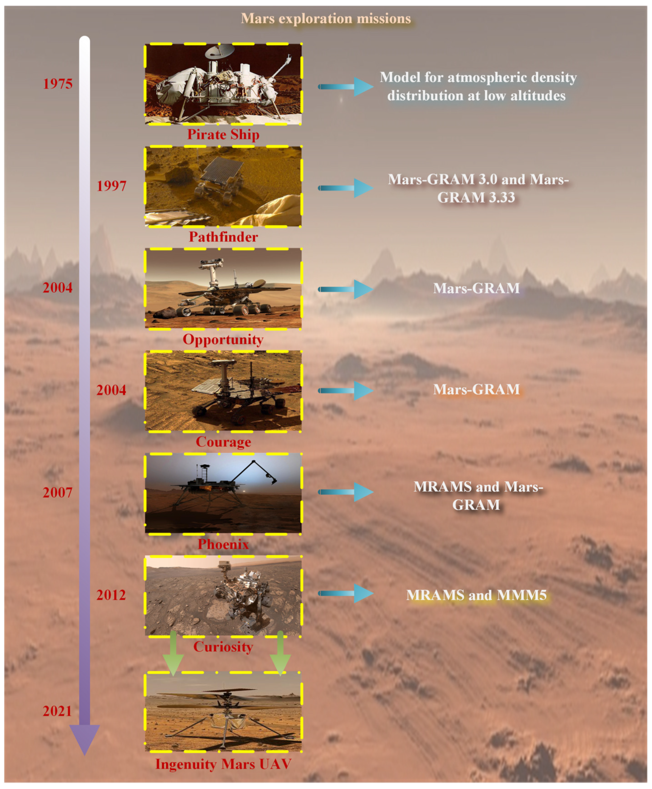
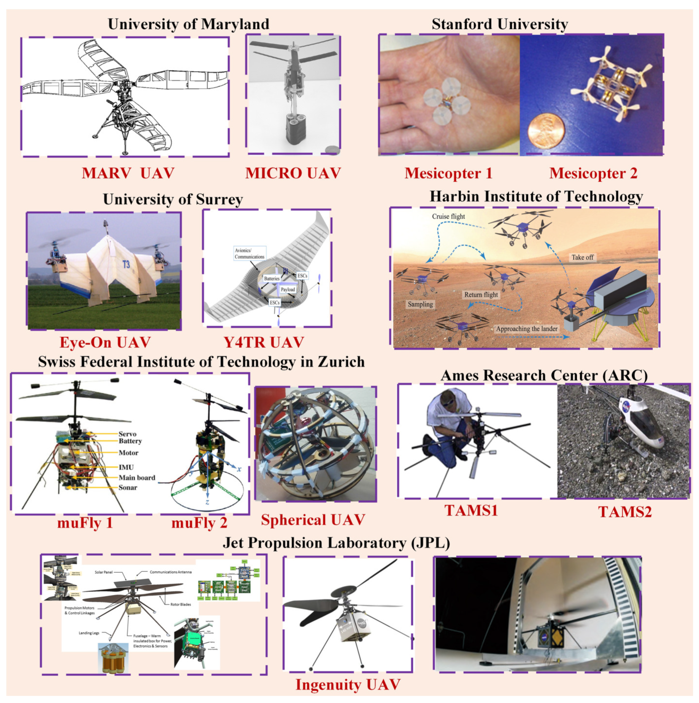
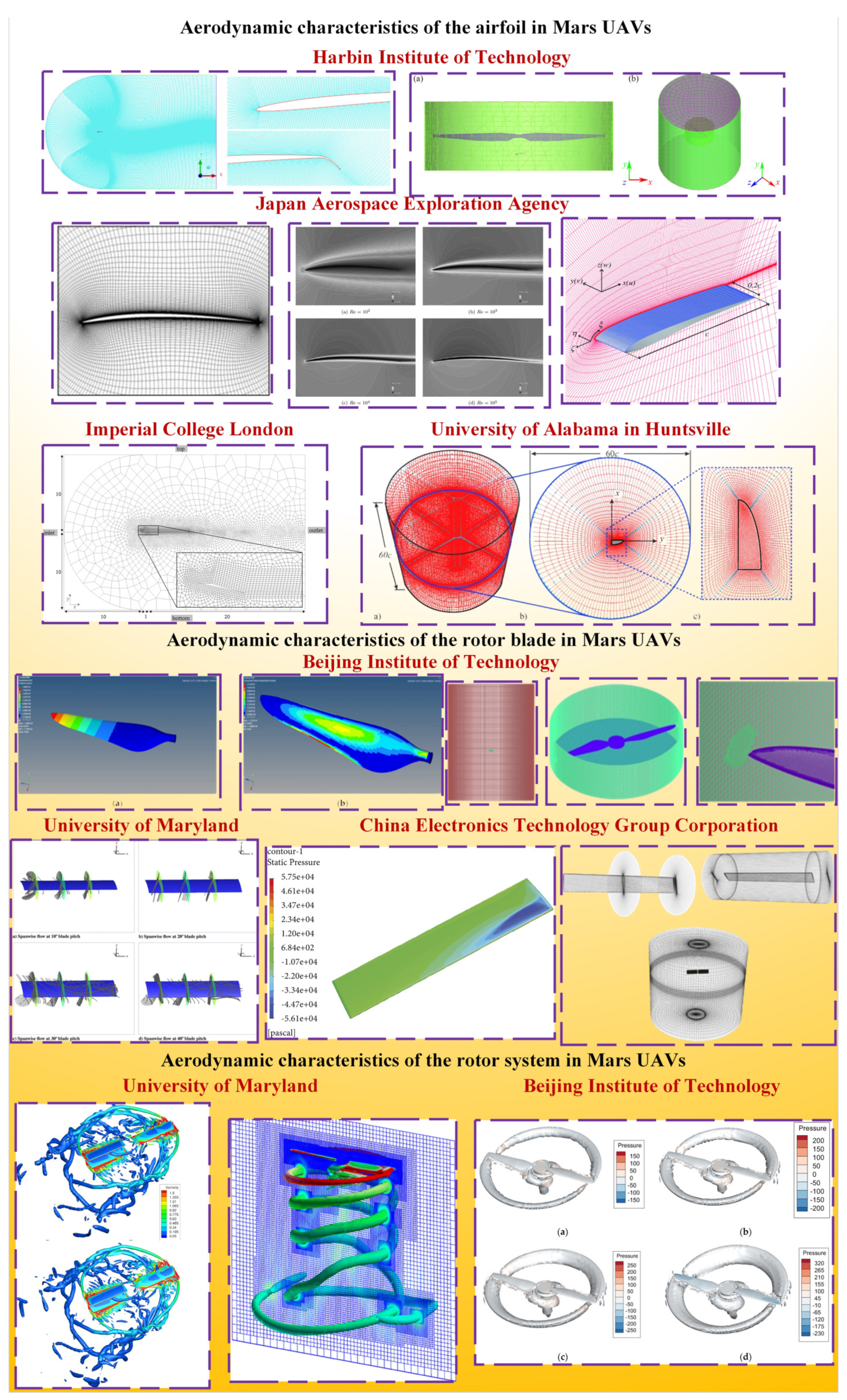
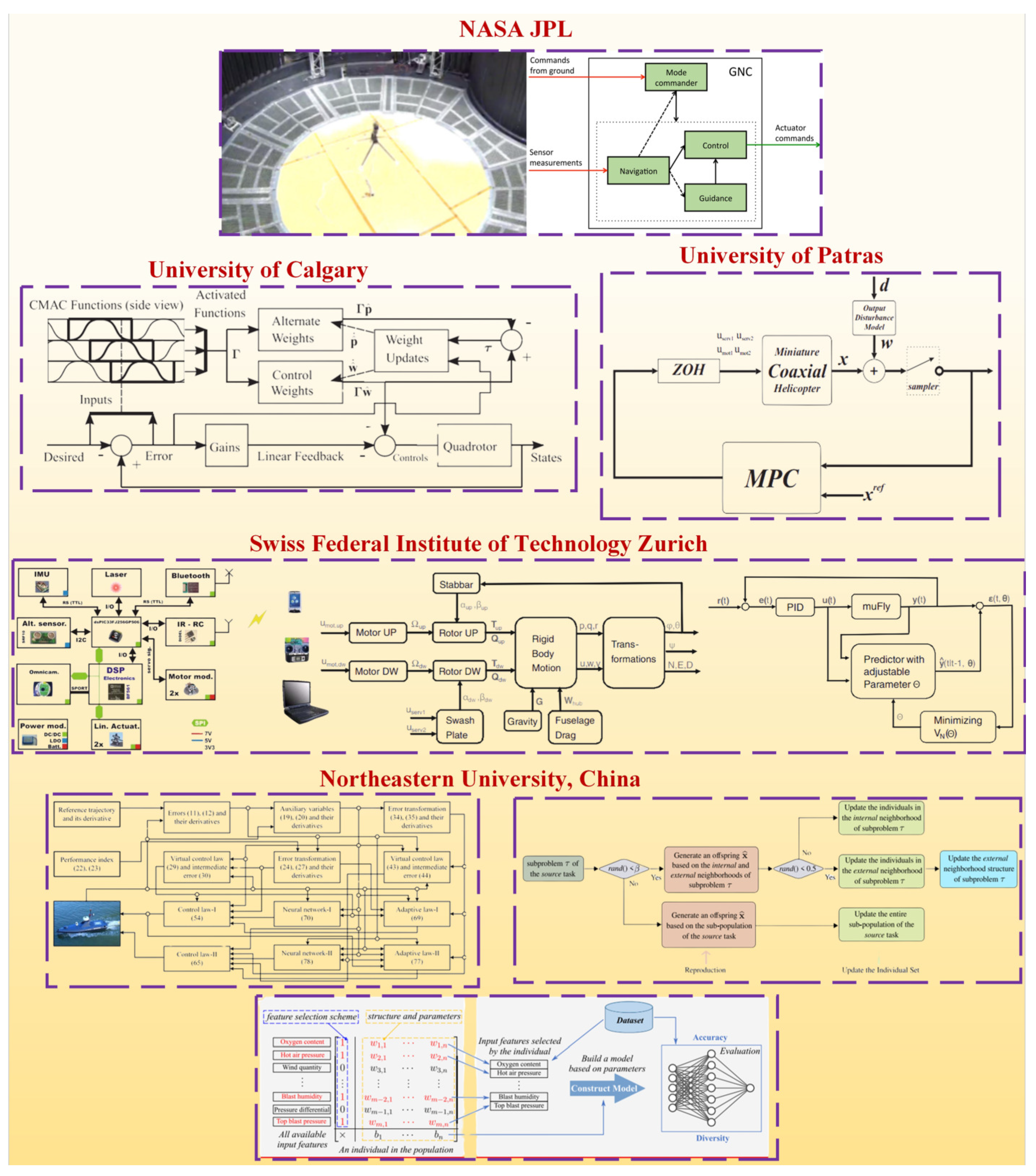
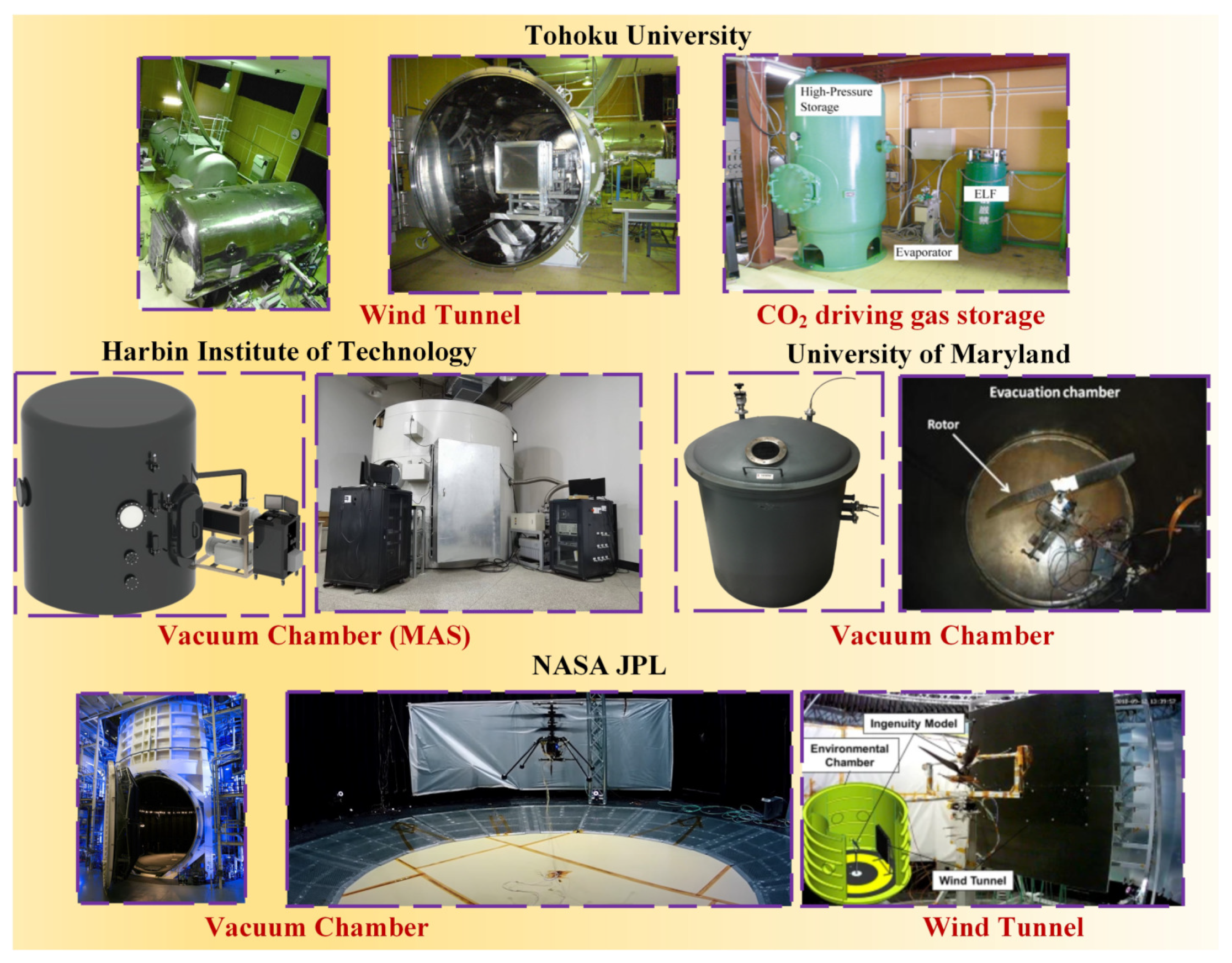
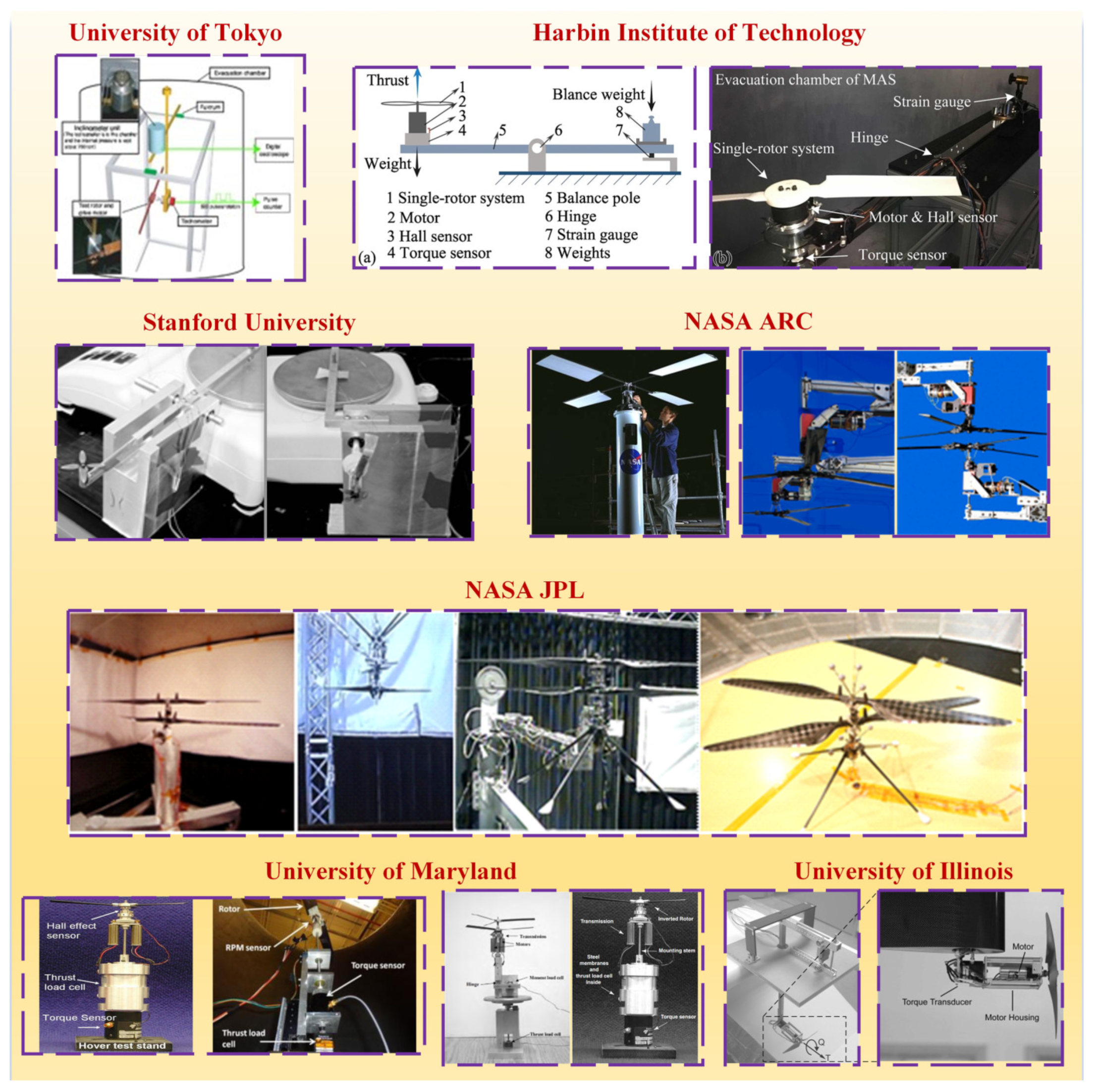
Table 1.
Comparison of flight environments between Mars and Earth.
| Environmental Parameter | Mars | Earth | Proportion |
|---|---|---|---|
| Gravitational acceleration (m/s) | 3.72 | 9.78 | 0.38 |
| Average surface air pressure (Pa) (m/s) | 640 | 101,300 | 0.0075 |
| Surface atmospheric density (kg/m) | 0.0167 | 1.22 | 0.014 |
| Average surface temperature (K) | 210 | 288 | 0.73 |
| Specific gas constant (J/g·K) | 0.189 | 0.287 | 0.67 |
| Sound velocity (m/s) | 227 | 320 | 0.72 |
| Dynamic viscosity (kg/m·s) | 1.289 × 10 | 1.789 × 10 | 0.72 |
| Atmospheric composition | 95% CO, 2.7% N, 1.6% Ar, 0.03% HO | 78% N, 21% O, 1% Ar | – |
Table 2.
Atmospheric models that have been employed in successful Mars missions.
| Detector Name | Atmospheric Model |
|---|---|
| The Pirate Ship | Model for atmospheric density distribution at low altitudes (150 km) |
| Pathfinder | Mars-GRAM 3.0 and Mars-GRAM 3.33 |
| Scott and Amundsen | Mars-GRAM 3.7 |
| Opportunity | Mars-GRAM |
| Courage | Mars-GRAM |
| Phoenix | MRAMS and Mars-GRAM |
| Curiosity | MRAMS and MMM5 |
Table 3.
Mars UAV proposal and parameters.
| UAV Name | Institution | Wingspan | Total Mass | Propulsion System | Power Source | Endurance | Year |
|---|---|---|---|---|---|---|---|
| MICOR | Maryland | 15.24 cm | 103 g | Battery driven | LiMnO cells | 5 min | 2001 |
| MARV | Maryland | 4.266 m | 50 kg | BLDC motor | PEM fuel cells | 39 min | 2003 |
| Mesicopter 1 | Stanford | – | 3 g | – | – | – | 2000 |
| Mesicopter 2 | Stanford | – | 15 g | – | – | – | 2000 |
| Eye-On | Surrey | 1.4 m | 15 kg | Twin rotor | LiPo cells | 38 min | 2012 |
| Y4TR | Surrey | 1.0 m | 25 kg | – | – | 60 min | 2016 |
| muFly 1 | ETH Zurich | 15.0 cm | 95.84 g | BLDC motors | LiPo cells | – | 2010 |
| muFly 2 | ETH Zurich | 15.0 cm | 80.31 g | BLDC motors | LiPo cells | – | 2011 |
| Spherical UAV | ETH Zurich | 22.6 cm | 0.59 kg | Contra-rotating motor | 1300 mAh cell | – | 2016 |
| TAMS 1 | ARC | 0.982 m | 3.5 kg | – | – | 6 min | 2002 |
| TAMS 2 | ARC | 1.250 m | 4.6 kg | – | – | 6 min | 2002 |
| Ingenuity | JPL | 1.2 m | 1.8 kg | BLDC motor | Li-Ion cells | 2 min | 2021 |
Table 4.
The aerodynamic characteristics of rotor systems for rotary-wing Mars UAVs.
| Institution | Dimensionality | Blade Diameter | Aerodynamic Parameters | Year |
|---|---|---|---|---|
| Imperial College London | 2D (triangular airfoils) | – | 2023 | |
| JAXA | 2D (NACA4402) | – | 2006 | |
| Maryland | 3D | 0.4674 m | 2021 | |
| UAH | 3D (rectangular wing shape) | 0.48 m | 2021 | |
| CETC | 3D (NACA0012) | 2.286 m | , | 2022 |
| BIT | 3D (clf5605) | 1.21m | 2023 | |
| HIT | 2D & 3D (NACA airfoils) | 0.90 m | , | 2023 |
Table 5.
The rotor surface boundary layer separation for rotary-wing Mars UAVs.
| Institution | Airfoil | Reynolds Number | Separation Edge | Year |
|---|---|---|---|---|
| Queen Mary College | – | – | Leading | 1969 |
| Penn State University | Eppler 387 | 100,000 | leading & trailing | 1996 |
| University of California | Eppler 387, APEX airfoils | 100,000–200,000 | Leading | 1997 |
| University of Colorado | Eppler 387 | Eppler 387 | Leading | 2008 |
| JAXA | Ishii airfoils, NACA0002, NACA0012 | 24,000 | Leading and trailing | 2014 |
| Seoul National University | Eppler 387 | 100,000 | Leading and trailing | 2015 |
| IIT Kanpur | Eppler 61 | 100–87,000 | Leading and trailing | 2019 |
Table 6.
The control methods for rotary-wing Mars UAVs.
| Institution | Control Method | Year |
|---|---|---|
| ETH Zurich | Attitude and altitude control | 2008 |
| University of Patras | Predictive attitude–altitude control | 2008 |
| University of Calgary | Direct approximate-adaptive control | 2011 |
| China Jiliang University | Robust terminal sliding mode control | 2014 |
| ITMO University | Passification based simple adaptive | 2016 |
| California Institute of Technology | Collective and cyclic control | 2018 |
| European Space Agency | Trajectory control | 2020 |
| Space Science Institute | Telemetry and navigation camera images to control | 2022 |
| Johns Hopkins Applied Physics Laboratory | Collective and cyclic control | 2023 |
| Harbin Institute of Technology | Group injection control | 2023 |
| Tsinghua University | Global prescribed performance control | 2023 |
| Tsinghua University | Neural network control | 2023 |
Table 7.
Experimental setups for Mars UAVs.
| Institution | Vacuum Device | Rotor Structure | Blade Number | Reynolds Number | Mach Number | Year |
|---|---|---|---|---|---|---|
| Tokyo | Large vacuum vessel | Single rotor | 2 | 2000–8000 | <0.13 | 2004 |
| Stanford | – | Single rotor | 4 | 1000–10,000 | <0.30 | 2003 |
| Illinois | – | Single rotor | 2 | – | 0.13–0.26 | 2011 |
| Maryland | Large vacuum vessel | Single rotor | 2 | 15,000–30,000 | 0.10–0.60 | 2007 |
| Maryland | Large vacuum vessel | Coaxial rotor | 3 | <5000 | 0.30–0.42 | 2016 |
| ARC | NASA vacuum chamber | Single rotor | 3, 4 | 37,000–54,000 | 0.50–0.65 | 2002 |
| JPL | NASA vacuum chamber | Coaxial rotor | 2 | <10,000 | <0.60 | 2018 |
Table 8.
The key technologies for rotary-wing Mars UAVs.
| Key Technology | Technical Challenges |
|---|---|
| Mars near-surface atmospheric environment | ✓ Complex Martian atmospheric conditions ✓ Lack of genuine Martian atmospheric data ✓ Accurate atmospheric models ✓ International collaboration |
| Proof-of-concept prototype | ✓ Feasibility validation ✓ Maximum flight thrust ✓ Flight range ✓ Endurance |
| Aerodynamic characteristics of rotor system | ✓ Airfoil lift–drag characteristics analysis ✓ Rotor system thrust and power ✓ Rotor system structure ✓ Boundary layer separation phenomenon |
| Flight control method | ✓ Uncertainty in atmospheric conditions ✓ Communication latency ✓ Autonomy and intelligent control ✓ Navigation and obstacle avoidance |
| Ground simulation experiment | ✓ Mars atmospheric environment simulation ✓ Rotor system testing setup ✓ Experimental plan ✓ Feasibility analysis |
Disclaimer/Publisher’s Note: The statements, opinions and data contained in all publications are solely those of the individual author(s) and contributor(s) and not of MDPI and/or the editor(s). MDPI and/or the editor(s) disclaim responsibility for any injury to people or property resulting from any ideas, methods, instructions or products referred to in the content. |
© 2023 by the authors. Licensee MDPI, Basel, Switzerland. This article is an open access article distributed under the terms and conditions of the Creative Commons Attribution (CC BY) license (https://creativecommons.org/licenses/by/4.0/).
Share and Cite
MDPI and ACS Style
Zhao, P.; Li, R.; Wu, P.; Liu, H.; Gao, X.; Deng, Z. Review of Key Technologies of Rotary-Wing Mars UAVs for Mars Exploration. Inventions 2023, 8, 151. https://doi.org/10.3390/inventions8060151
AMA Style
Zhao P, Li R, Wu P, Liu H, Gao X, Deng Z. Review of Key Technologies of Rotary-Wing Mars UAVs for Mars Exploration. Inventions. 2023; 8(6):151. https://doi.org/10.3390/inventions8060151
Chicago/Turabian StyleZhao, Pengyue, Ruihan Li, Peng Wu, Huan Liu, Xifeng Gao, and Zongquan Deng. 2023. "Review of Key Technologies of Rotary-Wing Mars UAVs for Mars Exploration" Inventions 8, no. 6: 151. https://doi.org/10.3390/inventions8060151