1. Introduction
Hybrid rocket motors, incorporating both solid fuel grains and liquid or gaseous oxidizers, have gained significant attention for their promising applications in the field of propulsion [
1,
2,
3,
4,
5,
6]. The fuel is housed within the combustion chamber in the form of a cylinder, featuring one or more hollowed-out channels, known as ports, along its axis. The oxidizer is introduced into the combustion chamber through a single-fluid feed system. The pioneering development of a hybrid rocket engine is credited to Sergei Korolev, whose rocket, named GRID09, first took flight in 1933 [
5]. Generating 500 N of thrust and reaching an altitude of 1500 m, the rocket utilized liquid oxygen as the oxidizer, a compound still in use today. The solid-state fuel comprised a mixture of crude oil and rosin (colophony). Current space launchers use solid propellant in one or several of their stages and almost all of them use an ammonium perchlorate (AP, NH4Cl4O)-based propellant, often combined with aluminum (Al) powder, leading to the emission of various chlorinated hazardous exhaust products [
7,
8,
9]. Efforts are being made to replace these polluting propellants with alternatives that offer similar properties but are environmentally friendly [
10,
11]. The flagship of the European Space Agency, Ariane-5, and the recently commissioned Vega launcher utilize considerable amounts of composite propellant (476 and 122 tons, respectively), resulting in the release of 270 and 71 tons of concentrated hydrochloric acid per launch. Even the American Space Shuttle’s solid rocket boosters contained 998 tons of ammonium perchlorate-based propellant, leading to the discharge of 580 tons of concentrated hydrochloric acid upon complete combustion [
12]. Several studies have investigated diverse fuels used in hybrid rocket engines, including HTPB. Many studies refer to different fuels used in hybrid racket engines, including HTPB (hydroxyl-terminated polybutadiene)/paraffin [
13], mixtures with varying concentrations of crystalline wax and paraffin wax, PolyEthylene wax, High-Density PolyEthylene, Poly-Methyl MethAcrylate (PMMA) fuel grains, and sorbitol [
14,
15]. To enhance the performance of hybrid rocket engines, various additives are developed, as their performance is generally lower compared to liquid fuel engines. Energetic additives, including aluminum at micro and nano scales, have demonstrated the ability to increase the regression rate of hybrid fuels while serving as a dense energy source [
5,
14]. Additionally, boron is considered for improved regression owing to its higher volumetric heat release in comparison to aluminum, despite its limited usability due to ignition difficulties [
16]. Metal hydrides [
17,
18], such as magnesium hydride (MgH
2) and lithium aluminum hydride (LiAlH
4), are being explored for performance enhancement, resulting in an augmented regression rate of paraffin wax. Moreover, the use of polymers [
19] increases the melt viscosity of the wax, thereby reducing the effect of droplet entrainment, and thus the regression rate. Paraffin stands out as a promising fuel under investigation for use in hybrid propellant rockets owing to its advantageous attributes such as high regression rate, throttling capabilities, non-toxicity, manufacturability, and cost-effectiveness.
A recent study [
20] suggests potential applications of paraffin-based hybrid rocket propulsion across various market segments, including upper stages, sub-orbital launch vehicles, tactical missiles, small satellite injection systems, and boosters, with anticipated cost reductions future shortly. Furthermore, the use of hybrid propulsion for interplanetary missions is currently being evaluated [
14]. Numerous experimental investigations into paraffin-based hybrid rocket motors have been undertaken, including regression-rate measurements, analyses of fuel properties, and an increased focus on visualizing the combustion process [
21,
22,
23,
24]. However, a published review [
15] reported the limited availability of data on the structural performance of hybrid fuel grains, because this has not been a primary concern in the development of hybrid propulsion. In other studies [
25,
26], the need to investigate the structural performance of paraffin-based propellants was justified by the possible fragmentation of the initially cracked grain, which may result in either fuel loss or nozzle blocking, with the subsequent over-pressurization of the combustion chamber. Operating under low temperatures, hybrid propellant rockets launched from high altitudes (balloon launch, air launch) or employed in the upper stages of launch vehicles (space tugs, orbital transfer vehicles) may encounter challenges that compromise the structural integrity of the propellant grain, leading to the formation of cracks which may also originate during the manufacturing process. While certain additives can be utilized to improve the mechanical properties, this improvement may come to the detriment of other important parameters of the propellant, including the regression rate. Furthermore, as highlighted by Andrianov et al. [
27], specific conditions during the manufacturing process can lead to the formation of radial cracks in relatively small solid propellant grains, resulting in local overheating of the structural casing and potentially jeopardizing the structural integrity of the motor. Additionally, the presence of a radial crack in a paraffin grain can induce alterations in the initial shape of the grain’s port due to the combustion within the crack. Therefore, the issue of crack formation in the solid propellant grain of a hybrid propulsion system should not be ignored. However, the utilization of paraffin as a fuel on a large scale is hindered by its high brittleness and low mechanical strength [
28]. To address its suboptimal structural performance, some additives can be used to improve the mechanical properties of the propellant, even if to the detriment of other important parameters of the propellant, such as the regression rate [
29]. Several studies have investigated the development of various paraffin-based fuels. For instance, Y. Pa et al. [
28] studied the thermal, mechanical, and ballistic performance of paraffin–aluminum (P–Al), paraffin–boron (P–B), and paraffin–carbon black (P–CB) fuels. They found that the addition of polymer and metallic additives improved the mechanical strength of the fuels, accelerated oxidation, and enhanced the heat release rate during combustion.
This study aims to assess the mechanical properties and microstructural characteristics of pure paraffin specimens and specimens comprising a mixture of pure paraffin, stearic acid, and coal, both before and after exposure to negative temperature treatment. Additionally, a lab-scale hybrid rocket motor using gas oxygen as an oxidizer has been used to conduct firing tests with paraffin-based fuels containing stearic acid and coal components. The new propellant is designed to be one that does not produce pollutants such as chlorine, hydrochloric acid, ammonia, aluminum, etc., as byproducts of the combustion reaction.
2. Materials and Methods
2.1. Fuel Preparation
For the development of a new propellant, an examination of pure paraffin as a reference and a combination of pure paraffin, stearic acid, and coal was conducted, focusing on mechanical properties, microstructural characteristics, and ignition performance. The addition of stearic acid and coal powder to the mixture, as detailed in
Table 1, was intended to improve the structural and thermal stability of the paraffin-based fuels, and the specific properties of these compounds are shown in
Table 2.
The mixture was prepared through heating in an electric furnace at 350 K and continuously stirring for 15–20 min to achieve homogeneity. Subsequently, it was poured slowly and continuously into a casting mold. To prevent adhesion between the paraffin and the mold, a thin layer of diesel was applied to the inner edges of the casting mold, simplifying the removal of the fuel grain after the paraffin solidified. A previous study [
32] reported that paraffin wax exhibits volumetric shrinkage (15–25%) during the transition from a liquid to a solid phase, which varies based on the wax grade. Therefore, to avoid the formation of air bubbles and other discontinuities in the fuel grain during casting, the molten paraffin mixture was poured slowly and continuously into the casting mold in a single pour. Examination of the fractured surface of the fuel grain revealed no significant cracks or bubbles along the grain length.
2.2. Mechanical Performance Tests
Both the pure paraffin specimens and the paraffin specimens containing stearic acid and coal were subjected to tests for tensile, compressive, and flexural strength under two distinct conditions: storage at room temperature and exposure to sub-zero temperatures (−21 °C) for 24 h. For each type of material, test, and condition, three specimens, whose codifications are presented in
Table 3, were evaluated.
To assess the mechanical properties of the new propellant, three types of specimens were designed for tensile, compression, and bending tests. The dimensions and geometry of these specimens are detailed in
Figure 1.
The specimens were produced using the additively manufactured ABS (acrylonitrile butadiene styrene) molds presented in
Figure 2.
After preparing the molds, both paraffin and the new propellant were introduced into the molds and heated to 350 K using an electric kettle. Continuous mixing was maintained throughout the melting process until both the paraffin and the new propellant reached a liquid state. The crucial step in this process was to ensure continuous mixing, particularly for the new propellant, to achieve a more homogeneous mixture. Subsequently, the molten material was poured into the molds, stirred thoroughly, and allowed to slowly cool to room temperature.
Figure 3 illustrates the raw paraffin wax used and shows images capturing various stages in the preparation of the paraffin and new propellant.
Before casting, the molds were coated with diesel to prevent the propellant from adhering. For each testing type, eight specimens of both pure paraffin and the new propellant were prepared. Half of these samples were tested at room temperature, while the others were subjected to testing at −21 degrees Celsius.
Figure 4 illustrates the specimens obtained for testing.
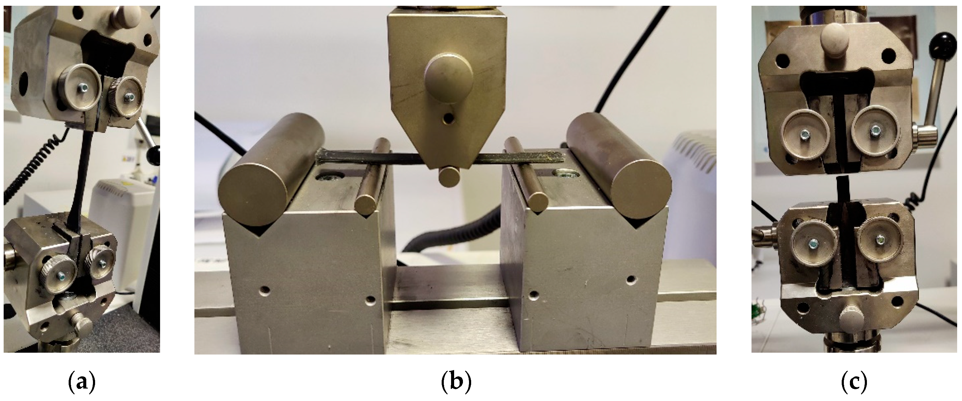
All mechanical tests were performed using an Instron 3369 mechanical testing system (Instron, Norwood, MA, USA), which was equipped with dedicated devices for tensile, bending, and compression testing, as depicted in
Figure 5.
2.3. Mechanical Performance Tests
The pure paraffin specimens and the paraffin mixture were investigated in an as-prepared state and after testing using scanning electron microscopy (SEM) with an FEI Inspect F50 scanning electron microscope—SEM (FEI Company, Brno, Czech Republic), and optical microscopy using a Motic SMZ-171 7.5X-50X Zoom Stereo Microscope (Motic Asia Kowloon, Hong Kong, China). Due to the nature of the fracture of tensile specimens, particular attention was focused on the analysis of the fracture surfaces. Therefore, sections from the damaged specimens were cut and affixed onto a double-sided conductive carbon tape to hold the sample on the stub and were scanned using an acceleration voltage of 20 kV. Because paraffin wax is a nonconductive material, the surface morphology of the specimens was analyzed via SEM after the samples were sputter-coated with gold using the SC7620 Mini Sputter Coater/Glow Discharge System (Quorum Technologies, Laughton, East Sussex, UK).
2.4. Numerical Simulation Performance
To study the performance of a rocket engine, a set of numerical simulations was conducted in the initial phase. The simulations were performed using the ProPEP software, aiming to comparatively observe, both for pure paraffin and for the new recipe, the maximum specific impulse (Isp), the maximum combustion temperature in the combustion chamber, and the concentration of CO and CO2 in the combustion products from the combustion chamber as a function of the variation of the oxidizer/fuel (O/F) ratio from 0 to 8. This was conducted for a rocket engine with a combustion chamber pressure of 10 bar and an exhaust pressure of 1 bar.
2.5. Engine Test
For the new mixture, sticks of the new propellant were created and assessed using a lab-scale ballistic test motor to verify the stability and functionality of the new propellant during operation on the test bench.
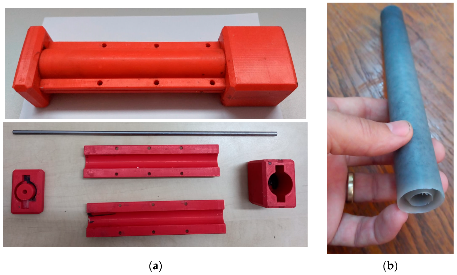
In this regard, a stick of the new propellant was cast, as shown in the figure below. A mold obtained from a 3D printer was used for casting. To obtain the central hole of the stick, a metal rod was used, as illustrated in
Figure 6a. The dimensions of the stick were 2.54 cm for the outer diameter and 1 cm for the inner diameter. In addition, a cylindrical shape with a coaxial central port was additively manufactured for casting the new propellant.
Figure 6 presents the mold obtained from 3D printing and the stick of the new propellant.
In
Figure 7, the testing stand for the rocket engine is depicted. More details about the testing stand can be found in the sources [
33,
34].
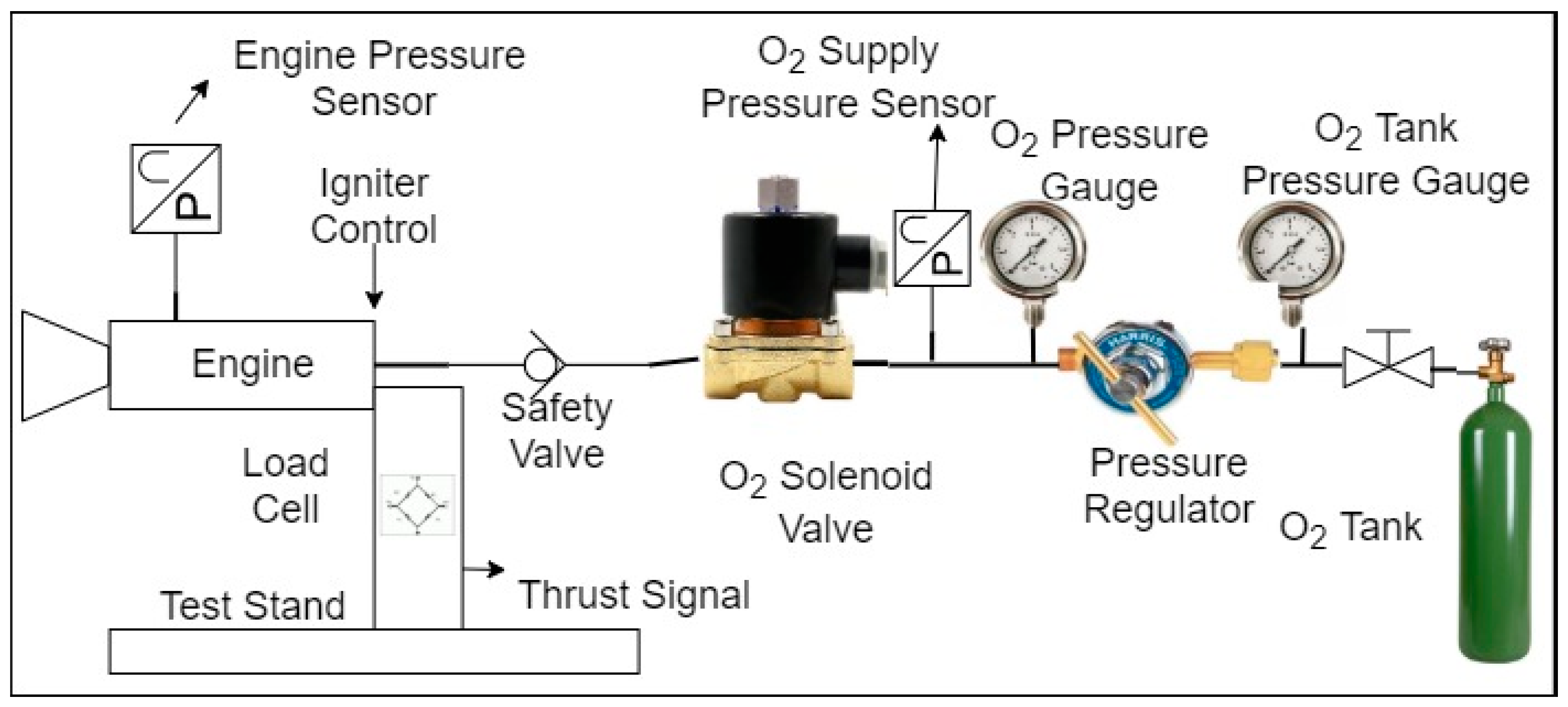
Gaseous oxygen was utilized as the oxidizer. The experimental hybrid motor arrangement at the laboratory scale consisted of an oxidizer supply system, a stainless steel combustion chamber, a convergent–divergent nozzle, and an ignition system, as illustrated in
Figure 8.
The oxidizer mass flow rate entering the combustion chamber was systematically regulated through the utilization of a pressure regulator. Gaseous oxygen was introduced into an oxidizer-settling chamber with a diameter of 55 mm and a length of 33 mm. Injection into the combustion chamber was facilitated with an axial-flow injector plate. The cylindrical combustion chamber, with an inner diameter of 42 mm and a length of 150 mm, housed the solid fuel. To maintain an 8 mm gap between the fuel port and the nozzle entry, the fuel grain length was consistently upheld at 142 mm within the combustion chamber. This post-combustion chamber facilitated the interaction of unburnt paraffin with liquid oxygen before exiting the nozzle.
A meticulous firing test procedure was adhered to, to ensure the accuracy of the test. The firing device employed a mixture of potassium nitrate and sugar, a standard formulation widely used in igniting solid rocket engines for rocketry challenges. The selected proportions for the mixture were 60% potassium nitrate and 40% sugar to enhance safety, as the igniter’s performance was not a focal point of this study. While various additives like corn syrup, aluminum powder, and nitrocellulose could augment the igniting mixture to influence burning time or heat generation, the decision was made to adhere to the proportions recommended by Richard Nakka to streamline the process.
The ignition process involved nickeline wires powered by a 12 V source, as illustrated in
Figure 9. The application of current through the nickeline wire rendered it incandescent, initiating the ignition of the mixture. It is imperative to maintain a constant heating source temperature during the preparation of an ignition mixture from potassium nitrate and sugar, following established manufacturing guidelines. Deviations from these temperature indications or the use of an open flame instead of an electric stove are potential causes of accidents associated with this process.
The test bench features a horizontal metallic frame equipped with a vertical load cell. The motor is positioned horizontally, exerting force perpendicular to the load cell. This design minimizes the test bench’s footprint and allows for the jet plume to be directed away from the pressurized oxygen tank. The load cell has a maximum measuring force of 250 kgf, chosen to accommodate various sizes of rocket engines without compromising accuracy. With a sensitivity of 2 m V/V, the load cell produces a maximum signal of 10 mV at 250 kg for a 5 V excitation voltage. Assuming a 6-sigma accuracy of the data acquisition system at 0.4 μV, the measurement accuracy is estimated at 10 g with a resolution of approximately 1 g, employing a sampling period of 9.227 ms. While faster sampling speeds are attainable, they come at the expense of reduced accuracy.
3. Results
3.1. Mechanical Performance
3.1.1. Tensile Testing
Histograms depicting average tensile test results for both the pure paraffin and paraffin mixture specimens in their as-prepared and cold-treated states are presented in
Figure 10a–d. The examination of load and ultimate tensile strength (UTS) revealed significant variations dependent on the chemical composition and testing temperature. Specifically, the M_c specimens, tested at negative temperature, exhibited the highest load (45.6 N) and UTS (2.1 MPa). In line with this trend, the P_c samples displayed substantial strength, but 50% lower than M_c. Conversely, the as-prepared specimens, both of pure paraffin (P_a) and the paraffin mixture (M_a), exhibited significantly lower values. Young Modulus analysis revealed a distinct hierarchy among the specimens, with M_c samples showing the highest modulus (165.9 MPa), reflecting greater stiffness, followed closely by P_c (147.7 MPa), M_a (63.1 MPa), and P_a (26.78 MPa).
The samples with the highest strength also exhibited the smallest elongations. The assessment of elongation at the point of tensile strength showcased a pattern evidenced by stress–elongation curves (
Figure 11). The observed variations in elongation provide insights into the materials’ deformation characteristics and may be crucial for understanding their mechanical behavior. Sample P_a exhibited the highest elongation, indicating greater ductility, followed by P_c, M_a, and M_c. These findings suggest that P_a exhibits a more pliable behavior under tensile stress, while M_c displays a more rigid response at the cost of less resistance.
The observed differences in mechanical behavior based on testing temperature necessitate further investigation into this influential parameter concerning other mechanical properties and microscopic characteristics.
3.1.2. Compression Testing
Figure 12 presents average compression test results for pure paraffin and paraffin mixture specimens in their as-prepared and cold-treated states, focusing on compression behavior and the influence of testing temperature. Similar to the trend observed in the tensile tests, M_c specimens exhibited the highest compression load at 246.7 N, indicating superior strength. P_c specimens followed closely with a load of 157.0 MPa, demonstrating notable strength compared to the specimens tested at room temperature, but with considerably higher strength compared to M_a and P_a. Examining compression elongation, M_a demonstrated the highest value at 1.025 mm, reflecting greater deformation under compression. P_c, M_c, and P_a followed with values of 0.9 mm, 0.7 mm, and 0.5 mm, respectively. This suggests that M_c exhibits a more ductile response under compression, while P_a shows a more rigid behavior with less deformation. Intriguingly, the results related to the compressive elongations present an opposing trend to the findings obtained for tensile elongations.
During the compression test, the cold-treated specimens exhibiting the highest compressive strength values also demonstrated the highest compressive elongations, indicating the complex interplay between material composition, testing temperature, and mechanical properties during different modes of deformation.
3.1.3. Three-Point Bend Testing
The three-point bending results of pure paraffin and the new propellant specimens highlight variations in elongationelongationen, respectively, suggesting a strong tendency to decrease ductility (
Figure 13).
The mechanical tests, encompassing tensile, compression, and bending properties, revealed that the specimens of the new propellant developed in these experiments exhibited the highest strength when tested at a negative temperature. This consistent trend across the three mechanical testing types emphasizes the superior mechanical performance of the paraffin mixture in comparison to pure paraffin, both under ambient and cold-temperature conditions. These findings suggest that the developed propellant, specifically designed for low-temperature applications, exhibits superior strength characteristics across various modes of mechanical loading, thereby substantiating its promising potential for practical use in hybrid rocket engines.
3.2. Macrostructural Investigation
The macrostructural investigation involved an examination and fractographical evaluation of both pure paraffin and the new propellant specimens in their as-prepared state and after undergoing cold testing. Optical images at ×10 magnifications were captured to inspect the surface of the tensile specimens and the cross-sectional surface rupture after tensile testing at both room temperature and negative temperatures.
Figure 14 and
Figure 15 showcase these images, revealing a predominantly homogeneous structure along the edges and a central region devoid of visible pellets or micro-cracks. Certain regions of the specimens, especially within the paraffin mixture, exhibited impurities and internal micro-voids, as can be seen in both surface (
Figure 14a–d) and tensile fracture surfaces (
Figure 15a–d) of the test specimens. However, as shown by the mechanical tests, these features did not significantly influence the mechanical strength of the paraffin mixture, which was superior in both ambient and negative temperatures.
The observed impurities and micro-voids could be attributed to factors such as the raw material variations, the manufacturing process, or the specific composition of the paraffin mixture. Interestingly, despite their presence, the mechanical tests demonstrated that these imperfections did not compromise the material’s strength, highlighting its resilience and potential for application in hybrid rocket systems, where structural integrity is crucial for reliable performance. Further investigation into the origin and distribution of these features using scanning electron microscopy could provide valuable insights into the material’s structural characteristics.
Microstructural Investigation
Scanning electron microscopy (SEM) analysis was used to investigate the microstructure of fracture surfaces in both pure paraffin and the new propellant tensile specimens. The microstructural features are depicted in
Figure 16 for pure paraffin specimens in both the as-prepared and cold-treated states, while
Figure 17 displays SEM images of fracture surfaces for new propellant specimens in both conditions. The SEM images in
Figure 16 and
Figure 17 reveal a similar microstructure and morphology between pure paraffin and the new propellant. However, a noticeable increase in densification and a reduction in voids were observed in the fracture surfaces of both pure paraffin and the new propellant after cold treatment. Interestingly, specimens tested at room temperature exhibited a more fragile appearance compared to those tested at negative temperatures.
Despite the superior mechanical properties of pure paraffin specimens over paraffin mixture specimens, the microstructural investigation did not unveil any characteristics that could justify this behavior. Most probably, the mixture of pure paraffin with stearic acid and coal improved strong interfacial interaction between structural elements that increased the mechanical strength of the new fuel.
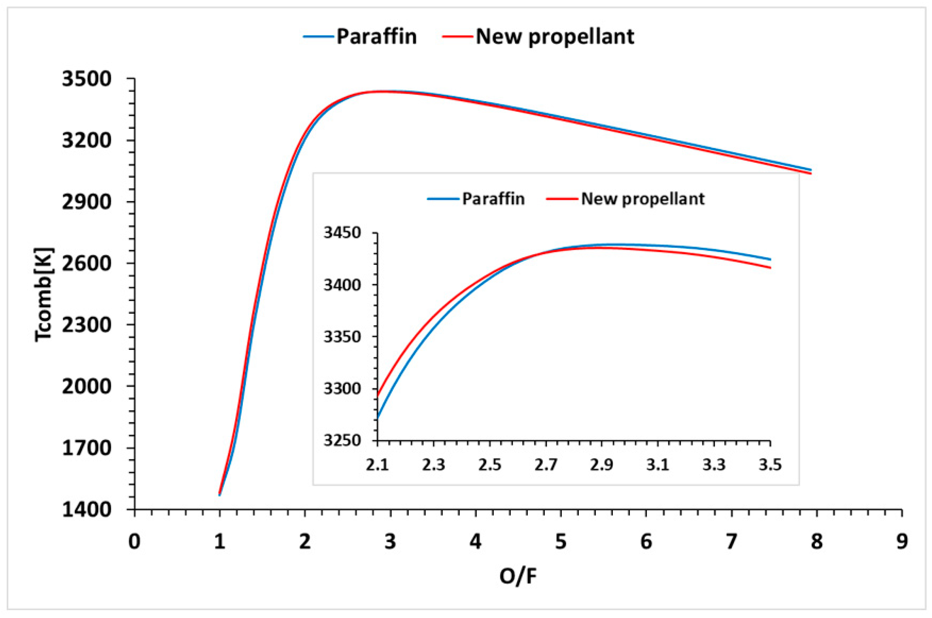
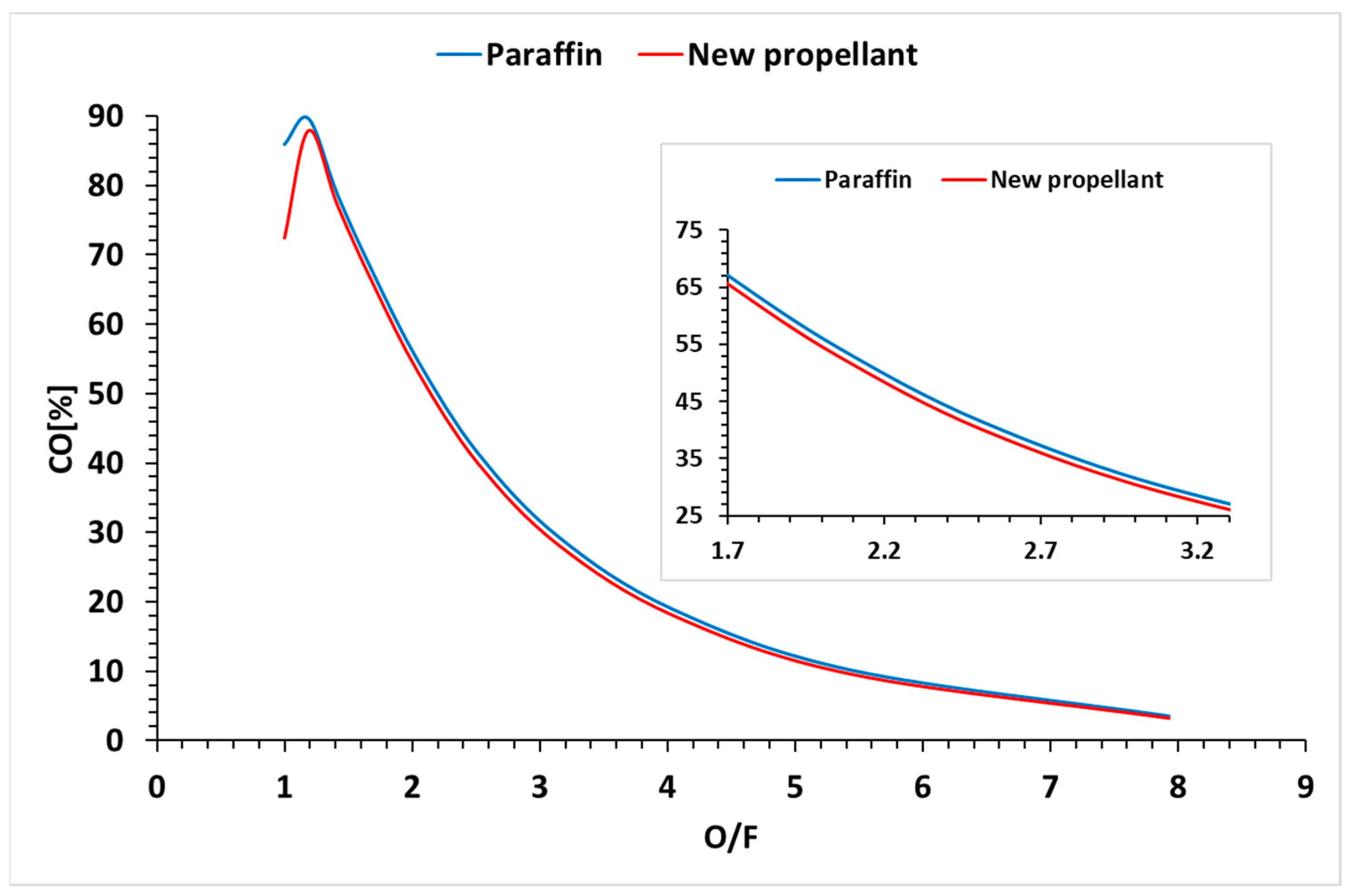
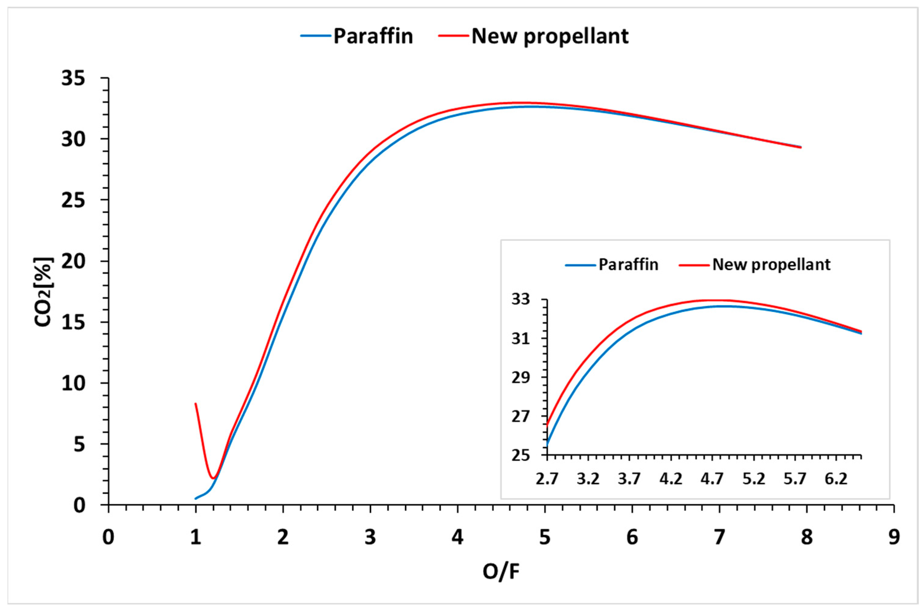
3.3. Numerical Simulation Engine Performance
Following the numerical simulations in the ProPEP software, the obtained results are depicted in the following figures.
Figure 18,
Figure 19,
Figure 20 and
Figure 21 illustrate the variation of specific impulse, combustion temperature, and the concentration of CO and CO
2 as a function of the O/F ratio.
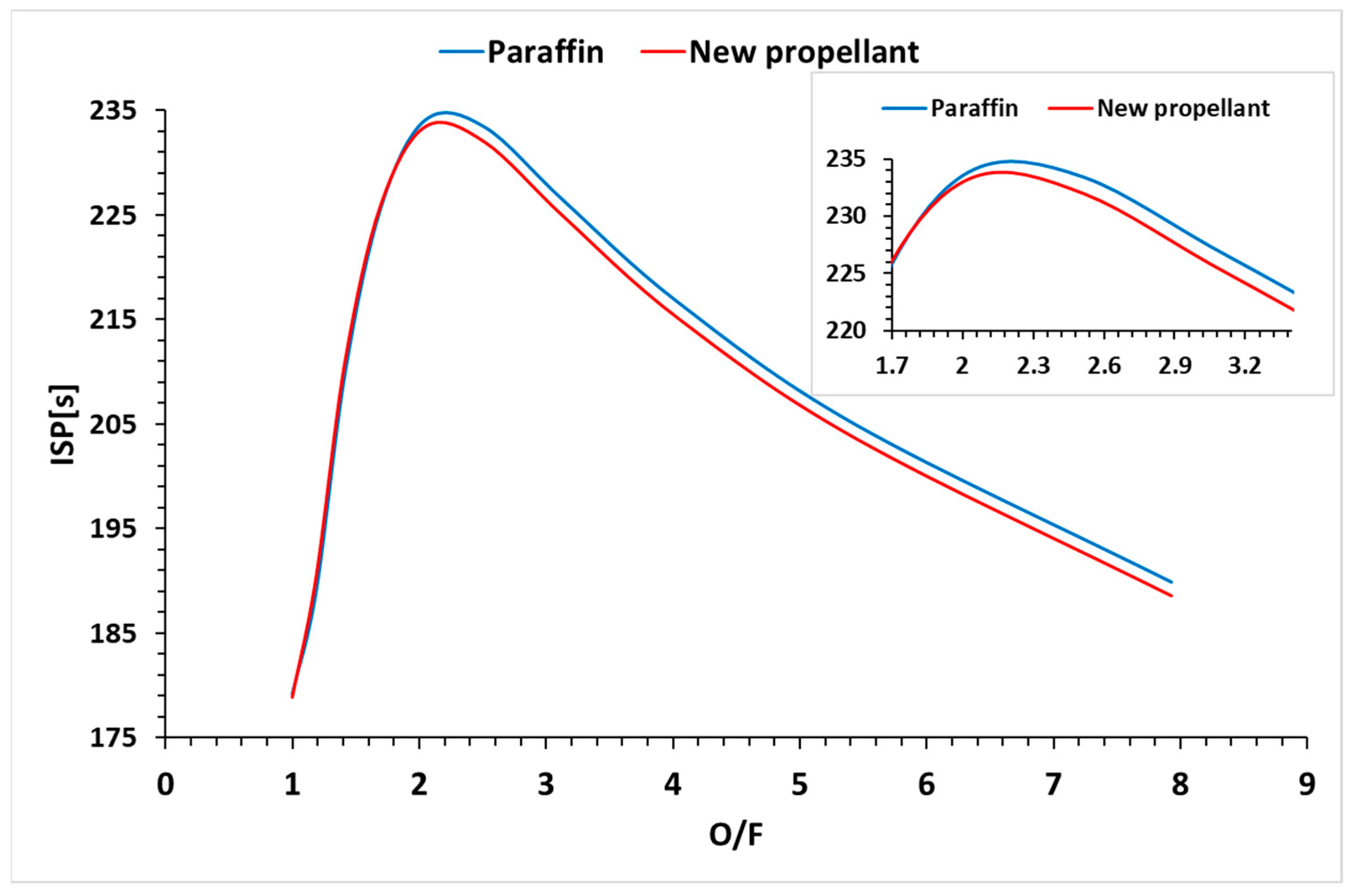
It can be observed from the above figure that the specific impulse for the two propellants differs very little at each O/F ratio. It is noticeable that the maximum specific impulse is achieved for both propellants around the O/F value of 2.2. This ratio was considered for the experimental part as well.
It can be observed from the
Figure 19 that the combustion temperatures between the two propellants do not differ significantly based on O/F. The maximum combustion temperature, T_comb, is around the O/F value of 2.8. Although the combustion temperature significantly contributes to the specific impulse value, the experimental O/F ratio chosen is not 2.8 but the previously mentioned value for ISP, namely, O/F = 2.2.
Following the simulations of the combustion of paraffin and the new propellant, it was observed that there were no hazardous substances, as would be the case for traditional solid propellants based on ammonium perchlorate or aluminum. Thus, no chlorine, ammonia, or aluminum-based compounds appear after combustion. Consequently, for the simulated motor, the resulting components include H2, H2O, O2, CO2, CO, and other combinations in insignificant percentages.
It can be noted that the CO concentration decreases with the increase in the O/F ratio for both propellants, and the differences between concentrations are not significant.
Table 4 presents the percentage difference of paraffin compared to the new propellant for ISP, Tcomb, and for the mass concentration of CO and CO
2.
As can be observed for ISP, which is the most important variable, the errors are very small, below 1%.
As for the CO2 concentration, it reaches a maximum for an O/F ratio around 4.7. For experimentation, as mentioned above, the O/F ratio of 2.2 was chosen, indicating a mass concentration value of around 15% of the total combustion gas mass.
3.4. Engine Test Performance
Due to the difficulty in precisely calculating the performance of the hybrid rocket engine, mainly because the burn rate of the new propellant needs to be known, conducting a ballistic test, which falls outside the scope of this study, is necessary. Consequently, the motor with the new propellant was tested to assess its stability during operation, to observe if the combustion was stable, and to identify any potential serious issues that could jeopardize the integrity of the motor.
Figure 22 depicts an image captured during the ignition of the rocket motor with the new propellant.
Following the test, it was observed that the entire grain burned completely, with no remaining unburned pieces or areas where the combustion was more intense or less intense. The variation in thrust was extracted from the data acquisition system, and it is displayed in the figure below.
Following the tests performed, the plot from
Figure 23 presents the variation of the thrust and the pressure inside the rocket engine.
The results obtained following the tests show that the rocket engine worked without destroying itself, and the parameters obtained correspond to those resulting from the theoretical models from the literature.
From
Figure 23, there are six visible time periods with different pressure thrust levels:
1: Oxygen flow is off, and igniter is off;
2: Oxygen flow is on, the igniter is off, and the motor acts as a cold jet thruster with low pressure and low thrust;
3: The igniter is fired and combustion starts. The pressure and thrust increase significantly. Thrust is almost constant. The burn is very clean, and the flame is invisible in the video, probably because of the high O/F ratio;
4: Thrusts decrease gradually. Some spikes are identified in the recording, probably indicating that some fuel may have detached from the internal surface of the combustion chamber;
5: The fuel is fully consumed. Thrust and pressure are caused only by oxygen flow. Levels are significantly higher than in the “2” interval because the hot combustion chamber is increasing the temperature of the oxygen;
6: The Solenoid valve cuts the oxygen flow. The test is complete.
4. Discussion
One of the main concerns with paraffin-based fuels is their poor mechanical characteristics. Thus, the addition of additives to enhance the mechanical performance of paraffin for use in hybrid rocket engines represents an open field [
3,
35]. The limitations of paraffin-based fuel for hybrid rockets necessitate an exploration of additives to improve regression rates without compromising mechanical properties [
30,
35]. This study investigates the mechanical and microstructural aspects of the novel paraffin-based propellant in comparison with pure paraffin, both before and after exposure to negative temperatures. Understanding these characteristics is essential for optimizing the material’s performance and ensuring its reliability in the demanding conditions of hybrid rocket propulsion systems.
Tensile testing results revealed significant variations in load, ultimate tensile strength, tensile elongation, and Young Modulus among different specimens. Samples M_c exhibited the highest load and UTS, indicating superior strength compared to the pure paraffin specimens. This heightened strength can be attributed to a combination of factors such as material composition, reinforcing agents, and specific processing conditions during fabrication. Therefore, adding additives is not always beneficial in all respects; Y. Pal et al. [
35] found that adding Al and B did not significantly improve the regression rate of the propellant. In contrast, in another study [
28], they demonstrated that these additives could enhance the compressive modulus and strength of the paraffin-based fuel formulations. Several studies have explored different additives to enhance the mechanical performance of paraffin-based fuels, but the influence varied as a function of material and concentration. One additive that has shown promising results is ethylene vinyl acetate (EVA). Kumar and Ramakrishna [
36] achieved a 50% increase in tensile strength by adding 20% EVA to pure wax, while Maruyama et al. [
37] reported a 1.6-times increase. Tang et al. [
30] investigated the influence of adding six different types of additives, including stearic acid, polyethylene wax (A-C6A), ethylene vinyl acetate copolymer (EVA), low-density polyethylene (LDPE), polypropylene (PP), and high-density polyethylene (HDPE) to paraffin fuel. They observed that the mechanical properties were enhanced based on the type of additive and increasing additive mass percentage. The optimal choice for improving compressive strength by 64% relative to pure paraffin was found to be adding a 5% mass of A-C6A to the paraffin matrix, while LDPE proved to be the most effective in enhancing tensile strength, showing an increase of 105.7% with the same mass addition. In other studies, it has been observed that the use of additives (e.g., carbon) contributed to a decrease in mechanical properties [
35] due to the weak interfacial adhesion between the CB filler and paraffin matrix.
However, in this study, the addition of 10% stearic acid and 2% coal powder to the paraffin matrix resulted in increased tensile, compression, and flexural strength at both room and sub-zero temperatures. Tensile strength increased by 28% at room temperature and an impressive 102% at sub-zero temperature compared to pure paraffin. Similarly, the compression strength at room temperature and sub-zero temperature of the new propellant increased by 119% and 55%, respectively, compared to pure paraffin. Additionally, the flexural strength at room temperature and sub-zero temperature of the new propellant increased by 42% and 24%, respectively. These findings highlight the robust performance of the new propellant under both ambient and negative temperatures. The higher UTS of M_c suggests enhanced molecular cohesion and resistance to deformation, making it capable of withstanding higher tensile loads before failure. The influence of temperature on mechanical behavior aligns with findings in other studies [
25,
35], prompting further exploration of temperature effects on various properties and microscopic characteristics. Compression and three-point bend testing also showed variations in strength and elongation among specimens. The notably higher strength of the new propellant (M_c specimens), especially in cold conditions, aligns with expectations and underscores the potential advantages of the new propellant. Macrostructural examination showed a predominantly homogeneous structure with localized impurities and micro-voids. In other cases where additives were used in paraffin mixtures, it was observed that paraffin lumps can form, and the connections between these lumps are not dense, acting as mechanical failure concentrators [
35]. However, the increased mechanical properties are caused by the strong interfacial interaction between the stearic acid, the coal, and the paraffin matrix.
Despite these features, their negligible impact on mechanical strength underscores the material’s resilience. In contrast, Piscitelli et al. [
26] developed four different paraffin waxes in a separate study and reported that the central region of their paraffin samples exhibited traces of pellets, partial liquefaction, and large and numerous internal micro-voids and micro-cracks. They suggested the necessity for both external mechanical pressure and thermal loads, reaching a bulk temperature of at least 110 °C, to address manufacturing challenges. Although the investigations in this study did not identify a significant issue with micro-voids, these measures could be considered in future studies to improve the quality of the newly developed propellant. Also, the data on the structural performance of the new propellant are insufficient to accurately predict the loads experienced during flight. Considering the varying stress strains, axial thrust loads, and radial combustion pressures that will be encountered during full-scale engine operation [
35], a comprehensive examination of mechanical performance under these conditions, as well as a thermal characterization, is needed in the near future.
Scanning electron microscopy (SEM) analysis highlights the microstructural features, showcasing similarities between pure paraffin and the new propellant. The increased densification and reduced voids after cold treatment aligns with expectations, reinforcing the material’s adaptability to varying mechanical loads. However, the addition of the stearic acid and coal to the paraffin matrix improves the mechanical interfacial resistance. This observation resonates with findings in [
3,
35,
38] suggesting a common trend in propellant materials with added additives.
The investigation of fracture surfaces on specimens tested at room temperature revealed a generally more brittle appearance compared to those tested at sub-zero temperatures. The variation of ductility as a function of exposure and test temperature is also supported by the results of the tensile and compression mechanical testing, in which specimens tested at cold temperatures had significantly higher deformation than those tested at room temperature.
These results open new future research directions, including exploring manufacturing conditions, incorporating additional additives, and examining the effects of nozzle temperatures on mechanical properties. Additional microscopy investigations can evaluate impurity origins and distributions, advancing the understanding of the material’s structural characteristics.
Regarding the performance of the new propellant, as observed from the numerical simulations, there is very little difference compared to the performance of pure paraffin. Similar to the approach in [
35], where the enhancement of properties was achieved by adding coal and MgB2 to paraffin, in this study, the improvement of mechanical performance was realized through an innovative new formula by adding stearic acid and coal without compromising the rocket engine’s performance. This type of propellant is considered environmentally friendly, aligning with the pursuit of obtaining solid or hybrid propellants with high specific impulse that are non-polluting [
11].
Regarding the combustion products of the new propellant, it was observed through simulations that there were no traces of ammonia, hydrochloric acid, or aluminum, making it an environmentally friendly propellant, unlike other solid propellants presented in [
12]. For the simulated engine varying the O/F ratio, the resulting components included H
2, H
2O, O
2, CO
2, CO, and other combinations in insignificant proportions, unlike other propellants presented in [
7,
8,
9,
10].
Regarding the testing of the new propellant in the rocket engine on the test bench, this test proceeded under normal conditions, presenting a thrust-versus-time graph similar to other experienced propellants.
Future testing will be attempted with liquid oxygen to achieve comparable or enhanced performance of the engine.
5. Conclusions
Following the analysis of the new propellant through numerical simulations, it was observed that the addition of stearic acid and coal powder does not significantly degrade the performance compared to pure paraffin. The peak specific impulse is attained for both propellants at an O/F ratio of approximately 2.2. This ratio was also utilized in the experimental phase. Additionally, it was found that, during the combustion reaction as a function of O/F, there are no toxic substances such as ammonia, chlorine-based substances, or aluminum, as seen in the case of other solid propellants. The resulting components for the simulated motor include H2, H2O, O2, CO2, CO, and other combinations in insignificant percentages. It is worth noting that the CO concentration decreases with an increase in the O/F ratio for both propellants, and the differences between concentrations are not significant. Additionally, the CO2 concentration peaks at an O/F ratio of around 4.7. The experimental test on the laboratory test bench did not record any unpleasant events, ensuring the integrity of both the motor and the test stand was not compromised.
The consistent trends observed under varying testing conditions establish a foundation for practical application, especially in low-temperature environments. This discussion sets the stage for future investigations and highlights the potential impact of the developed propellant on advancing hybrid rocket engine technology.
Tensile, compression, and three-point bend testing consistently highlight superior strength under ambient and cold-temperature conditions, highlighting the propellant’s suitability for hybrid rocket engine applications.
The analysis of the mechanical tests provides valuable insights into material strength and ductility. Macrostructural, coupled with microstructural, examinations by SEM provide a clear view of the material’s internal structure, highlighting its resilience despite minimal imperfections and a strong interfacial interaction between the stearic acid, coal, and paraffin matrix. These findings position the developed propellant as a promising candidate for cold-temperature applications in hybrid rocket technology, and also pave the way for future advancements.


 ,
, 


