


A Novel Hybrid Ultrasound Abrasive-Driven Electrochemical Surface Finishing Technique for Additively Manufactured Ti6Al4V Parts

Multi-Scale Additive Manufacturing (MSAM) Laboratory, Department of Mechanical and Mechatronics Engineering, University of Waterloo, Waterloo, ON N2L 3G1, Canada
*
Author to whom correspondence should be addressed.
Inventions 2024, 9(2), 45; https://doi.org/10.3390/inventions9020045
Submission received: 14 March 2024
/
Revised: 11 April 2024
/
Accepted: 18 April 2024
/
Published: 19 April 2024
(This article belongs to the Special Issue Revolutionizing Manufacturing: Advances in Additive Manufacturing Technologies)
Abstract
:Poor surface quality is one of the drawbacks of metal parts made by additive manufacturing (AM)—they normally possess relatively high surface roughness and different types of surface irregularities. Post-processing operations are usually needed to reduce the surface roughness to have ready-to-use parts. Among all the surface treatment techniques, electrochemical polishing has the highest finishing efficiency and flexibility. However, although the average surface roughness can be reduced effectively (more than 80% roughness reduction), large-scale surface waviness still remains an issue when finishing metal AM parts. To maintain the finishing efficiency while reducing the surface waviness, a novel hybrid surface finishing technique is designed, which involves the combination of electropolishing, ultrasonic vibration, and abrasion. Preliminary experiments to prove the feasibility of novel hybrid finishing methods were conducted on Ti6Al4V coupons manufactured via laser powder bed fusion (LPBF). Electropolishing, a combination of ultrasound and abrasion, and hybrid finishing were conducted for process optimization and comparison purposes. The effects of the voltage, inter-electrode gap, temperature, ultrasonic amplitude, abrasive concentration, and processing time were studied and optimized. When similar optimal arithmetic mean height values (Sa ≈ 1 μm) are achieved for both processes, the arithmetic mean waviness values (Wa) obtained from hybrid finishing are much less than those from sole electropolishing after the same processing time, with the amount being 61.7% less after 30 min and 40.0% after 45 min.
1. Introduction
Laser powder bed fusion (LPBF), as one of the additive manufacturing (AM) techniques for metal fabrication, allows for the creation of dense metal parts with complex geometries and excellent mechanical properties while saving manufacturing time and material cost compared with subtractive manufacturing [1,2]. However, due to the layer-by-layer nature and the complicated melting and solidification mechanisms involved in the process [3], metal parts fabricated via LPBF always possess high surface roughness (with Ra being 10–20 μm [4]) which reduces their fatigue life [5], as surface defects and irregularities can act as zones for fatigue crack initiation, resulting in failures. In some cases, corrosion behaviors of metals are also greatly influenced by their surface conditions [6]. The presence of surface roughness provides a larger surface area for corrosive substances to interact with the metal and initiate corrosion. Meanwhile, surface defects can trap corrosive substances and impurities, accelerating the corrosion process. Therefore, surface finishing is normally required to achieve ready-to-use mission-critical parts with improved surface quality.
Traditional mechanical surface finishing techniques such as mechanical grinding [7], abrasive blasting [8], and shot peening [9] have been tested for AM metal parts. These methods are time-consuming due to the high initial surface roughness, and they are not able to access the internal geometries of complex structures [10]. Chemical finishing methods, on the other hand, can reach all surfaces, but the chemicals used in these processes are toxic and corrosive, which poses safety hazards to operators and negatively impacts the environment [11]. For example, highly hazardous acids like hydrofluoric acid [12] and perchloric acid [13] have been used for chemical surface finishing.
To address some of the abovementioned challenges and try to provide a more comprehensive solution, various non-conventional surface finishing techniques have been invented and developed [14]. Abrasive flow machining (AFM) utilizes a viscoelastic fluid loaded with abrasive particles to polish internal features and reduce surface roughness while introducing compressive residual stress in the surface layer [15]. Peng et al. [16] decreased the surface roughness Sa of AM AlSi10Mg alloy from ~14 μm to 1.8 μm by adjusting AFM process parameters, including abrasive size and the mass fraction of abrasive particles in the fluid, as well as the amount of pressure applied to the abrasive fluid. François et al. [17] conducted AFM on the internal surfaces of waveguides fabricated with Ti6Al4V and AlSi7Mg0.6 via LPBF and achieved an obvious increase in the surface electrical conductivity and electromagnetic performance. Although promising results have been achieved via AFM, this method does not work well with internal channels with complex bends, while it causes geometric distortion due to non-uniform material removal. In magnetic abrasive finishing (MAF), the formation of a flexible magnetic abrasive brush by mixing abrasive particles and magnetic particles creates the relative motion between abrasive particles and the metal surface [18]. Zhu et al. [19] investigated MAF process parameters for LPBF AlSi10Mg coupons printed with different building angles and successfully achieved a surface roughness reduction from 4 to 10 μm to around 100 nm by removing surface defects within 2 h. Despite the efficient roughness reduction for MAF, the usage of magnetic particles limits the material compatibility of the process. Other than abrasive-based finishing approaches, Lee et al. [20] conducted laser polishing on LPBF Ti6Al4V parts and reduced the surface roughness by leveling the melt pool formed on the surface as a result of gravity, surface tension, and capillary effects. A roughness reduction of ~70% can be achieved, while the method only works with simple flat surfaces. Although various techniques have been proposed for the surface finishing of metal AM parts, a solution with high finishing efficiency, excellent dimensional accuracy, and versatile material and geometry compatibility has not yet been realized.
Among all the surface finishing techniques, electropolishing has the highest finishing efficiency and flexibility, making it a promising candidate for the application [21]. Electropolishing is a contactless material removal process for conductive metals based on anodic dissolution. The surface quality of a wide range of AM metals and alloys has been successfully improved via electropolishing, including SS316L [22], Ti6Al4V [23], NiTi [24], Inconel [25,26,27], etc. Zhang et al. [28] conducted electropolishing of Ti6Al4V in the electrolyte containing magnesium chloride and ethylene glycol and reduced the roughness value Ra from 9 μm to 1.1 μm at the optimal electrolyte concentration while improving the corrosion resistance. Alrbaey et al. [29] investigated the performance of a deep eutectic solvent as a green electrolyte for electropolishing of SS316L and decreased the roughness Rz of the laser-remelted surface from 7 μm to 0.3 μm in an hour. Electropolishing has also been combined with other techniques to improve the process efficiency and finish internal surfaces. Zhao et al. [30] invented a specific cathode tool for conducting electrochemical–mechanical polishing for internal channels, where the metallic twisted pair acted as the inert cathode for electropolishing, while the nylon filaments attached to the metal functioned as flexible abrasives to generate some mechanical interactions. With the innovative setup, they achieved a Sa reduction from 14.1 μm to 3.9 μm for straight internal channels and from 15.5 μm to 9.1 μm for curved internal holes. Rech et al. [31] designed another hybrid finishing process by adding abrasive media in the electrolyte flux while rotating the container and the sample at the same time, which shows a promising surface roughness reduction on both simple and complex geometries.
While electropolishing possesses the ability to reduce surface roughness and enhance surface quality, the challenge of eliminating large-scale surface waviness caused by the stair-stepping effect in AM processes persists in this research field. In this study, we introduce synergistic effects of ultrasound and abrasion into the electropolishing process, and we optimize parameters to achieve the optimal surface roughness for both electropolishing and the hybrid process. Preliminary experimental results indicate that the combination of electropolishing, ultrasound, and abrasion may have the potential to reduce surface waviness compared to the conventional electropolishing process. The application of ultrasonic energy serves as the energy source for accelerating abrasive particles through ultrasonic cavitation, aiding in the removal of discharges formed in the inter-electrode gap. Moreover, the impact of high-speed abrasive particles on the workpiece surface plays an auxiliary role in material removal while altering the localized ionic conductivity of the electrolyte to mitigate large-scale surface waviness.
2. Materials and Methods
2.1. Sample Preparation
The material selected for preliminary experiments is Ti6Al4V due to its unique mechanical properties, excellent chemical stability, and popularity in aerospace and biomedical applications [32]. Ti6Al4V grade 23 powder (AP&C Powder Metallurgy, Saint-Eustache, QC, Canada) with a size distribution of 15–53 μm (with a D10, D50, and D90 of 19.5 μm, 35.5 μm, and 51.3 μm) was used for the LPBF process. Coupons with the dimensions of 10 mm × 25 mm × 2 mm were manufactured via LPBF (AM400, Renishaw plc, Wotton-under-Edge, UK). Optimal printing parameters were used to minimize the surface roughness of as-built parts, including up-skin, in-skin, and down-skin buildings, and contouring strategies. Metal coupons were printed vertically so that as many coupons as possible could fit on the building plate. Meanwhile, different types of surface irregularities were observed on vertical surfaces for surface finishing trials. After printing, the specimens were cut from the substrate using a wire electrical discharge machining system (VL600QH, Sodick Inc., Schaumburg, IL, USA). Before surface treatment, all the coupons were cleaned by sonicating in acetone for 10 min to remove the oily contaminants from the surface.
2.2. Measurement of Polarization Curve
Before conducting electropolishing experiments, a polarization curve (current density–voltage curve) was obtained to determine the optimal range of the working voltage for the material system. To complete this, two printed Ti6Al4V coupons were immersed into the electrolyte solution and connected to both terminals of a power supply, respectively. The inter-electrode gap between two coupons was kept constant at 1 cm. An eco-friendly alcoholic electrolyte consisting of 700 mL/L ethanol, 300 mL/L isopropanol, 60 g/L aluminum chloride, and 250 g/L zinc chloride [33] was used in this study. All the chemicals were purchased from Sigma Aldrich (St. Louis, MO, USA). The polarization curve was obtained by increasing the voltage from 0 to 90 V and recording the corresponding current value. Current density was achieved by dividing the measured current values by the surface area of the metal coupons.
2.3. Optimization of Electropolishing Parameters
Since the hybrid finishing technique was designed on the basis of electropolishing, the process parameters of electropolishing were optimized first. The same electrolyte used for measuring the polarization curve was used for the electropolishing study. To conduct electropolishing, a constant voltage was applied between the cathode and anode by a power supply (HY10010EX, VOLTEQ Equipment, San Jose, CA, USA) equipped in an electropolishing station (E299, ESMA Inc., South Holland, IL, USA). In each experiment, a printed coupon was connected to the positive terminal of the power supply as the anode workpiece for the electropolishing treatment. Two printed coupons were paralleled and connected to the negative terminal of the power supply as the cathode to maintain a 2:1 cathode-to-anode surface area ratio. Both the inert electrode and the workpiece were immersed in a 400 mL beaker filled with 250 mL of the electrolyte with adjusted inter-electrode gaps before each experiment. A hotplate and an ice bath were used to control the temperature of the electrolyte to study the temperature effect for electropolishing. Electrolytes were agitated at 300 rpm by a magnetic stirrer built into the hotplate to ensure complete mixing of the liquid. The experimental setup for conducting electropolishing experiments is shown in Figure 1a.
Four parameters were selected to find the optimal working set for the material system, including voltage, which is determined from the polarization curve (25 V, 30 V, 35 V), electrolyte temperature (25 °C, 40 °C, 55 °C), the inter-electrode gap (5 mm, 10 mm, 15 mm), and electropolishing time (15 min, 30 min, 45 min). A 3-level Taguchi L9 design (electropolishing DOE) as shown in Table 1 was used to find the best combination of these four parameters to achieve the optimal electropolishing performance. The best parameter set to achieve the optimal roughness value was selected for the hybrid surface finishing.
2.4. Experimental Study on Ultrasound and Abrasion
Since ultrasound and abrasion were combined with electrochemical polishing in the design of the hybrid finishing technique, a set of experiments to study the combined effect of ultrasound and abrasion on surface roughness reduction without any electrochemical reactions was conducted. To this end, an ultrasonic processor (FB505 sonic dismembrator, Thermo Fisher Scientific, Waltham, MA, USA) was used to generate ultrasonic waves with a frequency of 20 kHz. The high-frequency ultrasonic wave was transmitted to the horn tip through the transducer and caused a vibration at the horn tip at a maximum amplitude of 60 μm. The probe used in this study was a solid tip probe with a tip diameter of 19.1 mm. Metal coupons were immersed in a beaker filled with an abrasive slurry. For the preliminary trials, the abrasive slurry was prepared by dispersing 20 g B4C abrasive particles with an average particle size of 10 μm in 200 mL deionized water. To achieve a uniform mixing behavior, the slurry was stirred at a constant speed on a magnetic stirrer. An ultrasonic duty cycle of 80% in a pulsed mode was selected in the preliminary trial to provide the system with enough power while preventing overheating. The beaker was placed in an ice bath so that excessive heat generated during the process could be effectively removed. Figure 1b shows the schematic of the experimental setup. Surface roughness evolution of the treated coupon with time was measured and recorded.
2.5. Optimization of Hybrid Surface Finishing
The hybrid ultrasound abrasive-driven electrochemical polishing was conducted in the same alcoholic electrolyte as in the electropolishing study with the dispersion of B4C abrasive particles with an average particle size of 10 μm in different weight concentrations. The total amount of the polishing slurry was 250 mL. The schematic of the experimental setup is shown in Figure 1c. The distance between the ultrasonic probe and the workpiece was kept at 5 mm. The ultrasonic probe was placed on a holder fixed to a lab stand. The optimal electropolishing parameters obtained from the electropolishing DOE were selected as the electropolishing working conditions in the hybrid treatment, while all the other conditions remained the same. Meanwhile, an ultrasonic probe was connected to the ultrasonic generator with the probe tip immersed in the electrolyte. The power supply and the ultrasonic processor were switched on and off at the same time to study the synergistic effect of all the components involved in the process.
After determining the optimal working set for the electropolishing process, three other parameters were selected in order to investigate the influencing parameters of the hybrid technique, including the processing time (15 min, 30 min, 45 min), ultrasonic amplitude (70%, 80%, 90%), and abrasive concentration of the slurry (5%, 10%, 15%). A Taguchi L9 orthogonal array (hybrid DOE) as shown in Table 2 was generated based on these influencing factors.
One thing worth noting is that due to the rapid heat generation that resulted from the high-power ultrasound, and although an ice bath and a hotplate were used to try to manually maintain the temperature at 40 °C according to the optimal electropolishing parameter set, a fluctuation in the temperature existed, with the temperature being in the range of 37–43 °C during all the hybrid processes.
2.6. Surface Roughness Characterization
For both as-built samples and finished samples, surface images were taken and surface roughness values were measured using a 3D laser scanning confocal microscope (VK-X250, Keyence, Osaka, Japan). To characterize both the surface roughness and the surface waviness in the following section, five positions were measured for each coupon as shown in Figure 2 and the average and standard deviation of the five values were calculated to present the results. ISO 25178 [34] was followed when characterizing the surface roughness. A laser beam scans the xy plane of the sample surface, while the accumulation of reflection information along the z-axis constitutes the confocal image for roughness measurement. In order to investigate the average surface roughness change of the printed samples, the arithmetical mean height (Sa) was measured and compared in this research. Surface defects and irregularities which result in different levels of surface roughness before surface finishing were also characterized with a scanning electron microscope (SEM) (VEGA3, TESCAN GROUP, Brno, Czech Republic).
2.7. Investigation of Surface Waviness
To characterize the surface waviness of the finished parts, line roughness profiles were measured with Keyence VK-X250. Line waviness profiles were obtained by applying a waviness filter to line roughness profiles, which eliminates the small-scale fluctuations while extracting the signals with a larger wavelength. Arithmetic mean waviness (Wa) values under 4 different treatments were measured and compared. Three replications of each treatment were conducted and the line waviness values of five different locations were measured for each replicate. The optimal electropolishing parameters achieved from the electropolishing DOE including the voltage, inter-electrode gap, and electrolyte temperature were used. The optimal ultrasonic amplitude and abrasive concentration obtained from the hybrid DOE were selected as well. A detailed parameter selection is shown in Table 3.
3. Results
3.1. Surface Analysis of As-Built Samples
Figure 3a shows the photo of the as-built coupon printed vertically with reference to the building plate. Figure 3b,c show the 3D height profile and laser optical image of the as-built surface. The average initial surface roughness of the as-built vertical surfaces in this batch is 11.50 ± 0.81 μm. The high surface roughness for the as-built surface was caused by different types of surface defects and surface irregularities, as shown in the SEM images in Figure 4. Partially melted particles are the primary cause of high surface roughness, as unmelted metal powders adhere to the surface at extremely high temperatures [3], with a larger attaching tendency for finer particles [35]. A balling effect as well as the formation of liquid spatter also contribute to the high surface roughness, resulting from the tendency of the melt pool track to minimize its surface energy due to liquid surface tension [36]. Apart from these, surface cracks and solidified melting tracks also lead to the increase in surface roughness.
3.2. Polarization Curve
Before conducting the electropolishing experiment, a current density–voltage curve was obtained to find the optimal working range of the material system. The concept of the current density–voltage curve was proposed by Jacquet [37], as shown in Figure 5a [21]. There are four regions involved in the electropolishing process resulting from voltage differences, including etching, passivating, polishing, and gas evolution. Under a low-voltage regime, the anodic dissolution rate is slower than the rate of mass transfer; etching instead of polishing happens, where the workpiece surface is directly dissolved rather than achieving the smoothening effect. In this region, current density increases with voltage proportionally. The anodic dissolution rate keeps increasing with the increase in voltage, and when the dissolution rate exceeds the mass transfer rate, a passive oxide layer forms on the metal surface, leading to a slight decrease in the current density due to its larger resistivity compared with metal substrates. Since this region happens in a narrow voltage range, it may not easily show on the measured curve. In addition, when the anodic dissolution rate is higher, the reaction enters the mass-limited stage, where the current density remains constant with the voltage increases, and polishing happens in this stage called the limiting current plateau region. After that, increasing the voltage further will cause the breakdown of the passive oxide layer, resulting in the oxygen evolution at the anodic workpiece, leading to the rapid increase in current density and the formation of pitting corrosion on the metal surface.
Figure 5b is the measured polarization curve of the material system in this work. The current density keeps increasing within the voltage range of 0–20 V, suggesting that etching instead of polishing happens in this voltage range. From 20 V to 25 V, the current density increases at a much lower increasing rate with a slight decrease before the voltage reaches 25 V, where passivation takes place. From 25 V to below 35 V, the current stays relatively stable, which corresponds to the limiting current plateau region and indicates that the optimal working voltage should exist in the 25–35 V range. The current density increases again after 35 V, showing that the process enters the gas evolution region.
3.3. Analysis of Electropolishing
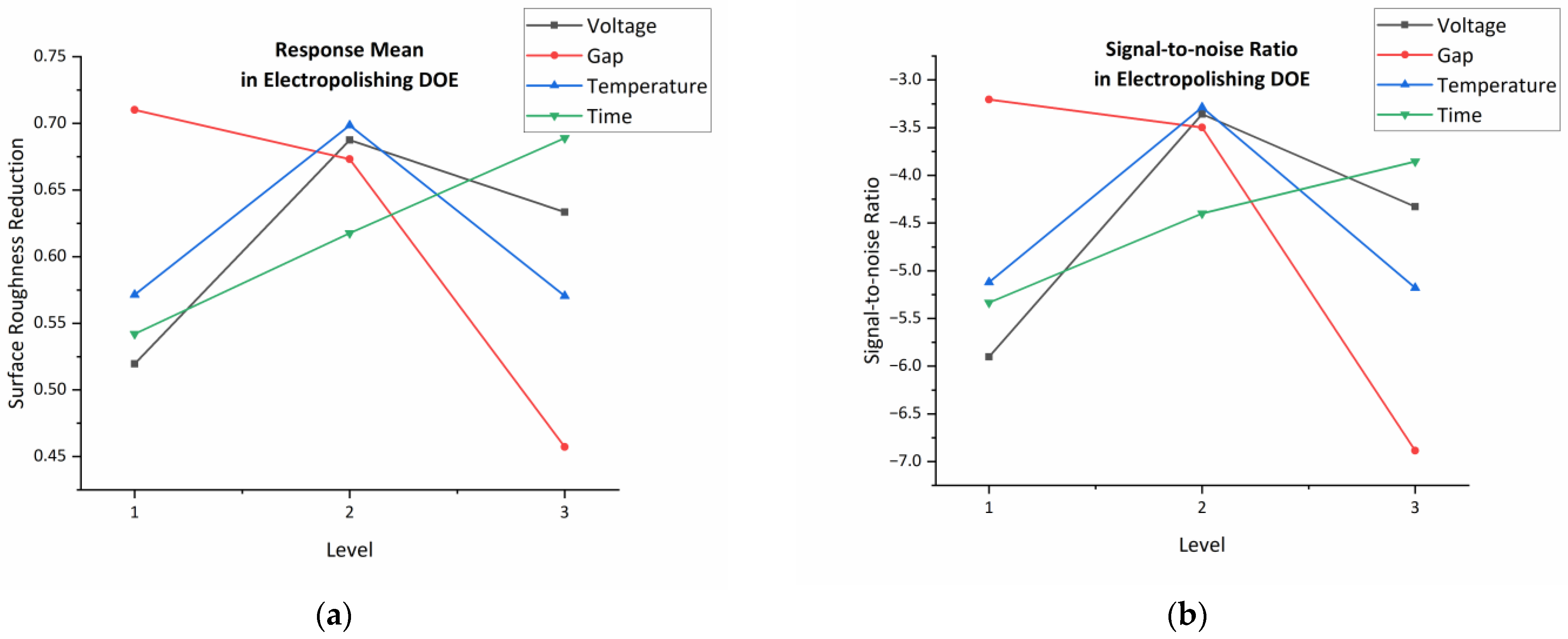
Since the goal of the experiment is to reduce the surface roughness of printed coupons, surface roughness reduction (ΔSa%) as calculated in Equation (1) was set as the response for data analysis, where Sa0 is the initial roughness and Saf is the final roughness. To analyze a Taguchi orthogonal array design, signal-to-noise (S/N) ratios calculated in Equation (2) following a the-larger-the-better standard were used for evaluating the process performance.
The Taguchi orthogonal array listed in Table 1 was analyzed based on the mean value for the surface roughness reduction and signal-to-noise ratio, as shown in Figure 6a,b. According to the results, in the three-level Taguchi design, when the voltage is 30 V, the temperature is 40 °C, the inter-electrode gap is 5 mm, and the polishing time is 45 min, the largest S/N ratio and the largest mean for surface roughness reduction can be achieved. Therefore, these parameters were selected to conduct further hybrid treatment. Figure 7 presents 3D surface images achieved by a Keyence laser profilometer after nine treatments.
Among all the tested influencing parameters, electrical voltage or the corresponding current density is the most significant influencing parameter for optimizing electropolishing performance. As described before, a low current density results in direct dissolution, while a high current density might lead to pit formation. If the voltage is lower than the optimal working voltage, the ionic mass transfer rate is higher than the anodic dissolution rate, and the polishing and leveling effect cannot be achieved. If the voltage is too high, excessive heat would be generated in the electrolyte, resulting in rapid metal dissolution and vigorous gas evolution, which leads to the accelerated formation of pitting corrosion and expeditious decomposition of the electrolyte solution.
The inter-electrode gap is another significant parameter. When the distance between the cathode and anode is large, the current generated in the electrolyte is not large enough, due to the large electrolyte resistance; thus, achieving the desired polishing effect is difficult. Therefore, the inter-electrode distance should be small enough to achieve enough current density and improved electropolishing efficiency. However, if the distance is too small, high local current density will lead to a rapid increase in electrolyte temperature, which may cause detrimental effects on the metal surface [38]. Electropolishing performance also increases with the temperature since the temperature increase helps accelerate the diffusion and migration of dissolved ions in the electrolyte. However, when the temperature reaches a certain point, electropolishing performance drops when the temperature further increases, due to the fact that etching pits may form on the surface at elevated temperatures. Moreover, surface roughness decreases with time in the feasible time range.
3.4. Effect of Ultrasound and Abrasion on Surface Finishing
In order to study the combined effect of ultrasonic vibration and abrasion on the surface roughness reduction, a surface roughness evolution curve was obtained after conducting the sole process for 8 h, as shown in Figure 8. The figure shows that the surface roughness of the part decreases rapidly in the first two hours and then becomes relatively stable afterward. Figure 9 presents and compares 3D images of the as-built part surface (Figure 9a) and the surface after 1 h (Figure 9b) and 4 h (Figure 9c) of treatment. While some partially melted powders can be removed from the metal surface, only 27% of surface roughness reduction was achieved. Due to the fact that no satisfying result was achieved from this method during the screening phase, no complete DOE was designed and conducted for this process. According to the preliminary results, ultrasound and abrasion alone do not have the capability to effectively reduce the surface roughness of the AM metal parts. However, when combining these with electrochemical surface finishing, synergistic effects are induced, improving the surface quality and the process efficiency at the same time.
3.5. Analysis of Hybrid Finishing Technique
Figure 10a,b show the main effect plots for response means and for S/N ratios when analyzing the surface roughness for the hybrid DOE as shown in Table 2. According to the results, in the three-level Taguchi design, when the process time is 45 min, the ultrasonic amplitude is 80%, and the abrasive concentration is 10%, the largest S/N ratio and the largest mean for surface roughness reduction can be achieved. However, the influence of ultrasonic amplitude and abrasive concentration is less significant than processing time in the selected parameter range. Figure 11 presents 3D surface images achieved by a Keyence laser profilometer after nine treatments.
Similar to electrochemical polishing, processing time is an important influencing factor for the hybrid finishing process. If the finishing time is too short, it is not adequate to generate effective polishing footprints on the part surface. The results show that hybrid finishing is able to decrease the Sa value of the part surface to ~1.02 μm after 45 min. Both ultrasonic amplitude and abrasive concentration have a slight impact on the Sa reduction. If the ultrasonic amplitude is not high enough, the vibration might not be substantially large for accelerating abrasive particles in the slurry, resulting in a low material removal efficiency. In addition, it is challenging for low-amplitude ultrasound waves to provide enough power to ensure uniform ionic mass transport for electrochemical polishing. However, a high ultrasonic amplitude may generate a huge amount of localized heat, causing damage to the metal surface while making it difficult to control the electrolyte temperature. If the abrasive concentration in the slurry is too low, the lack of abrasive particles in the slurry might not initiate obvious abrasion and peening on the surface for changing the surface condition. However, if the concentration is too high, abrasive particles could be embedded in the part surface, which might lead to a further increase in surface roughness. Meanwhile, the addition of abrasive particles in the electrolyte slurry also increases its viscosity while decreasing its conductivity [39,40], leading to the deterioration in the electropolishing performance.
3.6. Comparison between Electropolished Surface and Hybrid Finished Surface
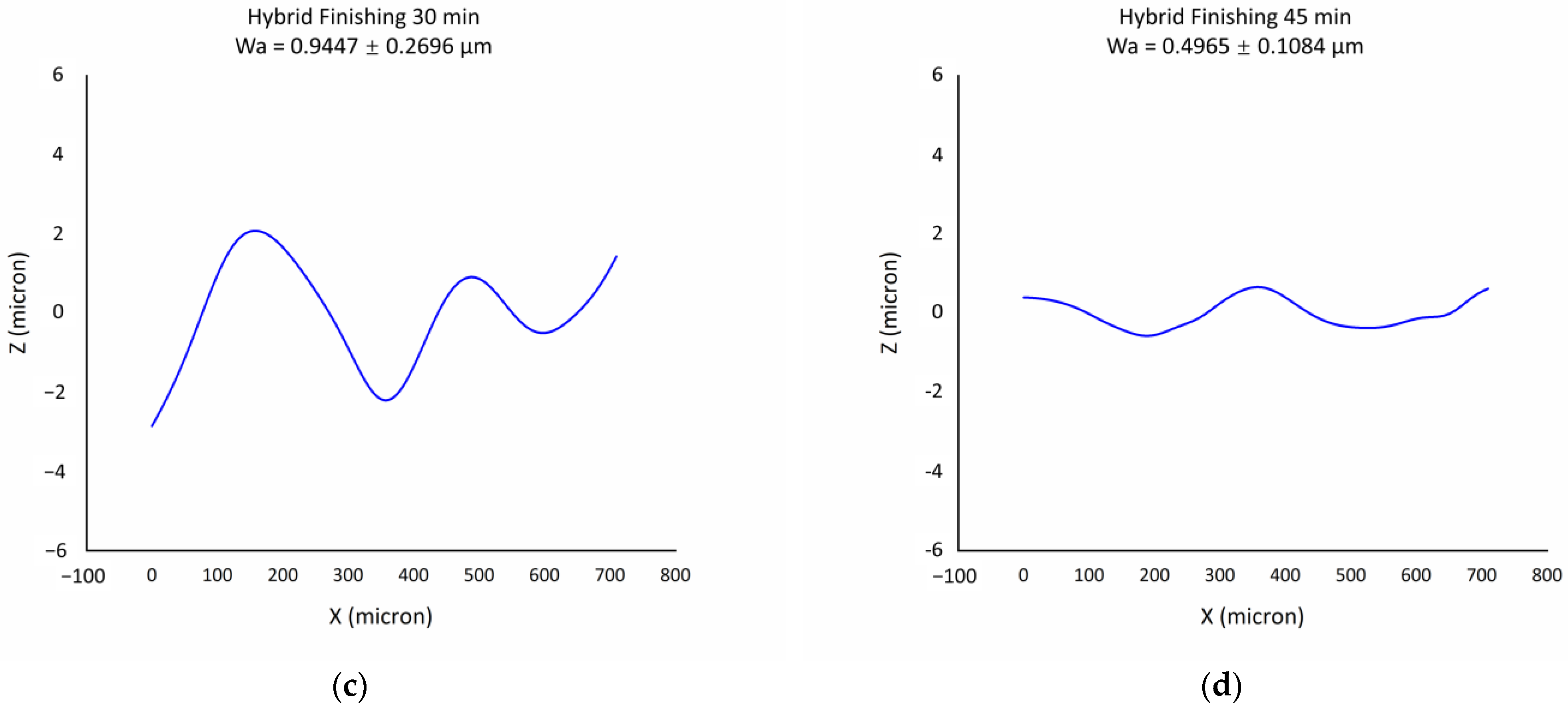
To analyze surface waviness, a waviness filter was applied to the line profile to extract large-scale surface waviness while eliminating the small-scale roughness signal. Figure 12 shows surface waviness profiles after electropolishing and hybrid finishing under optimal working parameters for different processing times as shown in Table 3. Increasing the finishing time from 30 min to 45 min for electropolishing and hybrid finishing decreases the surface waviness by 66.5% and 47.4%, respectively. Compared with electropolishing, hybrid finishing has the capability to provide a surface with a similar surface waviness in a shorter time, with the average Wa value of 0.83 μm after electropolishing for 45 min, while the same value is 0.94 μm after hybrid finishing for 30 min. After process optimization for both processes, although similar Sa values are obtained, the surface waviness of hybrid technique-treated samples is much less than the electropolished samples, as presented in Figure 13.
4. Discussion
There are multiple causes of the large-scale surface waviness of electropolished metal AM parts, from the perspectives of both AM and electropolishing. The stair-stepping effect is a main type of surface irregularity for AM parts. It is created due to the layer-by-layer nature of the process, where a larger layer thickness may result in visible discontinuities on the part’s surface, resulting in large surface waviness. Although electropolishing could eliminate the small-scale surface roughness effectively, it seems not to be efficient enough to remove the surface waviness via merely electropolishing. From another perspective, the electropolishing process could introduce surface waviness as well due to non-uniform mass transfer. When there are localized concentration variations in the electrolyte flow, non-uniform distribution of the current density occurs, which would lead to uneven material dissolution and, consequently, the formation of surface waviness.
In the electropolishing process, a voltage is applied between the workpiece anode and the inert cathode; Ti atoms on the workpiece surface dissolve in the electrolyte by being oxidized to Ti4+ ions. In order to maintain the electrical neutrality of the electrolyte, Cl− ions in the bulk electrolyte migrate to the workpiece surface and complex with Ti4+ to form TiCl4. TiCl4 is a viscous liquid, which forms a viscous layer with a higher electrical resistivity compared to the bulk electrolyte adjacent to the workpiece anode. According to the viscous film theory [21], due to the high surface roughness of the as-built workpiece, the thickness of the viscous layer at the valley is higher than the thickness at the peak. Accordingly, the viscous layer at the valley has larger electrical resistance compared with the viscous layer at the peak, resulting in a potential difference at different surface locations, leading to a leveling and polishing effect. With the progress of the aforementioned process, the surface roughness as well as the surface waviness decreases with time, while the uniformity of the waviness distribution also increases. Although electropolishing has the capability to reduce the surface roughness and waviness, when the processing time reaches the threshold limit, instead of polishing the surface and further reducing the surface waviness, overpolishing occurs with pits forming on the surface. The mechanism is shown in Figure 14.
While electropolishing plays the main role in material removal, abrasive particles accelerated by the ultrasonic cavitation help reduce the surface roughness by cutting and peening, also as shown in Figure 14. When ultrasonic energy is applied to the liquid medium, the pressure of the ultrasound wave vibrates under the ultrasound frequency. A reduction in the liquid’s static pressure to below its vapor pressure leads to the formation and growth of cavities or “gas bubbles”, which would collapse when the pressure inside the bubble increases and reaches the threshold pressure. When adding abrasive particles into the liquid medium, cavitation bubble collapse accelerates the abrasive particles in the slurry, leading to the impact of abrasive particles on the metal surface, which generates abrasive erosion on the metal surface.
The high initial kinetic energy of abrasive particles could be achieved due to the formation of a shockwave and micro-jet in the ultrasonic cavitation, which has been verified by numerical simulations [41]. When abrasive particles impact the metal surface, material removal with different patterns happens under different impact angles. When the particle impacts the metal surface with a shallow impact angle, cutting acts as the main mechanism, as shown in Figure 15a. Abrasive particles with high initial speed cut the surface bumps and lead to the reduction in surface waviness. On the other hand, if the impact angle is large, or the abrasive particles vertically impact the surface bumps, peening instead of cutting occurs on the metal surface, which creates localized plastic deformation and may possibly benefit with a reduction in surface roughness (Figure 15b). At the same time, the ultrasonic cavitation itself might also contribute to the roughness and waviness reduction to some extent (Figure 15c). When the gas bubbles form and grow close to the surface protrusions, high shear stress could be generated due to bubble collapse, leading to crack propagation on the surface bumps and eventually resulting in material removal.
In addition to the aforementioned mechanisms for reducing surface roughness, we propose another possible mechanism for the hybrid finishing technique to mitigate surface waviness, attributed to the synergistic effect of electropolishing, ultrasound, and abrasives. Given that solid surfaces in the liquid electrolyte solution are the preferred sites for cavitation to occur, the localized bubble density near the metal surface may be higher than in other areas of the bulk electrolyte during treatment. Moreover, bubbles and abrasives situated at the wave trough are less likely to move freely, potentially resulting in higher concentrations of abrasive particles and cavitation bubbles at the metal surface compared to the bulk electrolyte, as shown in Figure 16. The presence of a higher concentration of particles at the wave trough increases the viscosity in this region, maybe leading to a decrease in ionic conductivity compared to the wave crest. Consequently, the application of ultrasound and abrasive particles may generate a “synthetic viscous layer” at the metal surface on a larger scale, adjusting the localized ionic conductivity of the electrolyte during the electropolishing process and thus reducing surface waviness.
Although the experimental results in this study are achieved on the rectangular coupons, this method is also a promising candidate for surface finishing of curved and conformal surfaces, and other types of external surfaces with complicated geometries, which cannot be achieved by conventional grinding and cutting. Figure 17 shows the pictures of the cylinder surface after the hybrid process. Due to its capability of polishing curved surfaces, the proposed method has the potential for various applications, such as surface finishing of printed implants for biomedical applications and reducing the roughness of engine components for the automotive or aerospace and aviation sectors. The next step of this study will be to adjust the method for improving the surface quality of internal channels, which will be beneficial for heat exchangers and conformal cooling passages for energy applications.
5. Conclusions
In this research, an experimental feasibility study was carried out to shed some light on the general concept of the novel hybrid ultrasound abrasive-driven electrochemical surface finishing method. The preliminary results prove the feasibility of the idea. To synergistically study the effect of different processes involved, electropolishing, ultrasound/abrasion, and hybrid surface finishing were conducted on the LPBF-made Ti6Al4V coupons when the resultant surface roughness was compared. The conclusions are as follows:
- (1)
- A smooth and reflective surface could be achieved after both the electropolishing and hybrid treatment, with the optimal Sa values of 1.36 ± 0.21 µm and 1.02 ± 0.45 µm, respectively.
- (2)
- No evidence showed that the combination of ultrasound and abrasion is capable of effectively reducing surface roughness.
- (3)
- The introduction of ultrasound and abrasion into electropolishing has the capability to reduce the surface waviness further compared to electropolishing, with the Wa value being 0.83 ± 0.40 µm for electropolishing and 0.50 ± 0.11 µm for hybrid finishing after 45 min.
Although the hybrid treatment shows promising potential for surface finishing of AM parts, temperature control remains a challenge in terms of scaling it up due to the rapid heat generation when introducing ultrasound and abrasion into electrochemical surface finishing. In addition, process optimization for finishing complex parts with internal channels is another challenge that needs to be solved.
Author Contributions
Conceptualization, M.S. and E.T.; methodology, M.S. and E.T.; formal analysis, M.S.; investigation, M.S.; resources, M.S.; data curation, M.S.; writing—original draft preparation, M.S.; writing—review and editing, E.T.; visualization, M.S.; supervision, E.T.; project administration, E.T.; funding acquisition, E.T. All authors have read and agreed to the published version of the manuscript.
Funding
This research was funded by the Natural Sciences and Engineering Research Council of Canada (NSERC), grant number RGPIN-2020-06306.
Data Availability Statement
The data used to support the findings of this study are available from the corresponding author upon request.
Acknowledgments
The authors gratefully acknowledge Jerry Ratthapakdee in MSAM UWaterloo for printing the samples used for the study.
Conflicts of Interest
The authors declare no conflicts of interest.
References
- Toyserkani, E.; Sarker, D.; Ibhadode, O.O.; Liravi, F.; Russo, P.; Taherkhani, K. Metal Additive Manufacturing; Wiley: Hoboken, NJ, USA, 2022; pp. 330–337. [Google Scholar] [CrossRef]
- Casalino, G.; Karamimoghadam, M.; Contuzzi, N. Metal Wire Additive Manufacturing: A Comparison between Arc Laser and Laser/Arc Heat Sources. Inventions 2023, 8, 52. [Google Scholar] [CrossRef]
- Snyder, J.C.; Thole, K.A. Understanding Laser Powder Bed Fusion Surface Roughness. J. Manuf. Sci. Eng. 2020, 142, 071003. [Google Scholar] [CrossRef]
- Hassanin, H.; Elshaer, A.; Benhadj-Djilali, R.; Modica, F.; Fassi, I. Surface Finish Improvement of Additive Manufactured Metal Parts. In Micro and Precision Manufacturing; Engineering Materials; Gupta, K., Ed.; Springer: Cham, Switzerland, 2018; pp. 145–164. [Google Scholar] [CrossRef]
- Sanaei, N.; Fatemi, A. Analysis of the Effect of Surface Roughness on Fatigue Performance of Powder Bed Fusion Additive Manufactured Metals. Theor. Appl. Fract. Mech. 2020, 108, 102638. [Google Scholar] [CrossRef]
- Toloei, A.; Stoilov, V.; Northwood, D. The Relationship between Surface Roughness and Corrosion. In Proceedings of the ASME International Mechanical Engineering Congress and Exposition (IMECE), San Diego, CA, USA, 15–21 November 2013. [Google Scholar] [CrossRef]
- Beaucamp, A.T.; Namba, Y.; Charlton, P.; Jain, S.; Graziano, A.A. Finishing of Additively Manufactured Titanium Alloy by Shape Adaptive Grinding (SAG). Surf. Topogr. Metrol. Prop. 2015, 3, 024001. [Google Scholar] [CrossRef]
- Bagehorn, S.; Wehr, J.; Maier, H.J. Application of Mechanical Surface Finishing Processes for Roughness Reduction and Fatigue Improvement of Additively Manufactured Ti-6Al-4V Parts. Int. J. Fatigue 2017, 102, 135–142. [Google Scholar] [CrossRef]
- AlMangour, B.; Yang, J.M. Integration of Heat Treatment with Shot Peening of 17-4 Stainless Steel Fabricated by Direct Metal Laser Sintering. JOM 2017, 69, 2309–2313. [Google Scholar] [CrossRef]
- Lee, J.Y.; Nagalingam, A.P.; Yeo, S.H. A Review on the State-of-the-Art of Surface Finishing Processes and Related ISO/ASTM Standards for Metal Additive Manufactured Components. Virtual Phys. Prototyp. 2021, 16, 68–96. [Google Scholar] [CrossRef]
- Sunay, N.; Kaya, M.; Kaynak, Y. Chemical Post-Processing Methods for Enhancing Surface Properties of Parts Fabricated by Additive Manufacturing: A Review. Sigma J. Eng. Nat. Sci. 2020, 38, 2027–2042. [Google Scholar]
- Bezuidenhout, M.; Haar, G.T.; Becker, T.; Rudolph, S.; Damm, O.; Sacks, N. The Effect of HF-HNO3 Chemical Polishing on the Surface Roughness and Fatigue Life of Laser Powder Bed Fusion Produced Ti6Al4V. Mater. Today Commun. 2020, 25, 101396. [Google Scholar] [CrossRef]
- Urlea, V.; Brailovski, V. Electropolishing and Electropolishing-related Allowances for IN625 Alloy Components Fabricated by Laser Powder-Bed Fusion. Int. J. Adv. Manuf. Technol. 2017, 92, 4487–4499. [Google Scholar] [CrossRef]
- Maleki, E.; Bagherifard, S.; Bandini, M.; Guagliano, M. Surface Post-Treatments for Metal Additive Manufacturing: Progress, Challenges, and Opportunities. Addit. Manuf. 2021, 37, 101619. [Google Scholar] [CrossRef]
- Dixit, N.; Sharma, V.; Kumar, P. Research Trends in Abrasive Flow Machining: A Systematic Review. J. Manuf. Process. 2021, 64, 1434–1461. [Google Scholar] [CrossRef]
- Peng, C.; Fu, Y.; Wei, H.; Li, S.; Wang, X.; Gao, H. Study on Improvement of Surface Roughness and Induced Residual Stress for Additively Manufactured Metal Parts by Abrasive Flow Machining. Procedia CIRP 2018, 71, 386–389. [Google Scholar] [CrossRef]
- François, M.; Han, S.; Segonds, F.; Dupuy, C.; Rivette, M.; Turpault, S.; Mimouna, M.; Salvatore, F.; Rech, J.; Peyre, P. Electromagnetic Performance of Ti6Al4V and AlSi7Mg0.6 Waveguides with Laser Beam Melting (LBM) Produced and Abrasive Flow Machining (AFM) Finished Internal Surfaces. J. Electromagn. Waves Appl. 2021, 35, 2510–2526. [Google Scholar] [CrossRef]
- Qian, C.; Fan, Z.; Tian, Y.; Liu, Y.; Han, J.; Wang, J. A Review on Magnetic Abrasive Finishing. Int. J. Adv. Manuf. Technol. 2021, 112, 619–634. [Google Scholar] [CrossRef]
- Zhu, P.; Zhang, G.; Teng, X.; Du, J.; Jiang, L.; Chen, H.; Liu, N. Investigation and Process Optimization for Magnetic Abrasive Finishing Additive Manufacturing Samples with Different Forming Angles. Int. J. Adv. Manuf. Technol. 2022, 118, 2355–2371. [Google Scholar] [CrossRef]
- Lee, S.; Ahmadi, Z.; Pegues, J.W.; Mahjouri-Samani, M.; Shamsaei, N. Laser Polishing for Improving Fatigue Performance of Additive Manufactured Ti-6Al-4V Parts. Opt. Laser Technol. 2021, 134, 106639. [Google Scholar] [CrossRef]
- Han, W.; Fang, F. Fundamental Aspects and Recent Developments in Electropolishing. Int. J. Mach. Tools Manuf. 2019, 139, 1–23. [Google Scholar] [CrossRef]
- Tyagi, P.; Goulet, T.; Riso, C.; Stephenson, R.; Chuenprateep, N.; Schlitzer, J.; Benton, C.; Garcia-Moreno, F. Reducing the Roughness of Internal Surface of an Additive Manufacturing Produced 316 Steel Component by Chempolishing and Electropolishing. Addit. Manuf. 2019, 25, 32–38. [Google Scholar] [CrossRef]
- Acquesta, A.; Monetta, T. The Electropolishing of Additively Manufactured Parts in Titanium: State of the Art. Adv. Eng. Mater. 2021, 23, 2100545. [Google Scholar] [CrossRef]
- Mingear, J.; Zhang, B.; Hartl, D.; Elwany, A. Effect of Process Parameters and Electropolishing on the Surface Roughness of Interior Channels in Additively Manufactured Nickel-Titanium Shape Memory Alloy Actuators. Addit. Manuf. 2019, 27, 565–575. [Google Scholar] [CrossRef]
- Mohammadian, N.; Turenne, S.; Brailovski, V. Electropolishing of Laser Powder Bed-Fused IN625 Components in an Ionic Electrolyte. J. Manuf. Mater. Process. 2019, 3, 86. [Google Scholar] [CrossRef]
- Jain, S.; Corliss, M.; Tai, B.; Hung, W.N. Electrochemical Polishing of Selective Laser Melted Inconel 718. Procedia Manuf. 2019, 34, 239–246. [Google Scholar] [CrossRef]
- Ali, U.; Fayazfar, H.; Ahmed, F.; Toyserkani, E. Internal Surface Roughness Enhancement of Parts Made by Laser Powder-Bed Fusion Additive Manufacturing. Vacuum 2020, 177, 109314. [Google Scholar] [CrossRef]
- Zhang, Y.; Li, J.; Che, S.; Tian, Y. Electrochemical Polishing of Additively Manufactured Ti–6Al–4V Alloy. Met. Mater. Int. 2020, 26, 783–792. [Google Scholar] [CrossRef]
- Alrbaey, K.; Wimpenny, D.I.; Al-Barzinjy, A.A.; Moroz, A. Electropolishing of Re-Melted SLM Stainless Steel 316L Parts Using Deep Eutectic Solvents: 3 × 3 Full Factorial Design. J. Mater. Eng. Perform. 2016, 25, 2836–2846. [Google Scholar] [CrossRef]
- Zhao, C.; Qu, N.; Tang, X. Electrochemical Mechanical Polishing of Internal Holes Created by Selective Laser Melting. J. Manuf. Process. 2021, 64, 1544–1562. [Google Scholar] [CrossRef]
- Rech, J.; Krzak, D.; Roy, F.; Salvatore, F.; Gidon, A.; Guérin, S. A New Hybrid Electrochemical-Mechanical Process (PEMEC) for Polishing Complex and Rough Parts. CIRP Ann. 2022, 71, 173–176. [Google Scholar] [CrossRef]
- Liu, S.; Shin, Y.C. Additive Manufacturing of Ti6Al4V Alloy: A Review. Mater. Des. 2019, 164, 107552. [Google Scholar] [CrossRef]
- Fayazfar, H.; Rishmawi, I.; Vlasea, M. Electrochemical-Based Surface Enhancement of Additively Manufactured Ti-6Al-4V Complex Structures. J. Mater. Eng. Perform. 2021, 30, 2245–2255. [Google Scholar] [CrossRef]
- Aver’yanova, I.; Bogomolov, D.; Poroshin, V. ISO 25178 Standard for Three-Dimensional Parametric Assessment of Surface Texture. Russ. Eng. Res. 2017, 37, 513–516. [Google Scholar] [CrossRef]
- Carter, L.N.; Villapún, V.M.; Grover, L.; Cox, S.C. Exploring the Duality of Powder Adhesion and Underlying Surface Roughness in Laser Powder Bed Fusion Processed Ti-6Al-4V. J. Manuf. Process. 2022, 81, 14–26. [Google Scholar] [CrossRef]
- Gu, D.; Shen, Y. Balling Phenomena in Direct Laser Sintering of Stainless Steel Powder: Metallurgical Mechanisms and Control Methods. Mater. Des. 2009, 30, 2903–2910. [Google Scholar] [CrossRef]
- Jacquet, P.A. Electrolytic Polishing of Metallic Surfaces. Met. Finish. 1949, 47, 48–54. [Google Scholar]
- Wang, G.; Liu, Z.; Niu, J.; Huang, W.; Wang, B. Effect of Electrochemical Polishing on Surface Quality of Nickel-Titanium Shape Memory Alloy after Milling. J. Mater. Res. Technol. 2020, 9, 253–262. [Google Scholar] [CrossRef]
- Su, K.; Wu, J.; Xia, D. Dual Role of Microparticles in Synergistic Cavitation–Particle Erosion: Modeling and Experiments. Wear 2021, 470–471, 203633. [Google Scholar] [CrossRef]
- Szwajczakaf, E.; Szymański, A. On the Relation Between Mobility of lons and Viscosity. The Walden’s Rule. Mol. Cryst. Liq. Cryst. 1986, 139, 253–261. [Google Scholar] [CrossRef]
- Fu, Y.; Zhu, X.; Wang, J.; Gong, T. Numerical Study of the Synergistic Effect of Cavitation and Micro-Abrasive Particles. Ultrason. Sonochem. 2022, 89, 106119. [Google Scholar] [CrossRef]
Figure 1.
Schematic of experiment setup for (a) electropolishing, (b) surface finishing with ultrasound and abrasion, and (c) ultrasound abrasive-driven electrochemical hybrid finishing.
Figure 1.
Schematic of experiment setup for (a) electropolishing, (b) surface finishing with ultrasound and abrasion, and (c) ultrasound abrasive-driven electrochemical hybrid finishing.

Figure 2.
Locations of surface roughness and surface waviness measurements.
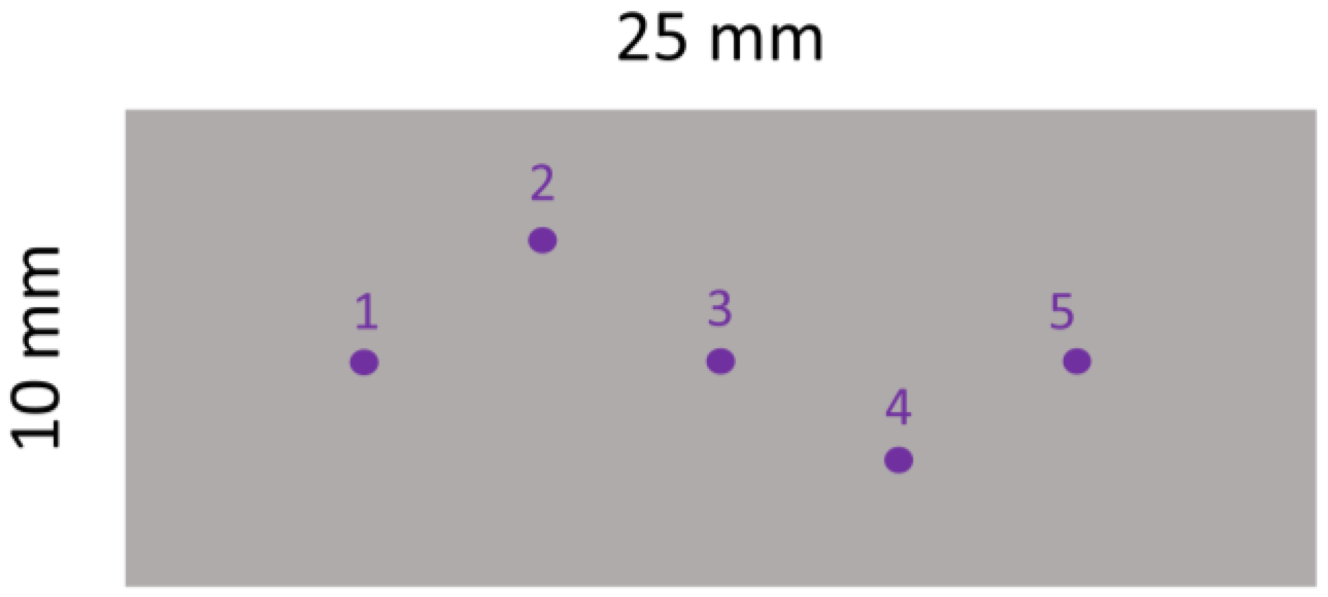
Figure 3.
Images of as-built coupons: (a) camera image; (b) 3D height profile; (c) laser optical surface image.
Figure 3.
Images of as-built coupons: (a) camera image; (b) 3D height profile; (c) laser optical surface image.

Figure 4.
SEM images of as-built surface (a) 200×; (b) 1000×.
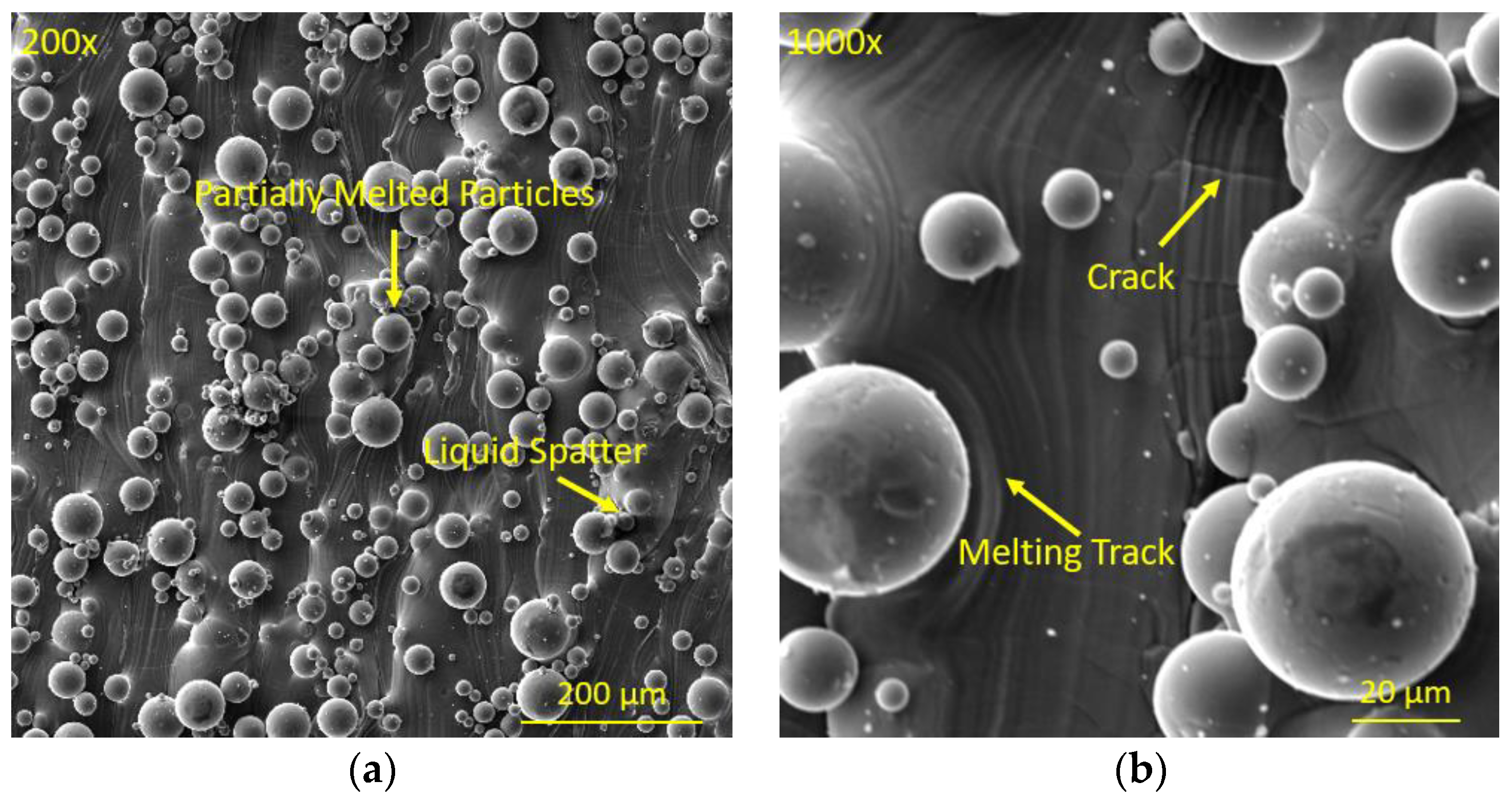
Figure 5.
Polarization curve in electropolishing (a) redrawn and adapted from [21]; (b) achieved from experiment.
Figure 5.
Polarization curve in electropolishing (a) redrawn and adapted from [21]; (b) achieved from experiment.
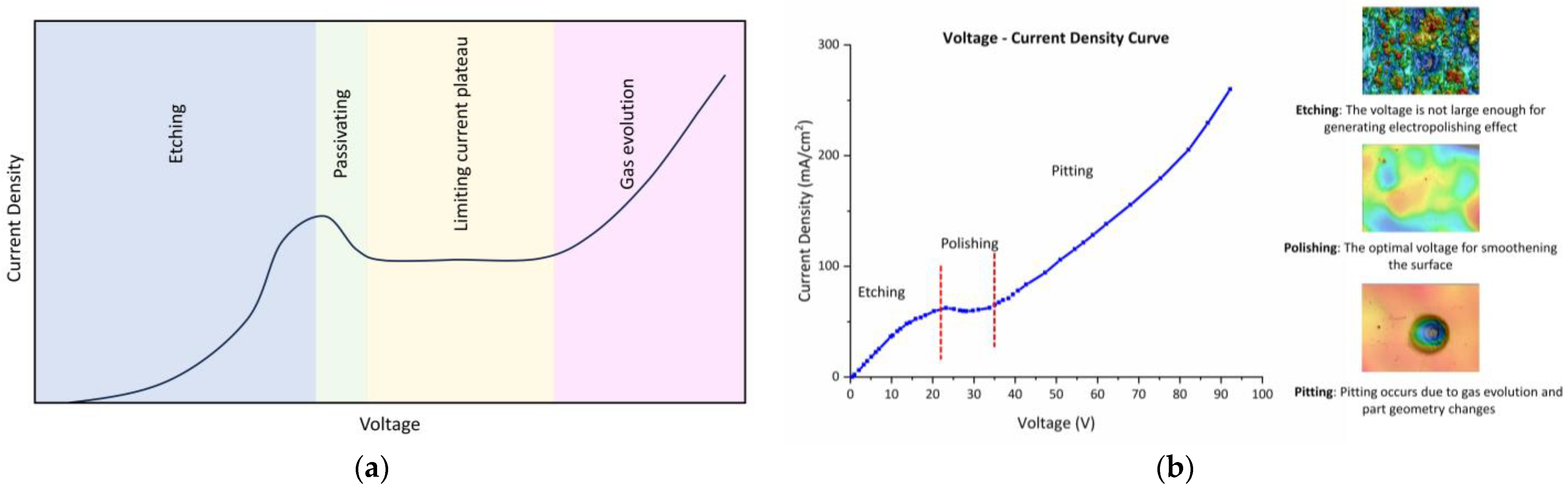
Figure 6.
Main effect plots in electropolishing DOE for (a) response means and (b) S/N ratios.

Figure 7.
Three-dimensional surface images for samples in electropolishing DOE.
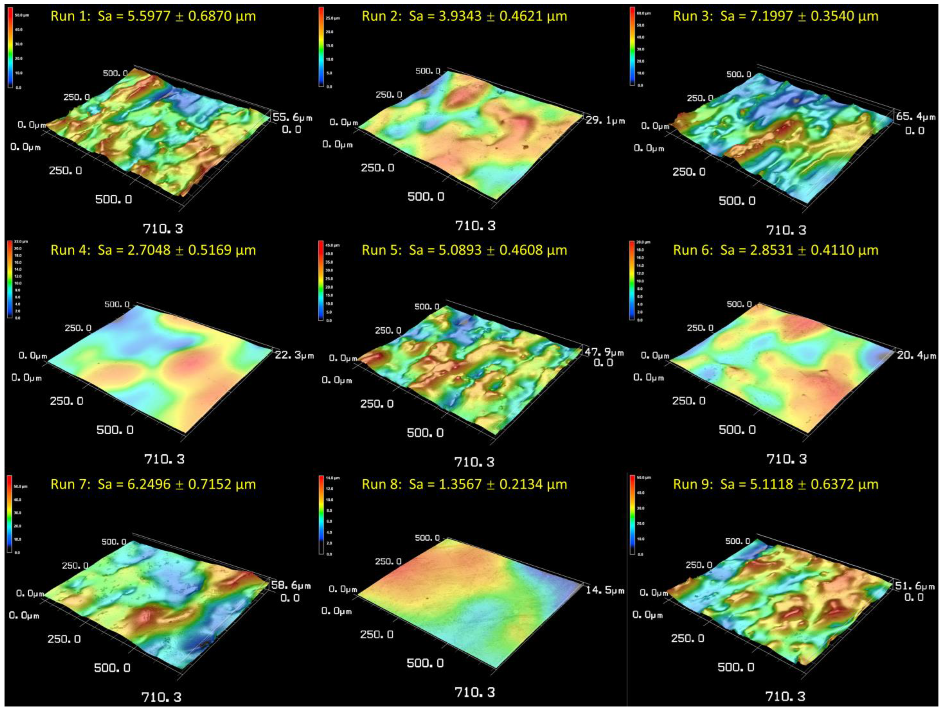
Figure 8.
Surface roughness evolution with time under ultrasound and abrasion.
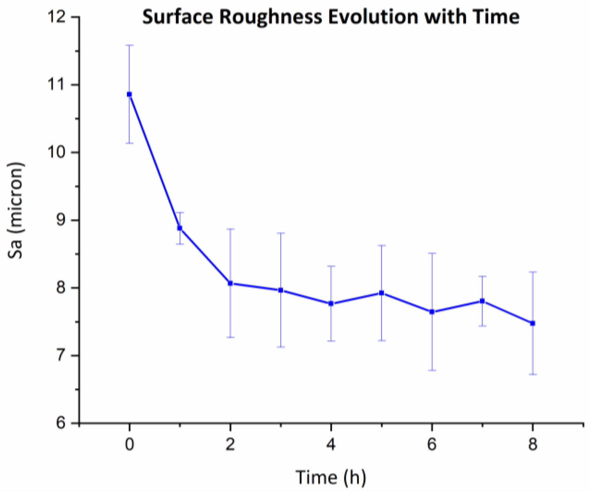
Figure 9.
Three-dimensional images of (a) as-built surface; (b) surface after 1 h treatment by ultrasound and abrasion; and (c) surface after 4 h treatment by ultrasound and abrasion.
Figure 9.
Three-dimensional images of (a) as-built surface; (b) surface after 1 h treatment by ultrasound and abrasion; and (c) surface after 4 h treatment by ultrasound and abrasion.

Figure 10.
Main effect plots in hybrid DOE for (a) response means and (b) S/N ratios.

Figure 11.
Three-dimensional surface images for samples in hybrid DOE.
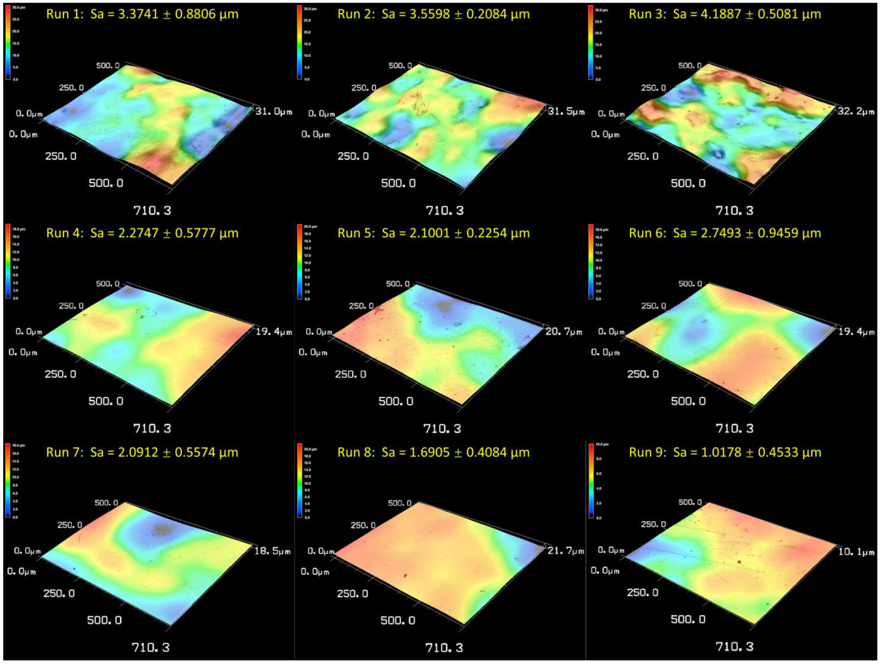
Figure 12.
Surface waviness profile for (a) electropolishing for 30 min; (b) electropolishing for 45 min; (c) hybrid finishing for 30 min; (d) hybrid finishing for 45 min.
Figure 12.
Surface waviness profile for (a) electropolishing for 30 min; (b) electropolishing for 45 min; (c) hybrid finishing for 30 min; (d) hybrid finishing for 45 min.
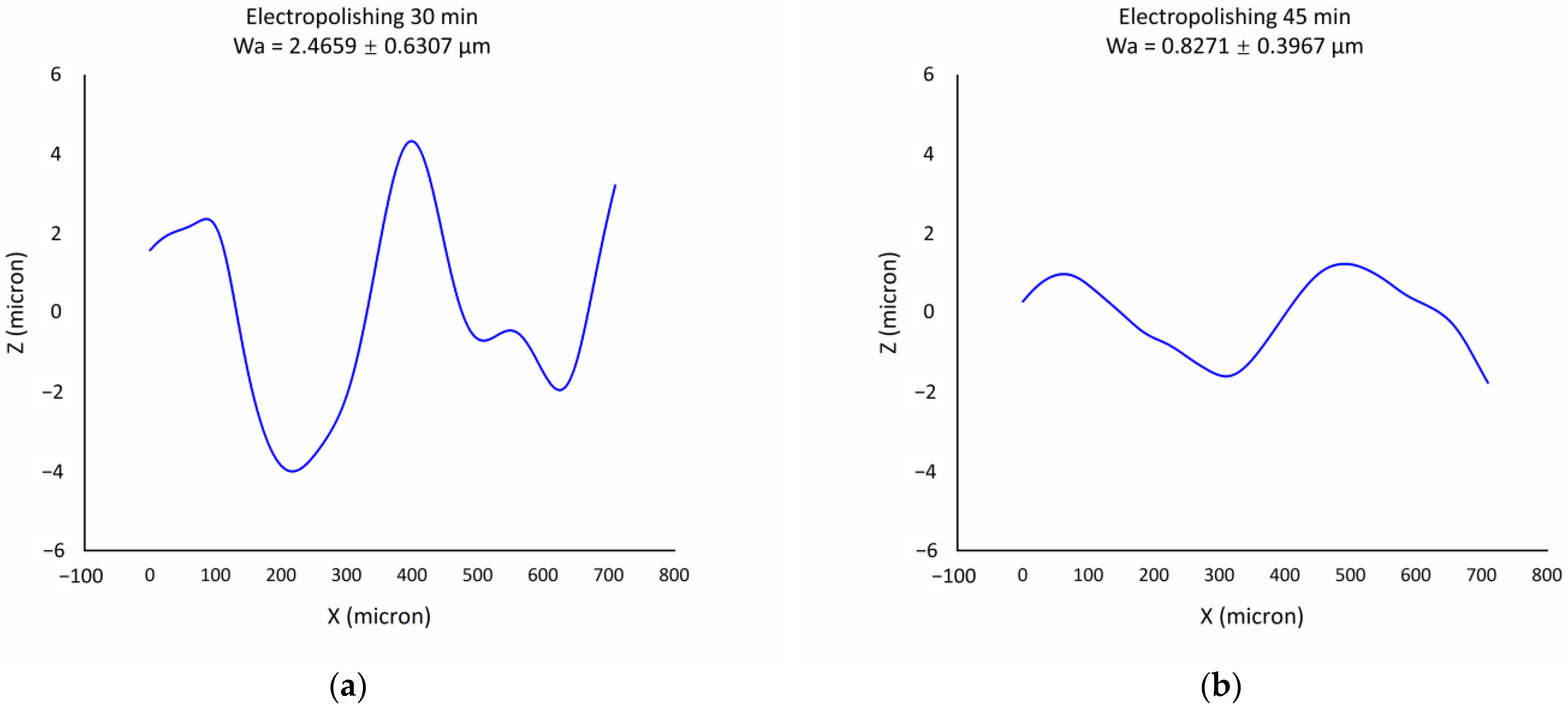

Figure 13.
Surface roughness and waviness comparison for electropolishing and hybrid finishing.

Figure 14.
Surface finishing mechanism for electropolishing and hybrid finishing.
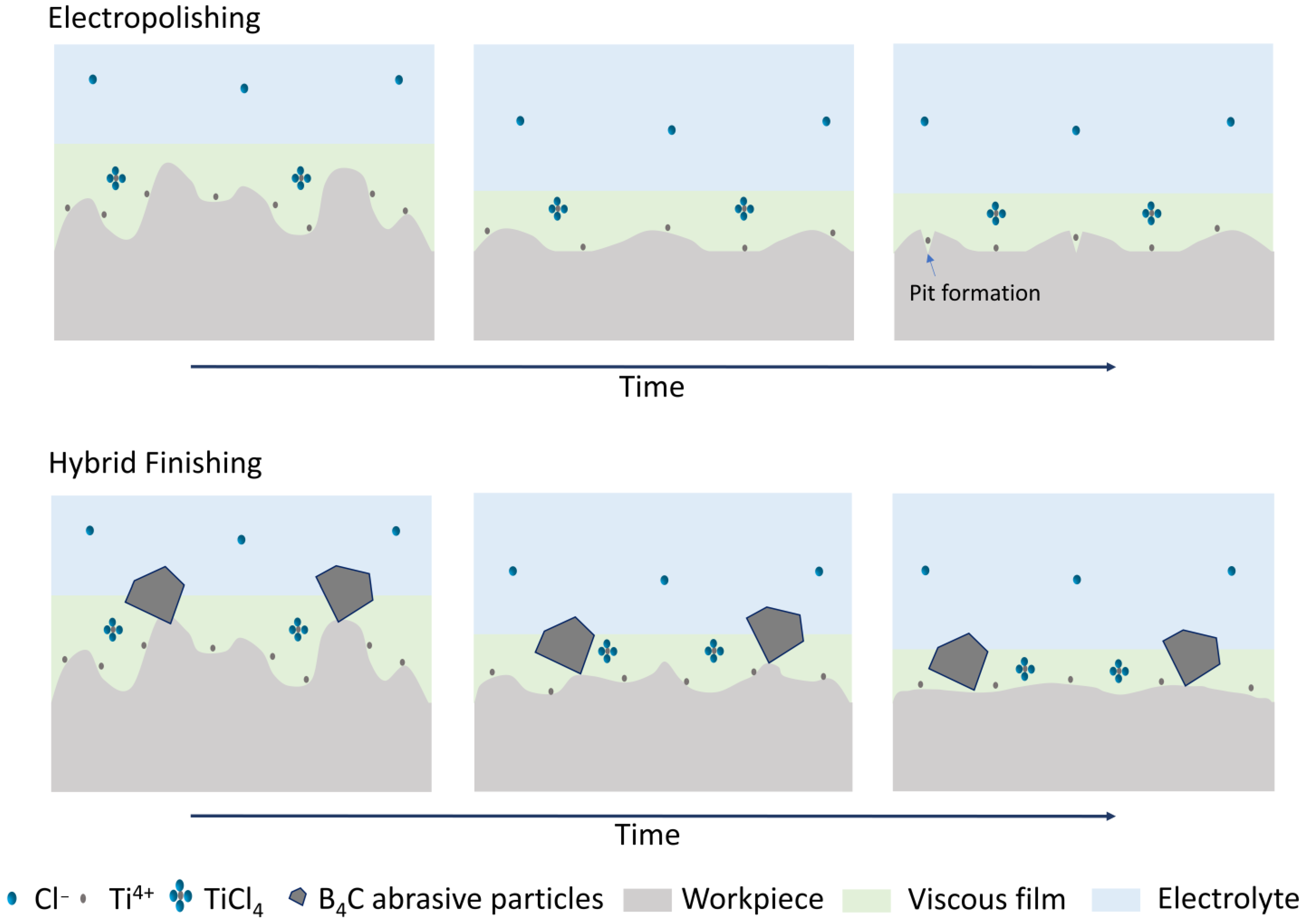
Figure 15.
Mechanism for roughness removal due to ultrasound and abrasion: (a) cutting due to shallow impact angle; (b) peening due to large impact angle; (c) micro-void formation and material removal due to cavitation bubble collapse.
Figure 15.
Mechanism for roughness removal due to ultrasound and abrasion: (a) cutting due to shallow impact angle; (b) peening due to large impact angle; (c) micro-void formation and material removal due to cavitation bubble collapse.

Figure 16.
Hypothesis for waviness removal due to synergistic effect of electropolishing, and application of ultrasound and abrasive particles.
Figure 16.
Hypothesis for waviness removal due to synergistic effect of electropolishing, and application of ultrasound and abrasive particles.

Figure 17.
(a) Camera picture of as-built cylinder surface; (b) camera picture of cylinder surface after hybrid finishing.
Figure 17.
(a) Camera picture of as-built cylinder surface; (b) camera picture of cylinder surface after hybrid finishing.


Table 1.
Taguchi L9 design for electropolishing DOE.
| Run | Voltage (V) | Temperature (°C) | Gap (mm) | Time (min) |
|---|---|---|---|---|
| 1 | 25 | 25 | 5 | 15 |
| 2 | 25 | 40 | 10 | 30 |
| 3 | 25 | 55 | 15 | 45 |
| 4 | 30 | 25 | 10 | 45 |
| 5 | 30 | 40 | 15 | 15 |
| 6 | 30 | 55 | 5 | 30 |
| 7 | 35 | 25 | 15 | 30 |
| 8 | 35 | 40 | 5 | 45 |
| 9 | 35 | 55 | 10 | 15 |
Table 2.
Taguchi L9 design for hybrid DOE.
| Run | Time (min) | Ultrasonic Amplitude (%) | Abrasive Concentration (%) |
|---|---|---|---|
| 1 | 15 | 70 | 5 |
| 2 | 15 | 80 | 10 |
| 3 | 15 | 90 | 15 |
| 4 | 30 | 70 | 10 |
| 5 | 30 | 80 | 15 |
| 6 | 30 | 90 | 5 |
| 7 | 45 | 70 | 15 |
| 8 | 45 | 80 | 5 |
| 9 | 45 | 90 | 10 |
Table 3.
Parameter selection for surface waviness investigation.
| Sample Name | Type of Treatment | Time | Other Parameters |
|---|---|---|---|
| E-30 | Electropolishing | 30 min | Voltage 30 V, Temperature 40 ± 3 °C, |
| E-45 | Electropolishing | 45 min | Inter-electrode gap 5 mm, |
| H-30 | Hybrid finishing | 30 min | Ultrasonic Amplitude 80%, |
| H-45 | Hybrid finishing | 45 min | Abrasive Concentration 10% |
Disclaimer/Publisher’s Note: The statements, opinions and data contained in all publications are solely those of the individual author(s) and contributor(s) and not of MDPI and/or the editor(s). MDPI and/or the editor(s) disclaim responsibility for any injury to people or property resulting from any ideas, methods, instructions or products referred to in the content. |
© 2024 by the authors. Licensee MDPI, Basel, Switzerland. This article is an open access article distributed under the terms and conditions of the Creative Commons Attribution (CC BY) license (https://creativecommons.org/licenses/by/4.0/).
Share and Cite
MDPI and ACS Style
Sun, M.; Toyserkani, E. A Novel Hybrid Ultrasound Abrasive-Driven Electrochemical Surface Finishing Technique for Additively Manufactured Ti6Al4V Parts. Inventions 2024, 9, 45. https://doi.org/10.3390/inventions9020045
AMA Style
Sun M, Toyserkani E. A Novel Hybrid Ultrasound Abrasive-Driven Electrochemical Surface Finishing Technique for Additively Manufactured Ti6Al4V Parts. Inventions. 2024; 9(2):45. https://doi.org/10.3390/inventions9020045
Chicago/Turabian StyleSun, Manyou, and Ehsan Toyserkani. 2024. "A Novel Hybrid Ultrasound Abrasive-Driven Electrochemical Surface Finishing Technique for Additively Manufactured Ti6Al4V Parts" Inventions 9, no. 2: 45. https://doi.org/10.3390/inventions9020045