Segmented Control of Electrostatically Actuated Bimorph Beams †

1
Air Force Institute of Technology, Wright-Patterson AFB, OH, USA
2
Sensors Directorate, Air Force Research Laboratory, Wright-Patterson AFB, OH, USA
*
Author to whom correspondence should be addressed.
†
Presented at the Eurosensors 2017 Conference, Paris, France, 3–6 September 2017.
Proceedings 2017, 1(4), 306; https://doi.org/10.3390/proceedings1040306
Published: 25 August 2017
(This article belongs to the Proceedings of Proceedings of Eurosensors 2017, Paris, France, 3–6 September 2017)
Abstract
:This research focused on improving the control and sensing of electrostatically actuated, large deflection bimorph beams for optical beam steering. Current iterations of designs utilize a ‘zipper’ beam and have demonstrated large deflection angles. However, with these devices precise control and deflection measurements can be difficult to achieve. Through using segmented bias channels of doped polysilicon, modeling shows it is possible to control and measure different segments of the actuation arm, thus controlling the amount of tip, tilt, or piston deflection. This paper discusses current and future designs, along with test procedures and modeling results.
1. Introduction
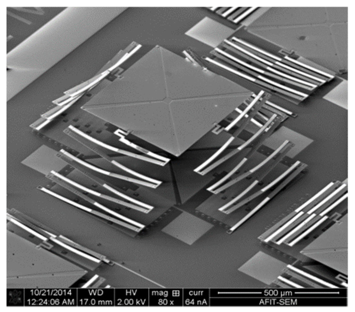
Micromirror arrays can be used for optical beam steering. Current iterations of micromirror array designs to improve fill-factor and increase deflection angle utilize four bimorph electrostatic actuating ‘zipper’ beams placed around a central platform. Residual stresses from the PolyMUMPs foundry process and the difference in the coefficients of thermal expansion (CTE) causes the bimorph beams to initially deflect up, out-of-plane. The device is actuated by creating a potential difference resulting in an electrostatic force between the zipper beams and the underlying electrode causing the beams to deflect down. As shown in Figure 1, the zipper approach allows a large vertical displacement of up to 175 μm to be achieved within a relatively small area [1]. The current design lacks the ability to control and measure the amount of beam deflection. Our solution is to modify the current design to allow for independent actuation and sensing of the individual beams which make up the zipper actuators by changing the actuating electrode from being a single solid piece to a multi-segmented type electrode.
2. Design and Test Methods
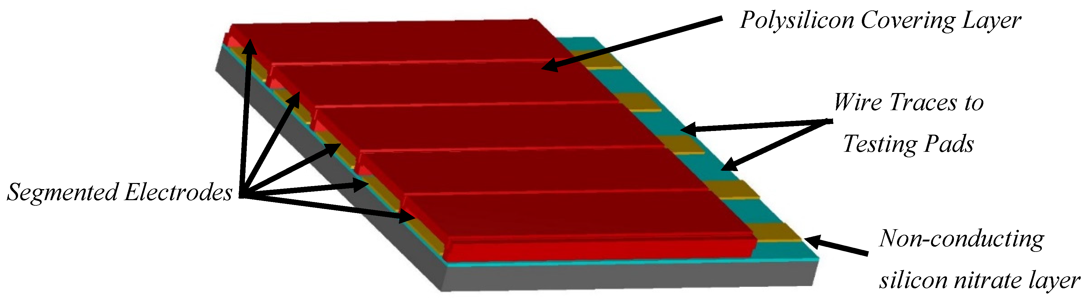
The design for the actuating ‘zipper arms’ consists of four modified beams fabricated from a 1.5 micron thick doped polycrystalline silicon layer and connected to the central platform. The beams are connected on one side to the silicon nitrate coated substrate and on the other side to the 500 × 500 micron platform. As shown in Figure 2, the design uses a platform to attach a post with an additional reflective surface to the top in order to provide the necessary specular surface for optical beam steering. Underneath the ‘zipper’ beams, will be individual channel for the electrode made of 0.5 micron thick polysilicon. The segmented channels are electrically isolated from the covering layer by an air gap providing a dielectric separation. (Figure 3) The individual electrodes are designed as wide as physically allowable in order to maximize the actuation pad area and reduce the required actuation voltage. The segmented channels are connected through doped polysilicon wire traces to pads for testing. The intended function of the design is that when a voltage is provided between a segmented actuation electrode and the zipper beam, it will result in the beam actuating. By varying the number of electrode channels with a potential applied, enhanced control of the deflection angle will be attained. Additionally, by measuring the capacitance between the unactuated segment of the zipper beam and the individual electrodes, modeling shows that we will be able to measure deflection angle and distance.
After fabrication, testing of the design consists of applying varying potentials to the segmented channels while keeping the zipper beam at ground voltage using a microelectronic probe test station. Measurement of the device displacement is accomplished using a Zygo® white light interferometer. Multiple variations on this design were modeled and will tested once received from fabrication foundry. The design varied parameters for the fabricated designs are number of zipper segments and the zipper design geometry. A two-sided zipper beam and a single sided were modeled and will be tested. Additionally, the device will be evaluated for its ability to be used as a sensor to detect the deflection of the zipper beam. Testing for capacitance will also be completed using the probe test station. After modeling, testing will be completed for capacitance is as follows: during actuation, one will be used as the sensor electrode. Instead of applying a potential to this channel for actuation, a capacitance value will be measured. As the beam is actuated using the other segmented electrodes, modeling shows that the capacitance between the beam and the electrode will change. This capacitance can be used for measurement of the displacement of the beam similar to designs that are currently used in other MEMS applications [2,3].
3. Results and Discussion
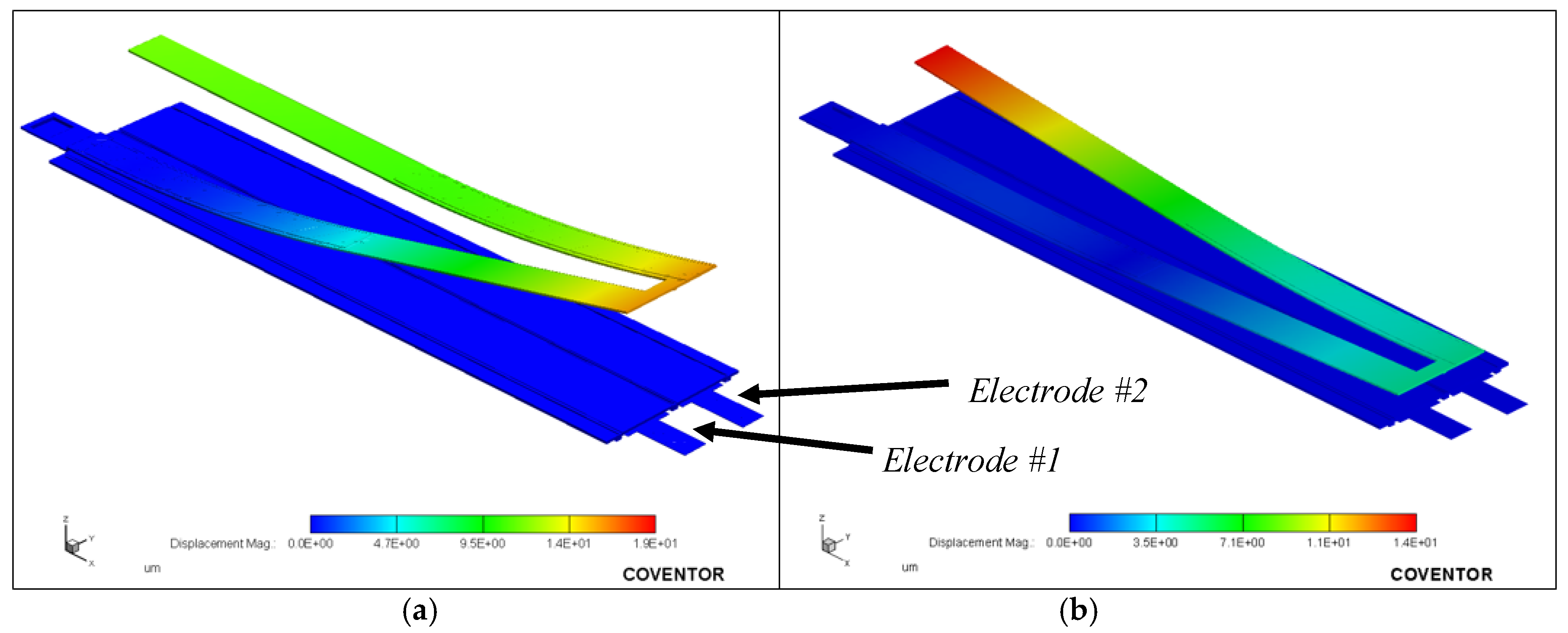
In order to determine if our approach was valid before fabrication and prototype testing, modeling was performed. Figure 4 shows finite element analysis (FEA) of a two beam zipper arm and platform along with calculated displacement from the bimorph beams when a single segment electrode is actuated. Complete actuation or “pull-in” of a single segment of a 500 micron beam occurred at 20 V. Table 1 provides modeled capacitance values from actuating individual electrode segments causing a corresponding deflection of the platform and change in capacitance value at the measured electrodes.
4. Conclusions
Modeling has showed proof of concept for our novel design of using segmented electrode channels for improved control and measurement of electrostatically actuated beams. The next step will be to validate these modeled results with device testing. Devices will be tested upon receipt and before conference presentation.
Acknowledgments
The authors would like to thank clean room technical staff including Rich Johnson for assistance. Funding for this research has been provided by the U.S. Air Force.
Conflicts of Interest
The authors declare no conflict of interest.
Disclaimer
The views expressed in this article are those of the authors and do not reflect the official policy or position of the United States Air Force, Department of Defense, or the U.S. Government.
References
- Walton, J.P.; Coutu, R.A., Jr.; Starman, L. Modeling and simulations of new electrostatically driven, bimorph actuator for high beam steering micromirror deflection angles. SPIDE Proc. 2015, 9375, 93750Y. [Google Scholar] [CrossRef]
- Reissman, T.; Garcia, E.; Lobontiu, N.; Nam, Y. Integrated Electrostatic Micro-Sensors for the Development of Modeling Techniques of Defects in the Actuation of Large Micro-electrmechanical Systems (MEMS). SPIDE Proc. 2006, 6152, 615238. [Google Scholar] [CrossRef]
- Nelatury, S.R.; Gray, R. Relation between charge on free electrodes and the response of electrostatic MEMS actuators and sensors. SPIDE Proc. 2012, 8373, 83732P. [Google Scholar] [CrossRef]
Figure 1.
SEM image of current iteration of the bimorph electrostatically actuating micromirror [1].
Figure 1.
SEM image of current iteration of the bimorph electrostatically actuating micromirror [1].

Figure 2.
Designs of electrostatically actuated mirror with segmented electrodes underneath the zipper beams for actuating a 500 micron × 500-micron platform. (a) is a two-segment and (b) is a five-segment zipper beam. Image was created using L-Edit® software under license to Air Force Institute of Technology.

Figure 3.
Three-dimensional cross-section model of five-segment electrode structure surrounded by cover to electrically isolate from actuating zipper beams. Image was created using L-Edit® software under license to Air Force Institute of Technology.
Figure 3.
Three-dimensional cross-section model of five-segment electrode structure surrounded by cover to electrically isolate from actuating zipper beams. Image was created using L-Edit® software under license to Air Force Institute of Technology.

Figure 4.
This figure shows the displacement results for a two-segment, 500 micron zipper beam when a voltage is applied to electrode #1; (a) shows the 0 V condition and (b) shows when 24 V is applied. Data was calculated using Coventorware® software under license to Air Force Institute of Technology.


Table 1.
This table shows beam vertical displacement and change in individual electrode capacitance based when a voltage is applied to electrode #1. Data was calculated using Coventorware® software under license to Air Force Institute of Technology.
Table 1.
This table shows beam vertical displacement and change in individual electrode capacitance based when a voltage is applied to electrode #1. Data was calculated using Coventorware® software under license to Air Force Institute of Technology.
| Electrode #1 Voltage (V) | Height of Beam Vertex (µm) | Change in Capacitance Electrode #2 (fF) |
|---|---|---|
| 0 | 18.54 | 0 |
| 6 | 18.32 | 0.12 |
| 12 | 17.38 | 0.69 |
| 18 | 11.78 | 5.44 |
| 24 | 4.72 | * |
* Capacitance was not calculated for 24 V case.
© 2017 by the authors. Licensee MDPI, Basel, Switzerland. This article is an open access article distributed under the terms and conditions of the Creative Commons Attribution (CC BY) license (https://creativecommons.org/licenses/by/4.0/).
Share and Cite
MDPI and ACS Style
Waggoner, K.; Lake, R.; Starman, L.; Walton, J. Segmented Control of Electrostatically Actuated Bimorph Beams. Proceedings 2017, 1, 306. https://doi.org/10.3390/proceedings1040306
AMA Style
Waggoner K, Lake R, Starman L, Walton J. Segmented Control of Electrostatically Actuated Bimorph Beams. Proceedings. 2017; 1(4):306. https://doi.org/10.3390/proceedings1040306
Chicago/Turabian StyleWaggoner, Kullen, Robert Lake, Lavern Starman, and John Walton. 2017. "Segmented Control of Electrostatically Actuated Bimorph Beams" Proceedings 1, no. 4: 306. https://doi.org/10.3390/proceedings1040306