Constructing a Transparent Air Chamber for an Innovative Ventilation System in an Operating Room †


1
LUXETEC, Department of Electric Engineering and Energy Technology, Vrije Universiteit Brussels, 1050 Ixelles, Belgium
2
Mechanics of Material and Constructions, Vrije Universiteit Brussels, 1050 Ixelles, Belgium
*
Author to whom correspondence should be addressed.
†
Presented at the 18th International Conference on Experimental Mechanics (ICEM18), Brussels, Belgium, 1–5 July 2018.
Proceedings 2018, 2(8), 376; https://doi.org/10.3390/ICEM18-05199
Published: 4 May 2018
(This article belongs to the Proceedings of The 18th International Conference on Experimental Mechanics)
Abstract
:While surgical techniques have been improving during last decades to the benefit of patients’ safety, infections are still recorded. It is in part due to airborne particles entering the wound during surgery, as a result of the disturbance of the unidirectional flow of clean air (LAF) by the presence of a surgical luminaire system. To prevent this negative interaction, an integrated system of light and ventilation has been designed. However, this system is still conceptual and a mechanical design is needed to prototype the system. Compliance with the European standard on surgical luminaires and the Heating, Ventilation and Air-Conditioning (HVAC) guidelines for operating rooms (OR) have to be checked for this prototype. We thus perform a structural analysis of the air chamber using Autodesk Inventor and SCIA Engineer considering different partitioning scenarios. The impact of each configuration is then assessed by considering the optical performance in the optical simulation TracePro. By comparing shifts in the results to a reference scenario an optimized configuration can be chosen. By consequence, a good balance between optical performance and mechanical strength is determined and leads to an optimized supporting solution. This mechanical design further enables us to build the integrated concept that aims to suppress the negative interaction between light and ventilation in the operating theater.
1. Introduction
The Belgian Superior Health Council reports in 2013 that 2% of surgical procedures lead to Surgical Site Infections (SSI) [1]. Postoperative infection rates of 1.6%, 2.6% and 5.6% are respectively reported in Germany, the USA, and low and middle-income countries [2]. This rate rises to 15% in Brazil [3]. One of the mechanisms that lead to SSI relies on microscopic organisms, such as bacteria, which are in suspension in the air. These airborne microorganisms are transported by particles like dust or aerosols. Usually, these are harmless due to the protection of the skin which acts as a natural defense barrier. However, during a surgery the skin is opened, allowing for particles to enter the wound. Depending on various factors, as the immune system of the patient, the point of entry, the bacterial load etc... the microorganisms may thrive and lead to an infection. Irrespective of (HEPA) filtering the air supply, bacteria, mainly originating from the operating staff and the patient itself, can become airborne and infect the patient.
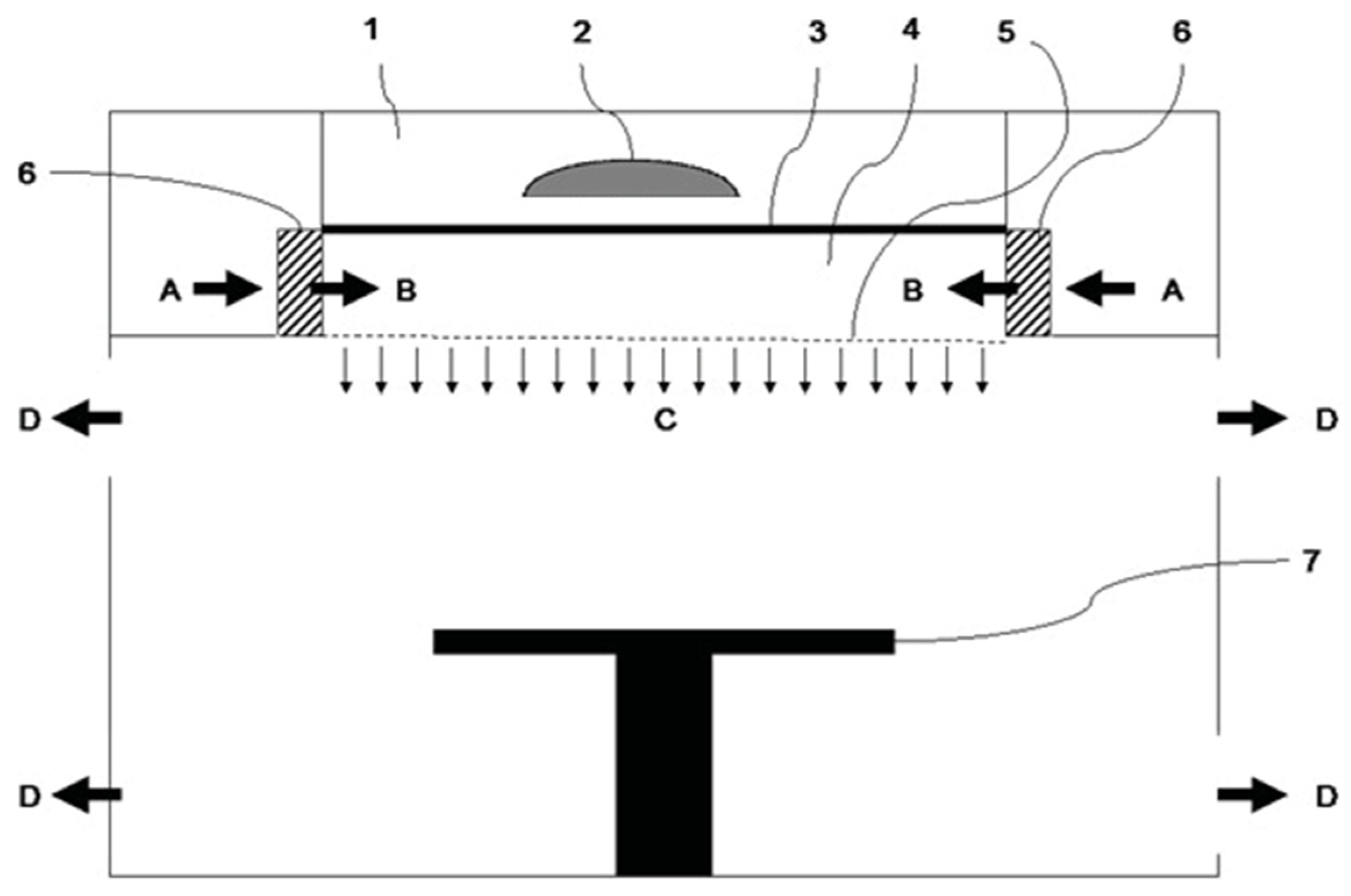
To control air quality and minimize contamination, technical standards and guidelines on the design of the HVAC system were written. Ultra-clean ventilation systems, commonly known as laminar air flow (LAF) are usually prescribed. LAF systems provide a unidirectional flow of air. They are commonly mounted in the ceiling (vertical flow). The air must flow from the cleanest source (LAF system) to the least clean area (outside the operating room) without mixing clean and non-clean air before reaching the wound. However, their efficiency is limited by the presence of a surgical luminaire system beneath the ventilation outlet which disturbs the pattern of the laminar flow [4]. It creates turbulence allowing for microorganisms from outside the ultra-clean zone to enter the wound zone. To prevent this negative interaction between the ventilation system and the surgical lighting, Jacobs et al. dealt with the optical design of an integrated light and ventilation system, which concept is subject to a patent [5]. The positions of the two main components are switched, the luminaires being above the outlet of the ventilation system. The air is provided from the sides (A) where it is filtered by HEPA filters, then enters (B) a chamber which lower surface is a perforated plate that produces a downwards laminar airflow (C). Figure 1 from [6] details this configuration.
However, this system is still conceptual and needs a mechanical design to be built: currently air chambers often consist of metal plates but switching the positions of luminaires and ventilation requires the chamber to be transparent and be able to comply with the European standard for surgical luminaires [6]. As the material of the air chamber needs to be changed, its ability to be perforated and produce a laminar airflow complying with the Heating, Ventilation and Air-Conditioning (HVAC) guidelines for operating rooms has to be checked too. Jacobs et al. already showed that the integrated system is able to comply with the European standard concerning surgical luminaires [7]. However, this work did not consider the construction aspects. The plates constituting the upper and lower surfaces of the chamber can only be supported on their sides, due to the presence of the luminaire system. Being loaded by their self-weight and a force induced by the airflow, they are subject to a bending moment and deflect. This physical phenomenon determines both their dimensions and the mounting method and impacts the optical efficiency of the system. We thus perform a design aiming at optimizing the supporting structure of this air chamber regarding its optical properties.
2. Structural Analysis of the Transparent Surfaces
To design the transparent plates of the chamber, several parameters, which are dependent on each other, need to be determined: the material, the partitioning, the thicknesses of the plates constituting the chamber, the supporting elements and the diameter and pitch of the perforations.
2.1. Material
The transparent plates constituting the air chamber are chosen in polycarbonate. This material has interesting properties for the medical sector [8]: It has glasslike optical properties and provides “an unusual combination of strength, rigidity, and toughness” which prevents dangerous failures. Its high heat resistance enables its placement close to a lighting system without unwanted deformations. In addition, it can be disinfected using usual methods, crucial asset for a use in OR. Finally, polycarbonate can be drilled without the formation of cracks, which is necessary to produce the laminar air flow [9].
2.2. Partitioning
An air chamber of 3 × 3 m is chosen, as it is the largest size used in practice, allowing an incident angle of light about 24° assuming dimensions given in part 3. A single plate of this dimension would not be optimal, leading to a thick (4 cm) and heavy element (430 kg). It is thus necessary to partition the plates in a certain number of elements to determine. This number is crucial to derive the remaining unknowns and have a strong impact on light as the supporting elements cannot be made of polycarbonate and are thus chosen in steel. Six scenarios of partitions are considered: 10 × 10, 8 × 8, 6 × 6, 5 × 5, 4 × 4 and 3 × 3 elements.
2.3. Polycarbonate Plates
The polycarbonate plates, being loaded by their self-weight, are subject to a bending moment, leading to a deflection. The maximum deflection is determined by the usual deflection limits used in the construction sector. They minimize the possibility of damage and provide a feeling of safety for the room occupants by limiting the maximum displacement of elements to their span divided by 240 for non-brittle material.
To determine the minimum thickness allowing to comply with the deflection rule, polycarbonate plates corresponding to the different scenarios are modeled in Autodesk Inventor, and a deflection analysis is performed. The plates being likely to be supported on a small surface on each edge, a rotation at the supports is forecasted, modeled by pinned connections. The self-weight is defined, as well as a wind force for in-draft air transfers, taken as 300 Pa, value commonly used in the construction sector. The load induced by the airflow of the ventilation system is not considered, as the maximum air velocity of ν = 0.35 m/s [10] prescribed by standards leads to a pressure of 0.0735 Pa, which is negligible compared to the aforementioned forces. The lower and upper surfaces of the chamber being respectively constituted of perforated and non-perforated plates, the analysis is performed for both. Circular perforations with a 5 mm diameter and a pitch of 15 × 15 mm is used, as [11] showed that a laminar airflow is achievable for these values. The results of the Autodesk Inventor analysis on polycarbonate plates are summarized in Table 1.
2.4. Inner Supporting Beams
T-profiles steel beams are chosen as supporting structure to mount the polycarbonate plates, based on the suspended ceiling model. To determine the cross-sections dimensions, a steel frame made of 1D elements is modeled for each scenario in SCIA Engineer. Connections between steel beams prevent rotation and supports are defined as pinned and rolled. The self-weight of the beams is defined, and the surface-loading of the polycarbonate plates’ weight and the wind force are applied. The most efficient profiles among European standard equal flange steel tee sections [12] are chosen by checking the compliance with Eurocode 3: Design of steel structures [13] and a maximum deflection of 3mm under Serviceability Limit Stress combination. Table 2 summarizes the final chosen profiles and the design forces and resistances. For ease of construction, the same supporting structure is considered for the lower and upper side of the chamber. The loads of the non-perforated plates are taken into account as they induce more load than the perforated ones, except when the plate thickness is higher.
3. Optical Assessment
To assess the impact of each scenario configuration on the optical properties, the inner supporting structure, modeled in Autodesk Inventor, is imported into TracePro. The following elements are imported:
- a measurement plane of 60 × 60 cm located at ground level to plot the illuminance on a 128 × 128 pixels grid
- The mounting structure of the chamber, defined with a reflectance of 0.4 and an absorbance of 0.60 corresponding to stainless steel [14]. Its lower and upper sides are respectively located at 1.50 m and 2.20 m.
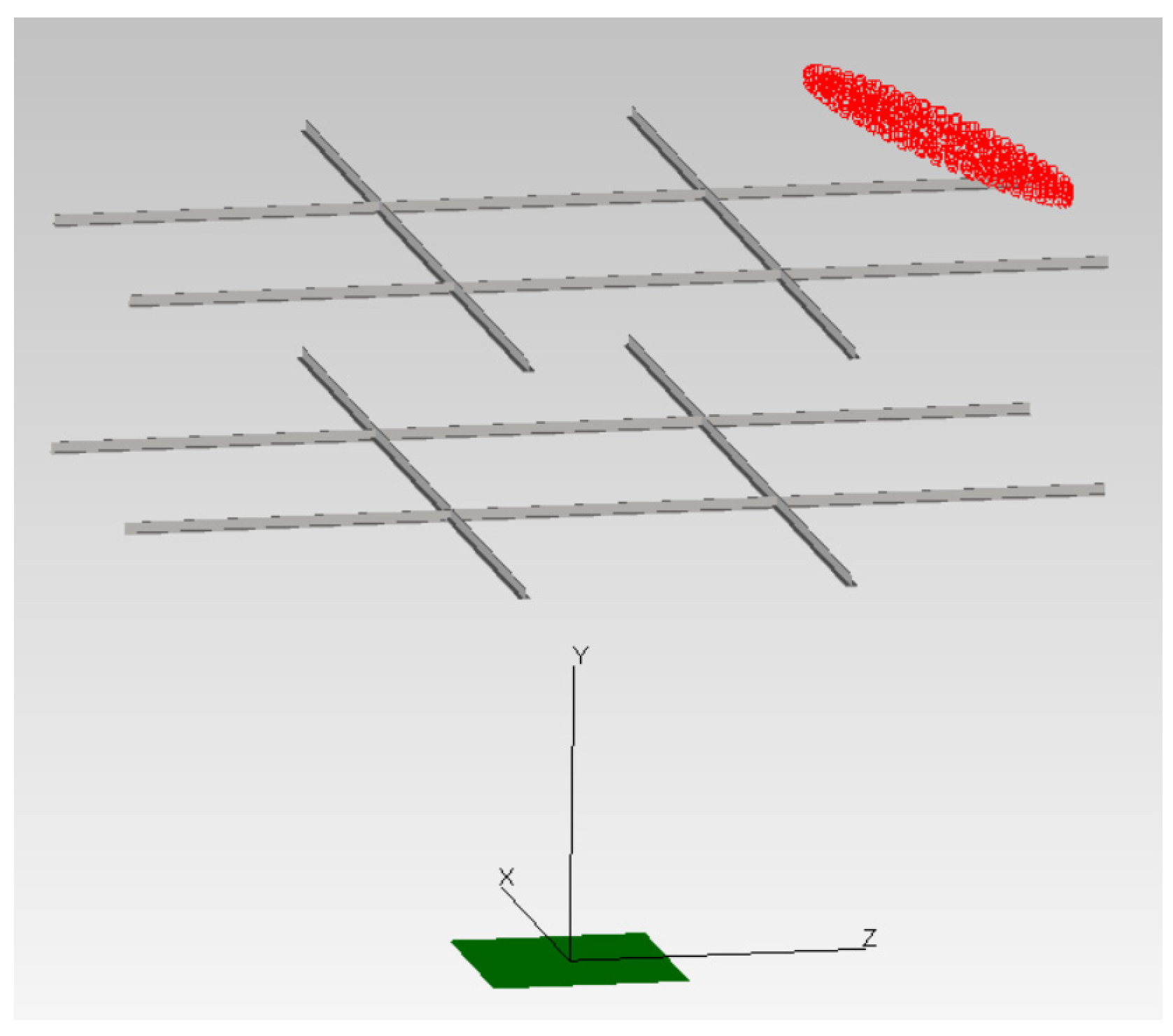
- A lighting system representing the configuration proposed by [7] for the surgical luminaire: 214 LEDs arranged in concentric regular polygons in a single plane around a center. The diameter of the system is 85 cm. Each LED has a luminous flux of 60 lumen equipped with focusing optics, resulting in an intensity distribution with a FWHM of 7° for each LED. Rays of monochromatic light with a wavelength λ = 546.1 nm are used. It is located at a distance of 2.70 m from the center point of the measurement plane. The incident angle varies among 0°, 12° and 24° for a center of the lighting system along the z axis and the diagonal of the chamber (Figure 2), totaling 5 studied positions.
For a given scenario and position of the luminaire system, the error percentage on the illuminance compared to a reference situation, where no supporting structure is present, is calculated for each pixel according the following formula:
where E is the illuminance for the considered configuration and Eref the illuminance for the reference situation. The average error is computed on the measurement plane and then on the 5 studied positions. To detect the introduction of potential patterns, which lead to non-uniform errors, the first derivative along the vertical and horizontal axis are computed, and its maximum is retrieved for each studied position. Its average is computed on all these configurations. A prior median filter on 8 by 8 pixels neighborhoods removes small-size spots while keeping the illuminance variations of patterns. Results can be read in Table 3.
e = (E − Eref)/Eref,
The effect of the supporting frame is lower in the 3 × 3 scenario compared to other scenarios: The introduction of a pattern is hardly noticeable on the illuminance plots, confirmed by the lowest error differences. The mean illuminance error is also the lowest, meaning that the quasi-uniform decrease of illuminance can be compensated with minimum efforts.
4. Conclusions
A mechanical design for an integrated system for lighting and ventilation in the surgery room has been developed. A segmentation of the transparent chamber in 3 × 3 has been chosen as this combines low impact on the illuminance, ease of construction and lightness of the structure. The remaining structural elements do not affect the optical performance and can then be designed. L-profile steel beams are chosen for the edges of the upper and lower surfaces. Steel plates close the chamber on the four sides and transfer the load of the chamber to the supports. Two of those plates have connections for the ventilation system. Hangers are planned to take the total load of the chamber depending on the ceiling of the operating room and the luminaire system. Finally, the welded connections between steel elements can be designed. This mechanical design, optimized for its structural and optical properties, allows to build the integrated concept aiming at the suppression of negative interactions between light and ventilation in operating theaters. An assessment of this innovative system will validate this solution to reduce post-operative infections.
Author Contributions
V.D. develops his master thesis under the supervision of the promoters V.A.J. and D.V.H. V.A.J. and V.D. designed the simulations. V.D. performed them. V.A.J. and V.D. wrote the paper.
Funding
No funding was received in support of the research work nor for covering costs to publish in open access.
Conflicts of Interest
The authors declare no conflict of interest.
References
- Ramachandran, S.; Research Associate Healthcare (EMEA). Surgical Site Infections in Europe—Paying too High a Price. Available online: http://www.frost.com/prod/servlet/market-insight-print.pag?docid=85996734 (accessed on 29 April 2018).
- Tartari, E.; Weterings, V.; Gastmeier, P.; Baño, J.R.; Widmer, A.; Kluytmans, J.; Voss, A. Patient engagement with surgical site infection prevention: An expert panel perspective. Antimicrob. Resist. Infect. Control 2017, 6, 45. [Google Scholar] [CrossRef] [PubMed]
- Nastase, I.; Croitoru, C.; Vartires, A.; Tataranu, L. Indoor Environmental Quality in Operating Rooms: An European Standards Review with Regard to Romanian Guidelines. Energy Procedia 2016, 85, 375–382. [Google Scholar] [CrossRef]
- Aganovic, A.; Cao, G.; Stenstad, L.-I.; Skogås, J.G. Impact of surgical lights on the velocity distribution and airborne contamination level in an operating room with laminar airflow system. Build. Environ. 2017. [Google Scholar] [CrossRef]
- Improved System and Method for Ventilation and Illumination of an Operating Room. Available online: https://patents.google.com/patent/EP3075368A1/sv (accessed on 29 April 2018).
- International Electrotechnical Commission. IEC 60601-2-41: Medical Electrical Equipment Part 2-41: Particular Requirements for Basic Safety and Essential Performance of Surgical Luminaires and Luminaires for Diagnosis; International Electrotechnical Commission: Geneva, Switzerland, 2009. [Google Scholar]
- Jacobs, V.A. Design Considerations for LED Based Surgical Luminaries. Ph.D. Thesis, Vrije Universiteit Brussel, Belgium, Brussels, 2015. [Google Scholar]
- Powel, D. Medical Applications of Polycarbonate. Available online: https://www.mddionline.com/medical-applications-polycarbonate (accessed on 29 April 2018).
- Nau, A.; Scholtes, B.; Rohleder, M.; Nobre, J. Application of the hole drilling method for residual stress analyses in components made of polycarbonate. J. Plast. Technol. 2011, 7, 66–85. [Google Scholar]
- Vereniging Contamination Control Nederland. Nieuwe Richtlijn: Nieuwe ziekenhuisrichtlijn in Zwitserland en Duitsland. VCCN Mag. 2004, 17, 3. [Google Scholar]
- Van Gaever, R. Design Considerations of the Operating Room Ventilation System: A Numerical and Experimental Study. Ph.D. Thesis, Vrije Universiteit Brussel, Belgium, Brussels, 2015. [Google Scholar]
- Equal Flange Tees, Tee Sections Specification, Dimensions, Properties. T Profile Accordance to standard EN 10055:1995. Available online: http://www.b2bmetal.eu/en/pages/index/index/id/64/ (accessed on 29 April 2018).
- European Committee for Standardisation. EN 1993-1-1: Eurocode 3: Design of Steel Structures—Part 1-1: General Rules and Rules for Buildings; European Committee for Standardisation: Brussels, Belgium, 2005. [Google Scholar]
- Lighting Materials for Simulation. Available online: http://lighting-materials.com/ (accessed on 29 April 2018).
Figure 1.
Innovative concept of an OR that integrates light and ventilation: 1. Light chamber with transparent floor; 2. Primary mobile luminaire; 3. Pressure rooms; 4. Transparent ceiling; 5. Perforated transparent air outlet; 6. HEPA filters; 7. Operating table; A. Conditioned air supply; B. Filtered ultra-clean air; C. Downward flow; D. Air outlet.

Figure 2.
TracePro model constituted of the measurement plane (green), the supporting frame (grey) and the lighting system (red) for the 3 × 3 scenario with an incident angle of 24°.
Figure 2.
TracePro model constituted of the measurement plane (green), the supporting frame (grey) and the lighting system (red) for the 3 × 3 scenario with an incident angle of 24°.


Table 1.
Deflection limit δmax, deflections δ and thicknesses t of perforated and non-perforated polycarbonate plates for the considered partitioning scenarios. The perforated plate analysis failed to compute for the 4 × 4 and 3 × 3 scenarios due to the high number of perforations. Deflections were deducted from the average increase factor between non-perforated and perforated plates of the other scenarios.
| δmax [mm] | Non-Perforated Plates | Perforated Plates | |||
|---|---|---|---|---|---|
| t [mm] | δ [mm] | t [mm] | δ [mm] | ||
| 10 × 10 | 1.25 | 4 | 0.8 | 4 | 0.93 |
| 8 × 8 | 1.56 | 5 | 1.04 | 5 | 1.21 |
| 6 × 6 | 2.08 | 6 | 1.97 | 7 | 1.49 |
| 5 × 5 | 2.50 | 8 | 1.83 | 8 | 2.15 |
| 4 × 4 | 3.12 | 10 | 2.43 | 10 | 2.21 ± 0.017 |
| 3 × 3 | 4.17 | 13 | 3.79 | 14 | 3.62 ± 0.021 |
Table 2.
Chosen profile for supporting beams, design moment MEd and shear force VEd under the Ultimate Limit Stress combination, design cross-sectional moment Mc,Rd and shear force Vpl,Rd, maximum deflection δmax and actual deflection δ under the Serviceability Limit Stress combination.
Table 2.
Chosen profile for supporting beams, design moment MEd and shear force VEd under the Ultimate Limit Stress combination, design cross-sectional moment Mc,Rd and shear force Vpl,Rd, maximum deflection δmax and actual deflection δ under the Serviceability Limit Stress combination.
| Scenario | Profile | MEd [Nm] | Mc,Rd [Nm] | VEd [N] | Vpl,Rd [N] | δ [mm] | δmax [mm] |
|---|---|---|---|---|---|---|---|
| 10 × 10 | T60 | 215 | 1.28 × 10³ | 316 | 50.3 × 10³ | 2.9 | 3 |
| 8 × 8 | T70 | 281 | 2.07 × 10³ | 407 | 67.3 × 10³ | 2.0 | 3 |
| 6 × 6 | T70 | 333 | 2.07 × 10³ | 473 | 67.3 × 10³ | 2.4 | 3 |
| 5 × 5 | T70 | 358 | 2.07 × 10³ | 503 | 67.3 × 10³ | 2.6 | 3 |
| 4 × 4 | T80 | 480 | 82.5 × 10³ | 657 | 82.5 × 10³ | 2.1 | 3 |
| 3 × 3 | T80 | 548 | 82.5 × 10³ | 720 | 82.5 × 10³ | 2.3 | 3 |
Table 3.
Average of maximum errors emax and of error uniformities u on the 5 studied positions.
| 3 × 3 | 4 × 4 | 5 × 5 | 6 × 6 | 8 × 8 | 10 × 10 | |
|---|---|---|---|---|---|---|
| emax | 22% | 37% | 32% | 26% | 43% | 34% |
| u | 0.60 | 0.50 | 0.56 | 0.47 | 0.55 | 0.48 |
Publisher’s Note: MDPI stays neutral with regard to jurisdictional claims in published maps and institutional affiliations. |
© 2018 by the authors. Licensee MDPI, Basel, Switzerland. This article is an open access article distributed under the terms and conditions of the Creative Commons Attribution (CC BY) license (https://creativecommons.org/licenses/by/4.0/).
Share and Cite
MDPI and ACS Style
Desmars, V.; Hemelrijck, D.V.; Jacobs, V.A. Constructing a Transparent Air Chamber for an Innovative Ventilation System in an Operating Room. Proceedings 2018, 2, 376. https://doi.org/10.3390/ICEM18-05199
AMA Style
Desmars V, Hemelrijck DV, Jacobs VA. Constructing a Transparent Air Chamber for an Innovative Ventilation System in an Operating Room. Proceedings. 2018; 2(8):376. https://doi.org/10.3390/ICEM18-05199
Chicago/Turabian StyleDesmars, Victorien, Danny Van Hemelrijck, and Valéry Ann Jacobs. 2018. "Constructing a Transparent Air Chamber for an Innovative Ventilation System in an Operating Room" Proceedings 2, no. 8: 376. https://doi.org/10.3390/ICEM18-05199