Investigations of Cruciform Specimen Designs for Biaxial Tensile Testing of SMC †

1
Institute of Engineering Mechanics, Chair for Continuum Mechanics, Karlsruhe Institute of Technology (KIT), 76133 Karlsruhe, Germany
2
Institute of Mechanics, Chair for Continuum Mechanics, Karlsruhe Institute of Technology (KIT), 76133 Karlsruhe, Germany
*
Author to whom correspondence should be addressed.
†
Presented at the 18th International Conference on Experimental Mechanics, Brussels, Belgium, 1–5 July 2018.
Proceedings 2018, 2(8), 411; https://doi.org/10.3390/ICEM18-05279
Published: 31 May 2018
(This article belongs to the Proceedings of The 18th International Conference on Experimental Mechanics)
Abstract
:This proceedings paper presents the investigation of different cruciform specimen designs for the characterization of Sheet Molding Compounds under biaxial loading. Biaxial tensile tests allow the investigation of damage evolution under multiaxial stress states, which is particularly interesting due to the different damage phenomena in composite materials. A key challenge is to find a suitable specimen shape, because typical cruciform specimens fail in the arms before damage occurs in the area of interest which is the area of the biaxial stress state in the center region of the specimen. For all of the introduced designs the stiffness degradation is analyzed more in detail and compared to that of a uniaxial bone specimen. For the best performing specimen which is reinforced by unidirectional reinforced tapes on the arms, the strain field is analyzed by finite element simulations, taking into account the mechanical properties of the different layers of the specimen. Especially in the center area and at critical points, strain concentrations and non-symmetrical strain distributions are analyzed and evaluated.
1. Introduction
Sheet molding compounds (SMC) as discontinuous fiber reinforced composites combine high strength and stiffness and a low density with an economical production and is, thus, an ideal lightweight material. The detailed understanding of the mechanical behavior of SMC presents, however, a challenge to composite material science and mechanics. The focus of the present work lies on biaxial tensile testing of SMC. Biaxial stress and strain states cover a wide range of application loads. Furthermore damage modeling increases in interest. The detailed characterization of damage, also under multiaxial stress states, is indispensable for the understanding of the damage phenomena and serves to validate damage models. The cruciform specimen design is the basic prerequisite for corresponding experiments.
In the past many attempts have been made to find an appropriate specimen design. Several authors proposed specimen designs varying the cut type, the slits type and the reduced center area type [1]. The first standardization is [2] but applies only for sheet metals. For example [3,4,5,6] conducted research to find specimen shapes for fiber reinforced polymers. Serna Moreno et al. ([7]) compared specimens for chopped glass-reinforced polyester and presented a specimen that was suitable to achieve failure in the center area in different loading cases but pointed out that there are still problems such as stress concentrations outside the center area.
The present work conducts further investigations on the proposed specimen designs documented in [8]. In Section 2 the material and the experimental methods are provided. Section 3 presents the preliminary work and the results of [8]. Section 4 shows the results of the investigation of the stiffness degradation for the different specimen designs. Section 5 discusses the results of finite element simulations of the best performing specimen to analyze the strain field in more detail.
2. Material and Experimental Methods
The investigated material is sheet molding compound (SMC) with an unsaturated polyester polyurethane hybrid (UPPH) as the matrix with 23 vol% glass fibers. Details to the manufacturing process can be seen in [9].
The biaxial testing device by Zwick which is used for the experiments in [8] and on which the investigations of this contribution are based consists of four horizontally positioned electro mechanical actuators that are arranged perpendicular to each other. Each axis has a load cell and allows for a maximum load of 150 kN. The strain is determined from the displacement of the axis and by an integrated optical system which measures the displacement of fife points glued on the bottom of the specimen. This system allows for a midpoint control which avoids undesirable bending loads. Additionally, a digital image correlation system by GOM, called ARAMIS 3D 4M, measures the strain field on the specimen. More details on the testing device, an exemplary cruciform specimen with the area of interest, and the definitions for the loading ratio and the averaged strain over the area of interest may be found in [8].
We have chosen two experimental procedures. In both experimental procedures, the load is applied in a cyclic way with long waiting times between the cycles to have the possibility to distinguish between the mechanical phenomena of elasticity, plasticity, viscoelasticity and damage. The first procedure is uniaxial tension and the second procedure is biaxial tension. The loading scenarios are described in detail in [8].
3. Specimen Designs
In [8] we defined criteria for the optimality of a cruciform specimen taken from [10]. We extended and adapted the criteria to the properties of SMC. These criteria are (1) Wide range of achievable strain states, (2) Damage dominantly in the area of interest, (3) Homogeneity of the strain field in the area of interest, (4) Robust parameter identification, (5) Large area of interest, (6) Low production effort. We investigated four specimen designs and compared them with regard to the afore mentioned optimality criteria and their weighting, whereas the observability of damage in the area of interest (criterion 2) is the most important criterion. The first design is an unreinforced specimen in line to the ISO norm [2]. To increase the stiffness of the specimen’s arms, we bonded strips on the specimen arms for the second design. For the other two designs, the specimens are taken from SMC plates which are reinforced by unidirectional reinforced tapes on both sides. These tapes are made of the same matrix material as the SMC material with endless carbon fibers. On each side of the SMC are two layers of the unidirectional reinforced material with a fiber orientation perpendicular to each other. Details about this manufacturing process can be found in [11]. The center area of the specimen is milled out by a gentle milling process. A cross section can be found in [8]. The shape of the milled out area was chosen manually from a large number (thousands) of FEM simulations. The different specimens are shown in Table 1.
The best performing specimen is the continuous reinforced geometry 1 (“Cont. Geom. 1” in Table 1). As a measure for the likelihood to observe damage in the area of interest serves the maximum strain reached in the entire load history until failure. For uniaxial tension, the geometry 1 reaches 0.87% of the failure strain of a uniaxial bone specimen, whereas the unreinforced reaches 0.53% (see table in [8]). In addition, with regard to some of the other criteria such as the size (criterion 5) and the homogeneity (criterion 3) of the area of interest, this specimen also performs best.
4. Stiffness Degradation
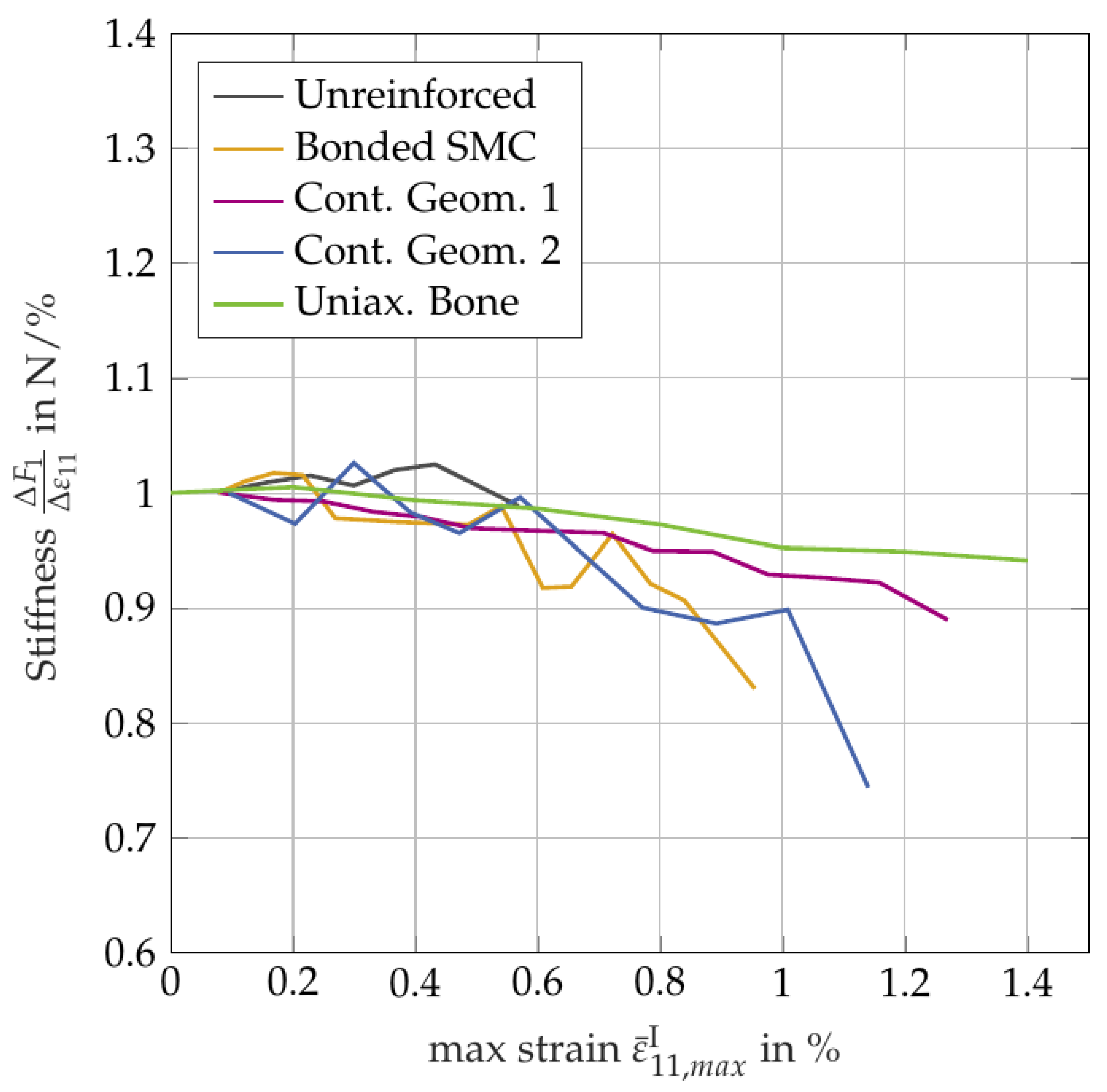
Since the most important criterion is the observability of damage in the area of interest, we analyzed the performance of the specimens with regard to this criterion in more detail. In the force strain diagrams of [8], a stiffness degradation after each loading cycle is already visible. This stiffness degradation, as one phenomenon of damage, is considered and compared for the different specimen designs for the uniaxial loading scenario. As the calculation of the stress is not straightforward, the force difference over the strain difference serves as a measure for the stiffness in -direction.
The values are taken at the beginning of each cycle after long waiting times to make sure that there are the same conditions regarding viscoelastic effects. The Δε for the stiffness calculation is about 1.1%. For the comparability, the values of the stiffness are normalized to the initial value of each specimen. Figure 1 depicts the stiffness over the maximum reached strain for all specimen designs and for a uniaxial bone specimen for comparison. The maximum reached strain is the maximum strain in the cycle before the measurement cycle which is the maximum strain ever reached in the loading history until the instant of measurement.
The stiffness degradation is clearly visible for all of the specimen designs except for the unreinforced specimen. The shape of the curves of the bonded specimen and of the geometry 2 shows a declining trend but with fluctuations. The geometry 1 of the unidirectional reinforced specimen shows the smoothest shape and, especially, the curve is the most similar to that of the uniaxial bone specimen which can be regarded as a reference. Summarizing, the geometry 1 of the unidirectional reinforced specimens performs best also with regard to the stiffness degradation investigation. However, the interpretation of the results requires caution because only a low number of experiments was performed (see [8]).
5. Investigation of the Strain Distribution
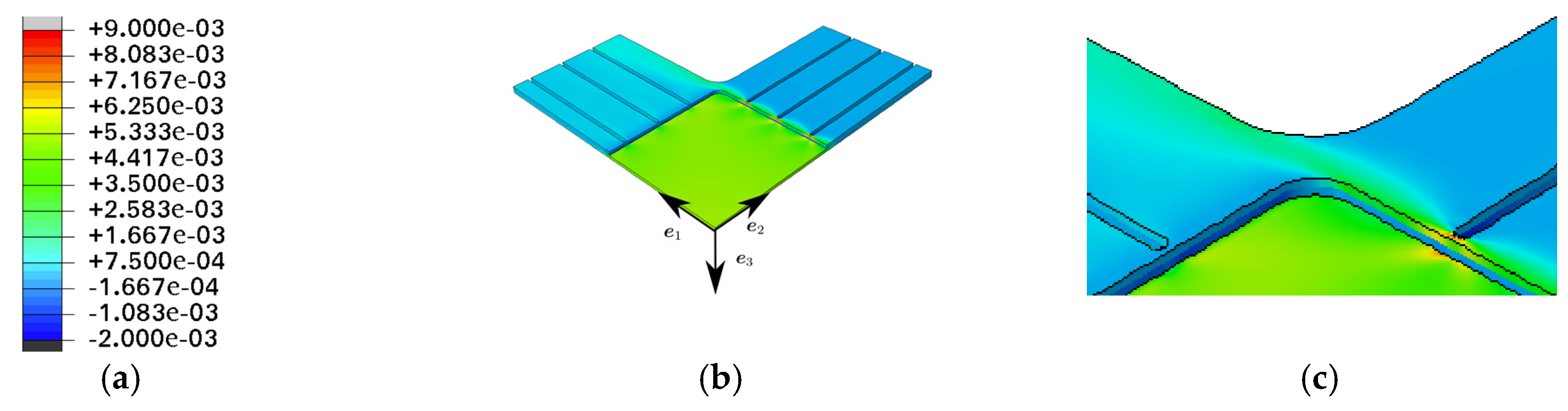
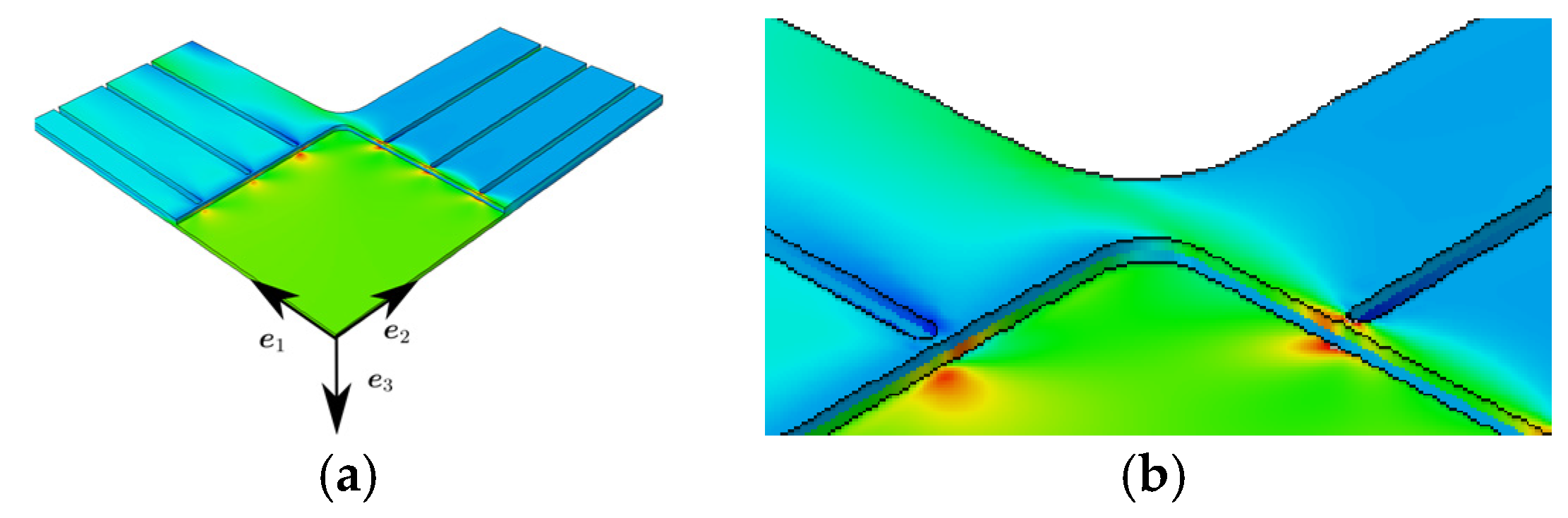
In [8] for the geometry 1 is shown, that failure occurs in the center area but possibly initiates close to the end of the slits. To investigate the strain distribution at the critical points and in the center area, and, to analyze the influence of the slits, the different layers, and the orientation of the reinforcing tapes, we performed finite element simulations. Whereas the finite element model in [8] is only a simplified model, we are now taking into account the different layers with their mechanical properties. Transversely isotropic material behavior is assumed for the SMC and for the reinforcing tapes. The mechanical constants are calculated by a Mori-Tanaka homogenization. A table of the parameters is provided in Appendix A. Figure 2a depicts the legend for the following contour plots. Figure 2, Figure 3 and Figure 4 show the results of the finite element simulations for the uniaxial loading and Figure 5, Figure 6 and Figure 7 for the biaxial loading. The inner layer of the reinforcing tapes which is directly connected to the SMC is reinforced in the -direction.
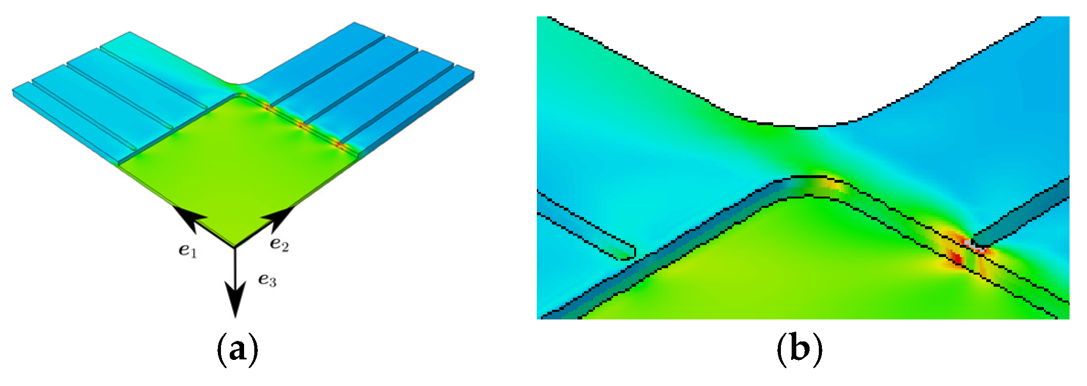
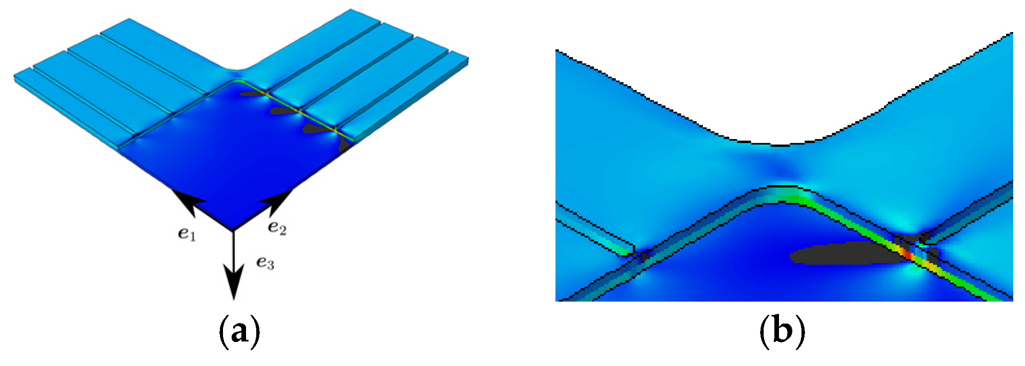
For the uniaxial load, strain concentrations are visible near to the slit’s end which are transferred by the inner layer, although the inner layer is reinforced in the -direction. The strain distribution shows only small fluctuations in the area of interest in a certain distance from the slit’s end. The normal strain is almost equal to the largest principal strain and the normal strain is almost equal to zero.
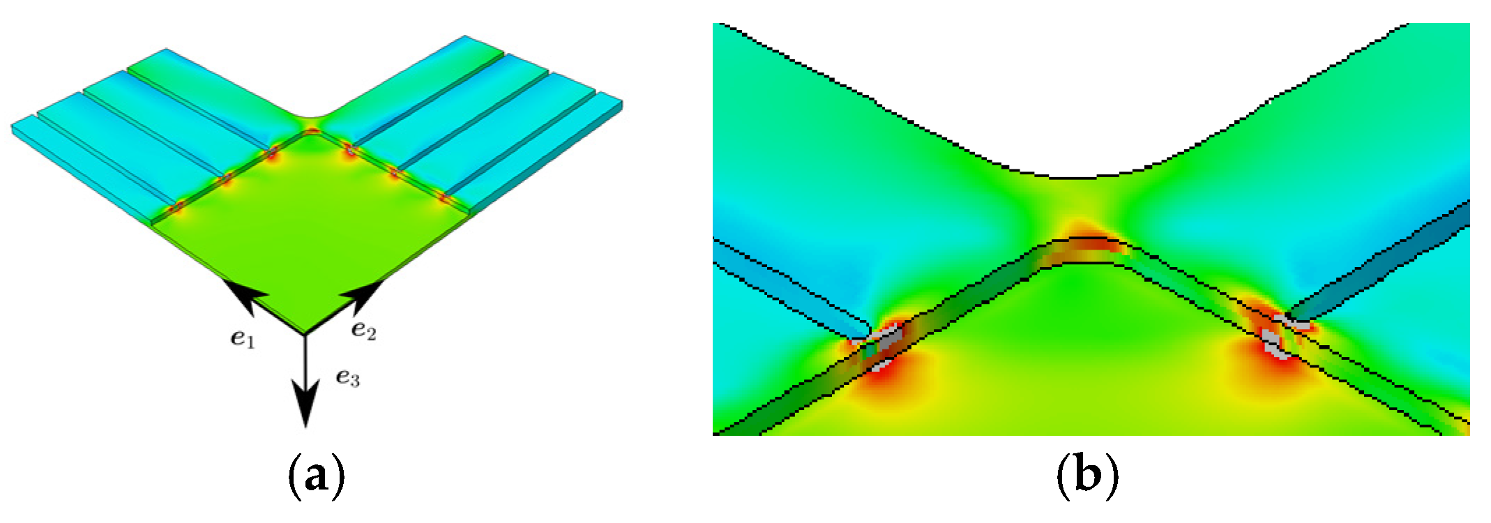
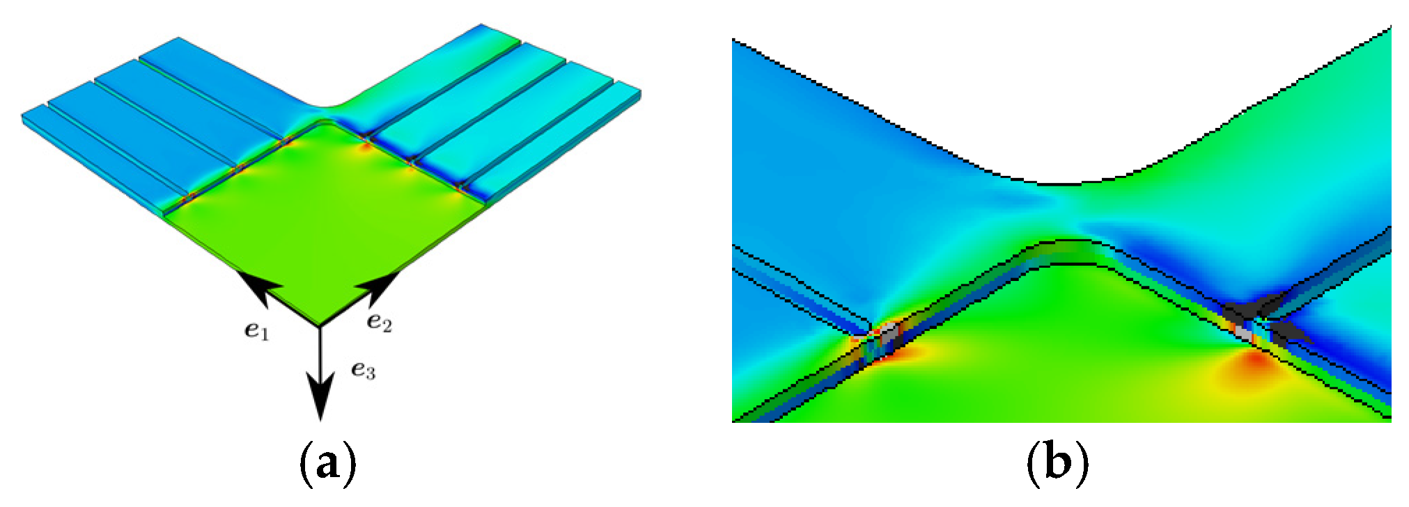
For the biaxial load, strain concentrations are visible at the slits’ end (see Figure 5a, Figure 6a and Figure 7a). The orientation of the unidirectional reinforcement causes non-symmetric strain distributions especially in the corners (see principal strain in Figure 6b), even though the geometry and the load is symmetric. The normal strain on the right side of the inner reinforcing tape at the slit’s end (mainly caused by the tension in -direction) is larger than the normal strain on the left side of the inner layer (mainly caused by the tension in -direction). This difference in strain is due to the reinforcement in -direction. This strain is transferred to the SMC material and causes a non-symmetric strain distribution. In a certain distance from the transition zone no influence is visible anymore.
In summary, it can be stated that there are strain concentrations at the slits’ end and a non-symmetric strain distribution due to the orientation of the reinforcing tapes. But with a certain small distance from the transition zone and the slits’ end the strain field is homogenous and approximate uniaxial or equi-biaxial. This is positive with regard to the optimality criterion 1. To optimize the performance of the specimen with regard to criterion 2, the shape of the slits or the orientation of the tapes should be varied.
Author Contributions
J.L., M.S., T.S. and T.B. discussed the different specimen designs and the reinforcement strategy and the results. J.L. performed the experiments and the post processing. M.S. was responsible for the finite element simulation. M.S. and J.L. perfomed the post processing of the finite element simulations. J.L. wrote the paper. All authors provided signigicant editing efforts towards the improvement of the paper.
Acknowledgments
We appreciate the support by David Bücheler (Fraunhofer Institute of Chemical Technology) for the UPPH SMC production, including the SMC with the unidirectional reinforcements. We appreciate thesupport by Anton Helfrich for manufacturing of the specimens regarding the milling process. The research documented in this paper has been funded by the German Research Foundation (DFG) within the International Research Training Group “Integrated engineering of continuous-discontinuous long fiber reinforced polymer structures” (GRK 2078). The support by the German Research Foundation (DFG) is gratefully acknowledged.
Conflicts of Interest
The authors declare no conflict of interest.
Appendix A

Table A1.
Parameter of the Mori-Tanaka homogenization. E: Young’s modulus, μ: Poisson’s ratio, : aspect ratio, : fiber volume fraction.
Table A1.
Parameter of the Mori-Tanaka homogenization. E: Young’s modulus, μ: Poisson’s ratio, : aspect ratio, : fiber volume fraction.
| E in GPa | μ | |||
|---|---|---|---|---|
| Carbon | 276 | 0.220 | 1000000 | 0.600 |
| Glass | 73 | 0.220 | 667 | 0.225 |
| Matrix | 3.06 | 0.299 |
References
- Ohtake, Y.; Rokugawa, S.; Masumoto, H. Geometry Determination of Cruciform-Type Specimen and Biaxial Tensile Test of C/C Composites. Key Eng. Mater. 1999, 164–165, 151–154. [Google Scholar] [CrossRef]
- International Organization for Standardization. Metallic Materials—Sheet and Strip—Biaxial Tensile Testing Method Using a Cruciform Test Piece; ISO 16842; International Organization for Standardization: Geneva, Switzerland, 2014. [Google Scholar]
- Makris, A.; Vandenbergh, T.; Ramault, C.; van Hemelrijck, D.; Lamkanfi, E.; van Paepegem, W. Shape optimisation of a biaxially loaded cruciform specimen. Polym. Test. 2010, 29, 216–223. [Google Scholar] [CrossRef]
- Makinde, A.; Thibodeau, L.; Neale, K.W. Development of an apparatus for biaxial testing using cruciform specimens. Exp. Mech. 1992, 32, 138–144. [Google Scholar] [CrossRef]
- Lamkanfi, E.; van Paepegem, W.; Degrieck, J.; Ramault, C.; Makris, A.; van Hemelrijck, D. Strain distribution in cruciform specimens subjected to biaxial loading conditions. Part 2: Influence of geometrical discontinuities. Polym. Test. 2010, 29, 132–138. [Google Scholar] [CrossRef]
- Gower, M.R.L.; Shaw, R.M. Towards a Planar Cruciform Specimen for Biaxial Characterisation of Polymer Matrix Composites (R). Appl. Mech. Mater. 2010, 24–25, 115–120. [Google Scholar] [CrossRef]
- Schemmann, M.; Lang, J.; Helfrich, A.; Seelig, T.; Böhlke, T. Cruciform Specimen Design for Biaxial Tensile Testing of SMC. J. Compos. Sci. 2018, 2, 12. [Google Scholar] [CrossRef]
- Moreno, M.C.S.; Vicente, J.L.M.; Cela, J.J.L. Failure strain and stress fields of a chopped glass-reinforced polyester under biaxial loading. Compos. Struct. 2013, 103, 27–33. [Google Scholar] [CrossRef]
- Hohberg, M.; Kärger, L.; Bücheler, D.; Henning, F. Rheological In-Mold Measurements and Characterizations of Sheet-Molding-Compound (SMC) Formulations with Different Constitution Properties by Using a Compressible Shell Model. Int. Polym. Process. 2017, 32, 659–668. [Google Scholar] [CrossRef]
- Smits, A.; van Hemelrijck, D.; Philippidis, T.P.; Cardon, A. Design of a cruciform specimen for biaxial testing of fibre reinforced composite laminates. Compos. Sci. Technol. 2006, 66, 964–975. [Google Scholar] [CrossRef]
- Bücheler, D. Locally Continuous-Fiber Reinforced Sheet Molding Compound; Karlsruhe Institute of Technology: Karlsruhe, Germany, 2017. [Google Scholar]
Figure 1.
Stiffness over the maximum strain reached in the area of interest over the whole loading history until the instant of the measurement.
Figure 1.
Stiffness over the maximum strain reached in the area of interest over the whole loading history until the instant of the measurement.

Figure 2.
(a) Legend for strain ε in all following contour plots (without unit) (b) FE (finite element) results for uniaxial load in -direction at a displacement of the specimen arms of 0.2 mm, normal strain (c) Detail from (b).
Figure 2.
(a) Legend for strain ε in all following contour plots (without unit) (b) FE (finite element) results for uniaxial load in -direction at a displacement of the specimen arms of 0.2 mm, normal strain (c) Detail from (b).

Figure 3.
(a) FE results for uniaxial load in -direction at a displacement of the specimen arms of 0.2 mm, largest principal strain (b) Detail from (a).
Figure 3.
(a) FE results for uniaxial load in -direction at a displacement of the specimen arms of 0.2 mm, largest principal strain (b) Detail from (a).

Figure 4.
(a) FE results for uniaxial load in -direction at a displacement of the specimen arms of 0.2 mm, normal strain (b) Detail from (a).
Figure 4.
(a) FE results for uniaxial load in -direction at a displacement of the specimen arms of 0.2 mm, normal strain (b) Detail from (a).

Figure 5.
(a) FE results for equi-biaxial load at a displacement of the specimen arms of 0.2 mm, normal strain (b) Detail from (a).
Figure 5.
(a) FE results for equi-biaxial load at a displacement of the specimen arms of 0.2 mm, normal strain (b) Detail from (a).

Figure 6.
(a) FE results for equi-biaxial load at a displacement of the specimen arms of 0.2 mm, largest principal strain (b) Detail from (a).
Figure 6.
(a) FE results for equi-biaxial load at a displacement of the specimen arms of 0.2 mm, largest principal strain (b) Detail from (a).

Figure 7.
(a) FE results for equi-biaxial load at a displacement of the specimen arms of 0.2 mm, normal strain (b) Detail from (a).
Figure 7.
(a) FE results for equi-biaxial load at a displacement of the specimen arms of 0.2 mm, normal strain (b) Detail from (a).

Table 1.
Specimen designs.
| Unreinforced | Bonded SMC | Cont. Geom. 1 | Cont. Geom. 2 |
|---|---|---|---|
 |  |  |  |
Publisher’s Note: MDPI stays neutral with regard to jurisdictional claims in published maps and institutional affiliations. |
© 2018 by the authors. Licensee MDPI, Basel, Switzerland. This article is an open access article distributed under the terms and conditions of the Creative Commons Attribution (CC BY) license (https://creativecommons.org/licenses/by/4.0/).
Share and Cite
MDPI and ACS Style
Lang, J.; Schemmann, M.; Seelig, T.; Böhlke, T. Investigations of Cruciform Specimen Designs for Biaxial Tensile Testing of SMC. Proceedings 2018, 2, 411. https://doi.org/10.3390/ICEM18-05279
AMA Style
Lang J, Schemmann M, Seelig T, Böhlke T. Investigations of Cruciform Specimen Designs for Biaxial Tensile Testing of SMC. Proceedings. 2018; 2(8):411. https://doi.org/10.3390/ICEM18-05279
Chicago/Turabian StyleLang, Juliane, Malte Schemmann, Thomas Seelig, and Thomas Böhlke. 2018. "Investigations of Cruciform Specimen Designs for Biaxial Tensile Testing of SMC" Proceedings 2, no. 8: 411. https://doi.org/10.3390/ICEM18-05279