1. Introduction
The use of aluminum alloys is growing in industry especially in the transportation [
1] because of their advantages when compared with the traditional iron-carbon alloys, specially related with the lower density and corrosion resistance. However, they have some drawbacks like the difficulty in welding them [
2] and, in last years, there have been many research works to overcome some of these limitations [
3,
4]. This work is focused in the improvement of welding the 6082-T6 aluminum alloy with the process of gas metal arc welding (GMAW) or metal inert gas (MIG). To achieve this goal, the Taguchi optimization method was applied, optimizing the data extracted from the experimental tests. The experimental arrangement of tests was based in a Taguchi L27 orthogonal array, considering 12 welding parameters with three levels for each one. The array of experimental tests was implemented for two different types of metal transfer, designated by spray (standard) and pulsed cold metal transfer (CMT+P). The welding quality control was done by controlling the penetration depth of welding, the width of the weld bead and the reinforcement. The data result was filtered, having in mind its signal-to-noise ratio and were statistically treated in order to obtain the optimal combination of welding parameters and their influence.
2. Material and Methods
The main goal of this work was to determine the optimal combination of welding parameters in order to achieve the best weld in aluminum alloy for penetration, bead width and reinforcement. The applied welding process was the MIG where were implemented different types of metal transfer, namely, the spray mode (standard) and pulsed cold metal transfer (CMT+P). Another objective of this work is to quantify the influence of each weld parameter on the quality of a weld bead in order to ensure a safe and economically feasible repeatability of the weld tests, without compromising the mechanical properties of the components in the joints and to reduce the occurrence and severity of defects.
2.1. Parameters and Caracteristics
The selected parameters for the welding operation are decisive for the quality of the welded joint [
1]. The quality characteristics vary, but what is expected is that the welded joint is as homogeneous as possible in terms of mechanical, chemical and geometric properties [
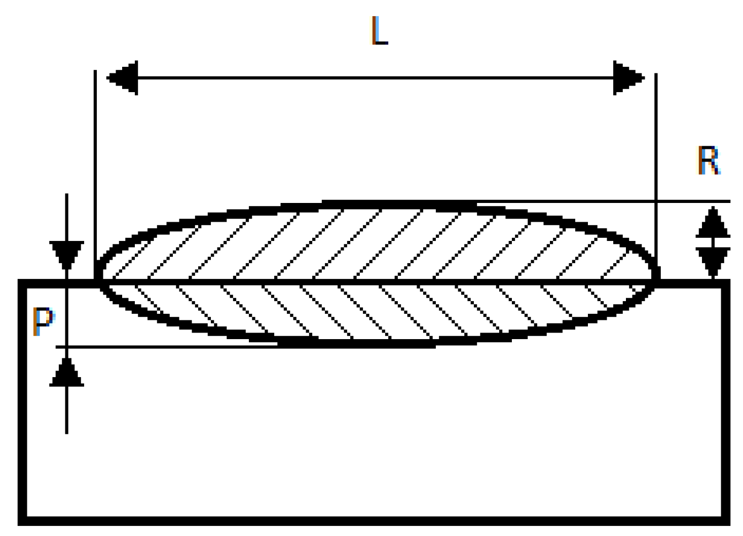
6]. As can be seen from
Figure 1 the letter P indicates penetration depth, L the bead width and R the reinforcement.
2.2. Processing Adjustments
To obtain a welding seam using the synergic MIG equipment, the parameters for the beginning and ending of the seam can be electronically controlled and, usually, are different from the rest of the welded seam. In this work were defined the main welding parameters for the two analyzed metal transfer types which are indicated in
Table 1. These parameters were maintained for all experimental tests, only changing the beginning and ending welding parameters.
In this work was used the welding equipment from Fronius
®, model Xplorer that allows the twelve parameters for the beginning and ending of the welding seam. The parameters are the gas pre-flow, the gas post-flow, feed speed, anti-adhesion correction, nominal gas value, gas factor, initial current, slope 1, final current, initial time, final time and slope 2. For each of these parameters were considered three levels and was neglected the interactions between them, in
Table 2 are represented the initial and final parameters with the respective levels.
2.3. Experimental Work
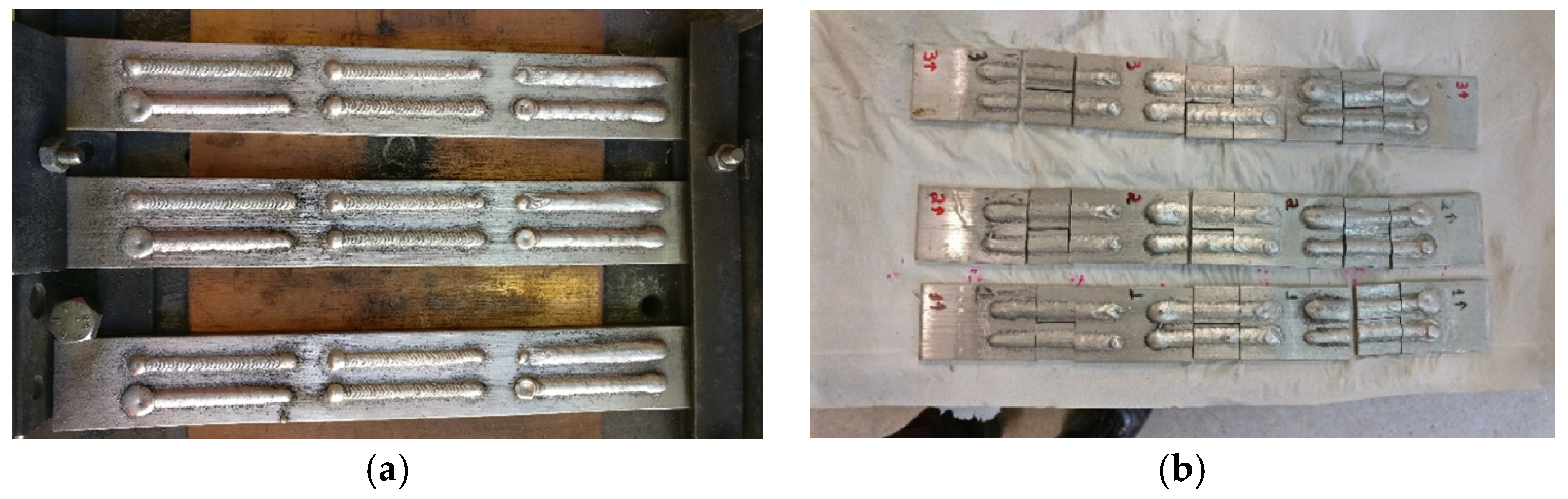
The objective was to evaluate and to optimize the penetration, bead width and reinforcement of robotized MIG welding in a 6082-T6 aluminum alloy sheet, 40 × 5 mm with the addition metal of Al 5754 with Ø 1 mm wire, see
Figure 2. For comparison purposes, Standard and CMT+P metal transfer types were analyzed.
2.4. Quality Control
The main goal of this work is to determine the optimal combination, in order to obtain the best possible welding quality. For the present work was defined that the quality is controlled by the welding penetration depth (P), the width of the weld bead (L) and reinforcement (R), showed in
Figure 3b. To accomplish the measurement of these parameters it is necessary to use a macroscopic experimental technique, which imposes the samples preparation (
Figure 3a).
The Taguchi method frequently uses a two-step optimization process. In first step uses the signal-to-noise ratio to determine the control factors that reduce variability. The second step, identifies the control factors that move the mean to target and have a small signal-to-noise ratio. The signal-to-noise ratio measures how the response varies relative to a target value under different noise conditions. For the present work were used two different targets, “nominal is best” (Equation (1)) for penetration and bead width and “smaller is better” (Equation (2)) for the reinforcement.
where
is the standard deviation,
n is the number of observations and
yi is the measured characteristic. Higher values of the signal-to-noise ratio identify the control factor settings that minimize the effects of the noise factors.
3. Results
In order to increase the scientific accuracy and to develop the statistical treatment of the results, reducing the chances of error, each test was repeated three times. As it is habitual for Taguchi experiments, the signal-to-noise ratio is calculated for the set of every three experiments from each of the 27 parameters combinations according to the formulas given above.
For reinforcement, was used the expression “smaller is better” (Equation (2)), where the purpose was to minimize the response, that is, as close as possible to zero. For the other two measurements, weld bead width and penetration, it is desirable to have equal or close to the thickness of the plate, which was five millimeters, which suggests a target response and therefore the formula is the “nominal is best” (Equation (1)). After determining the signal-to-noise ratio, for each of the 27 parameter combinations for Standard and CMT+P, the simple mean of the signal-to-noise values of each level, in its respective parameter, was taken.
Later, the graph of the mean signal-to-noise value of the parameters at each level was plotted, where a higher signal-to-noise value indicates the level with the best performance for each parameter. The combination of the 12 highest values in each parameter indicates the optimal combination to achieve the focus feature.
The methodology of analysis of variance (ANOVA) was applied, in the general linear model to verify the parameters of greater influence in the results for the desired characteristics. It was found that four parameters would not influence the quality of the weld. Thus, the post-gas flow, slope 2, final time and final flow were excluded from the ANOVA calculation. For the others, the calculations were performed normally.
The interpretation of the results after all these steps allowed to point out the optimal combination of parameters for a weld bead in relation to its width, penetration and reinforcement, as well as, the determination of the parameters that exert the strongest influence on the response.
The parameters and respective levels indicated as optimal for each of the desired characteristics, according to the mean values of the signal-to-noise ratio, were entered in the software of the welding machine (Fronius Xplorer) and the experimental tests of confirmation were carried out. This process gave rise to six new welding beads, these being the optimal width, penetration depth and reinforcement parameters for Standard and the optimal bead width, penetration depth and reinforcement parameters for CMT+P. Samples were prepared and three measurements were made using the same methodology.
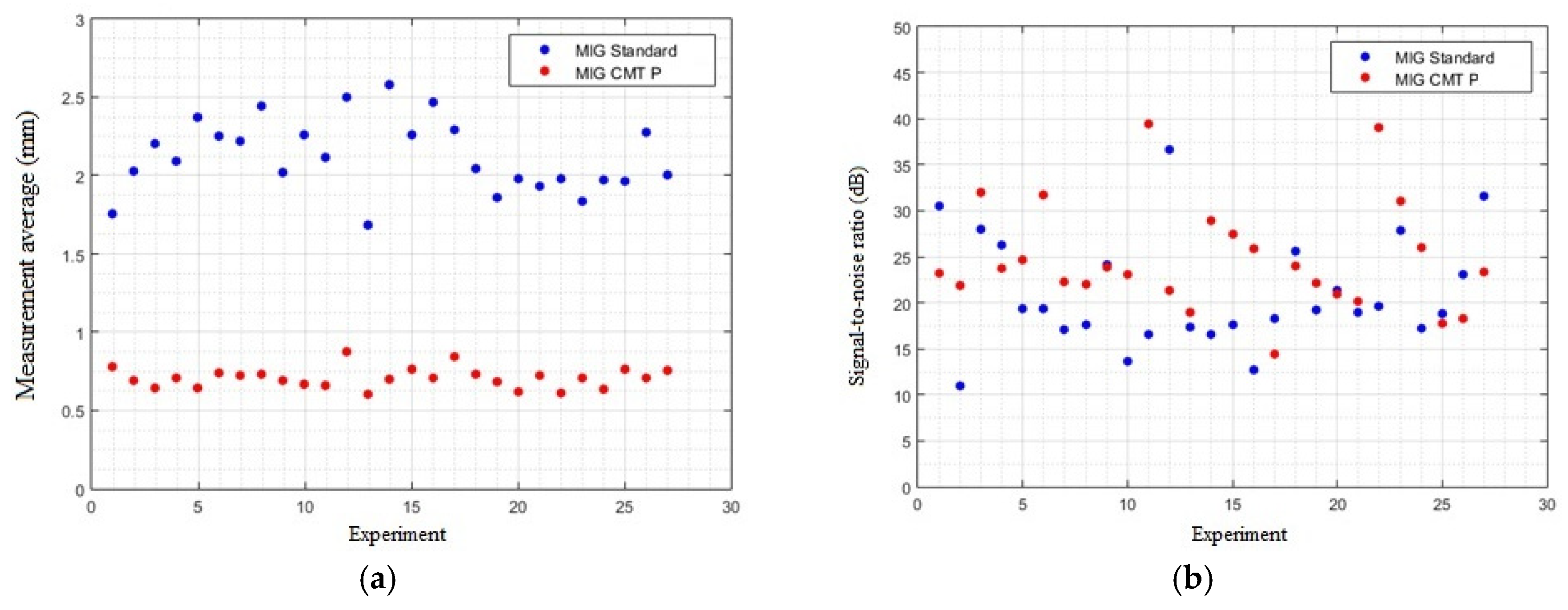
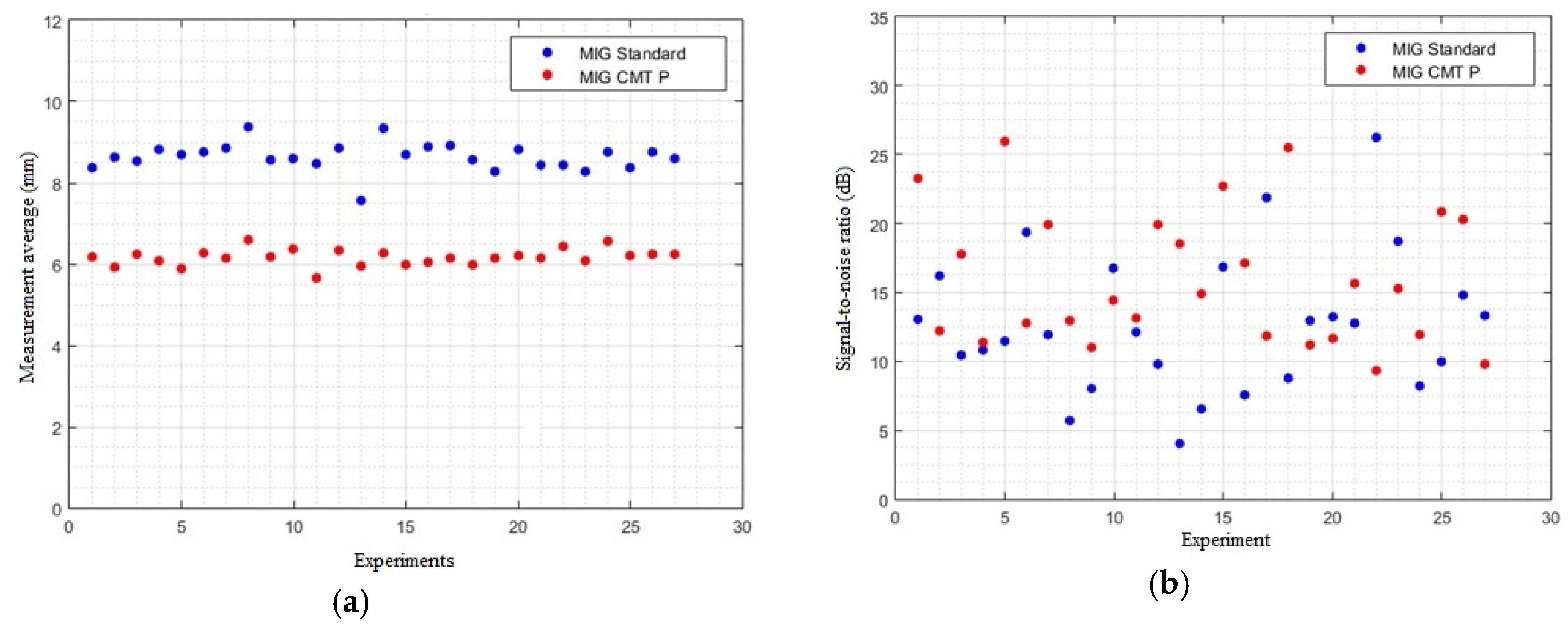
In
Figure 4,
Figure 5 and
Figure 6 is shown the values of average measurements (penetration depth, bead width and reinforcement) as well as the signal to noise ratio for each experiment (in a total of 27) and metal transfer type.
Observing the measurement of the control factors it is possible to verify that the penetration values are very different depending of the metal transfer, in the MIG standard (spray mode) the penetration is higher than the MIG CMT pulsed. However, for the bead width and reinforcement these differences are not so notable despite the tendency to corroborate the highest values for MIG standard. The signal-to-noise ratio values are very mixed for the penetration and bead width, on the other hand, in case of bead reinforcement is very clear the difference between the two types of metal transfer, being the MIG CMT pulsed with highest values of signal-to-noise ratio than the MIG standard.
The Taguchi method allows to obtain the optimal combination of welding parameters, however, it is necessary to be implemented confirmation experimental tests. In
Table 3,
Table 4 and
Table 5, is possible to remark measurement values (M1, M2 and M3), for the confirmation tests implemented in this work, for each optimal combination.
4. Conclusions
For the penetration depth, the method that presented the closest result to the desired and less prone to variability was the Standard method with the combination of parameters from experiment number 12 and for CMT+P was that of the confirmation experiment. For bead width the best result was for the CMT+P method in experiment 5 followed by the standard confirmation experiment. Already for the reinforcement, the best response was from experiment number 11 of the CMT method Pulsed and in sequence the standard confirmation experiment. Among the evaluated parameters within the processing settings, for the penetration depth, the nominal value of gas was proven to be a dominant factor in determining the result, appearing as more influential in both cases, MIG Standard and MIG CMT Pulsed. The dominance of the factor also extended the bead width, where it was the most influential for MIG CMT Pulsed and second place for MIG Standard. In the latter, the first placement was with slope 1, which appeared two times among the three most influential, both for width and penetration of the MIG CMT Pulsed method. In general, the geometry of the beads welded by the MIG Standard method are more suitable for joining welded joints, and the beads welded by the MIG CMT Pulsed method, due to the lower penetrations, more resemble a geometry desired for a weld coating.


