
Cyclic Thermal Shock Response of Zirconia/304 Stainless Steel Functionally Graded Materials Fabricated by Centrifugal Slurry Methods

Department of Mechanical Engineering, Graduate School of Science and Engineering, Hosei University, 3-7-2 Kajino-cho, Koganei-shi, Tokyo 184-8584, Japan
J. Compos. Sci. 2023, 7(2), 69; https://doi.org/10.3390/jcs7020069
Submission received: 3 January 2023
/
Revised: 18 January 2023
/
Accepted: 3 February 2023
/
Published: 7 February 2023
(This article belongs to the Section Composites Manufacturing and Processing)
Abstract
:Functionally graded materials (FGMs) are multi-phase composites with gradual spatial variations of constituents. The compositional transitions in the FGMs are classified into two manners such as continuous gradient manners and stepwise manners. In this study, zirconia (ZrO2)/ 304 stainless steel (SUS304) FGMs with continuous gradient manners were fabricated by a combination of centrifugal slurry methods and spark plasma sintering (SPS). A variety of continuous gradient patterns were achieved by controlling the amount of dispersant such as ammonium polycarboxylic acid (PCA) in the slurry. With an increase in the amount of PCA, the gradient patterns in the FGMs changed from ceramic (ZrO2)-rich to metal (SUS304)-rich ones. According to Stokes sedimentation velocity simulations, the sedimentation velocity of SUS304 particles is higher than that of ZrO2 particles. With an increasing amount of PCA, the sedimentation velocity of the particles decreases. Cyclic thermal shock test results demonstrated that FGMs with metal (SUS304)-rich continuous gradient patterns showed the highest resistance among the samples of FGMs, 5-layered materials and ZrO2 single materials.
1. Introduction
For the protection of structures working under high temperature and high temperature gradient conditions used in aerospace and automobile fields, ceramic/metal functionally graded materials (FGMs) can be of use and effectively applied. FGMs are multi-functional composites with gradual spatial variations of constituents, which result in a smooth variation of thermal, mechanical and electrical properties. Advantages of FGMs include smoothing of thermal stress distributions across the layers, minimization or elimination of stress concentrations and singularities at the interface corners and increase in bonding strength [1,2,3]. These features can be achieved by engineering the FGMs with a predetermined gradual spatial variation of the volume fractions and microstructure of the material constituents according to functional performance requirements [4,5].
Processes of fabrication of FGMs include a variety of techniques such as physical and chemical vapor depositions, plasma spray, thermal spray, cold spray coatings, centrifugal casting, centrifugal slurry and other powder metallurgical techniques [6,7,8]. FGMs have been recognized to have two manners of gradual transitions of properties from one side to another. One is a continuous gradient manner, and another is a stepwise manner [9]. Centrifugal techniques make a continuous gradient manner in the FGMs. Centrifugal casting can be performed by addition of hard particles to a molten metal and pouring the mixture into a rotating mold. The FGMs are solidified in the mold under centrifugal force producing the gradient of the hard particles in the metals, which depends on the size of particles, density and viscosity of the molten metal, the rate of solidification, mold rotational speed and others [10,11,12,13].
Centrifugal slurry methods were also carried out with slurry consisting of a mixture of ingredient powders and some liquids [9,11]. It is similar to centrifugal casting processes. The constituent ingredient materials are mixed in a liquid state and poured into a cylinder mold. Centrifugal force produces the gradient of the constituents in the materials due to differences in their densities and other factors when the mold is rotated. This process can be applied to fabricating ceramic/metal FGMs with a continuous gradient in accordance with predetermined distributions of specific characteristics. The advantage of using centrifugal slurry methods to centrifugal casting ones is that centrifugal slurry methods can be applied to a variety of materials without any consideration of their melting point. It was reported that such centrifugal slurry methods can be utilized for fabricating carbon nanotube (CNT) distributed aluminum FGMs using centrifugal slurry methods [9]. There has not been so much research investigating the relationship between the amount of dispersant in the solvent in the slurry and patterns of gradations of the constituents in the FGMs fabricated by centrifugal slurry methods.
Much attention has been paid to spark plasma sintering (SPS) as a superior powder consolidation technique for fabricating new types of materials in recent decades [14,15,16,17]. SPS places a direct current (DC) pulse directly into pressurized powder particles under vacuum conditions, which is advantageous for sintering of metals, ceramics, metallic glass, chemical reaction inorganic compounds and FGMs [18,19,20,21]. The vacuum conditions can prevent or limit the oxidation, whilst the fast-heating rates along spark plasma conditions inhibit unnecessary reactions between material powders, including suppressing coarse growth of formed phases and crystal grains [22]. Such fast heating as well as fast sintering at reduced temperatures can assist the consolidation of the FGMs without any change of compositional gradients in the materials. A combination of centrifugal slurry methods and SPS is considered to achieve excellent outcomes in obtaining smooth compositional gradients of constituent phases in the FGMs.
Thermomechanical behavior of ceramic/metal FGMs has been studied by many researchers [3,4,5,23,24,25]. It has been reported that the ceramic-rich side in FGMs is so brittle that cracking usually occurs from the ceramic surface into the inside of the FGMs, in particular, under unsteady heat-flow conditions such as thermal shock loadings [5,26,27]. As to the design and analysis of such FGMs, a micromechanics-based continuum model was formulated considering mechanisms of toughening of ceramics and their composites with stress-induced transformation of partially stabilized zirconia (PSZ) [5]. It was also reported that by taking into account time-dependent inelastic deformation (creep and diffusion around particles) and time-independent inelastic deformation (plasticity of metals) of the constituent phases, micro stresses in ceramic phases could be examined to determine the criteria of fracture of the FGMs. Dynamic analysis of multi-layered graded composite beams was conducted considering viscoelastic behavior of constituents [28,29]. Cyclic thermal shock tests have been used as useful and effective methods to understand thermomechanical behavior of the ceramic/metal FGMs under high temperature and high-temperature gradient conditions [30,31,32]. Experimental work has been also conducted, which demonstrated that under cyclic thermal shock conditions creep of ceramics during the heating stages brings large compressive stresses in the ceramic surface layers, which turns to large tensile stresses at the following stage of cooling, which possibly leads to the fracture of the ceramic-metal FGMs [4,25,33].
In this study, zirconia (ZrO2)/304 stainless steel (SUS304) FGMs were fabricated using a combination of centrifugal slurry methods and SPS. Slurry was composed of powders of ZrO2 and SUS304 with a dispersant such as ammonium polycarboxylic acid (PCA) in the solvent of water [34]. The fabricated samples were investigated on their microstructures and nano- and micro-mechanical properties to identify the compositional gradients in the FGMs. Stokes’s law was used to understand the formation of gradients of constituents in the FGMs. Resistance to cyclic thermal shock loadings was investigated in terms of crack propagations on the surfaces of ZrO2 and SUS304 of the samples. As a reference, multi-layered materials and ZrO2 single materials were also tested.
2. Experimental Procedure
2.1. Fabrication
SUS304 powder (Nilako Co., Ltd., Japan) with an average diameter of 100μm was sieved through a 400 mesh to obtain the powder with a diameter of 40μm or less. The sieved SUS304 powder and ZrO2 (partially stabilized zirconia, PSZ containing 3 mol % Y2O3) powder with a diameter of 62 nm (TZ-3Y-E, Tosoh Co., Ltd., Japan) were mixed. The volume ratio of SUS304 and ZrO2 powders was 6:4. The powders and a dispersant of ammonium polycarboxylic acid (PCA) (Aron A6114, Toa Synthetic Co., Ltd., Japan) were put together into distilled water (a solvent, Hayashi Jun Kogyo Co., Ltd., Japan). PCA mass ratio to the powders was 0, 1, 3, 5, 10 and 20%. Ultrasonic vibration treatments were carried out for 20 min to obtain a uniformly mixed powder slurry.
Figure 1 shows a photo and schematic illustration of centrifugal slurry equipment. The mixed powder slurry was poured into the mold. The rotational speed can be changed for a variety of levels of centrifugal forces. Centrifugal operations were performed at rotating speeds of 250, 500, 750 and 1000 rpm for 1800 s. After these operations, the slurry was dried in a drying oven at 150 °C for 8 h. The dried samples were pressed at 150 kN using a cold pressing machine to obtain green bodies. The green body sample was put into a graphite mold with an inner diameter of 20 mm and a height of 50 mm, which was set in the chamber (at 20 MPa) of a discharge plasma sintering (SPS) device (CSP-KIT-02121, S.S.Alloy Co., Ltd., Japan). The samples were sintered at 1100 °C for 10 min under the uniaxial pressure of 30 MPa, followed by cooling to 800 °C in 10 min, and then cooled to RT in the SPS chamber. Disk-shaped samples with a diameter of 20 mm and thickness of 3 mm were obtained as illustrated in Figure 2. As a reference, 4 types of layered and single material samples were also consolidated, such as 5-layered material samples, 3-layered material samples, 2-layered material samples and ZrO2 (PSZ) single material samples, which are illustrated in Figure 3. The layered material samples were prepared by stacking the mixed powders of ZrO2 and SUS 304 with different compositions in the state of slurry.
2.2. Materials Characterization
Microstructure observations accompanied with elemental analysis were performed using a scanning electron microscope (SEM, SU8020, Hitachi High-Technologies Co., Ltd., Japan) and energy dispersive X-ray spectroscopy (EDX, EMAX-Evolution, Horiba Ltd., Japan) with an acceleration voltage of 15 kV. The dwelling time was 5 μs. Figure 4 shows the spectrum in the cross section for element analysis by EDX, which is divided into 10 regions. Hardness tests were conducted using a Micro Vickers hardness tester (HM-200, Mitutoyo Co., Ltd., Japan) and nanoindentation tester (UNHT3HTV, Anton Paar Co., Ltd., Austria). The hardness and elastic modulus were probed in the cross sections of disk-shaped samples. The indentation test conditions are shown in Table 1. Figure 5 shows the measurement points for micro Vickers hardness and nanoindentation tests.
Cyclic thermal shock tests were conducted on the samples of ZrO2/SUS 304 FGMs and layered materials using the thermal shock test set-ups illustrated in Figure 6. The surfaces of ZrO2 were heated up to around 900 °C, and then the temperature was kept for 2 min, followed by cooling to room temperature (RT) in air. This heating and cooling process was repeated 30 times. After every heating and cooling process, in order to observe cracks initiating and propagating on the surfaces, the following procedure was carried out. The surfaces of ZrO2 and SUS 304 were wiped up with acetone for replica films to be attached to. The surface unevenness by cracks was transcribed onto the film. For investigating changes in mechanical properties on the surfaces of ZrO2 during the cyclic thermal shock tests, hardness and fracture toughness of the samples prior to and after cyclic thermal shock tests were measured using a Vickers hardness tester, mentioned above. Indentation fracture toughness, , was calculated by using the following equation, Equation (1) [9].
Here, is the fracture toughness
(),
the elastic modulus (Pa),
the Vickers hardness (Pa),
the indentation load (N),
the half of the average crack length (m),
the half of the average diagonal length of the indentation
().
3. Results and Discussion
3.1. Microstructures
Figure 7 shows SEM images of SUS304 and ZrO2 powders. It can be confirmed that the diameter of the SUS304 powder sieved through a 400 mesh is less than 50 μm. As for the ZrO2 powder, it can be seen in Figure 7d that the ZrO2 powder has uniform particle sizes of around 50 nm (62 nm in the specification). The ZrO2 powders tend to gather and form aggregations. It is seen in Figure 7c that spherical aggregations of ZrO2 powders with the sizes of around 20 to 40 μm can be detected. It is considered that such sizes of aggregations of ZrO2 powders significantly influence the centrifugal slurry processes to form gradients of constitutions in the FGMs as described later.
Now look at microstructures of the FGMs fabricated by centrifugal slurry methods. Figure 8 shows EDX results for samples with the rotating speed of 250 rpm for different amounts of PCA dispersant. Results of element mapping for Fe and Zr are shown, in which the red color represents Fe and the light blue color represents Zr. It is seen that in the sample without PCA (PCA (0%)), Fe and Zr are almost homogeneously distributed, while in the sample with PCA (1, 3, 5, 10 and 20%), distributions of Fe and Zr are divided into three parts: Fe parts, Zr parts and the interlayer, where the compositions continuously vary. The thickness and element distributions in the interlayer vary with the amount of PCA. It was mentioned in previous work [32] that macromolecules of PCA are adsorbed on the surface of the particles, which generate three-dimensional and electrostatic repulsive forces, which have the effect of dispersing and stabilizing the particles. Therefore, the states of dispersion or aggregation of particles depend on the amount of PCA. It is considered that the interlayers with continuously gradient compositions were formed because of difference in sedimentation rates of the particles, which is attributed to degree of the dispersion/ aggregation states of each particle due to addition of PCA [32].
Figure 9 shows distributions of Fe and Zr in centrifugal force directions, indicated by volume fractions, for the samples with the rotation speed of 250 rpm and 1000 rpm. As to the samples with the rotation speed of 250 rpm, for the sample without PCA, volume fraction of Fe sharply increases in 1 to 2 spectra, while the volume fraction of Zr sharply decreases correspondingly. As to the sample with PCA, in three to five of the spectra volume fraction of Fe and Zr continuously varies. Compositional gradient in the samples varies with amount of PCA. With an increasing amount of PCA, a remarkable increase of volume fraction of Fe can be seen in three to five spectra, while a corresponding decrease of volume fraction of Zr is seen in the spectra. In case of samples with a rotation speed of 1000 rpm, volume fraction of Fe varies in the different spectrum (position) for samples with different amounts of PCA. The amount of PCA can affect not only the gradient patterns in the compositional graded layers but also the positions of the graded layers in the materials. The gradient patterns for the samples with 1000 rpm are different from those for the samples with 250 rpm. It can be considered that addition of PCA can highly affect and possibly control compositional gradients as well as positions of the graded layers in the materials.
Figure 10 shows the volume fraction (%) of Fe as a function of the distance from ZrO2-rich surfaces in the spectra ranging from two to five in the centrifugal force directions (extracted from Figure 9a (bule and green areas)) with fitting curves expressed by the following Equation (2).
This equation can represent profiles of compositional gradients in the FGMs, which is characterized by the parameter of exponent n. Here,
and
are the volume fractions of Fe and Zr, respectively. is the distance from the ZrO2-rich surfaces. is the volume fraction of Fe. is the distance from the ZrO2-rich surfaces to the starting point of the graded layer, and is the distance from the ZrO2-rich surfaces to the ending point of the graded layer. In this calculation,
is 0 % at of 0.6 mm, and is 90% at of 1.2 mm. It is seen in Figure 10 that n = 1 indicates a linear compositional gradient, n < 1 indicates ceramic-rich gradients and n > 1 indicates metal-rich gradients. It is seen that with an increase in the amount of PCA from 1 to 20%, FGMs with the rotating speed of 250 rpm shows more metal (Fe)-rich gradients, which corresponds to an increase of n. As seen in Figure 10, FGMs with PCA (5%) show an almost linear gradient, that is, n = 1. The FGMs with PCA (more than 5%) show ceramic (Zr)-rich gradients (n < 1), while the FGMs with PCA (less than 5%) show metal (Fe)-rich gradients (n > 1). FGMs without PCA show no compositional gradient layer. It can be seen that compositional gradients in the FGMs can be controlled from n~0.5 to 3 with PCA (from 1% to 20%).
3.2. Indentation Properties
Figure 11 shows optical microscope images of residual indentation impressions for micro Vickers hardness and nanoindentation. It can be seen in Figure 11 that the sizes of the impressions differ between the Vickers hardness and the nanoindentation, in which the impression of Vickers hardness covers the large area of both SUS and ZrO2 phases, while the impression of nanoindentation can be only present in each phase. It is considered that Vickers hardness can estimate the mechanical properties of representative volume of the composites, which can be a building block of the FGMs. Meanwhile, nanoindentation can estimate the mechanical properties of each constitutive phase of the composites.
Figure 12 shows Vickers hardness varying in centrifugal directions in the cross sections in the samples with the rotation speed of 250 and 500 rpm for variety of amount of PCA. It is seen in Figure 12 that Vickers hardness in the cross sections in the samples varies (decreases) drastically in the 0 to 6 mm distance (corresponding to one to three spectra in Figure 4). Vickers hardness of ZrO2 and SUS304 in literature are 1250 and 200 HV, respectively. This decrease in Vickers hardness is considered to represent the change in compositions in the samples, which is shown in Figure 9.
Figure 13 shows nanoindentation hardness in cross sections in centrifugal force directions in the samples with rotation speeds of 250 and 1000 rpm for a variety of amounts of PCA. This nanoindentation hardness is an average value for each measurement area as shown in Figure 5b. It is seen that the nanoindentation hardness at the position of 0~0.8 mm is higher than that at the position of more than 1 mm from ZrO2-rich surfaces, which means that higher nanoindentation hardness results from higher contents of ZrO2. Consequently, from the experimental results as shown in Figure 8, Figure 9, Figure 10 and Figure 12, addition of PCA can control the degree of gradients of constituents in the FGMs.
3.3. Cyclic Thermal Shock Behavior
Cyclic thermal shock response was examined. Figure 14 shows the relation between the total length of cracks on ZrO2-rich surfaces and the number of thermal shock cycles. Figure 15 shows the photos of samples and replica films reflecting crack propagations, which are represented by red lines, on ZrO2-rich surfaces of the samples of the FGMs, 5-layered materials and ZrO2 single-layer materials before thermal shock tests, after 15 thermal shocks and after 30 thermal shocks. Regarding 3-layerd and 2-layered (cladding) materials, these were fractured during the SPS sintering processes, whose photos are shown in Figure 16. This fracture can occur due to thermal stresses generated under the thermo-mechanical (deformation constrained by the carbon die) boundary conditions during the SPS processes.
It is seen in Figure 14 and Figure 15 that there is no damage (no crack) on the ZrO2-rich surfaces in FGMs with PCA (20%) after 30 thermal shocks. Meanwhile, for FGMs with PCA (5%), relatively large cracks generated even just after the fabrication. For FGMs with PCA (0% and 5%) and 5-layered materials, cracks propagated as the number of cyclic thermal shocks increased. For FGMs with PCA (0% and 5%), the total length of cracks reached more than 120 mm after 30 thermal shocks. FGMs with PCA (5%) showed a small size of crack just after the fabrication. However, when the FGMs with PCA (5%) start to be subject to cyclic thermal shocks, cracks grow rapidly at the beginning of the cyclic thermal shock loadings (less than 3 cycles). The samples of 5-layered materials showed a total crack length of greater than 60 mm on ZrO2-rich surfaces just after the fabrication, which is greater than that of the samples of the FGMs, although after 30 thermal shocks, the total crack length of the samples of 5-layered materials was smaller than those of FGMs with PCA (0% and 5%). As for ZrO2 single-layer materials, there was no crack just after the fabrication.
Here, consider the thermal stress states in the materials during the cyclic thermal shock tests. On the ZrO2-rich surfaces heated, the ZrO2 surface layer thermally expanded, leading to the in-plane compressive stresses generated in the ZrO2 surface layer. The in-plane compressive stresses can make the ZrO2 layer undertake compressive creep. Just at the start of cooling, the states of in-plane stresses in the ZrO2 surface layer change from compressive to tensile. The maximum in-plane tensile stresses in the ZrO2 surface layer can be reached just after the start of cooling [4]. Such tensile stresses in the ZrO2 surface layer cause fracture of the ZrO2 surface layer. For ZrO2 single-layer materials, such tensile stresses can make cracks generate from the heated surface and propagate into the materials, which leads to fracture of the whole materials splitting in half as shown in Figure 15. It is considered that compositional gradients in the FGMs and 5-layered materials can contribute to reduce such thermal stresses compared to ZrO2 single-layer materials. Regarding distributions of cracks propagating on ZrO2-rich surfaces as shown in Figure 15, for FGMs with PCA (0% and 5%) and 5-layerd materials, cracks generated in the outer portions during the fabrication processes and at the beginning of the cyclic thermal shocks. With an increase in the number of thermal shock cycles, network-like cracks were developed on ZrO2-rich surfaces of the FGMs with PCA (0% and 5%). Regarding the SUS304-rich surfaces, there was no crack generated from the fabrication to the (final) 30th thermal shock for all the samples of FGMs with PCA (0%, 5% and 20%) and 5-layered materials.
Next, the changes in mechanical properties of the samples during cyclic thermal shock tests are focused on. Figure 17 shows Vickers hardness on the ZrO2-rich surfaces of the FGMs with PCA (0%, 5% and 20%), 5-layered materials and ZrO2 single-layer materials before and after cyclic thermal shock tests. It is seen that the hardness of the samples after cyclic thermal shock tests was slightly lower than those of the samples before the cyclic thermal shock tests. This is because in-plane tensile stresses were generated and remain in the ZrO2-rich surface layer after cooling processes in cyclic thermal shock tests, which can make the apparent hardness lower. In addition, the hardness of the ZrO2-rich surfaces of the FGMs with PCA (0%, 5% and 20%) and 5-layered materials was lower than that of ZrO2 samples. It is considered that the ZrO2-rich surfaces of the FGMs with PCA (0%, 5% and 20%) and 5-layered materials may contain SUS304 in the ZrO2-rich surface layer.
Figure 18 shows SEM images of indentation impressions on ZrO2-rich surfaces of samples of the FGMs with PCA 20%. There are cracks at the edges of the impressions on the samples after the cyclic thermal shock tests, while there is no crack around indentation impressions for the samples before the cyclic thermal shock tests. Such indentation-induced cracks can appear in all the samples after the cyclic thermal shock tests. It is considered that fracture toughness was lowered by the cyclic thermal shock loadings. Toughening can be achieved by stress-induced transformation from tetragonal to monoclinic crystal structures at the tips of cracks in PSZ. It can be considered that the samples after the cyclic thermal shock tests have residual in-plane tensile thermal stresses in the ZrO2-rich surface layer generated during the cooling processes in cyclic thermal shock tests, which leads to crack propagation on the ZrO2-rich surfaces. Furthermore, the phase transformation from tetragonal to monoclinic crystal structures of PSZ can be promoted during the cyclic thermal shock tests, which may incur the effect of transformation toughening by PSZ in the ZrO2-rich surface layer being lowered after the cyclic thermal shock tests.
Figure 19 shows fracture toughness of the samples of FGMs with PCA (0%, 5% and 20%), 5-layered materials and ZrO2 materials after the cyclic thermal shock tests, which is calculated from the length of cracks as shown in Figure 18 using Equation (1). It can be seen that FGMs with PCA (5% and 20%) and 5-layered materials showed higher fracture toughness than ZrO2 single phase materials. It is considered that compositional gradient in the FGMs and 5-layered materials can contribute to the reduction of thermal stresses causing stress-induced transformation during the cyclic thermal shock tests, which leads to keeping the initial high fracture toughness of the ZrO2-rich surface layer prior to cyclic thermal shock tests.
4. Stokes Sedimentation Velocity Simulation
At this point, a simulation was conducted to examine formation of compositional gradations in the FGMs under centrifugal force conditions. The sedimentation velocity of particles in a viscous liquid under a centrifugal force can be expressed by the Stokes sedimentation velocity equation as given by Equation (3). The relative centrifugal acceleration G in Equation (3) can be expressed by Equation (4) [9].
Here, ρs is the density of the particles, ρ is the density of the fluid, d is the particle diameter, μ is the viscosity of the fluid, D/2 is the radius of rotation and N is the number of rotations. From Equations (3) and (4), the velocity of particles is proportional to the difference in density between slurry and particles, the square of the diameter of the particles, and the square of the number of revolutions, and is inversely proportional to the viscosity of the fluid.
Densities and particle sizes of SUS304 and ZrO2 are shown in Table 2. Densities and viscosities of solvent and dispersant are shown in Table 3. The states of aggregations of ZrO2 powers were also taken into account. Using these states of aggregations, sedimentation velocities of SUS304 powders and ZrO2 powders and aggregations were calculated. The results are shown in Figure 20. The viscosity of the fluid consisting of water and PCA were calculated based on the assumption that this obeys the rule-of-mixture.
From the simulation results shown in Figure 20, the sedimentation velocity of SUS304 is higher than that of ZrO2. It is considered that SUS304 powders with higher sedimentation velocity move more quickly than ZrO2 powders in the direction of centrifugal forces. This deference in velocity of the ingredient powders can produce continuous gradients of compositions in the interlayer in the samples, that is, forming the layer of the FGMs. It is seen in Figure 20 that addition of PCA significantly affects the sedimentation velocity of the particles. As seen in Table 3, the viscosity of PCA is much higher than that of distilled water, which leads to a decrease of sedimentation velocity of the particles by adding PCA to the water as shown in Figure 20, which is consistent with Equation (3). As seen in Figure 7c,d, the ZrO2 powders can aggregate, and the shape of the aggregation is considerably high sphericity with a diameter of around 20 to 40 μm. It can be seen in Figure 20b that the sedimentation velocity of aggregated ZrO2 powders is very high compared to that of non-aggregated ZrO2 powders, which is close to that of SUS304 powders. This is because the velocity highly depends on sizes of particles (proportional to the square of the diameters of the particles) as expressed by Equation (3). It can be also said that addition of an excessive amount of PCA into solvent causes a phenomenon called interference sedimentation. Interference sedimentation is a phenomenon in which the sedimentation velocity of particles slows down due to the interaction of the particles. This phenomenon can reduce the difference in sedimentation velocity between SUS304 and ZrO2 particles, resulting in producing a continuous composition gradient in the materials [6]. It can be concluded that by changing the sizes of particles, including states of aggregations of ZrO2 particles and the amount of PCA dispersant in solvent, the gradient of compositions in the interlayer of FGMs can be controlled.
5. Discussion
A combination of centrifugal slurry methods and SPS is effective in producing continuous compositional gradients in two-phase composites. Centrifugal slurry methods can be applied to form FGMs with a variety of ingredient material powders. The selection of ingredient materials, taking account of density, size of the powders, and the amount of PCA as a dispersant, can be conducted to control and obtain preferred compositional gradients in the materials. As described in the introduction, SPS can provide high heating rates and be an efficient sintering technique to make a quick consolidation of ingredient powders at low temperatures, so as to obtain high densities combined with fine and uniform grains. These can suppress extensive atomic diffusions and prevent changes in compositional gradients, formed in the centrifugal slurry processes, during the consolidation processes.
As seen in Figure 8, Figure 9 and Figure 10, the amount of PCA in a slurry highly affects compositional gradient patterns formed in the FGMs, for which a higher amount of PCA tends to bring about a lower value of the gradient parameter of n, that is, metal-rich gradients in the FGMs with the rotating speed of 250 rpm, as shown in Figure 10. The compositional gradients were also affected by rotating speeds in the centrifugal processes that can be connected to centrifugal forces. In the current study, the rotating speeds of 250, 500, 750 and 1000 rpm in centrifugal procedures were applied to investigate the effect of centrifugal forces on forming compositional gradient patterns, whose results demonstrated that FGMs with the rotating speeds of 250 and 500 had gradual compositional variations in some positions in the materials, while FGMs with the rotating speeds of 750 and 1000 rpm showed relatively sharp compositional variations in wide ranges of positions in the FGMs with a variety of the amount of PCA.
As shown in Figure 20 and expected from Equations (3) and (4), the sedimentation velocities of powders of ZrO2 and SUS 304 are highly affected by the amount of PCA and level of centrifugal forces. With increasing the amount of PCA, the sedimentation velocities of powders of ZrO2 and SUS 304 decrease. In the experiment, for FGMs with the rotating speeds of 250 rpm, metal (Fe)-rich compositional gradients (n < 1) were produced in the FGMs with PCA (higher than 5%) as shown in Figure 10. It can be considered that there is a possibility that PCA also affects the states of aggregations of ZrO2 particles, for which a higher amount of PCA may produce larger aggregations of ZrO2 particles. It can be concluded that a combination of centrifugal slurry methods and SPS can produce FGMs with continuous compositional gradient patterns. Compositional gradient patterns can be controlled by changing the amount of PCA in the slurry. In addition, during the centrifugal slurry processes, the rotating speeds and rotating time can also highly affect formed compositional gradient patterns as well as positions and thickness of the graded layers in the materials.
Discuss the effect of compositional gradients formed by centrifugal slurry methods on cyclic thermal shock behavior of the FGMs. It can be advantageous to insert or produce compositional gradient layers in cladding (2-layered) materials which are not fractured under large temperature gradient conditions as well as uniform temperature change conditions. In this study, in the processes of fabrication by SPS, 2-layered and 3-layered materials were fractured, for which cracks propagated at the interface between the ZrO2 surface layer and the next layer or in the ZrO2 surface layer as shown in Figure 16. When the cyclic thermal shock tests were conducted, in which the thermal shocks were only applied to ZrO2-rich surfaces, cracks appeared only on ZrO2-rich surfaces, but not on SUS304-rich surfaces, for all the samples. As seen in Figure 15, FGMs made by centrifugal slurry methods show higher resistance to cyclic thermal shock loadings compared to 5-layered materials. It is considered that continuous compositional gradient patterns are more effective than stepwise compositional gradient patterns to protect the materials and structures under cyclic thermal shock conditions at high temperatures and/or under high temperature gradient conditions.
Regarding the effect of compositional gradient patterns formed by centrifugal slurry methods on capability of resistance to cyclic thermal shock loadings, the FGMs with a rotating speed of 250 rpm were investigated. As shown in Figure 10, by changing the amount of PCA (1~20%) in a slurry, it is possible to control the compositional gradient patterns from ceramic (Zr)-rich gradient patterns (n = 0.5) to metal (Fe)-rich gradient patterns (n = 3). In a previous study, it was reported about cyclic thermal shock resistance of ZrO2-Ti FGMs, ZrO2-Ni FGMs and others that the FGMs with metal-rich compositional gradient patterns showed higher resistance to cyclic thermal shock loadings compared to the FGMs with linear or ceramic-rich gradient patterns [4,25]. As already mentioned, during cyclic thermal shock tests, creep of ZrO2 at high temperatures on heating or keeping high temperatures highly affects thermal stress states in the ZrO2 surface layer at the subsequent cooling stage, that is, high in-plane tensile stresses generated in the ZrO2-rich surface layers [4,25,31]. Although only crack propagations on the surface layers were examined in the current study, it may also be important to probe the crack propagating into the materials, which directly leads to the fracture.
It can be concluded that centrifugal slurry methods are very effective at producing the high-performance FGMs with superior resistance to cyclic thermal shock loadings, which have continuous and pre-determined compositional gradient patterns. Extensive investigation will be needed to make a clear relation between the sedimentation velocities of powders of ingredient materials and the amount of PCA to control compositional gradient patterns more precisely.
6. Conclusions
ZrO2/ SUS304 FGMs were fabricated by a combination of centrifugal slurry methods and spark plasma sintering (SPS). Compositional gradient patterns in the FGMs can be controlled by changing the amount of PCA in a slurry and the centrifugal forces. The fabricated FGMs were studied on microstructures and nano- and micro hardness, as well as cyclic thermal shock resistance. The summary is described below.
- From the results of Zr and Fe distributions obtained by SEM EDX analysis, it was seen that by changing the amount of PCA in a slurry, continuous compositional gradient patterns can be achieved, for which a large amount of PCA (20%, which is an weight percent to mixed powders) produced a metal (SUS304)-rich gradient pattern, a moderate amount of PCA (5%) produced a linear gradient pattern, and a small amount of PCA (3%) produced a ceramic (ZrO2)-rich gradient pattern. Adding an appropriate amount of PCA creates a dispersing/ aggregating state of particles and alleviate the difference in sedimentation rates. Rotating speeds connected to centrifugal forces in centrifugal slurry processes also highly affect forming of compositional gradients in the FGMs. Micro Vickers and nanoindentation hardness distributions corresponds to element distributions analyzed by EDX. Stokes’s law simulation enabled us to understand the centrifugal slurry processes which produce the continuous compositional gradient patterns, considering aggregations of ZrO2 particles.
- Cyclic thermal shock test results demonstrated that FGMs with metal (SUS304)-rich continuous gradient patterns produced with PCA (20%) showed the highest resistance to cyclic thermal shock loadings among the samples of FGMs, 5-layered materials and ZrO2 single-layer materials. No crack appeared on ZrO2-rich surfaces in the samples of the FGMs with metal (SUS304)-rich continuous gradient patterns after 30 cyclic thermal shocks. Continuous compositional gradients were essential to reduce thermal stresses generated not only in fabrication processes but also under subsequent cyclic thermal shock loading conditions. Vickers hardness on the ZrO2-rich surfaces of the FGMs, 5-layered materials and ZrO2 materials slightly decreased after cyclic thermal shock tests. This may result from in-plane tensile stresses generated and remained in the ZrO2-rich surface layer after cyclic thermal shock tests. Fracture toughness on the ZrO2-rich surface also decreased because stress-induced transformation may have occurred during the cyclic thermal shock tests. FGMs with PCA (5% and 20%) and 5-layered materials showed higher fracture toughness than ZrO2 single-layer materials.
Funding
This research received no external funding.
Acknowledgments
The author is thankful to Yusei Takemoto and Yuto Imai for their assistance in experimental work.
Conflicts of Interest
The author declares no conflict of interest or personal relationships that could have appeared to influence the work reported in this paper.
References
- Chen, Y.; Erdogan, F. The interface crack problem for a nonhomogeneous coating bonded to a homogeneous substrate. J. Mech. Phys. Solids 1996, 44, 771–787. [Google Scholar] [CrossRef]
- Kim, J.-H.; Paulino, G.H. An accurate scheme for mixed-mode fracture analysis of functionally graded materials using the interaction integral and micromechanics models. Int. J. Numer. Methods Eng. 2003, 58, 1457–1497. [Google Scholar] [CrossRef]
- Tsukamoto, H. Analytical method of inelastic thermal stresses in a functionally graded material plate by a combination of micro- and macromechanical approaches. Compos. Part B Eng. 2003, 34, 561–568. [Google Scholar] [CrossRef]
- Tsukamoto, H. Design of functionally graded thermal barrier coatings based on a nonlinear micromechanical approach. Comput. Mater. Sci. 2010, 50, 429–436. [Google Scholar] [CrossRef]
- Tsukamoto, H. Design against fracture of functionally graded thermal barrier coatings using transformation toughening. Mater. Sci. Eng. A 2010, 527, 3217–3226. [Google Scholar] [CrossRef]
- Pasha, A.; Rajaprakash, B.M. Fabrication and mechanical properties of functionally graded materials: A review. Mater. Today Proc. 2022, 52, 379–387. [Google Scholar] [CrossRef]
- Guo, W.; Jiang, Z.; Zhang, C.; Zhao, L.; Jiang, Z.; Li, X.; Chen, G. Fabrication process of smooth functionally graded materials through a real-time inline control of the component ratio. J. Eur. Ceram. Soc. 2021, 41, 256–265. [Google Scholar] [CrossRef]
- Singh, R.K.; Rastogi, V. A review on solid state fabrication methods and property characterization of functionally graded materials. Mater. Today Proc. 2021, 47, 3930–3935. [Google Scholar] [CrossRef]
- Tsukamoto, H. Tribological Characterization of Carbon Nanotube/Aluminum Functionally Graded Materials Fabricated by Centrifugal Slurry Methods. J. Compos. Sci. 2021, 5, 254. [Google Scholar] [CrossRef]
- El-Galy, I.M.; Ahmed, M.H.; Bassiouny, B.I. Characterization of functionally graded Al-SiCp metal matrix composites manufactured by centrifugal casting. Alex. Eng. J. 2017, 56, 371–381. [Google Scholar] [CrossRef]
- Ogawa, T.; Watanabe, Y.; Sato, H.; Kim, I.-S.; Fukui, Y. Theoretical study on fabrication of functionally graded material with density gradient by a centrifugal solid-particle method. Compos. Part A 2006, 37, 2194–2200. [Google Scholar] [CrossRef]
- Chumanov, I.; Anikeev, A.; Chumanov, V. Fabrication of Functionally Graded Materials by Introducing Wolframium Carbide Dispersed Particles During Centrifugal Casting and Examination of FGM’s Structure. Procedia Eng. 2015, 129, 816–820. [Google Scholar] [CrossRef]
- Rajan, T.; Pillai, R.; Pai, B. Characterization of centrifugal cast functionally graded aluminum-silicon carbide metal matrix composites. Mater. Charact. 2010, 61, 923–928. [Google Scholar] [CrossRef]
- Hong, C.-Q.; Zhang, X.-H.; Li, W.-J.; Han, J.-C.; Meng, S.-H. A novel functionally graded material in the ZrB2–SiC and ZrO2 system by spark plasma sintering. Mater. Sci. Eng. A 2008, 498, 437–441. [Google Scholar] [CrossRef]
- Luo, Y.; Pan, W.; Li, S.; Wang, R.; Li, J. A novel functionally graded material in the Ti–Si–C system. Mater. Sci. Eng. A 2003, 345, 99–105. [Google Scholar]
- Zhang, Z.; Shen, X.; Zhang, C.; Wei, S.; Lee, S.; Wang, F. A new rapid route to in-situ synthesize TiB–Ti system functionally graded materials using spark plasma sintering method. Mater. Sci. Eng. A 2013, 565, 326–332. [Google Scholar] [CrossRef]
- Tang, X.; Zhang, H.; Du, D.; Qu, D.; Hu, C.; Xie, R.; Feng, Y. Fabrication of W–Cu functionally graded material by spark plasma sintering method. Int. J. Refract. Met. Hard Mater. 2014, 42, 193–199. [Google Scholar] [CrossRef]
- Tsukamoto, H. MicrostructureandindentationpropertiesofZrO2/Ti functionally graded materials fabricated by spark plasma sintering. Mater. Sci. Eng. A 2015, 640, 338–349. [Google Scholar] [CrossRef]
- Lee, S.-H.; Tanaka, H.; Kagawa, Y. Spark plasma sintering and pressureless sintering of SiC using aluminum borocarbide additives. J. Eur. Ceram. Soc. 2009, 29, 2087–2095. [Google Scholar] [CrossRef]
- Watanabe, M.; Yokoyama, K.; Imai, Y.; Ueta, S.; Yan, X.L. Spark plasma sintering of SiC/graphite functionally graded materials. Ceram. Int. 2022, 48, 8706–8708. [Google Scholar] [CrossRef]
- Morin, C.; Le Gallet, S.; Ariane, M.; Bernard, F. Spark Plasma Sintering tool design for preparing alumina-based Functionally Graded Materials. Ceram. Int. 2016, 42, 3056–3063. [Google Scholar] [CrossRef]
- Muhammad, W.N.A.W.; Sajuri, Z.; Mutoh, Y.; Miyashita, Y. Microstructure and mechanical properties of magnesium composites prepared by spark plasma sintering technology. J. Alloys Compd. 2011, 509, 6021–6029. [Google Scholar] [CrossRef]
- Nojumi, M.M.; Wang, X. Analysis of crack problems in functionally graded materials under thermomechanical loading using graded finite elements. Mech. Res. Commun. 2020, 106, 103534. [Google Scholar] [CrossRef]
- Zhang, Y.; Guo, L.; Wang, X.; Shen, R.; Huang, K. Thermal shock resistance of functionally graded materials with mixed-mode cracks. Int. J. Solids Struct. 2019, 164, 202–211. [Google Scholar] [CrossRef]
- Tsukamoto, H. Microwave-enhanced consolidation of zirconia/titanium functionally graded materials. Mater. Sci. Eng. B 2021, 274, 115464. [Google Scholar] [CrossRef]
- Hein, J.; Storm, J.; Kuna, M. Numerical thermal shock analysis of functionally graded and layered materials. Int. J. Therm. Sci. 2012, 60, 41–51. [Google Scholar] [CrossRef]
- Han, J.-C.; Wang, B.-L. Thermal shock resistance enhancement of functionally graded materials by multiple cracking. Acta Mater. 2006, 54, 963–973. [Google Scholar] [CrossRef]
- Qaderi, S.; Ebrahimi, F.; Vinyas, M. Dynamic analysis of multi-layered composite beams reinforced with graphene platelets resting on two-parameter viscoelastic foundation. Eur. Phys. J. Plus 2019, 134, 339–349. [Google Scholar] [CrossRef]
- Ebrahimi, F.; Qaderi, S. Stability analysis of embedded graphene platelets reinforced composite plates in thermal environment. Eur. Phys. J. Plus 2019, 134, 349–363. [Google Scholar] [CrossRef]
- Tsukamoto, H. Micromechanical Simulation of Thermal Cyclic Behavior of ZrO2/Ti Functionally Graded Thermal Barrier Coatings. Coatings 2015, 5, 63–77. [Google Scholar] [CrossRef]
- Yanga, Z.; Yuanb, H.; Liub, H. Evolution and characterization of cyclic thermal shock-induced thermomechanical damage in oxide/oxide ceramics matrix composites. Int. J. Fatigue 2019, 120, 150–161. [Google Scholar] [CrossRef]
- Gan, Z.; Ng, H.W. Experiments and inelastic finite element analyses of plasma sprayed graded coatings under cyclic thermal shock. Mater. Sci. Eng. A 2004, 385, 314–324. [Google Scholar] [CrossRef]
- Kawasaki, A.; Watanabe, R. Thermal fracture behavior of metal/ceramic functionally graded materials. Eng. Fract. Mech. 2002, 69, 1713–1728. [Google Scholar] [CrossRef]
- Kitamura, K.; Mochizuki, Y.; Mori, T. Study on particle dispersion changes over time in aqueous Al2O3 slurries containing ammonium polyacrylate. Colloids Surf. A Physicochem. Eng. Asp. 2021, 622, 126623. [Google Scholar] [CrossRef]
Figure 1.
Centrifugal slurry equipment ((a) apparatus photo and (b) schematic illustrations).
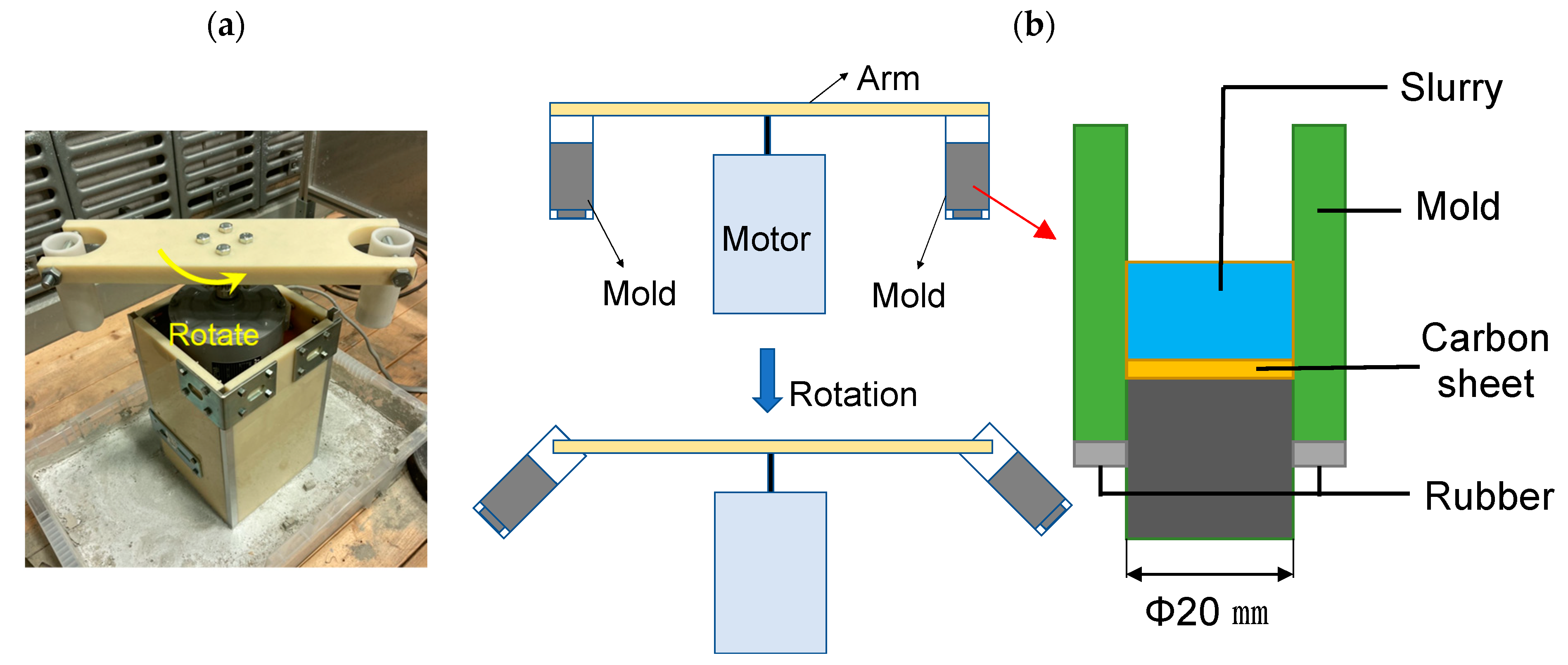
Figure 2.
Schematic illustration of a sample of FGMs made by centrifugal slurry methods.

Figure 3.
Schematic illustrations of multi- and single-layered materials. (a) 5-layered materials, (b) 3-layered materials, (c) 2-layered (cladding) materials and (d) ZrO2 single-layer materials.
Figure 3.
Schematic illustrations of multi- and single-layered materials. (a) 5-layered materials, (b) 3-layered materials, (c) 2-layered (cladding) materials and (d) ZrO2 single-layer materials.
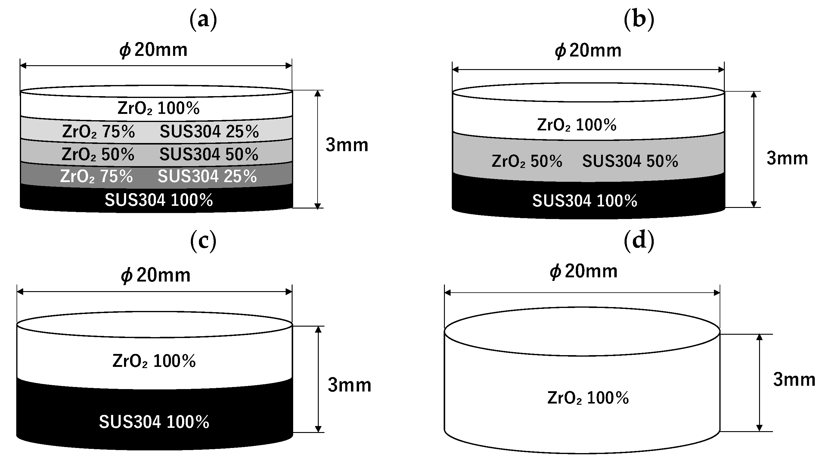
Figure 4.
Spectrum for element analysis by EDX.
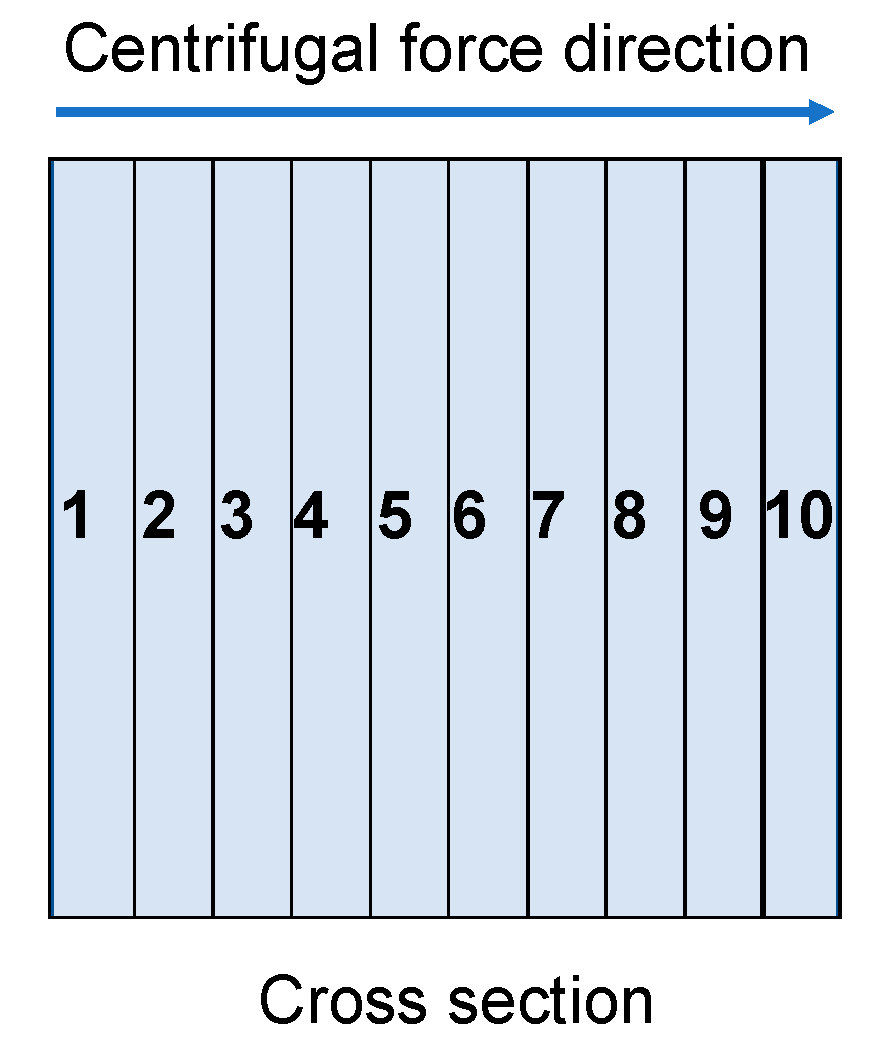
Figure 5.
Hardness testing points for (a) Micro Vickers hardness test, and (b) Nanoindentation test.
Figure 5.
Hardness testing points for (a) Micro Vickers hardness test, and (b) Nanoindentation test.
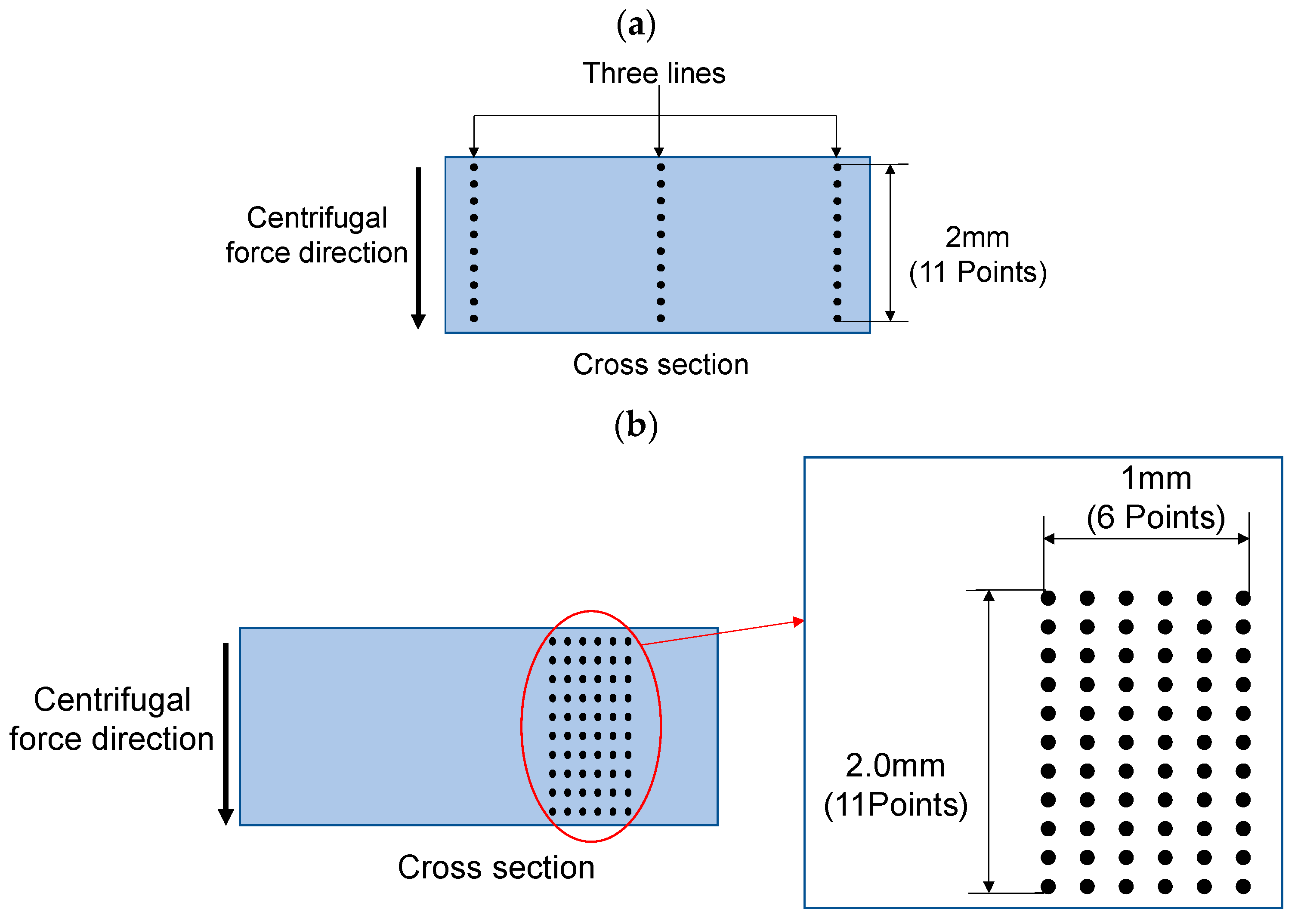
Figure 6.
Cyclic thermal shock test set-ups. (a) photo and (b) illustration.
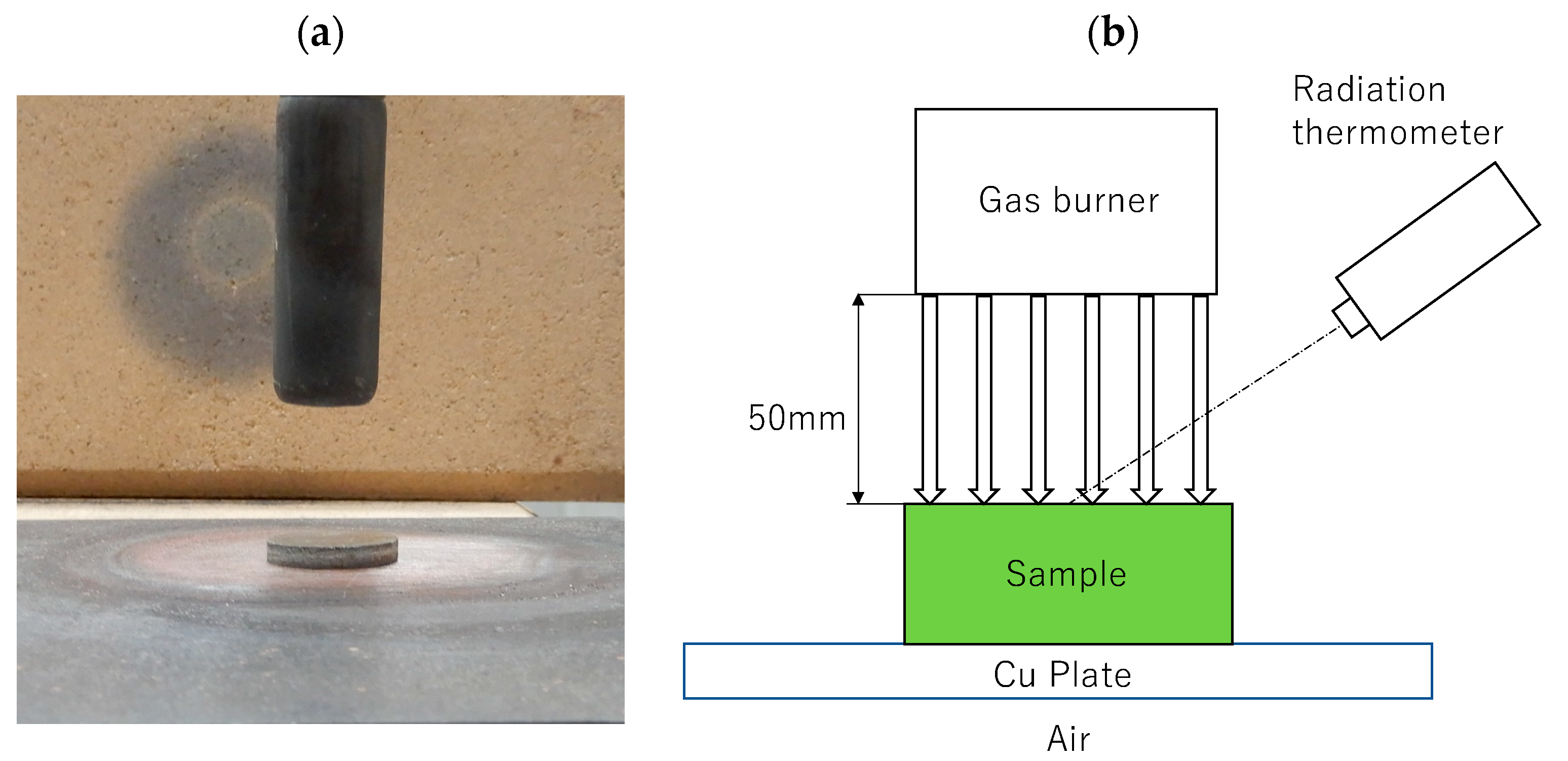
Figure 7.
SEM images of SUS304 powders sieved through a 400 mesh (a,b) and ZrO2 powders (c,d). (a,c) are low magnification images and (b,d) are high magnification images.
Figure 7.
SEM images of SUS304 powders sieved through a 400 mesh (a,b) and ZrO2 powders (c,d). (a,c) are low magnification images and (b,d) are high magnification images.
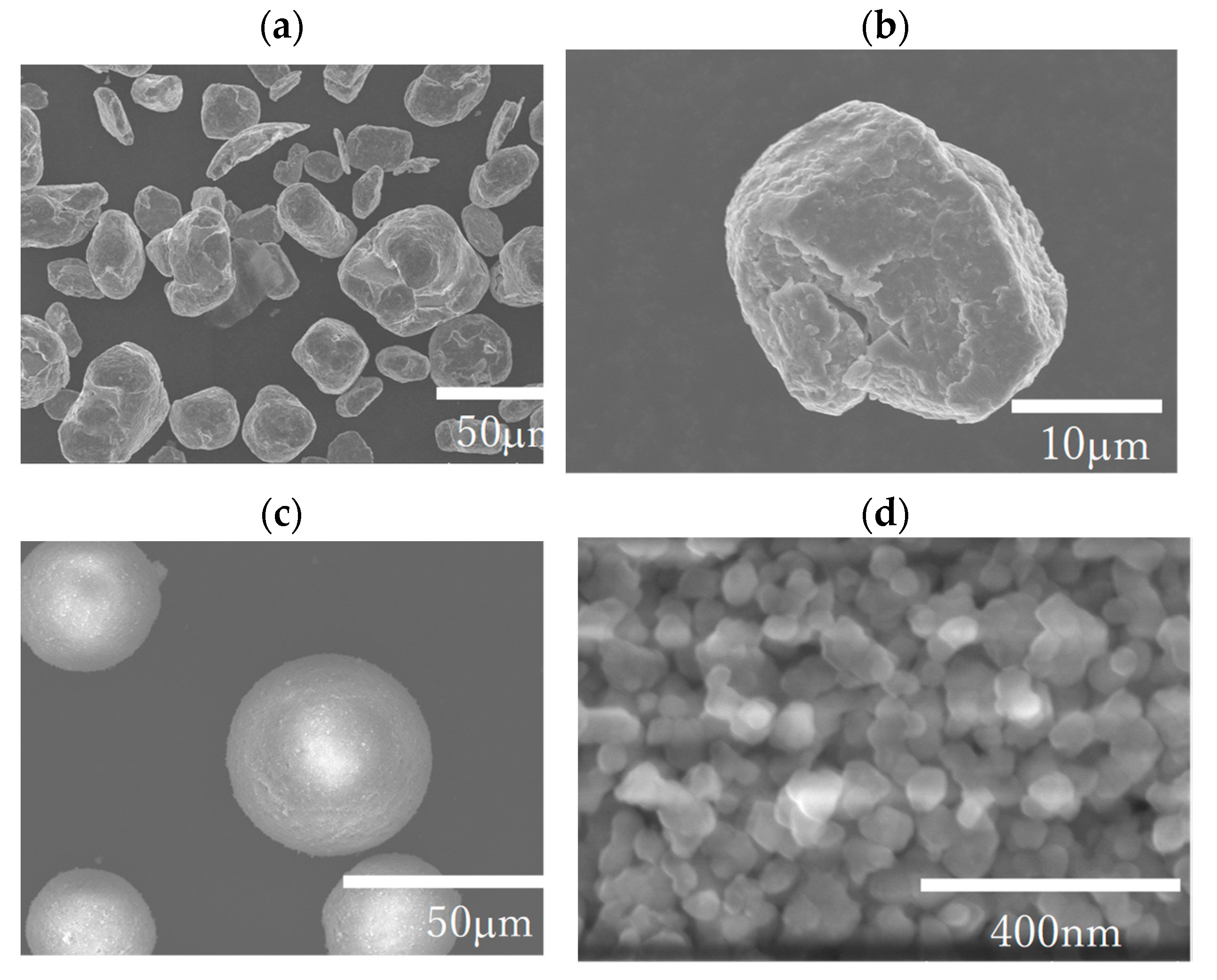
Figure 8.
EDX element mapping results for samples with the rotating speed of 250 rpm for different amounts of PCA dispersant. (a) PCA (0%), (b) PCA (1%), (c) PCA (3%), (d) PCA (5%), (e) PCA (10%), (f) PCA (20%).
Figure 8.
EDX element mapping results for samples with the rotating speed of 250 rpm for different amounts of PCA dispersant. (a) PCA (0%), (b) PCA (1%), (c) PCA (3%), (d) PCA (5%), (e) PCA (10%), (f) PCA (20%).

Figure 9.
Results of element analysis for the samples with rotating speeds of 250 rpm and 1000 rpm with different amounts of dispersant of PCA. (a) for volume fraction (%) of Fe, and (b) for volume fraction (%) of Zr for 250 rpm. (c) for volume fraction (%) of Fe, and (d) for volume fraction (%) of Zr for 1000 rpm.
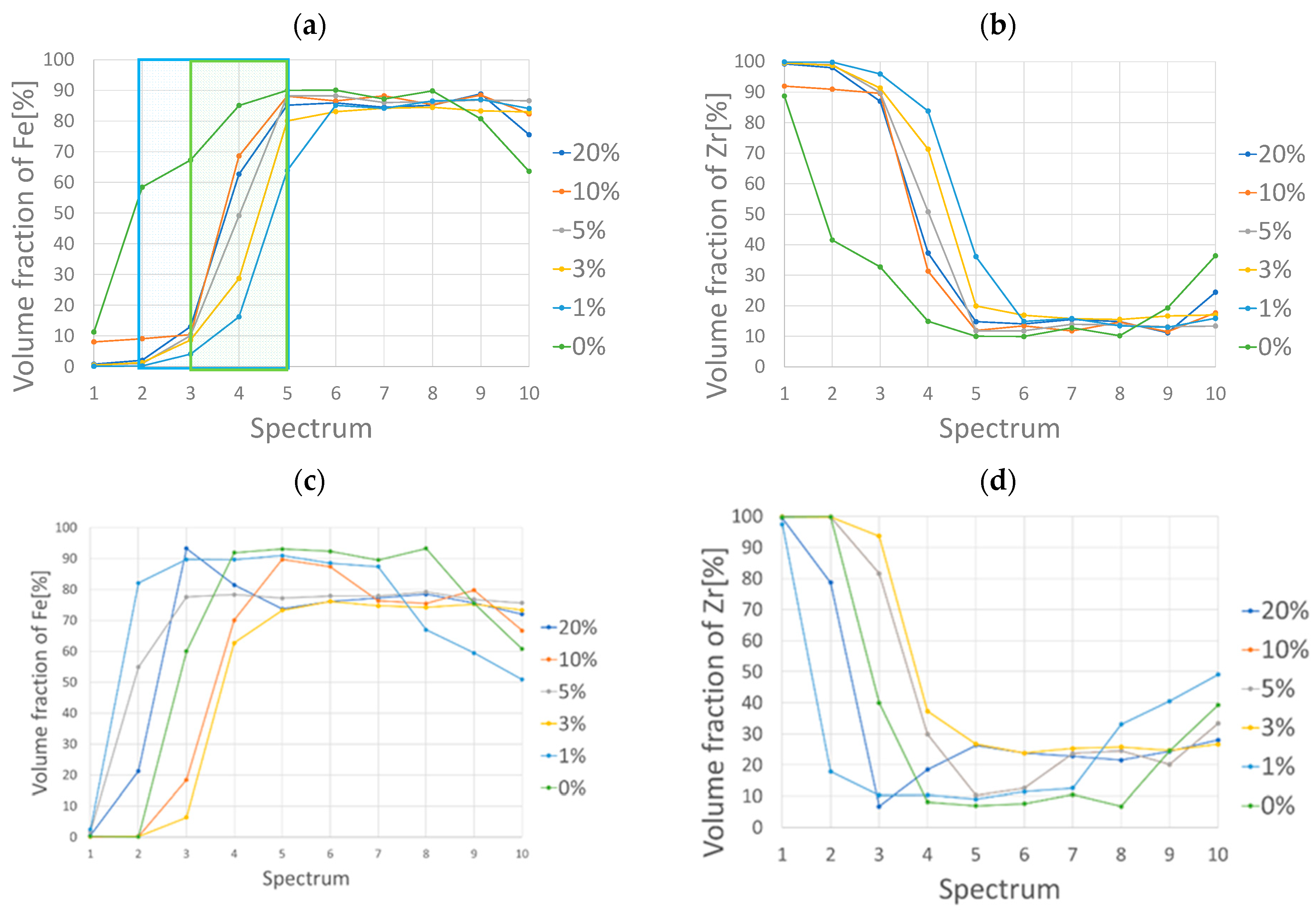
Figure 10.
Compositional gradient distributions for the FGMs with the rotating speed of 250 rpm with fitting curves expressed by Equation (2). The experimental data for PCA from 0 to 20% and fitting curves from n = 0.1 to 4 are shown. The part surrounded by a green line corresponds to the functionally graded layer.
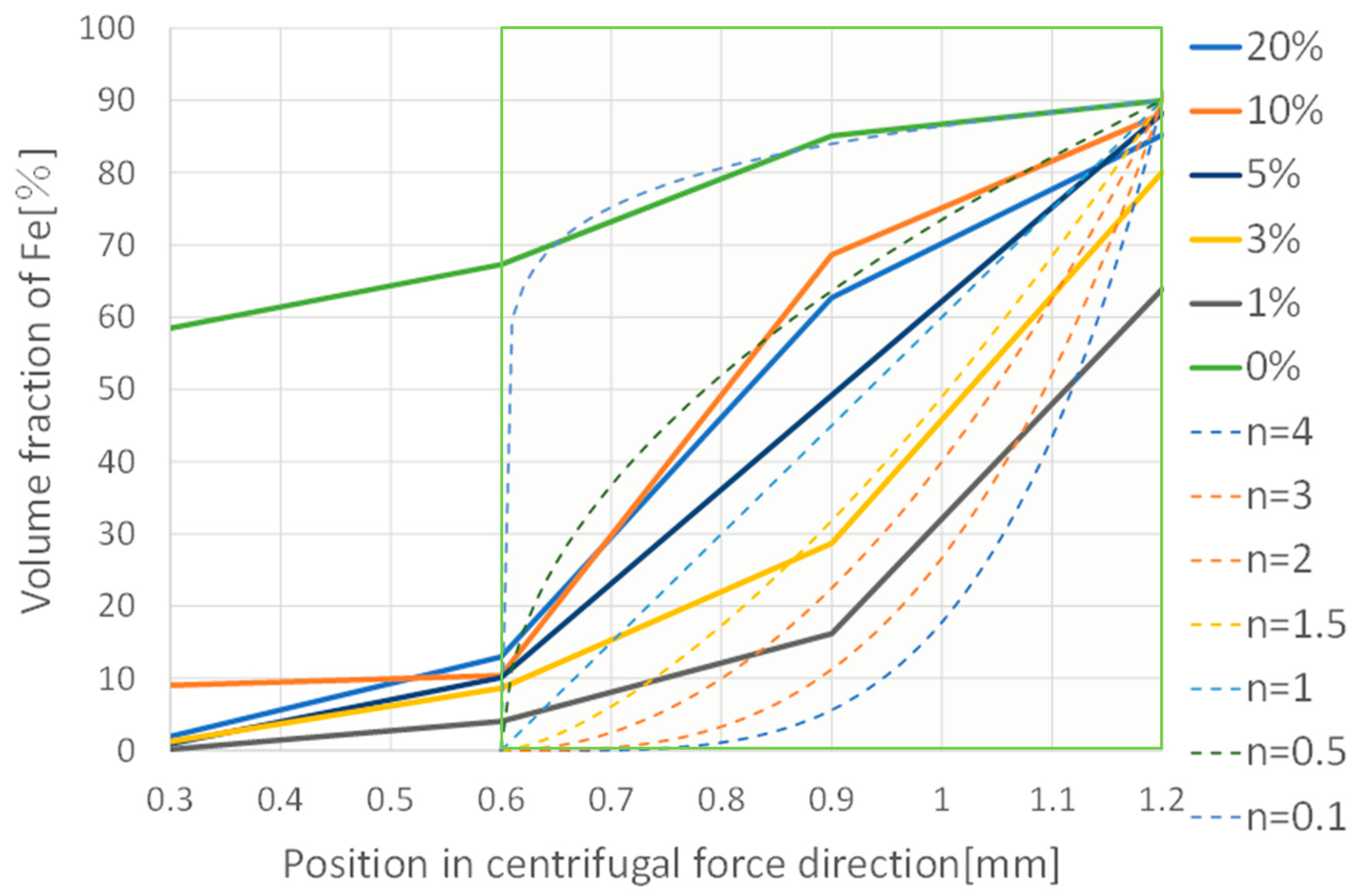
Figure 11.
Optical microscope images of residual indentation impressions for micro Vickers hardness (a) and nanoindentation (b,c). (a) is impression for Micro Vickers hardness, (b) is impression for Nanoindentation (in SUS304 phase), (c) is impression for Nanoindentation (in ZrO2 phase).
Figure 11.
Optical microscope images of residual indentation impressions for micro Vickers hardness (a) and nanoindentation (b,c). (a) is impression for Micro Vickers hardness, (b) is impression for Nanoindentation (in SUS304 phase), (c) is impression for Nanoindentation (in ZrO2 phase).

Figure 12.
Vickers hardness in cross sections in centrifugal force directions in the samples with rotation speeds of 250 rpm (a) and 1000 rpm (b) for a variety of amounts of PCA.
Figure 12.
Vickers hardness in cross sections in centrifugal force directions in the samples with rotation speeds of 250 rpm (a) and 1000 rpm (b) for a variety of amounts of PCA.

Figure 13.
Nanoindentation hardness in cross sections in centrifugal directions in the samples with the rotation speeds of 250 rpm (a) and 1000 rpm (b) for a variety of amounts of PCA.
Figure 13.
Nanoindentation hardness in cross sections in centrifugal directions in the samples with the rotation speeds of 250 rpm (a) and 1000 rpm (b) for a variety of amounts of PCA.
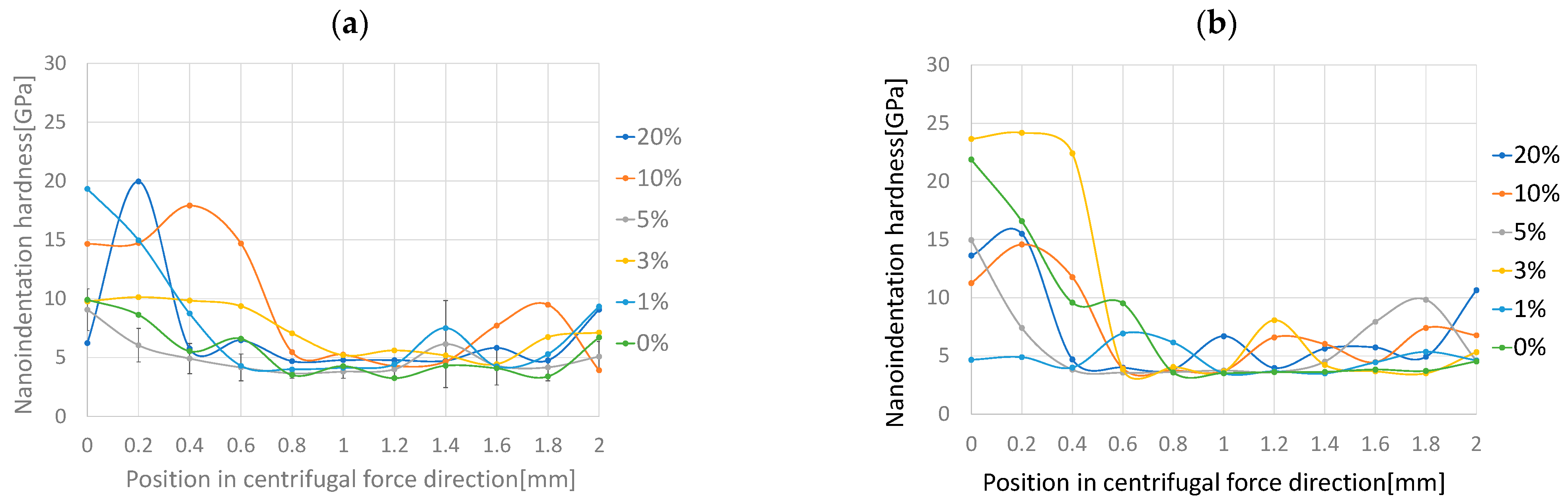
Figure 14.
Crack propagation on ZrO2-rich surfaces in FGMs with the rotating speed of 250 rpm with PCA (0%, 5% and 20%), 5-layered materials and ZrO2 single layer materials under cyclic thermal shock loadings.
Figure 14.
Crack propagation on ZrO2-rich surfaces in FGMs with the rotating speed of 250 rpm with PCA (0%, 5% and 20%), 5-layered materials and ZrO2 single layer materials under cyclic thermal shock loadings.
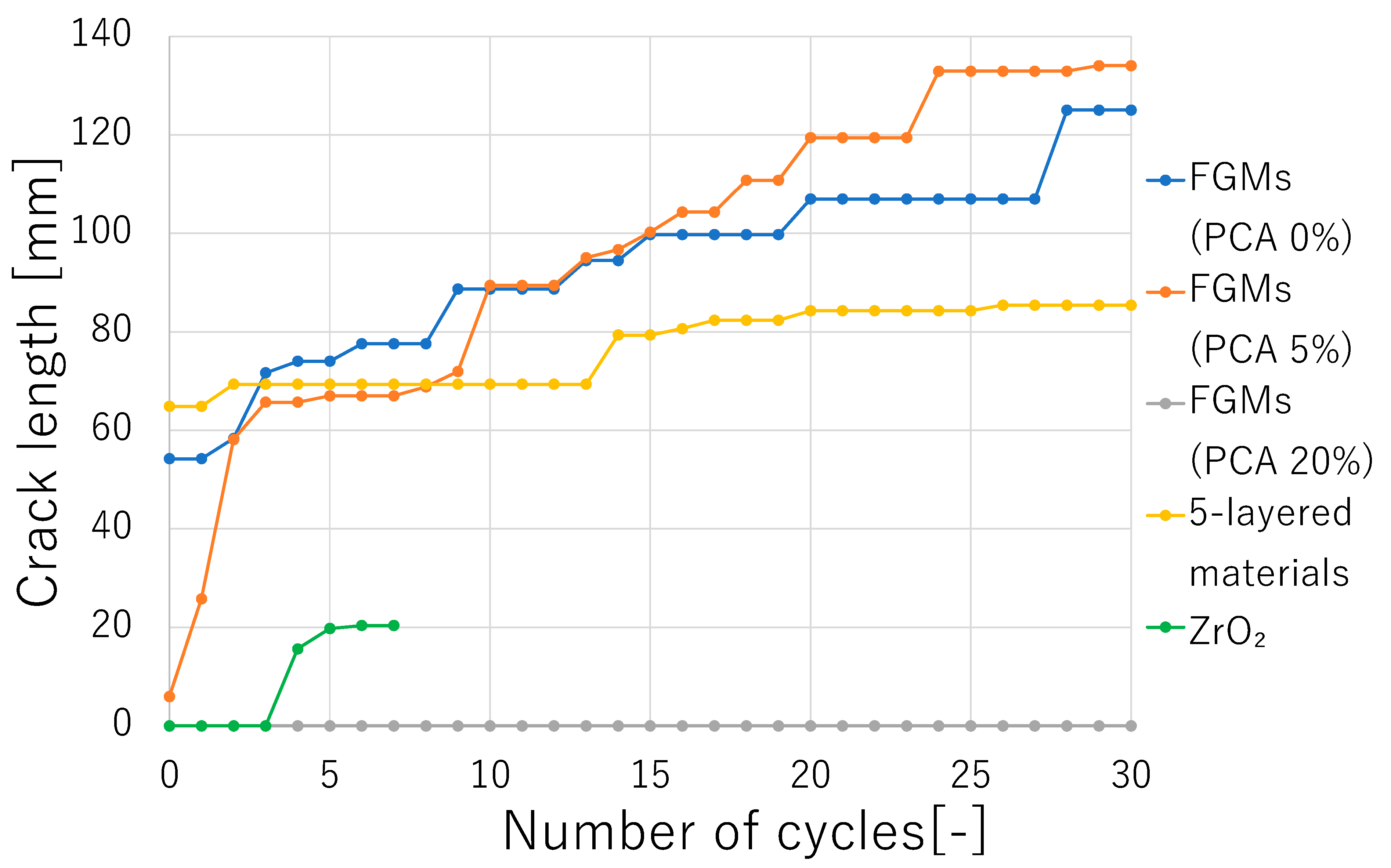
Figure 15.
ZrO2-rich surfaces of the FGMs subject to cyclic thermal shock loadings.
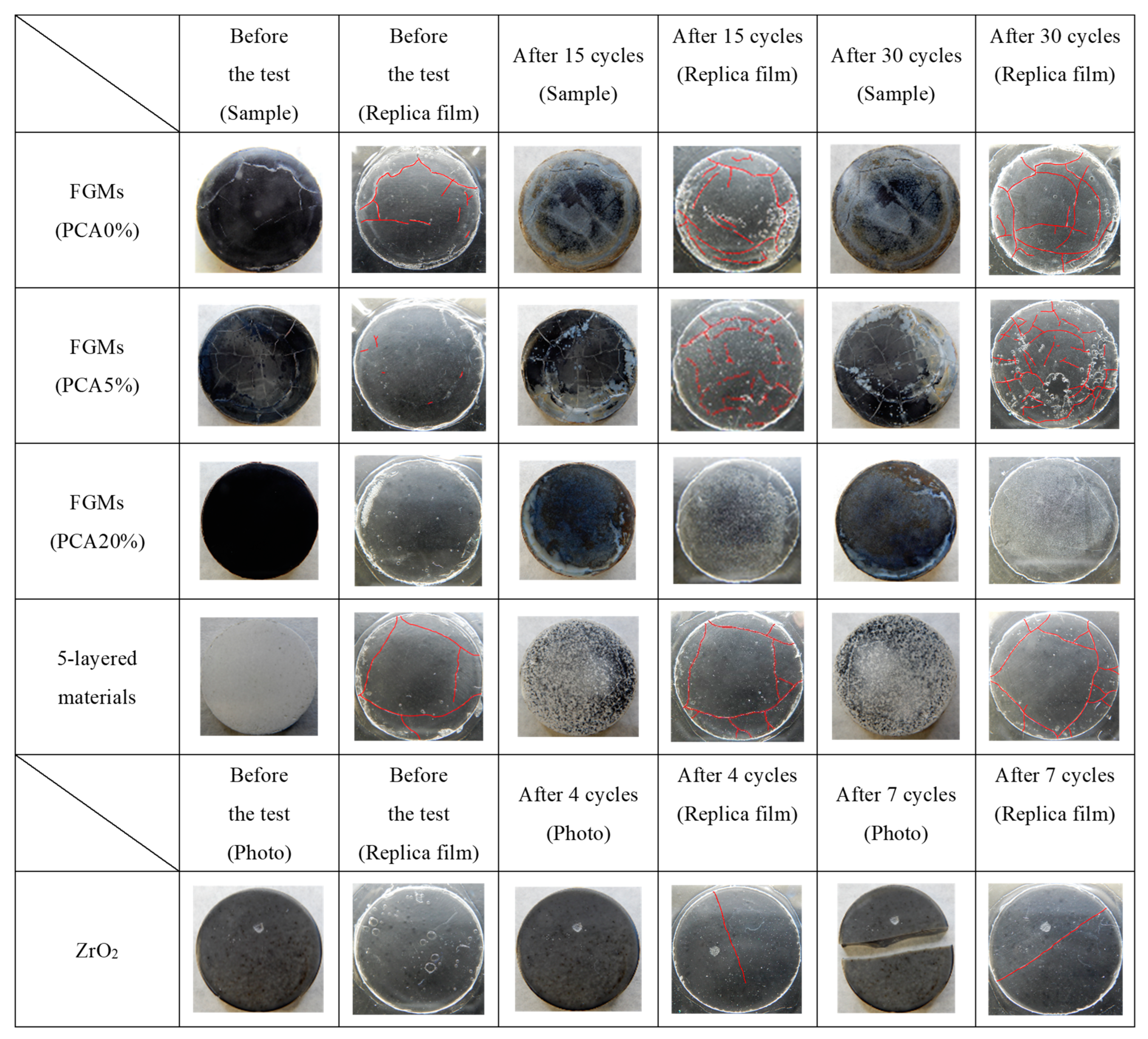
Figure 16.
3-layered (a) and 2-layered (b) samples just after SPS.
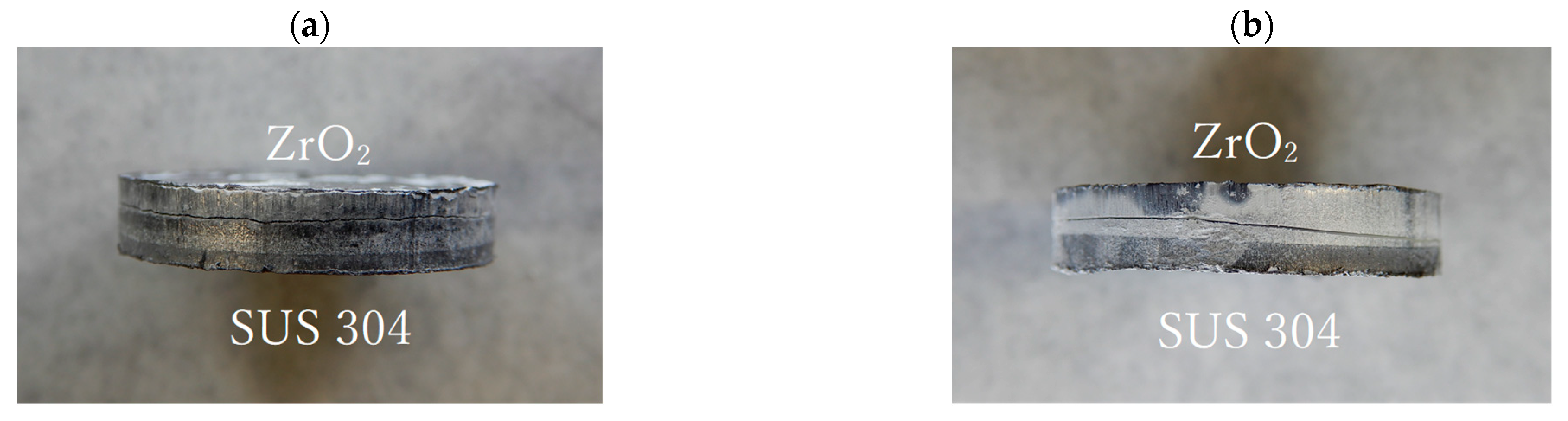
Figure 17.
Vickers hardness on ZrO2-rich surfaces of the FGMs with PCA (0%, 5% and 20%) and 5-layered materials before and after cyclic thermal shock tests.
Figure 17.
Vickers hardness on ZrO2-rich surfaces of the FGMs with PCA (0%, 5% and 20%) and 5-layered materials before and after cyclic thermal shock tests.
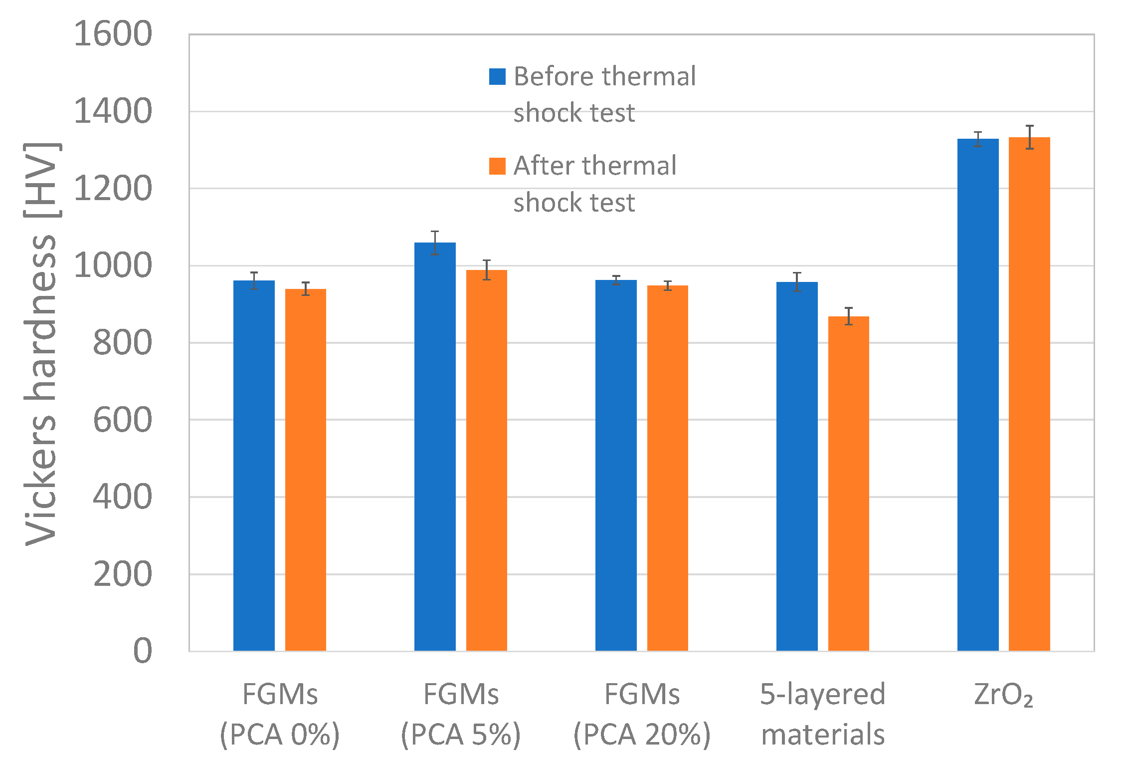
Figure 18.
Vickers hardness indentation impression on ZrO2-rich surfaces of the FGMs with PCA (20%) before (a) and after (b) cyclic thermal shock tests.
Figure 18.
Vickers hardness indentation impression on ZrO2-rich surfaces of the FGMs with PCA (20%) before (a) and after (b) cyclic thermal shock tests.

Figure 19.
Fracture toughness of the samples of FGMs with PCA (0%, 5% and 20%), 5-layered materials and ZrO2 single-layer materials after cyclic thermal shock tests.
Figure 19.
Fracture toughness of the samples of FGMs with PCA (0%, 5% and 20%), 5-layered materials and ZrO2 single-layer materials after cyclic thermal shock tests.
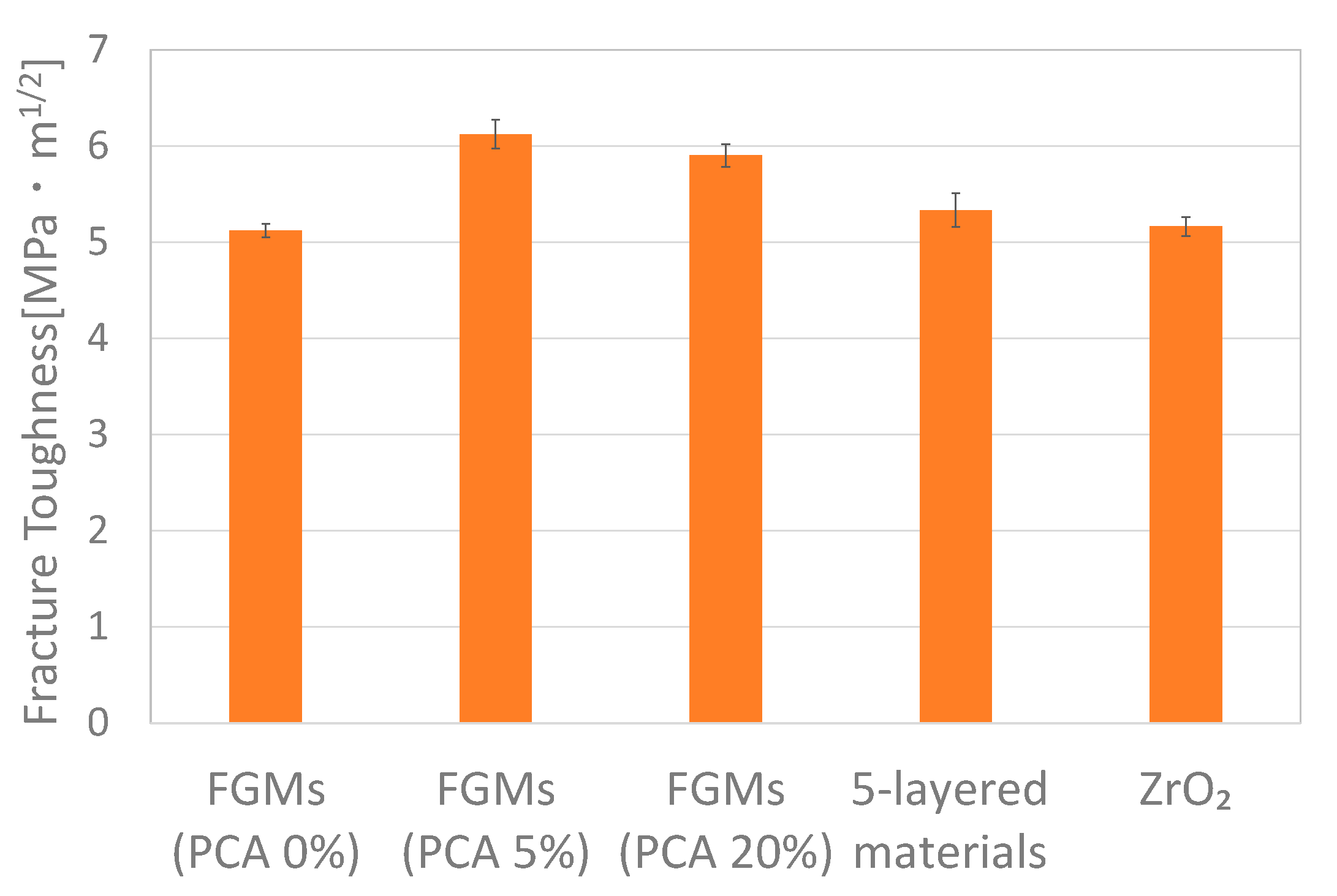
Figure 20.
Simulated sedimentation velocity, (a) for SUS304, and (b) for ZrO2 (particles and aggregations).
Figure 20.
Simulated sedimentation velocity, (a) for SUS304, and (b) for ZrO2 (particles and aggregations).


Table 1.
Conditions for Micro Vickers hardness test and nanoindentation test.
| Measuring Method | Load [mN] | Approaching Time [s] | Loading Time [s] | Unloading Time [s] |
|---|---|---|---|---|
| Micro Vickers hardness test | 4903 | 4 | 10 | 4 |
| Nanoindentation test | 30 | 30 | 10 | 30 |
Table 2.
Density and particle size of SUS304 and ZrO2.
| Density | Particle Size | |
|---|---|---|
| SUS304 | 7930 [kg/m3] | 40 [µm] |
| ZrO2 | 6050 [kg/m3] | 62 [nm] for a particle, 30 [µm] for an aggregation |
Table 3.
Density and viscosity of solvent and dispersant.
| Density | Viscosity | |
|---|---|---|
| Distilled water | 789 [kg/m3] | 0.89 [mPa·s] |
| PCA | 1084 [kg/m3] | 98 [mPa·s] |
Disclaimer/Publisher’s Note: The statements, opinions and data contained in all publications are solely those of the individual author(s) and contributor(s) and not of MDPI and/or the editor(s). MDPI and/or the editor(s) disclaim responsibility for any injury to people or property resulting from any ideas, methods, instructions or products referred to in the content. |
© 2023 by the author. Licensee MDPI, Basel, Switzerland. This article is an open access article distributed under the terms and conditions of the Creative Commons Attribution (CC BY) license (https://creativecommons.org/licenses/by/4.0/).
Share and Cite
MDPI and ACS Style
Tsukamoto, H. Cyclic Thermal Shock Response of Zirconia/304 Stainless Steel Functionally Graded Materials Fabricated by Centrifugal Slurry Methods. J. Compos. Sci. 2023, 7, 69. https://doi.org/10.3390/jcs7020069
AMA Style
Tsukamoto H. Cyclic Thermal Shock Response of Zirconia/304 Stainless Steel Functionally Graded Materials Fabricated by Centrifugal Slurry Methods. Journal of Composites Science. 2023; 7(2):69. https://doi.org/10.3390/jcs7020069
Chicago/Turabian StyleTsukamoto, Hideaki. 2023. "Cyclic Thermal Shock Response of Zirconia/304 Stainless Steel Functionally Graded Materials Fabricated by Centrifugal Slurry Methods" Journal of Composites Science 7, no. 2: 69. https://doi.org/10.3390/jcs7020069