Article

Nonlinear Finite Element Analysis of Tubular Steel Wind Turbine Towers near Man Door and Ventilation Openings to Optimize Design against Buckling

by
Charis J. Gantes
1,*,
Stelios M. Vernardos
1,
Konstantina G. Koulatsou
1 and
Semih Gül
2
1
Institute of Steel Structures, National and Technical University of Athens, GR-15772 Athens, Greece
2
Ateş Wind Power, 35720 Izmir, Turkey
*
Author to whom correspondence should be addressed.
Vibration 2024, 7(1), 212-228; https://doi.org/10.3390/vibration7010012
Submission received: 30 January 2024 / Revised: 3 March 2024 / Accepted: 5 March 2024 / Published: 7 March 2024
(This article belongs to the Special Issue Analysis and Design of Wind Turbine Towers)

Abstract

:
The safe and cost-effective design of wind turbine towers is a critical and challenging aspect of the future development of the wind energy sector. This process should consider the continuous growth of towers in height and blades in length. Among potential failure modes of tubular steel towers, shell local buckling due to static axial compressive stresses from the rotor, blades, and tower weight, as well as dynamic flexural compressive stresses from wind actions on the rotating blades and the tower itself, are dominant as thickness is optimized to reduce weight. As man door and ventilation openings are necessary for the towers’ operation, the local weakening of the tower shell in those areas leads to increased buckling danger. This is compensated for by tower manufacturers by the provision of stiffening frames around the openings. However, the cold-forming and welding of these frames are among the most time-consuming aspects of tower fabrication. Working towards the optimization of this design aspect, the buckling response of tubular steel towers near such openings is investigated by means of nonlinear finite element analysis, accounting for geometrical and material nonlinearity and imperfections (GMNIA), and also considering several wind directions with respect to the openings. The alternatives of stiffened and unstiffened openings are investigated, revealing that a thicker shell section around the opening may be sufficient to restore lost stiffness and strength, while the stiffener frame may also be eliminated, offering substantial benefits in terms of manufacturing effort, time and cost.

1. Introduction

In order to achieve continuously increasing percentages of energy production from renewable sources [1,2,3] to meet the ambitious targets set by countries and international organizations, the design of towers is receiving great attention as they are an inherent part of wind turbines.
The most common type of wind turbine tower used nowadays for both on-shore and off-shore applications is the free-standing tubular steel tower. Such towers consist of individual tubular sections, each comprising one or more cylindrical cans, fabricated by the roller bending of flat plates and subsequent longitudinal welding along their common meridional edges. Adjacent cans are then held in place next to each other and welded together along their common circumferential edges. Multiple cans are thus joined to produce a tubular section, with such length as to fit in a track for transportation from the factory to the wind farm site. In the factory, tubular sections are fitted at their ends with ring flanges featuring predrilled bolt holes. During erection on the wind farm site, the continuity between adjacent tubular sections is ensured by means of pretensioned bolted connections between their ring flanges.
The bottom part of the tower comprises a manhole opening to accommodate access to the interior of the tower and to the staircase and elevator leading to the tower top, allowing for the maintenance of electrical and mechanical parts (Figure 1). Moreover, in modern towers with heights exceeding 100 m, ventilation openings are also inserted at different heights to ensure healthy conditions for personnel working in the tower (Figure 2). Openings of both types weaken the tower shell, inducing stiffness reduction, causing stress concentrations, and increasing danger of local buckling. This is addressed by different measures, most commonly by welding a peripheral frame around the opening, as seen in the photos of Figure 1 and Figure 2. However, the cold-forming and welding of stiffening frames around the openings are among the most time-consuming and costly aspects of tower fabrication. The fabrication of frames is commonly subcontracted by tower manufacturers, and then substantial effort and time are required for welding the frames onto the tower, as well as for carrying out necessary non-destructive testing. Moreover, these welded connections are susceptible to fatigue due to cycles of wind-induced stress concentrations. For these reasons, tower designers are exploring alternative solutions without stiffening frames, and research efforts are ongoing to evaluate such alternatives, both numerically and experimentally.
The main structural actions on wind turbine towers comprise axial compression due to the weight of the tower and the weights of the rotor and blades imposed at its top, as well as flexure due to the interaction with wind, causing pressure on the tower and on the rotating blades. The necessary structural verifications include avoiding resonance between the tower and the rotating blades, preventing the local buckling of the tower shell, and performing fatigue checks at the welded and bolted connections [4]. The thickness of the tower cans is mostly dictated by buckling checks.
The structural design of wind turbine towers is commonly carried out by the engineering departments of wind turbine companies according to international guidelines [5,6,7,8]. In Europe, the design of wind turbine towers against buckling is performed according to Parts 1–6 of Eurocode 3 [9,10]. Buckling checks are performed at the section level, taking the dynamic nature of the tower’s response to wind indirectly into account. Namely, action effects are obtained from specialized software, such as [11], where the dynamic aeroelastic interaction between tower, blades, and wind, as well as the control system of the turbine, is taken into consideration. The wind field is modeled as a stochastic process and 10 min wind time histories are artificially generated. These are used as inputs for computing the time histories of action effects over the tower height [12]. Such analyses are repeated for a large number of wind time histories corresponding to the entire spectrum of mean wind velocities within the operating range of the turbine, so that the results are statistically significant.
In these aeroelastic, dynamic simulations, the tower is modeled simplistically, with a relatively coarse beam element mesh. Such a model is sufficient for providing time histories of action effects over the tower height but is not capable of performing local buckling verifications. On the other hand, advanced finite element software, which is capable of nonlinear analyses of shell element models of the tower to detect local buckling (for example [13]), cannot take into account aeroelastic interaction and control. For that reason, despite the dynamic nature of the phenomenon, buckling verifications of wind turbine towers are performed against equivalent static action effects, which are computed at the different sections of a tower’s height as the maximum values of all corresponding time histories obtained from the aeroelastic simulations. In most cases this equivalent static verification is performed analytically, on the basis of code provisions [9,10]. In areas of discontinuities, such as the considered openings, analytical formulas are not available in codes or in the literature, and nonlinear finite element analyses are necessary (for example [14]). Considering the very dense finite element mesh that is needed for reliable shell buckling prediction, these analyses are static. Some dynamic analyses have been attempted for research purposes (for example [15]), but they are less reliable due to the necessity for coarser mesh and are still prohibitive from a computational effort point of view for use in everyday engineering design applications.
Due to its numerous applications in many engineering fields, shell buckling has been studied extensively for many years. The buckling of cylindrical shells was studied experimentally for the case of axial compression in elastic [16,17,18] and inelastic regions [19,20,21], exhibiting significant deviations from analytical solutions, due to the strong influence of imperfections on the buckling response of thin shells. Buckling tests of cylinders in bending were also performed by several researchers [22,23,24,25], yielding similar conclusions.
Wind turbine towers differ from most cylindrical and conical shells that have been studied in the literature in one important aspect, namely, they exhibit a stepwise variation in shell thickness owing to their fabrication process. As each can is fabricated from a different plate, the shell thickness is different from one can to the next, the aim being to optimize the overall tower weight. The lack of analytical solutions for the buckling of shells with stepwise varying thickness is treated in Part 1–6 of Eurocode 3 [9,10] by transforming the actual tower geometry into approximately equivalent sections of uniform thickness between the tower’s ring flanges. Moreover, the tower is subjected to combined axial and flexural actions, with both contributing significantly to the resulting stress state. Torsion is also not negligible, particularly towards the top of the tower, producing shear stresses that must be accounted for in buckling verifications. In addition, the shell thickness is relatively high towards the tower’s base and smaller near the top, resulting in varying local slenderness relative to height.
Due to the above reasons, a numerical treatment of the tower’s buckling response is pertinent. The buckling behavior of wind turbine towers was investigated by some of the authors in [26,27], placing emphasis on the numerical modeling of the ring flanges away from the openings, while a very comprehensive investigation was published recently [28,29].
The research papers reported in [30,31,32,33,34,35] are typical experimental studies of axially compressed shells with openings, while for shells with openings under bending experimental work has been carried out in [36,37]. It is noted, however, that these tests refer to geometries and slenderness ranges that are different from those near the base of wind turbine towers, where man door and ventilation openings are commonly located. The effect of stiffened cutouts on the buckling response of cylindrical steel shells with geometric characteristics, which are typical of modern wind turbine towers, has been studied by a group of the primary author experimentally and numerically [38,39], focusing on the comparison between alternative stiffener configurations. The issue has also been addressed in the last decade by other investigators [40,41].
Recently, the problem has been revisited, focusing on addressing the desire of tower fabricators to eliminate the stiffening frame in order to improve the speed, cost and non-destructive testing requirements of the manufacturing process. Hence, unstiffened openings are investigated, where the stiffness and strength reduction caused by the opening are addressed by increased plate thickness. Some initial efforts to compare stiffened and unstiffened man door openings were attempted in [42], while a preliminary version of the present paper, also involving ventilation openings, was presented by the authors in [43].
In the present paper, the buckling response of tubular wind turbine towers under realistic wind loads is systematically investigated, with a focus on the behavior near the man door and ventilation openings. Serving the research need described above, particular attention is directed towards avoiding the stiffening frame and instead using thicker plates around the openings. This may lead to heavier solutions; however, it helps to reduce substantially the necessary cutting, forming, and welding work during tower fabrication. The effect of plate thickness is discussed along these lines. The investigation is carried out by employing nonlinear finite element analyses, accounting for geometrical and material nonlinearity and imperfections (GMNIA) [44,45].

2. Materials and Methods

For the purposes of the present investigation, a wind turbine is considered with a tubular tower of approximately 120 m in height and a diameter of 4.3 m over the lower sections containing the openings. Typical man door and ventilation opening dimensions, as well as loads acting on the tower, are considered.

2.1. Geometry

The width and height of the considered man door and ventilation openings are summarized in Table 1. Moreover, the detailed geometry of the openings is illustrated in Figure 3 (man door opening) and Figure 4 (ventilation opening). The dimensions, plate thicknesses, and stiffening schemes shown in these figures are adopted from actual tower designs. It is noted that man door openings are much larger than ventilation openings; accordingly, the disruption of stress flow around the man door openings is expected to be much more intense.

2.2. Modeling Details

Different finite element models were developed using the general-purpose finite element software ADINA [17]. These comprised different configurations of the tower with stiffened and unstiffened man door and ventilation openings. Shell finite elements were used to model the towers, while the ring flanges and the stiffening frames around the opening could be modeled with either shell elements or beam elements representing the sections of both flanges assumed to act together, thus taking into account the geometrical eccentricity between the flange axis and shell mid-surface by means of rigid elements, adopting the findings regarding numerical modeling reported in [27]. In the present paper, the modeling of flanges and stiffeners with shells was adopted for increased accuracy. As the objective was to assess the buckling potential of the tower in the areas of the aforementioned openings, and in order to reduce the computational demands, instead of modeling the entire tower, only sufficiently long parts of the tower around the examined openings were included in the models.
Appropriate boundary conditions are applied at the models’ ends, which are properly selected to correspond to ring flange positions. Namely, the lower shell part is fixed at its base, while the upper part is free at its top, corresponding to a ring flange connection. As the ring flange stiffness is sufficient to guarantee the undeformability of the top section in its plane, all shell nodes at the top of the model are linked via a rigid constraint to a master node at the geometric center of the cross-section to facilitate load application.
The mesh density was decided following a sensitivity analysis, with gradual mesh refinement until further refinement resulted in no essential differences with respect to initial stiffness, ultimate load, and overall behavior. The different finite element models comprised a total number of approximately 20,000 shell elements of varying size, ranging from 40 to 90 mm.

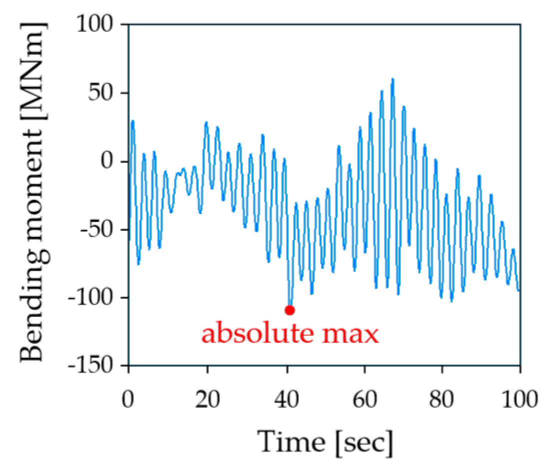
2.3. Loading Details

As mentioned above, action effects (axial and shear forces, and bending and torsional moments) at specified cross-sections over the tower height are assessed by means of dynamic aeroelastic analyses performed with specialized software, such as [11]. The tower is modelled with beam elements and the wind turbine system is subjected to randomly generated wind velocity time histories, commonly 100 s in duration. A typical bending moment time history at a cross-section near the tower base is illustrated in Figure 5. The maximum absolute value of each action effect is extracted from each time history along with the simultaneous values of the other action effects.
Similar analyses are performed for several artificially generated wind time histories corresponding to the entire spectrum of mean wind velocities within the operating range of the turbine. The maximum values of all action effects are recorded from all these analyses and are used as equivalent static actions for the buckling verification of the tower at regularly spaced cross-sections over its height. Diagrams of maximum absolute values of axial force, shear force, and bending moment at 10 m intervals are shown in Figure 6.
For the purposes of the present investigation, it was assumed that the examined opening is near the tower base and that the vertical distance between the tower top and the flange above the man door opening is 110 m. As mentioned above, all shell nodes at the top of the model were linked via a rigid constraint to a master node at the geometric center of the cross-section, where loads were applied in a quasi-static fashion. A pushover-type nonlinear static analysis was carried out, as described in the next section. Three action effects were applied, namely, a vertical force representing the weight of the rotor, nacelle, blades and upper tower sections, a horizontal force representing the wind action on the rotor, and a bending moment, causing flexure about the same axis as the flexure due to the horizontal force. The ratio of vertical to horizontal force was considered equal to 6.5 based on available data taken from actual towers and in accordance with Figure 6. The bending moment was taken to be equal to the horizontal force multiplied by the vertical distance of 110 m, which was also in accordance with Figure 6. The amplitude of loading was chosen to correspond to a buckling strength safety factor of approximately 1.5 in the tower without any opening.
The other three action effects that are present in actual towers, namely, horizontal force and bending moment in the crosswind direction, and torsional moment due to eccentricities, are much smaller and have, therefore, not been taken into account in this comparative investigation.

2.4. Analysis Details

The design methodology presented in [44] is employed. This is based on nonlinear finite element analyses and uses general-purpose finite element software ADINA [17]. Linearized buckling analyses (LBA) are initially carried out in order to obtain the upper limits of strength and, mainly, buckling modes, which are then used as shapes of initial imperfections for the subsequent nonlinear analyses [46].
Next, nonlinear finite analysis, considering geometrical and material nonlinearity and initial imperfections (GMNIA), is performed. The results are presented in terms of equilibrium paths, in which the load amplification factor is plotted on the vertical axis and a characteristic deformation quantity is plotted on the horizontal axis. The initial stiffness and ultimate strength in the equilibrium path are representative quantities of the structural response and are used to compare the considered alternative stiffening approaches of the tower shell around the opening.
The so-called collapse method [47], which is an arc-length type of solution algorithm, is adopted to obtain the non-linear equilibrium path of the model, enabling us to also trace the descending branch. The “angle” between the ascending and descending branch of the equilibrium path, and the associated area between the equilibrium path and the horizontal axis, provides insight into the levels of ductility offered by each stiffening solution.
Viewing deformations and stress distributions at characteristic points along the equilibrium path, particularly on its descending branch, helps to identify the weakest areas of the structural configuration, where buckles and stress concentrations are encountered. This is in turn useful for proposing targeted strengthening measures.

3. Results

Different arrangements of the presented openings are considered, comprising sections with a single man door opening, two ventilation openings at the same level, as well as a man door opening and a ventilation opening at the same level. The results are presented next.

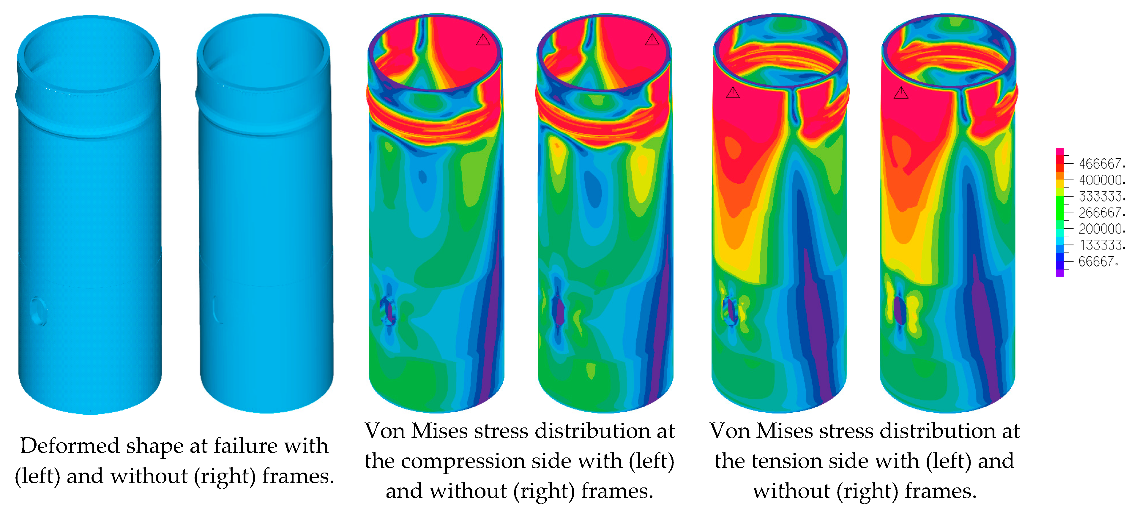
3.1. Section with Man Door Opening

A section with a man door opening with the geometry shown in Figure 3 was modeled and analyzed. Four alternative arrangements of strengthening around the man door opening were considered, denoted as cases 3 to 6, and were compared to case 1, which was the section without any opening, and to case 2, which was the section with an opening without any strengthening. The four strengthening cases are described next:
  • Case 3: with a 65 mm thick door plate around the man door opening and with a stiffening frame like that illustrated in Figure 3;
  • Case 4: without thickening of the door plate around the man door opening but with a stiffening frame, the same as the one illustrated in Figure 3;
  • Case 5: with 65 mm thick door plate around the man door opening, but without a stiffening frame;
  • Case 6: with 75 mm thick door plate around the man door opening, but without a stiffening frame.
The more onerous loading direction, causing maximum compression on the side with the man door opening, was considered. GMNI analyses of the six cases were performed and the resulting equilibrium paths are presented in Figure 7, where the load multiplier λ of the design loads is plotted on the vertical axis, and the lateral displacement at the top of the modelled tower section is plotted on the horizontal axis.
When comparing cases 1 and 2, it is obvious that the man door opening causes significant stiffness and strength reduction. From the deformations at failure of these two cases, shown in Figure 8, it is observed that in case 2 local buckling takes place much lower, occurring at the level of the opening, where sectional weakening results in stress concentrations. It is hence clear that the stiffening of the section around the opening is necessary to recover the lost strength and stiffness.
The basic stiffening design of case 3, comprising both thickening of the door plate and a peripheral stiffening frame, is fully effective in recovering from the loss of stiffness and strength, exhibiting an equilibrium path that is almost identical to that in case 1. Moreover, from the deformation in Figure 8, it is observed that the buckle in case 3 occurs at almost the same location as in case 1. In case 4, with a stiffener frame but without a thicker door plate, the stiffness reduction is initiated at lower loads, but a slightly higher strength is achieved, and the degradation beyond the ultimate load is less sharp, indicating higher ductility. Buckling occurs at the top of the man door opening and seems to be arrested by the frame.
The response of case 5, with a 65 mm thick door plate but without stiffener frame, is similar to that in case 4, but the stiffness reduction starts at a lower load level, and the ultimate strength is also lower. Buckling occurs near the mid-height of the opening. As mentioned above, the elimination of the stiffener frame is desirable from the fabrication point of view as there is no need for the separate procurement of stiffener frames and because the associated welding effort is much less. Thus, the further thickening of the door plate is investigated in case 6, where, for a 75 mm thick door plate, buckling occurs also near the mid-height of the opening, but at higher load levels due to the thickening, so that the loss in strength is almost fully compensated.
Regarding the initial stiffness, which is important in terms of the tower resonance verification, it is observed that all stiffening cases from 3 to 6 exhibit almost the same stiffness as case 1 for load levels up to approximately λ = 1; hence, they are equally effective from that point of view.
The von Mises stress distributions at failure for cases 3, 4 and 5 are presented in Figure 9. Stress concentrations, denoted with a red color, are encountered at the same locations where the buckles and wrinkles occur in the deformed shapes of Figure 8. If both a thick door plate and peripheral stiffener are used, failure occurs well above the opening. If only peripheral stiffener is employed, failure is observed near the top of the opening. If only thick door plate is adopted, failure is in the middle-upper part of the opening. In both cases 4 and 5, the high-stress area is more extended. The behavior in case 6 is qualitatively similar to that in case 5.

3.2. Section with Two Ventilation Openings

Next, the response of a section with two ventilation openings, which had the geometry illustrated in Figure 4 and were arranged at the two opposite ends of a section diameter, was investigated. Typical wind turbine tower designs feature stiffening frames around such ventilation openings. Numerical modeling and GMNI analyses have been conducted, subjecting the section to the same loads as used for the man door openings and applying them at the top. Considering the symmetry of this tower section, three different angles of loading application within a quarter-circle were examined, as shown in Figure 10.
In Figure 11, load–displacement curves for the three considered wind directions are presented. It is observed that the ultimate load is almost identical for all wind angles. However, significantly less ductility is achieved for the 45° and 90° angles compared to the 0° angle. This is attributed to the fact that the two ventilation openings for the 0° angle are on the neutral axis. The 90° angle is selected for use in further investigations.
To assess the benefit of using stiffening frames around the ventilation openings, the tower section’s response with and without such frames is compared. The obtained load–displacement curves are shown in Figure 12, and the corresponding deformed shapes and von Mises stress distributions at failure are seen in Figure 13. Failure takes place due to local buckling near the top of the tower section, regardless of the presence of a frame. Material yielding is concentrated at the buckles on the compression side, while on the tension side the stress distribution is smoother and high stresses extend over a larger area. The frames’ presence does not seem to have any substantial beneficial effect on the response, which could have been anticipated considering the openings’ small size.
Having concluded that it is possible to omit the stiffening frames around the ventilation openings without seeing any adverse effect on the structural response, the influence of the plate thickness of the part hosting the openings is also investigated. Three shell thickness values are compared, namely, 44 mm, 48 mm, and 58 mm. The obtained load–displacement curves are shown in Figure 14 and the corresponding deformed shapes and von Mises stress distributions at failure are seen in Figure 15. It can be observed that for the two smaller thickness values buckling occurs at the openings and a more ductile behavior is achieved characterized by a smooth post-buckling path. With a higher examined thickness, buckling moves towards the top and a more abrupt post-buckling path is obtained. With respect to ultimate load, the two higher thickness values yield comparable results, while the thinner shell has a smaller ultimate strength. Thus, the intermediate thickness value of 48 mm combines the benefits of material savings, high ductility, and high stiffness and strength.

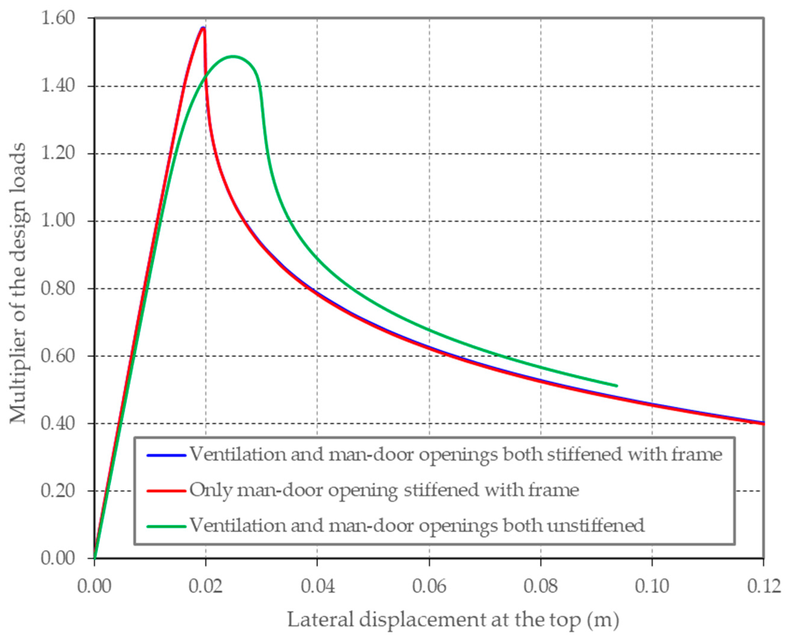
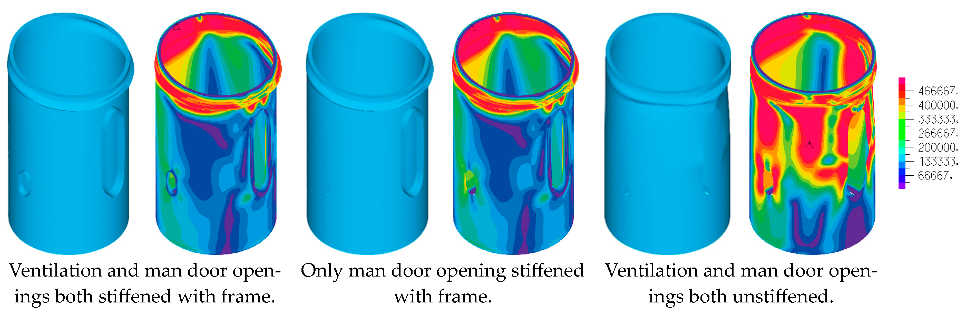
3.3. Section with Man Door and Ventilation Opening

Finally, the case of both a man door opening and a ventilation opening located at 90° angles in the lower part of the examined tower section was investigated. The same loads were used as for the previously studied cases. Two load cases were considered, one using loads aiming to cause maximum compression at the man door and the other at the ventilation opening.
For loads directed at the man door opening, the obtained load–displacement curves are presented in Figure 16 and the corresponding deformed shapes and von Mises stress distributions at failure are seen in Figure 17. The effect of using stiffening frames around the openings can be assessed from these figures. The ventilation opening frame appears to have no significant effect on the behavior of the section, while the man door frame seems to limit yielding to the upper area. The absence of it results in more extensive yielding but enhances ductility. This behavior was expected when taking into account the size difference of the two openings discussed in Section 2.1.
When the loads are directed towards the ventilation opening, neither the ventilation opening frame nor the man door opening frame appear to have any effect on the behavior of the section. This is attributed to the fact that in this case the man door opening is located at the neutral axis of the cross-section, while the ventilation opening is too small to have any noticeable effect. The obtained load–displacement curves are presented in Figure 18, and the corresponding deformed shapes and von Mises stress distributions at failure are shown in Figure 19.

4. Discussion

The objective of the presented investigation was to evaluate alternative strengthening measures around man doors and ventilation openings in tubular steel wind turbine towers. The aim of strengthening is to recover the loss in stiffness and strength due to such openings, which are necessary for operational reasons of the wind turbine. It is common practice in the tower industry to employ peripheral stiffening frames around the openings. These are sometimes combined with thicker shell plates in this area. This investigation was motivated by the heavy demands in terms of labor and cost for the fabrication and installation of stiffening frames.
A numerical approach was employed for the investigation. This was based on performing Geometrically and Material Nonlinear Analyses with Imperfections (GMNIA) of a detailed finite element model of the tower section containing the openings, which was subjected to a realistic combination of axial and flexural loading corresponding to that of a 120 m tubular steel tower. The analyses results were presented and evaluated by means of load–displacement curves accompanied by snapshots of deformation and stress distribution at failure.
For the ventilation openings, featuring relatively small size, it has been concluded that the stiffening frame is unnecessary as it makes a negligible contribution to the initial stiffness and ultimate strength. The thickness of the shell plate around the opening has a more pronounced effect. High plate thickness is beneficial for stiffness and strength, but leads to a more abruptly declining post-buckling response. Average plate thickness is preferable to achieve balanced stiffness, strength, and ductility characteristics.
For the man door openings with significantly larger sizes, both the stiffening frame and the shell plate thickness make a significant contribution to the initial stiffness and ultimate strength. The combination of stiffening frame and thicker shell plate employed in the current designs leads to a response closely resembling the case of a tower without any opening. On the other hand, eliminating the frame and appropriately increasing the plate thickness results in comparable stiffness and strength, as well as improved ductility.

5. Conclusions

According to the presented numerical investigation, the elimination of the stiffening frame in man door and ventilation openings of tubular steel wind turbine towers seems to be a viable and desirable approach. The numerical confirmation of this option constitutes the major quantitative contribution of this research. This results in substantial reductions in the required fabrication effort, with significant benefits in time and cost. Moreover, even though fatigue has not been considered in the present investigation, the elimination of the residual stresses due to welding between frame and shell is also expected to be beneficial in terms of fatigue verification. On the account of these findings, an extensive experimental campaign focusing on tower sections featuring thick shell plates around the openings is warranted, and this is a natural next step towards promoting this strengthening concept as a replacement for stiffening frames.

Author Contributions

Conceptualization, C.J.G. and S.G.; methodology, C.J.G.; software, S.M.V. and K.G.K.; validation, C.J.G.; formal analysis, C.J.G., S.M.V. and K.G.K.; investigation, C.J.G., S.M.V. and K.G.K.; resources, C.J.G. and S.G.; writing—original draft preparation, C.J.G., S.M.V. and K.G.K.; writing—review and editing, C.J.G.; visualization, C.J.G., S.M.V. and S.G.; supervision, C.J.G. and S.G.; project administration, C.J.G. and S.G. All authors have read and agreed to the published version of the manuscript.

Funding

This research received no external funding.

Data Availability Statement

The data used in the study is available with the authors and can be shared upon reasonable request.

Acknowledgments

Appreciation is expressed to Ateş Wind Power for supplying information about tower fabrication, logistics limitations and typical tower geometries, as well as photos of typical man door and ventilation openings.

Conflicts of Interest

The authors declare no conflicts of interest.

References

  1. 2030 Climate & Energy Framework. Available online: https://ec.europa.eu/clima/policies/strategies/2030_en#tab-0-0 (accessed on 7 December 2023).
  2. International Energy Agency. Net Zero by 2050—A Roadmap for the Global Energy Sector, 2nd Revision. June 2021. Available online: https://www.iea.org/reports/net-zero-by-2050 (accessed on 7 December 2023).
  3. Global Wind Energy Council. Global Wind Report 2022. Available online: https://gwec.net/global-wind-report-2022/ (accessed on 7 December 2023).
  4. Zhao, Z.; Dai, K.; Camara, A.; Bitsuamlak, G.; Sheng, C. Wind turbine tower failure modes under seismic and wind loads. J. Perform. Constr. Facil. 2019, 33, 04019015. [Google Scholar] [CrossRef]
  5. IEC61400-1:2005; Wind Turbines—Part 1: Design Requirements, International Standard. 3rd ed. International Electrotechnical Commission: Geneva, Switzerland, 2005.
  6. Germanischer Lloyd. Guideline for the Certification of Wind Turbines; Germanischer Lloyd: Hamburg, Germany, 2010. [Google Scholar]
  7. Det Norske Veritas (DNV). Wind Energy Department, Risø National Laboratory. Guidelines for Design of Wind Turbines. Available online: https://www.kimerius.com/app/download/5784679452/Guidelines+for+design+of+wind+turbines.pdf (accessed on 9 September 2021).
  8. DNV GL. DNVGL-ST-0126. Support Structures for Wind Turbines. Available online: https://rules.dnv.com/docs/pdf/DNV/ST/2016-04/DNVGL-ST-0126.pdf (accessed on 9 September 2021).
  9. EN1993-1-6:2007; Eurocode 3: Design of Steel Structures—Part 1.6: Strength and Stability of Shell Structures. European Committee of Standardization: Brussels, Belgium, 2007.
  10. EN1993-1-6:2007/A1:2015; Eurocode 3: Design of Steel Structures—Part 1.6: Strength and Stability of Shell Structures—Corrigendum. European Committee of Standardization: Brussels, Belgium, 2015.
  11. NREL Transforming Energy. Available online: https://www.nrel.gov/wind/nwtc/fast.html (accessed on 26 February 2024).
  12. Xi, R.; Wang, P.; Du, X.; Xu, C.; Jia, J. Evaluation of an Uncoupled Method for Analyzing the Seismic Response of Wind Turbines Excited by Wind and Earthquake Loads. Energies 2020, 13, 3833. [Google Scholar] [CrossRef]
  13. ADINA. Available online: https://www.adina.com/index.shtml (accessed on 26 February 2024).
  14. Dimopoulos, C.A.; Gantes, C.J. Numerical methods for the design of cylindrical steel shells with unreinforced or reinforced cutouts. Thin-Walled Str. 2015, 96, 11–28. [Google Scholar] [CrossRef]
  15. Dimopoulos, C.A.; Koulatsou, K.; Petrini, F.; Gantes, C.J. Assessment of stiffening type of the cutout in tubular wind turbine towers under artificial dynamic wind actions. J. Comput. Nonlinear Dyn. 2015, 10, 041004. [Google Scholar] [CrossRef]
  16. Tennyson, R.C. Buckling of circular cylindrical shells in axial compression. AIAA J. 1964, 2, 1351–1353. [Google Scholar] [CrossRef]
  17. Weingarten, V.I.; Morgan, E.J.; Seide, P. Elastic stability of thin-walled cylindrical and conical shells under axial compression. AIAA J. 1965, 3, 500–505. [Google Scholar] [CrossRef]
  18. Schneider, M.H., Jr. Investigations of the stability of imperfect cylinders using structural models. Eng. Struct. 1996, 8, 792–800. [Google Scholar] [CrossRef]
  19. Lee, L.H.N. Inelastic buckling of initially imperfect cylindrical shells subject to axial compression. J. Aerosp. Sci. 1962, 29, 87–95. [Google Scholar] [CrossRef]
  20. Batterman, S.C. Plastic buckling of axially compressed cylindrical Shells. AIAA J. 1965, 3, 316–325. [Google Scholar] [CrossRef]
  21. Bardi, F.C.; Yun, H.D.; Kyriakides, S. On the axisymmetric progressive crushing of circular tubes under axial compression. Int. J. Solids Struct. 2003, 40, 3137–3155. [Google Scholar] [CrossRef]
  22. Sherman, D.R. Tests of circular steel tubes in bending. ASCE J. Struct. Div. 1976, 102, 2181–2195. [Google Scholar] [CrossRef]
  23. Reddy, B.D. An experimental study of the plastic buckling of circular cylinders in pure bending. Int. J. Solids Struct. 1979, 15, 669–685. [Google Scholar] [CrossRef]
  24. Kyriakides, S.; Shaw, P.K. Inelastic buckling of tubes under cyclic bending. ASME J. Press. Vessel. Technol. 1987, 109, 169–178. [Google Scholar] [CrossRef]
  25. Kyriakides, S.; Ju, G.T. Bifurcation and localization instabilities in cylindrical shells under bending. Int. J. Solids Struct. 1992, 29, 1117–1142. [Google Scholar] [CrossRef]
  26. Koulatsou, K.G.; Chondrogiannis, K.-A.; Gantes, C.J. Structural optimization of tubular steel wind turbine towers with respect to buckling. In Proceedings of the IASS Annual Symposium 2019—Structural Membranes 2019, Form and Force, Barcelona, Spain, 7–10 October 2019. [Google Scholar]
  27. Gantes, C.J.; Koulatsou, K.G.; Chondrogiannis, K.-A. Alternative ring flange models for buckling verification of tubular steel wind turbine towers via advanced numerical analysis and comparison to code provisions. Structures 2023, 47, 1366–1382. [Google Scholar] [CrossRef]
  28. Sadowski, A.J.; Seidel, M.; Al-Lawati, H.; Azizi, E.; Balscheit, H.; Böhm, M.; Chen, L.; van Dijk, I.; Doerich-Stavridis, C.; Fajuyitan, O.K.; et al. 8-MW wind turbine tower computational shell buckling benchmark. Part 1: An international ‘round-robin’ exercise. Eng. Fail. Anal. 2023, 148, 107124. [Google Scholar] [CrossRef]
  29. Sadowski, A.J.; Seidel, M. 8-MW wind turbine tower computational shell buckling benchmark. Part 2: Detailed reference solution. Eng. Fail. Anal. 2023, 148, 107133. [Google Scholar] [CrossRef]
  30. Brogan, F.; Almorth, B.O. Buckling of cylinders with cutout. AIAA J. 1970, 8, 236–240. [Google Scholar] [CrossRef]
  31. Almorth, B.O.; Holmes, A.M.C. Buckling of shells with cutouts, experiment and analysis. Int. J. Solids Struct. 1972, 8, 1057–1071. [Google Scholar] [CrossRef]
  32. Starnes, J.H., Jr. Effect of a slot on the buckling load of a cylindrical shell with a circular cutout. AIAA J. 1972, 10, 227–229. [Google Scholar] [CrossRef]
  33. Bennett, J.G.; Dove, R.C.; Butler, T.A. An investigation of buckling of steel cylinders with circular reinforced cutouts. Nucl. Eng. Des. 1982, 69, 229–239. [Google Scholar] [CrossRef]
  34. Toda, S. Buckling of cylinders with cutouts under axial compression. Exp. Mech. 1983, 23, 414–417. [Google Scholar] [CrossRef]
  35. Shariati, M.; Rokhi, M.M. Numerical and experimental investigations on buckling of steel cylindrical shells with elliptical cutout subject to axial compression. Thin Walled Struct. 2008, 46, 1251–1261. [Google Scholar] [CrossRef]
  36. Knödel, P.; Schulz, U. Zur Stabilität von Schornsteinen mit Fuchsöffnungen. Stahlbau 1988, 57, 13–21. [Google Scholar]
  37. Yeh, M.K.; Lin, M.C.; Wu, W.T. Bending buckling of an elastoplastic cylindrical shell with a cutout. Eng. Struct. 1999, 21, 996–1005. [Google Scholar] [CrossRef]
  38. Dimopoulos, C.A.; Gantes, C.J. Experimental investigation of buckling of wind turbine tower cylindrical shells with opening and stiffening under bending. Thin Walled Struct. 2012, 54, 140–155. [Google Scholar] [CrossRef]
  39. Dimopoulos, C.A.; Gantes, C.J. Comparison of stiffening types of the cutout in tubular wind turbine towers. J. Constr. Steel Res. 2013, 83, 62–74. [Google Scholar] [CrossRef]
  40. Tran, A.; Veljkovic, M.; Rebelo, C.; Simões da Silva, L. Resistance of door openings in towers for wind turbines. In Proceedings of the SEECCM III—3rd South-East European Conference on Computational Mechanics—An ECCOMAS and IACM Special Interest Conference, Kos Island, Greece, 12–14 June 2013; Papadrakakis, M., Kojic, M., Tuncer, I., Papadopoulos, V., Eds.; SEECCM 2013: Kos Island, Greece, 2013. [Google Scholar] [CrossRef]
  41. Alsalah, A.; Holloway, D.; Ghanbari Ghazijahani, T. Recovery of capacity lost due to openings in cylindrical shells under compression. J. Constr. Steel Res. 2017, 137, 169–179. [Google Scholar] [CrossRef]
  42. Koulatsou, K.G.; Chondrogiannis, K.-A.; Gantes, C.J. Buckling verification of manhole area of tubular steel wind turbine towers via non-linear finite element analysis. Ce/Papers 2021, 4, 261–268. [Google Scholar] [CrossRef]
  43. Gantes, C.J.; Vernardos, S.; Koulatsou, K.G.; Doğanli, A.E.; Güneş, O. Optimization of mandoor and ventilation openings of tubular steel wind turbine towers with respect to buckling. In Proceedings of the 6th Izmir Wind Symposium and Exhibition, Izmir, Turkey, 23–24 September 2021. [Google Scholar]
  44. Gantes, C.J.; Fragkopoulos, K.A. Strategy for numerical verification of steel structures at the ultimate limit state. Struct. Infrastruct. Eng. 2010, 6, 225–255. [Google Scholar] [CrossRef]
  45. Quan, C.; Walport, F.; Gardner, L. Equivalent geometric imperfections for the design of steel and stainless steel beam-columns by GMNIA. J. Constr. Steel Res. 2024, 215, 108502. [Google Scholar] [CrossRef]
  46. Dimopoulos, C.A.; Gantes, C.J. Comparison of alternative algorithms for buckling analysis of slender steel structures. Struct. Eng. Mech. 2012, 44, 219–238. [Google Scholar] [CrossRef]
  47. Bathe, K.J.; Cimento, A.P. Some practical procedures for the solution of nonlinear finite element equations. Comput. Methods Appl. Mech. Eng. 1980, 22, 59–85. [Google Scholar] [CrossRef]
Figure 1. Photos of typical man door openings: (a) during fabrication (the cross-beams of the peripheral frame are removed after fabrication); (b) finished (courtesy of Ateş Wind Power).
Vibration 07 00012 g001
Figure 2. Photos of typical ventilation openings: (a) during fabrication; (b) finished (courtesy of Ateş Wind Power).
Vibration 07 00012 g002
Figure 3. Geometry of examined man door opening: (a) front view; (b) horizontal section.
Vibration 07 00012 g003
Figure 4. Geometry of examined ventilation opening: (a) front view; (b) horizontal section.
Vibration 07 00012 g004
Figure 5. Typical 100 s duration time history of bending moment at a cross-section over the tower height.
Vibration 07 00012 g005
Figure 6. Maximum action effects over the tower height.
Vibration 07 00012 g006
Figure 7. Equilibrium paths for cases 1 to 6 of section with man door opening.
Vibration 07 00012 g007
Figure 8. Deformation at failure for cases 1 to 6 of section with man door opening.
Vibration 07 00012 g008
Figure 9. Stress distributions (MPa) at failure for stiffening cases 3, 4, and 5 of section with man door opening.
Vibration 07 00012 g009
Figure 10. Considered wind directions.
Vibration 07 00012 g010
Figure 11. Equilibrium paths of section with two ventilation openings for three wind directions.
Vibration 07 00012 g011
Figure 12. Comparison of equilibrium paths with and without stiffening frames around the two ventilation openings.
Vibration 07 00012 g012
Figure 13. Deformation and stress distributions (MPa) at failure with and without stiffening frames around the two ventilation openings.
Vibration 07 00012 g013
Figure 14. Comparison of equilibrium paths for varying door plate thickness without stiffening frames around the two ventilation openings.
Vibration 07 00012 g014
Figure 15. Deformation and stress distributions (MPa) at failure for varying door plate thickness without stiffening frames around the two ventilation openings.
Vibration 07 00012 g015
Figure 16. Comparison of equilibrium paths with and without stiffening frames around the man door and ventilation openings for loads directed at the man door opening.
Vibration 07 00012 g016
Figure 17. Deformation and stress distributions (MPa) at failure with and without stiffening frames around the man door and ventilation openings for loads directed at the man door opening.
Vibration 07 00012 g017
Figure 18. Comparison of equilibrium paths with and without stiffening frames around the man door and ventilation openings for loads directed at the ventilation opening.
Vibration 07 00012 g018
Figure 19. Deformation and stress distributions (MPa) at failure with and without stiffening frames around the man door and ventilation openings for loads directed at the ventilation opening.
Vibration 07 00012 g019
Table 1. Dimensions of examined openings.
Man DoorVentilation
Width [mm]1000500
Height [mm]30501110
Disclaimer/Publisher’s Note: The statements, opinions and data contained in all publications are solely those of the individual author(s) and contributor(s) and not of MDPI and/or the editor(s). MDPI and/or the editor(s) disclaim responsibility for any injury to people or property resulting from any ideas, methods, instructions or products referred to in the content.

