Design of a Pre-Bunched THz Free Electron Laser
by
 ,
,
Ruixuan Huang
1 ,
,
Weiwei Li
1,*,
Zhouyu Zhao
1,
Heting Li
1,
Jigang Wang
1,
Tian Ma
1,
Qiuping Huang
2,
Zhigang He
1,
Qika Jia
1,
Lin Wang
1 and
Yalin Lu
1,* 1
National Synchrotron Radiation Laboratory, University of Science and Technology of China, Hefei 230029, China
2
Hefei National Laboratory For Physical Sciences At The Microscale, University of Science and Technology of China, Hefei 230026, China
*
Authors to whom correspondence should be addressed.
Particles 2018, 1(1), 267-278; https://doi.org/10.3390/particles1010021
Submission received: 30 October 2018
/
Revised: 12 November 2018
/
Accepted: 14 November 2018
/
Published: 19 November 2018
(This article belongs to the Special Issue Superradiances from Ultra Short Electron Bunch Beam)
Abstract
:Terahertz (THz) radiation has attracted much attention in new scientific and industrial applications. There has been significant recent progress in generating THz with accelerators. To investigate the collective behavior of electron dynamics, we have proposed a new high throughput material characterization system, which supplies a multiple light source. The system includes a pre-bunched THz free electron laser (FEL), which is a high-power narrow-band THz source with a wide tuning range of frequency. The physical design with the main components of the facility is introduced, and the simulation results are illustrated. Radiation of 0.5–3.0 THz is obtained by the fundamental wave of the pre-bunched beam, and radiation covering 3.0–5.0 THz is realized by second harmonic generation. As the simulation shows, intense THz radiation could be achieved in a frequency from 0.5–5.0 THz, with a peak power of several megawatts (MWs) and a bandwidth of a few percent.
1. Introduction
Terahertz (THz) radiation gives access to tremendous applications in science [1,2,3,4,5], including physical properties of semiconductors, high-temperature superconductor characterization, label-free genetic analysis, chemical and biological objects. THz is defined by the frequency range of 0.1–30 THz, which has the advantage of good penetrability and low photon energy. Recently, higher power sources and more sensitive detectors have made great progress in THz exploration [6]. The accelerator-based THz light sources are capable of emitting intense THz radiation with peak power in the megawatt (MW) region. One of the most important candidates is the free electron laser (FEL) [7,8,9], which can generate a high intensity THz source at the whole THz range.
Oscillator FELs are widely used in the higher frequency region due to their mature practical application, while the equipment is complicated, large scale and inconvenient for wavelength tuning. Another kind of facility is the single-pass FEL, which utilizes an electron beam with a bunch length much shorter than the radiation wavelength to realize a coherent emission in an undulator. However, it becomes very difficult to obtain the radiation in the high frequency region, which requires bunch compression to the several tens of femtoseconds (fs) level. Some methods have been researched to cover the high frequency region. One is to use a seeding laser to interact it with the electron beam and perform a density modulation in the beam at THz frequency [7]. The modulated electron beam will generate high intensity radiation in the THz range. Another method is to produce a pre-bunched electron beam from a photocathode by a THz-pulse-train laser illumination [10]. It would also generate intense THz radiation. The facility should be very compact due to the short length of the undulator, because the electron beam is pre-bunched and a micro-bunching process in traditional FEL is removed.
In this paper, we report on the physical design of a pre-bunched THz FEL under development at the University of Science and Technology of China. The scheme is to serve the project called “Near-field terahertz scanning tip system for high throughput material characterization”, which was proposed in 2016 to capture the dynamic collective behavior of electrons at high resolution. The core facility of the project is a multiple light source, which will supply a time-resolved pump laser, a broad-band THz source and a narrow-band THz source. The pump laser derives from the driven laser with a time resolution of 20 fs. The broad-band THz is excited by a photoconductive antenna covering 0.1–10 THz. The narrow-band THz is emitted by coherent radiation in a photocathode emission-based pre-bunched FEL. It is notable that the three light sources are all driven by the same laser source; therefore, pump-probe experiments are possible when synchronizing the optical pump and the THz wave. Three operating modes are prospected including high throughput broad-band scanning, high precision narrow-band scanning and time-resolved pump-probe scanning.
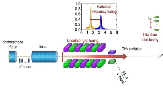
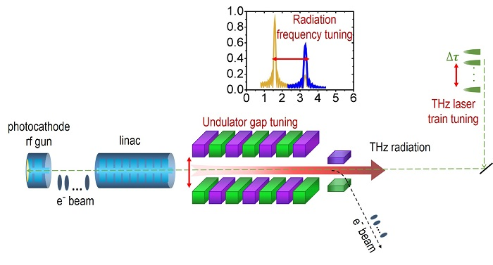
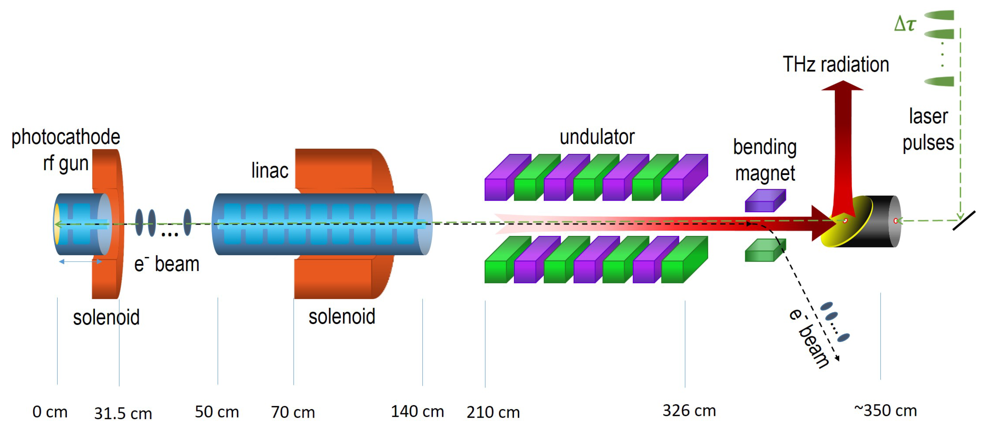
In our project, the pre-bunched THz FEL is high intensity in peak power, narrow scope in bandwidth and widely tunable in radiation frequency. It is a photoinjector-based single-pass FEL driven by a laser train with a THz interval. The electron beam is pre-bunched once emitted on the cathode, and it will excite coherent emission during the whole radiation process [11]. Figure 1 gives the overview of the facility, which is composed of a photocathode rfgun illuminated by a laser train with a THz interval, two solenoids for beam focusing, a short linear accelerator (linac) for acceleration and energy spread compensation and finally a short undulator for coherent emission. The THz source is very compact, as the total scale is about 3.5 m. The frequency adjustment is carried out mainly by varying the undulator strength together and the time interval between the laser micropulses, more straightforwardly by tuning the undulator gap and the optical delay lines of the laser.
This report is organized as follows. First, the background and THz FEL are described, and the overview of the facility is given. The main components of the apparatus are introduced in the next section. Section 3 shows the start-to-end simulation and analyzes the physical design results. Finally, a brief conclusion is given at the end.
2. Experimental Apparatus
2.1. Photocathode rf Gun
The overview of the pre-bunched THz FEL is shown in Figure 1. A photocathode rf gun is one of the most absorbing electron sources for modern accelerators, which can supply a short pulse low emittance relativistic electron beam. An electron beam pre-bunched at THz frequency is generated in the rf gun when the copper photocathode is illuminated by a THz-pulse-train laser. The use of the laser makes the photocathode an ideal choice of electron source due to the precise synchronization. A quantum efficiency of 4 × 10 is estimated [12] under a 266-nm ultraviolet (UV) light at almost normal incidence. The rf electron gun is an S-band (2856 MHz) 1.6-cell acceleration cavity with a maximum electric field on axis of approximately 120 MV/m (110 MV/m is usually adopted). An rf peak power of 15 MW can be fed into the cavity at 10–50 Hz, which is supplied by a 50-MW klystron (the remaining 35 MW is fed into the accelerating tube). At the exit of the rf gun, an electron beam with an energy of about 5 MeV, a total charge of 240 pC and a micropulse width of several tens of fs is obtained. A solenoid magnet is mounted around the electron gun to compensate the transverse beam emittance and to apply a transverse focusing on the electron beam.
2.2. Laser System
A fs laser system is used to trigger the photocathode to produce the initial electron, which is mode-locked with a sub-harmonic frequency of the 2856-MHz microwave system. The laser pulses are time-synchronized with the electron beam, as well as the driven laser. The outputs of the 800-nm oscillator laser pulses are amplified to 13 mJ in an amplifier, then converted to the UV light by a frequency tripler. Sixteen micropulses with each pulse energy larger than 200 J are transported to the copper cathode. Each micropulse has a pulse width of 30 fs in rms or 70 fs in FWHM and a smooth Gaussian profile with an rms size of 1 mm. A truncated-Gaussian laser spatial profile is proposed in consideration of a relatively small emittance with a reasonable requirement on the laser power [13], which is realized by an iris of 4 mm in diameter located upstream of the cathode. The amount of micropulses is proposed to be 16 to trade off between a high bunching factor and a low energy spread.
To realize a tunable interval time in the electron beam, the sticking point is to adjust the interval time of the THz-pulse-train laser. The laser pulse train is achieved by the pulse stacking technique [14]. A polarization beam splitter system and a phase delay system are included in the optical path. After four-stage stacking, the incident s-polarized laser pulse finally generates 16 pulses (eight s-polarized pulses and eight p-polarized pulses are alternatively stacked). The interval time between neighboring micropulses can be adjusted continuously by moving the optical delay lines.
2.3. Linear Accelerator
To satisfy the requirement of the electron energy and bunching factor (which will be discussed later) for THz FEL, the electron beam should be accelerated to the relativistic energy as soon as possible. The injector system is defined to consist of a gun for rapidly accelerating the electrons from rest, followed by a linac that increases the electron energy to 10∼18 MeV. The indicated electric field gradient of the linac is from 10–20 MV/m.
The linac is a 0.9 m-long 2856-MHz constant-gradient structure with an rf cavity of 24 cells, whose entrance is located 0.5 m downstream of the cathode. It can not only provide the electron acceleration, but also decrease the beam’s energy spread. When set to an off-crest rf phase, the linac may compensate the beam’s energy spread. At a later part of the linac is a 0.5 m-long solenoid, which focuses the beam divergence to improve the radiation characteristics. The transverse beam size should be as small as possible when the microbunches pass through the undulator downstream.
2.4. Undulator
After a sufficient acceleration with a proper energy spread compensation and also a valid focusing, the electron beam travels through an undulator to generate a coherent radiation.
In a planar undulator, the output wavelength is determined by a resonance condition:
where is the relativistic factor corresponding to the electron beam energy and and K are the period length and the strength parameter of the undulator, respectively. To obtain a THz radiation in a broad range, the undulator strength or the beam energy should be adjusted to meet the resonance condition.
A planar hybrid configuration with NdFeB material is selected as the undulator design. Since the THz wavelength is relatively long, the diffraction effect is severe, and the spot size is large. To acquire a large strength parameter with a practical consideration, the minimum undulator gap is designed to 18 mm. It should be noted that the vacuum chamber in the undulator is 70 mm and 14 mm in the horizontal and vertical, respectively. The frequency of the pre-bunched FEL ranges from 0.5–5.0 THz (the wavelength from 600–60 m), and the beam energy is from 10–18 MeV. Considering the radiation frequency and the beam energy, the undulator period is chosen as 5.8 cm. Thanks to the pre-bunched condition, a short undulator with a period number of is enough, and the total undulator length is 1.16 m. According the physical design of the electron source, the undulator entrance is located 2.1 m downstream of the cathode.
2.5. Transport Optics
The THz transfer line is installed in the space between the accelerator tunnel and the user hall. Its purpose is to transport THz radiation from the undulator exit to the first mirror at the user facility with a transmission efficiency higher than 10%. Besides, the spot diameter should be smaller than 1 cm.
Due to the building structure of the facility, we designed the transfer line as Figure 2. The overall transmission distance is about 25.4 m. Plane mirrors (M in the sketch) are smoothly-polished metals to reflect the THz beam with a typical reflectivity of 98%–99%. Off-axis paraboloids (PMs) are mirrors applied to align and focus the THz beam. It is notable that the THz optical path is in low vacuum, while the accelerator and user facility are under an ultrahigh vacuum (UHV) environment. To isolate the vacuum, a diamond window should be used to couple the radiation from the UHV chamber into the THz transfer optic, and vice versa. The two vacuum windows have apertures with a diameter of about 60 mm and 20 mm, respectively.
3. Simulation Results
3.1. Electron Beam
To improve the radiation intensity, one should enhance the bunching factor and the bunch charge simultaneously, which is restrained by the space charge effect. The design requirements of the electron source are listed in Table 1.
The electron beam consisted of 16 micropulses with a distribution determined by the driven laser. The interval time between microbunches was adjusted from 2 picoseconds (ps) to 0.33 ps, corresponding to a radiation frequency of 0.5 THz–3.0 THz. It appears difficult to satisfy the resonance condition at a higher frequency since it would require compressing the electron beam to the tens of fs level. Since the pre-bunched electron beam was highly bunched at the fundamental and second harmonic, with the harmonic generation technique, the coherent radiation frequency could be further extended to 5.0 THz by the second harmonic of a fundamental mode.
The particle tracking code ASTRA [15] with the space charge effect considered was used to compute the beam dynamics with 160,000 macro-electrons. Here, we took the microbunches spaced by 2.0 ps, 1.0 ps, 0.4 ps and 0.33 ps as samples (the corresponding fundamental frequencies are 0.5 THz, 1.0 THz, 2.5 THz and 3.0 THz, respectively). The electron energy at the frequency under 1.0 THz was designed to 10 MeV, while 18 MeV for frequency above 1.0 THz.
Figure 3 shows the longitudinal phase space of the electron beam with different interval times. The energy spreads at the gun exit and at the undulator entrance were compared, which demonstrated a good compensation by the linac. It is notable that each microbunch had a very narrow pulse width, and the interval time was a quasi-equal value, which contributed to a large bunching factor, as given in Figure 4. The large variation of the microbunch energy (energy chirp) resulted in a large energy spread of the beam, which would finally deteriorate the FEL radiation. The global energy spread decreased sharply as the interval time reduced, because the energy chirp was caused by the total occupied rf phase width by the electron beam. Therefore, the global pulse width of the electron beam was limited. The energy spread could be compensated by a linac when the beam was injected at a proper phase, which contributed to an optimal radiation output. The bunching frequency was moved to a slightly higher one due to the velocity bunching. As Figure 4c shows, the fundamental frequency was shifted from 2.5 to 2.55 THz, and the second harmonic was shifted from 5.0 to 5.11 THz. Figure 5 represents the start-to-end evolution of the rms beam size. The beam size along the undulator from 2.1–3.2 m was kept relatively small. The normalized transverse emittance of the electron beam was from 3.5 m–7.2 m, apart from the 0.5-THz case, in which the emittance was 21 m. The magnetic fields of two solenoids were set to around 1700 and 700 Gauss, respectively.
3.2. Coherent Radiation
For a certain frequency , the total power spectrum in the undulator can be expressed by [11]:
where is from the incoherent radiation of a single electron, is the total number of electrons and g is the bunching factor describing the Fourier transform of the normalized longitudinal distribution in the beam, which is:
where is the distribution function of the electron beam. The first term represents the incoherent radiation, while the second term represents the coherent undulator radiation power, which is proportional to . Thus, the pre-bunched electron beam would remarkably increase the radiation intensity since there were usually 10∼10 electrons in each beam.
Assuming the pre-bunched beam consisted of n Gaussian microbunches with an rms pulse length of and spacing by a time interval, the bunching factor can be described as:
The electron beam bunched at the fundamental frequency () and high harmonics (, m = 2, 3, ⋯) with a bandwidth of . The higher the number of microbunches was, the narrower the bandwidth. The FEL bandwidth was not only determined by the bandwidth of the bunching factor, but also the bandwidth of the FEL gain , where was the period number of the undulator. In a sufficiently long bunch, the FEL bandwidth was approximately equal to , while in a sufficiently long undulator, it was limited by [16]. Overall, to obtain intense THz radiation, one should find a resonance condition and keep the electron beam highly bunched at a THz frequency. To obtain a broad tuning in frequency, the undulator strength or the electron energy should be adjusted to meet the resonance condition, and the space between each microbunches should be tuned in a proper range.
In the following, the FEL radiation from 16 microbunches is illustrated, after being simulated by the three-dimensional code GENESIS [17]. It is worth pointing out that in the undulator, the THz divergence due to a diffraction was very obvious. As a result, the light spot increased continuously and even exceeded the vacuum boundary. According to the simulation, the light was in excess of the vacuum dimension in the vertical plane even for the 2.5-THz case. The spot size rose further for a lower frequency. The vacuum chamber acted as a waveguide for the THz FEL. We have modified the GENESIS code with the consideration of the conductive boundary conditions on the rectangular waveguide walls, which can be found elsewhere [18].
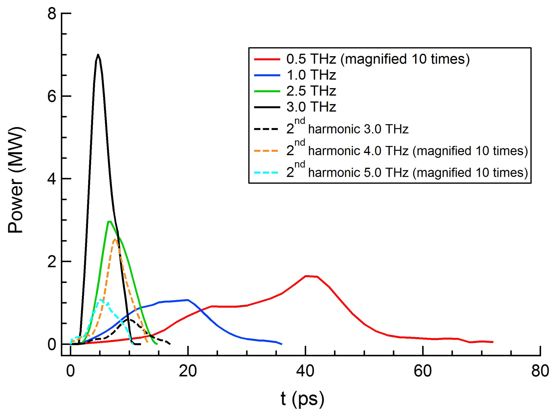
For the frequency covering 0.5–3.0 THz, the radiation was generated based on the fundamental wave of the pre-bunched beam; while the radiation covering 3.0–5.0 THz was obtained when the undulator resonated at the second harmonic of 1.5–2.5 THz. The transverse profiles are illustrated in Figure 6. The time structures and the normalized spectra of the radiation pulses at the undulator exit are compared in Figure 7 and Figure 8, respectively. Some values were magnified ten times to distinguish the curves. The radiation characteristics are summarized in Table 2. The peak radiation power was several megawatts, and the bandwidth was dominated by 1/ with a little spread. For the optimized design of the fundamental mode, a peak power of 7 MW could be realized with a pulse energy of 31 J and a bandwidth of 5.2%. The optimal radiation of fundamental mode was in the range of 2–3 THz. At lower frequency, a larger interval time between microbunches induced a larger energy spread, which caused a poor THz quality. For the second harmonic mode, the radiation power and pulse energy fell off owing to the decrease in the second harmonic bunching factor.
3.3. THz Transmission
As described in the last section, the main components of the transfer line were initial FEL light path in the undulator, two diamond windows isolating the vacuum environment in the accelerator and the user facility from the transfer optic and the transfer line including several focusing and reflecting mirrors. A MATHEMATICA code named THzTransport [19] was utilized in order to compute the shape of the radiation pulse and the THz transportation. The code was modified to calculate the intensity distribution of each cross-section and to accumulate all slices from the GENESIS output.
For a higher frequency, the diffraction effect was weaker and the difference among each slice was smaller; thus, a better transmission result could be expected. The transverse power distribution of the whole THz pulse was simulated by the superposition of all slices. The power distribution of 0.5 THz case is shown in Figure 9. There are ten 2 × 2 mm grids in each dimension in the left figure. The transmission ratio with only diffraction considered was about 42.3%. If a spot size of 10 mm in diameter were considered and a transmission ratio of 0.46 were assumed for the vacuum windows and the mirrors, the final transmission ratio would be estimated to be 12.4%.
4. Conclusions
We introduced the physical design of a pre-bunched THz FEL. A compact THz source with a peak power of a few MW (several tens of J in pulse energy), the bandwidth of a few percent, and tunable frequency range of 0.5–5 THz could be realized. The overall energy transmission ratio from the accelerator tunnel to the user hall was about 12.4%. All the design results have satisfied the requirement of the project. The technical design is in progress, and debugging and FEL output are expected in 2020.
Author Contributions
Conceptualization, Y.L. and H.L.; methodology, Z.H. and R.H.; software, W.L. and H.L.; validation, L.W. and Y.L.; formal analysis, R.H. and W.L.; investigation, Z.Z; resources, Y.L. and Q.J.; data curation, R.H., W.L. and J.W.; writing—original draft preparation, R.H.; writing—review and editing, R.H. and W.L.; visualization, T.M. and Q.H.; supervision, L.W. and Q.J.; project administration, Z.H.; funding acquisition, Y.L.
Funding
This research was funded by the National Natural Science Foundation of China Grant Number 51627901, 11675178, 11611140102, 11805200 and 11705198. This work is also supported by the National Key Research and Development Program of China Grant Number 2016YFA0401901 and the Chinese Universities Scientific Fund under Contracts WK2310000063 and WK2310000061.
Conflicts of Interest
The authors declare no conflict of interest.
Abbreviations
The following abbreviations are used in this manuscript:
| THz | terahertz |
| FEL | free electron laser |
| MW | megawatt |
| fs | femtosecond |
| linac | linear accelerator |
| UV | ultraviolet |
| PM | paraboloid |
| UHV | ultrahigh vacuum |
| ps | picosecond |
References
- Zhang, X.C.; Shkurinov, A.; Zhang, Y. Extreme terahertz science. Nat. Photonics 2017, 11, 16–18. [Google Scholar] [CrossRef]
- Pawar, A.Y.; Sonawane, D.D.; Erande, K.B.; Derle, D.V. Terahertz technology and its applications. Drug Invent. Today 2013, 5, 157–163. [Google Scholar] [CrossRef]
- Abina, A.; Puc, U.; Jeglič, A.; Zidanšek, A. Applications of terahertz spectroscopy in the field of construction and building materials. Appl. Spectrosc. Rev. 2015, 50, 279–303. [Google Scholar] [CrossRef]
- Gu, J.; Singh, R.; Tian, Z.; Cao, W.; Xing, Q.; He, M.; Zhang, J.W.; Han, J.; Chen, H.T.; Zhang, W. Terahertz superconductor metamaterial. Appl. Phys. Lett. 2010, 97, 071102. [Google Scholar] [CrossRef]
- Smye, S.W.; Chamberlain, J.M.; Fitzgerald, A.J.; Berry, E. The interaction between terahertz radiation and biological tissue. Phys. Med. Biol. 2001, 46, R101–R112. [Google Scholar] [CrossRef] [PubMed]
- Hoffmann, M.C.; Fülöp, J.A. Intense ultrashort terahertz pulses: Generation and applications. J. Phys. D Appl. Phys. 2011, 44, 083001. [Google Scholar] [CrossRef]
- Xiang, D.; Stupakov, G. Enhanced tunable narrow-band THz emission from laser-modulated electron beams. Phys. Rev. Spec. Top. Accel. Beams 2009, 12, 080701. [Google Scholar] [CrossRef]
- Dunning, M.; Hast, C.; Hemsing, E.; Jobe, K.; McCormick, D.; Nelson, J.; Raubenheimer, T.O.; Soong, K.; Szalata, Z.; Walz, D.; et al. Generating periodic terahertz structures in a relativistic electron beam through frequency down-conversion of optical lasers. Phys. Rev. Lett. 2012, 109, 074801. [Google Scholar] [CrossRef] [PubMed] [Green Version]
- Gover, A. Superradiant and stimulated-superradiant emission in prebunched electron-beam radiators. I. Formulation. Phys. Rev. Spec. Top. Accel. Beams 2005, 8, 030701. [Google Scholar] [CrossRef]
- Shen, Y.; Yang, X.; Carr, G.L.; Hidaka, Y.; Murphy, J.B.; Wang, X. Tunable few-cycle and multicycle coherent terahertz radiation from relativistic electrons. Phys. Rev. Lett. 2011, 107, 204801. [Google Scholar] [CrossRef] [PubMed]
- Li, H.; Lu, Y.; He, Z.; Jia, Q.; Wang, L. Generation of Intense Narrow-Band Tunable Terahertz Radiation from Highly Bunched Electron Pulse Train. J. Infrared Millim. Terahertz Waves 2016, 37, 649–657. [Google Scholar] [CrossRef]
- Zhou, F.; Sheppard, J.C.; Vecchione, T.; Jongewaard, E.; Brachmann, A.; Corbett, J.; Gilevich, S.; Weathersby, S. Establishing reliable good initial quantum efficiency and in-situ laser cleaning for the copper cathodes in the RF gun. Nucl. Instrum. Methods Phys. Res. Sect. A 2015, 783, 51–57. [Google Scholar] [CrossRef] [Green Version]
- Zhou, F.; Brachmann, A.; Emma, P.; Gilevich, S.; Huang, Z. Impact of the spatial laser distribution on photocathode gun operation. Phys. Rev. Spec. Top. Accel. Beams. 2012, 15, 090701. [Google Scholar] [CrossRef]
- He, Z.; Xu, Y.; Li, W.; Jia, Q. Generation of quasiequally spaced ultrashort microbunches in a photocathode rf gun. Nucl. Instrum. Methods Phys. Res. Sect. A 2015, 775, 77–83. [Google Scholar] [CrossRef]
- Floettmann, K. ASTRA User Manual. Available online: http://www.desy.de/~mpyflo/ (accessed on 30 October 2018 ).
- Huang, Y.C. Desktop megawatt superradiant free-electron laser at terahertz frequencies. Appl. Phys. Lett. 2010, 96, 231503. [Google Scholar] [CrossRef]
- Reiche, S. GENESIS 1.3: A fully 3D time-dependent FEL simulation code. Nucl. Instrum. Methods Phys. Res. Sect. A 1999, 429, 243–248. [Google Scholar] [CrossRef]
- Li, W.; Li, H.; He, Z.; Jia, Q.; Wang, L.; Lu, Y. Numerical Method for Free Electron Laser using an Overmoded Rectangular Waveguide. arXiv, 2018; arXiv:1806.00162. [Google Scholar]
- Casalbuoni, S.; Schmidt, B.; Schmüser, P.; Arsov, V.; Wesch, S. Ultrabroadband terahertz source and beamline based on coherent transition radiation. Phys. Rev. Spec. Top. Accel. Beams 2009, 12, 030705. [Google Scholar] [CrossRef]
Figure 1.
Overview of the pre-bunched THz FEL.

Figure 2.
The sketch of the THz optical path.

Figure 3.
The longitudinal phase space of sixteen microbunches at the gun exit (blue) and at the undulator entrance (red) with different interval times of (a) 2 ps, (b) 1.0 ps, (c) 0.4 ps and (d) 0.33 ps.
Figure 3.
The longitudinal phase space of sixteen microbunches at the gun exit (blue) and at the undulator entrance (red) with different interval times of (a) 2 ps, (b) 1.0 ps, (c) 0.4 ps and (d) 0.33 ps.

Figure 4.
The bunching factor of sixteen microbunches at the undulator entrance with different interval times of (a) 2 ps, (b) 1.0 ps, (c) 0.4 ps and (d) 0.33 ps.
Figure 4.
The bunching factor of sixteen microbunches at the undulator entrance with different interval times of (a) 2 ps, (b) 1.0 ps, (c) 0.4 ps and (d) 0.33 ps.

Figure 5.
The evolution of the rms beam size with different interval times of (a) 2 ps, (b) 1.0 ps, (c) 0.4 ps and (d) 0.33 ps.
Figure 5.
The evolution of the rms beam size with different interval times of (a) 2 ps, (b) 1.0 ps, (c) 0.4 ps and (d) 0.33 ps.

Figure 6.
The transverse profiles at a fundamental frequency of 0.5 THz (a), 1.0 THz (b), 2.5 THz (c), 3.0 THz (d) and second harmonics corresponding to 3.0 THz (e), 4.0 THz (f) and 5.0 THz (g).
Figure 6.
The transverse profiles at a fundamental frequency of 0.5 THz (a), 1.0 THz (b), 2.5 THz (c), 3.0 THz (d) and second harmonics corresponding to 3.0 THz (e), 4.0 THz (f) and 5.0 THz (g).

Figure 7.
The time structures at different frequencies. The power is magnified ten times for 0.5 THz, 4.0 THz and 5.0 THz.
Figure 7.
The time structures at different frequencies. The power is magnified ten times for 0.5 THz, 4.0 THz and 5.0 THz.

Figure 8.
The normalized power spectra at different frequencies. The normalized powers are magnified ten times for 4.0 THz and 5.0 THz.
Figure 8.
The normalized power spectra at different frequencies. The normalized powers are magnified ten times for 4.0 THz and 5.0 THz.

Figure 9.
The transverse radiation distribution at destination (left) and the power intensity distribution on-axis (right) for the 0.5-THz pulse. 10 × 2 mm in the left figure means there are ten 2 × 2 mm grids in each dimension.
Figure 9.
The transverse radiation distribution at destination (left) and the power intensity distribution on-axis (right) for the 0.5-THz pulse. 10 × 2 mm in the left figure means there are ten 2 × 2 mm grids in each dimension.


Table 1.
Design requirements of the electron source.
| Parameter | Value |
|---|---|
| electron energy | 11 to 18 MeV |
| microbunches | 16 |
| total charge | 240 pC |
| fundamental frequency | 0.5 to 3.0 THz |
| bunching factor | ≥0.4 |
Table 2.
Design requirements of the electron source.
| Radiation Frequency (THz) | Radiation Characteristics at Undulator Exit | ||||
|---|---|---|---|---|---|
| Peak Power (MW) | Pulse Energy (J) | Pulse Width (ps) | Radiation Bandwidth (%) | ||
| 0.5 | Fundamental wave | 0.165 | 4.01 | 72 | 19.8 |
| 1.0 | 1.07 | 18.03 | 36 | 8.5 | |
| 2.5 | 2.97 | 18.18 | 14.4 | 4.6 | |
| 3.0 | 7.00 | 31.01 | 12 | 5.2 | |
| 3.0 | 2nd harmonic wave | 0.61 | 3.83 | 17.3 | 6.8 |
| 4.0 | 0.256 | 1.21 | 13 | 6.2 | |
| 5.0 | 0.11 | 0.54 | 10.4 | 9.4 | |
© 2018 by the authors. Licensee MDPI, Basel, Switzerland. This article is an open access article distributed under the terms and conditions of the Creative Commons Attribution (CC BY) license (http://creativecommons.org/licenses/by/4.0/).
Share and Cite
MDPI and ACS Style
Huang, R.; Li, W.; Zhao, Z.; Li, H.; Wang, J.; Ma, T.; Huang, Q.; He, Z.; Jia, Q.; Wang, L.; et al. Design of a Pre-Bunched THz Free Electron Laser. Particles 2018, 1, 267-278. https://doi.org/10.3390/particles1010021
AMA Style
Huang R, Li W, Zhao Z, Li H, Wang J, Ma T, Huang Q, He Z, Jia Q, Wang L, et al. Design of a Pre-Bunched THz Free Electron Laser. Particles. 2018; 1(1):267-278. https://doi.org/10.3390/particles1010021
Chicago/Turabian StyleHuang, Ruixuan, Weiwei Li, Zhouyu Zhao, Heting Li, Jigang Wang, Tian Ma, Qiuping Huang, Zhigang He, Qika Jia, Lin Wang, and et al. 2018. "Design of a Pre-Bunched THz Free Electron Laser" Particles 1, no. 1: 267-278. https://doi.org/10.3390/particles1010021