High-Gradient Cherenkov Radiation Based on a New Dielectric-Loaded Waveguide


National Synchrotron Radiation Laboratory, University of Science and Technology of China, Hefei 230029, China
*
Authors to whom correspondence should be addressed.
Particles 2018, 1(1), 279-284; https://doi.org/10.3390/particles1010022
Submission received: 30 October 2018
/
Revised: 21 November 2018
/
Accepted: 22 November 2018
/
Published: 25 November 2018
(This article belongs to the Special Issue Superradiances from Ultra Short Electron Bunch Beam)
Abstract
:A new type of dielectric-loaded waveguide, the high-gradient dielectric-loaded waveguide (HG-DLW), where the Cherenkov radiation with a high gradient can be excited by relativistic electron, is proposed in this paper. Based on the simulation results, the process of the high-gradient Cherenkov radiation excited in the proposed structure is studied in details, and the amplitude of wakefields excited in proposed structure can be enhanced by over six times compared with that from ordinary dielectric-loaded waveguides.
1. Introduction
In recent years, dielectric-loaded waveguides (DLW), which can produce Cherenkov radiation with a narrow band when the relativistic electron passes, have generated extensive interest due to their wide applicability in various fields, including terahertz radiation sources [1,2,3], charged particle acceleration [4,5,6], beam-shaping and -bunching [7,8,9,10], and beam measurement [11]. However, due to the demand for high gradient in radiation sources and accelerating fields [12,13], many efforts have been made to enhance the wakefield gradient inside DLW. In previous reports of high-gradient radiation based on DLW, many investigators paid attention to beam manipulation to improve the coupling between field and beam. By compressing the electron bunch, a short bunch with ∼0.6 ps was achieved, and high-gradient coherent Cherenkov radiation was excited in DLW by the short bunch [1]. The ramped electron bunch was applied to excite the high-gradient Cherenkov radiation by enhancing the energy-transmission ratio [14]. The electron bunch trains with a high bunching factor could also excite the high-gradient wakefield in DLW [15].
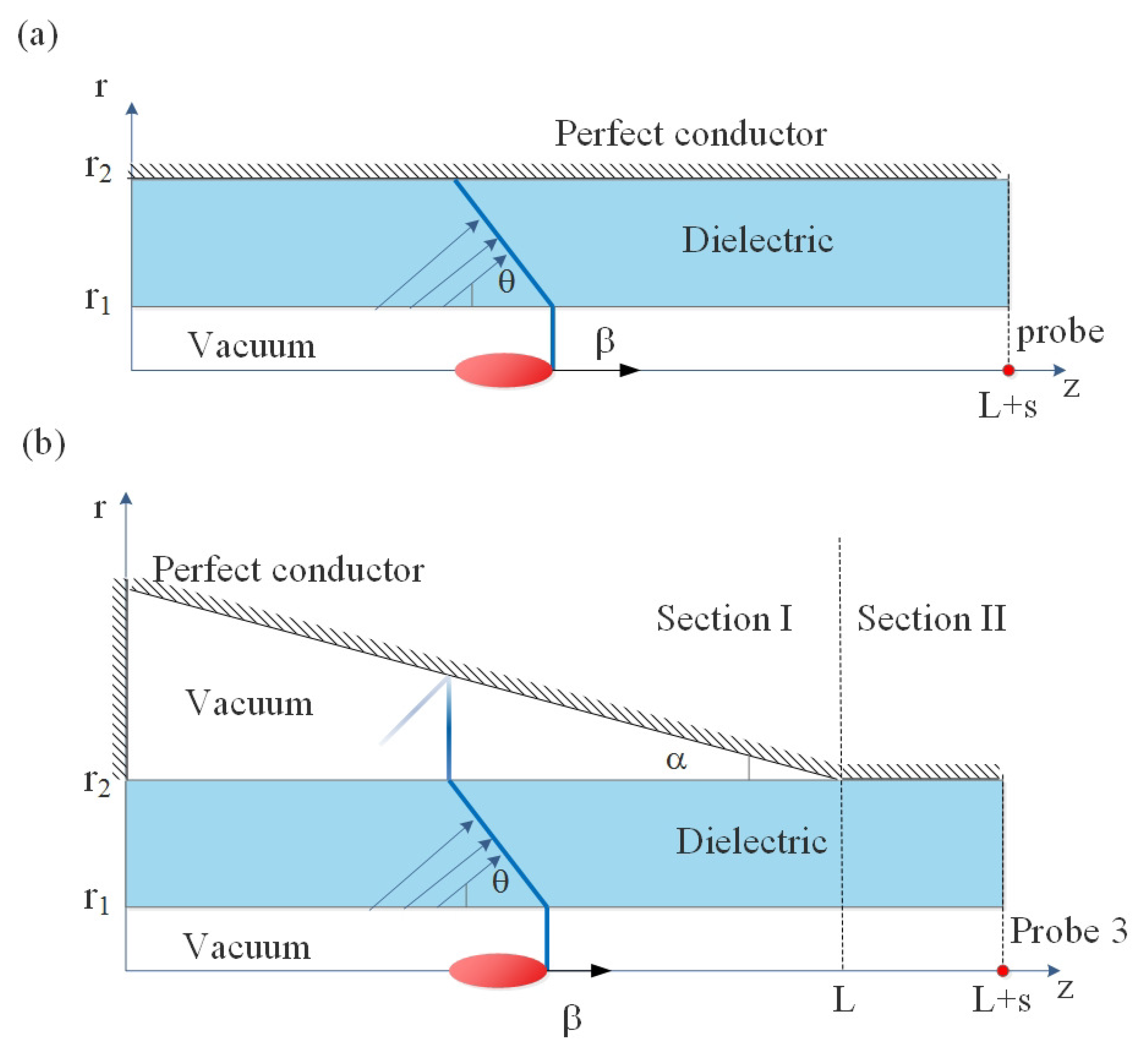
Generally, DLWs are normal conducting waveguides with a thin dielectric coating on the interior of the waveguide, as shown in Figure 1a. Compared with slab-symmetric geometry, cylindrical geometry could offer a larger coupling of the beam due to its high impedance [1,3]. By decreasing the transverse size of the waveguide, the impedance of the structure could be improved, and it also provide the benefit of a high gradient wakefield [16,17]. Thus, we just considered the case of a structure taking the cylindrical geometry to obtain the high-gradient wakefield.
In this paper, we propose a new type of dielectric-loaded waveguide, the high-gradient dielectric-loaded waveguide (HG-DLW), as shown in Figure 1b. It can produce the higher-gradient wakefield without changing the electron beam and dielectric layer. This structure contains two sections: In Section I, the dielectric layer is separated from the conductor layer, and the angle between them is ; In Section II, the structure is the same as the ordinary DLW.
As the electron goes through the Section I, the direction of the Cherenkov radiation in the dielectric layer satisfies [18]:
where is permittivity of the dielectric material, is the relative velocity of the electron, and is the angle between the directions of electron velocity and Cherenkov radiation. Due to the taper boundary, the field us reflected by the conductor and enhances the field of radiation pulse tail. Section II is the same as the DLW structure, and the wakefield excited in DLW is confined to a discrete set of modes with a narrow band, which can be given by the dispersion equation as [16]:
where and are Bessel functions of the first and second order m, is the modified Bessel function of the first kind of order m, , , and f is the frequency of field. For any Bessel functions in Equation (2), there are . After passing through this section, the wakefield is changed to narrow-band radiation as normal DLW.
By numerical simulation, we show that, compared with the ordinary DLW, the wakefield gradient can be improved in HG-DLW. With angle and length L increasing, the gradient of the wakefield can be further enhanced. According to the results, over six times improvement was achieved and it was shown that this new type of DLW could be applied to generate high-gradient Cherenkov radiation.
2. Simulation Results
To validate the statement that the excited wakefield inside HG-DLW is enhanced, numerical simulations were performed by applying the wakefield solver of a 3D electromagnetic code CST particle studio [19]. The parameters of the dielectric tube and Gaussian distribution electron bunch were constant and the same as those given in Reference [1], that is, (fused silica), mm, mm, nC, , and mm.
The first three modes, which were excited by the electron bunch in DLW with the previous parameters, could be obtained from the red intersection points in Figure 2. The frequency of the fundamental mode was 0.368 THz, and only the fundamental mode with a gradient with 14.7 MV/m could be coherently excited, as performed in Reference [1].
The processes with which electron bunches pass through the HG-DLW and DLW are shown in Figure 3, and the remained parameters of HG-DLW were selected as mm, mm. In Figure 3a, contour map is the longitudinal electric field spatial distribution before the electron bunch arrive at position of probe (0, 0, mm) in DLW (down) and HG-DLW (upper), and time evolution of the field at the probe with its spectrum was also performed. It is obvious that the main pulse of the wakefield had the larger amplitude and shorter length in the HG-DLW. Due to the taper boundary, however, the noisy field was induced when the wakefield was reflected by the outer conductor. The case in which the probe was in the position of the interface between the two section (0, 0, L) is shown in Figure 3b, the amplitude of the field increased linearly from head to tail, and the maximum of the field amplitude was 70.45 MV/m, which is around times than that of the excited wakefield in DLW. The induced noisy field could also be seen in the spectrum, but the bandwidth was narrower than the previous case. When the electron arrived at the export of the structure and the position of probe was (0, 0, ), it could be seen that the max amplitude of the field in HG-DLW shown in Figure 3c changed little compared with the results in Figure 3b. The center frequency of the field in HG-DLW equaled to that of the DLW, but the bandwidth of spectrum was large for the short pulse length. It is indicated that Section II could serve as the spectrum filter due to the limitation of DLW’s dispersion relation. On the other hand, the existence of Section II also provides the convenience to fix the conductor layer with a dielectric tube.
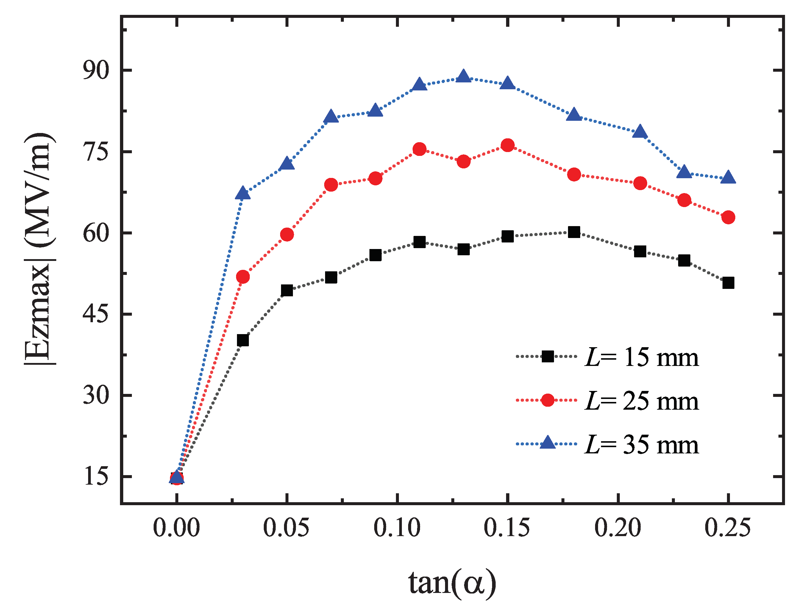
The additional parameters of the HG-DLW compared with those of DLW are , and s. Therefore, in the following analysis, we focus on the influence of these parameters on the gradient of the excited wakefield in HG-DLW. The max amplitude of longitudinal electric field variation trends in probe (0, 0, mm) in HG-DLWs with different L and different are shown in Figure 4. We can see that reached the maximum when angle reach eda certain value, but with the L increasing, the maximum of increases and the corresponding angles decreased. When = 0.13 and L = 35 mm, = 88.6 MV/m, which is over six times than that in the case of (corresponding to the case of ordinary DLW). By optimizing parameters including L and , the wakefield with a higher gradient can also be realized.
The time evolution of field in the export of HG-DLWs with different s is shown in Figure 5. By increasing the length of Section II, the wakefield pulse became longer. However, when the high-gradient field induced by Section I arrived at the end of Section II, the max amplitude of the field decreased. If the s were small, amplitude would change little, but the gradient decline would be severe if the length of Section II were too long. For satisfying the requirement of a single mode with narrow band and avoiding losing too much energy, length L could be selected as ∼ (the fundamental mode wavelength of wakefield in Section II).
3. Conclusions
In this paper, we proposed a new type of dielectric-loaded waveguide, the HG-DLW, and investigated the coherent Cherenkov radiation scheme based on this new structure. It was verified that HG-DLW could effectively enhance the gradient of the wakefield excited by a relativistic electron bunch compared with the results of an ordinary DLW. By increasing the length of the structure or angle between the conductor and dielectric layers, the maximum of the radiation-field amplitude could be enhanced. The improvement of the gradient by six times was shown in the simulation results. The results confirmed that HG-DLW could be a practical structure to produce high-gradient Cherenkov radiation.
Author Contributions
Conceptualization, S.J. and W.L.; methodology, S.J. and Z.H.; validation, W.L. and Z.H.; investigation, S.J. and W.L.; writing—original draft preparation, S.J.; writing—review and editing, W.L., Z.H. and Q.J.; visualization, S.J.; supervision, W.L., Z.H. and Q.J.; funding acquisition, W.L., Z.H. and Q.J.
Funding
This research was funded by the National Foundation of Natural Sciences of China (11705198, 11775216, 11675178, 11611140102), the China Postdoctoral Science Foundation (2017M622023), and the Fundamental Research Funds for the Central Universities (WK2310000061).
Conflicts of Interest
The authors declare no conflict of interest.
References
- Cook, A.; Tikhoplav, R.; Tochitsky, S.Y.; Travish, G.; Williams, O.; Rosenzweig, J. Observation of narrow-band terahertz coherent Cherenkov radiation from a cylindrical dielectric-lined waveguide. Phys. Rev. Lett. 2009, 103, 095003. [Google Scholar] [CrossRef] [PubMed]
- Altmark, A.; Kanareykin, A. The source of THz radiation based on dielectric waveguide excited by sequence of electron bunches. J. Phys. Conf. Ser. 2016, 732, 012037. [Google Scholar] [CrossRef] [Green Version]
- Wiggins, S.; Jaroszynski, D.; McNeil, B.; Robb, G.; Aitken, P.; Phelps, A.; Cross, A.; Ronald, K.; Ginzburg, N.; Shpak, V.; et al. Self-amplification of coherent spontaneous emission in a Cherenkov free-electron maser. Phys. Rev. Lett. 2000, 84, 2393. [Google Scholar] [CrossRef] [PubMed]
- Nie, Y.; Assmann, R.; Dorda, U.; Marchetti, B.; Weikum, M.; Zhu, J.; Hüning, M. Potential applications of the dielectric wakefield accelerators in the SINBAD facility at DESY. Nucl. Instrum. Methods Phys. Res. Sect. A Accel. Spectrometers Detect. Assoc. Equip. 2016, 829, 183–186. [Google Scholar] [CrossRef] [Green Version]
- Jing, C. Dielectric wakefield accelerators. Rev. Accel. Sci. Technol. 2016, 9, 127–149. [Google Scholar] [CrossRef]
- O’Shea, B.; Andonian, G.; Barber, S.; Fitzmorris, K.; Hakimi, S.; Harrison, J.; Hoang, P.; Hogan, M.; Naranjo, B.; Williams, O.; et al. Observation of acceleration and deceleration in gigaelectron-volt-per-metre gradient dielectric wakefield accelerators. Nat. Commun. 2016, 7, 12763. [Google Scholar] [CrossRef] [PubMed] [Green Version]
- Antipov, S.; Jing, C.; Kanareykin, A.; Butler, J.E.; Yakimenko, V.; Fedurin, M.; Kusche, K.; Gai, W. Experimental demonstration of wakefield effects in a THz planar diamond accelerating structure. Appl. Phys. Lett. 2012, 100, 132910. [Google Scholar] [CrossRef] [Green Version]
- Antipov, S.; Babzien, M.; Jing, C.; Fedurin, M.; Gai, W.; Kanareykin, A.; Kusche, K.; Yakimenko, V.; Zholents, A. Subpicosecond bunch train production for a tunable mJ level THz source. Phys. Rev. Lett. 2013, 111, 134802. [Google Scholar] [CrossRef] [PubMed]
- Lemery, F.; Piot, P. Ballistic bunching of photoinjected electron bunches with dielectric-lined waveguides. Phys. Rev. Spec. Top.-Accel. Beams 2014, 17, 112804. [Google Scholar] [CrossRef]
- Piot, P. Overview of Alternative Bunching and Current-Shaping Techniques for Low-Energy Electron Beams. Technical Report. 2015. Available online: http://accelconf.web.cern.ch/AccelConf/FEL2015/papers/mod02.pdf (accessed on 24 November 2018).
- Bettoni, S.; Craievich, P.; Lutman, A.; Pedrozzi, M. Temporal profile measurements of relativistic electron bunch based on wakefield generation. Phys. Rev. Accel. Beams 2016, 19, 021304. [Google Scholar] [CrossRef]
- Ferguson, B.; Zhang, X.C. Materials for terahertz science and technology. Nat. Mater. 2002, 1, 26–33. [Google Scholar] [CrossRef] [PubMed]
- Curry, E.; Fabbri, S.; Maxson, J.; Musumeci, P.; Gover, A. Meter-Scale Terahertz-Driven Acceleration of a Relativistic Beam. Phys. Rev. Lett. 2018, 120, 094801. [Google Scholar] [CrossRef] [PubMed] [Green Version]
- Jing, C.; Power, J.; Conde, M.; Liu, W.; Yusof, Z.; Kanareykin, A.; Gai, W. Increasing the transformer ratio at the Argonne wakefield accelerator. Phys. Rev. Spec. Top-Accel. Beams 2011, 14, 021302. [Google Scholar] [CrossRef]
- Wang, D.; Antipov, S.; Jing, C.; Power, J.; Conde, M.; Wisniewski, E.; Liu, W.; Qiu, J.; Ha, G.; Dolgashev, V.; et al. Interaction of an ultrarelativistic electron bunch train with a W-band accelerating structure: High power and high gradient. Phys. Rev. Lett. 2016, 116, 054801. [Google Scholar] [CrossRef] [PubMed]
- Park, S.; Hirshfield, J. Theory of wakefields in a dielectric-lined waveguide. Phys. Rev. E 2000, 62, 1266. [Google Scholar] [CrossRef]
- Baturin, S.; Kanareykin, A. Cherenkov radiation from short relativistic bunches: General approach. Phys. Rev. Lett. 2014, 113, 214801. [Google Scholar] [CrossRef] [PubMed]
- Frank, I.; Tamm, I. Coherent visible radiation of fast electrons passing through matter. In Selected Papers; Springer: New York, NY, USA, 1991; pp. 29–35. [Google Scholar]
- Corp, C. CST PS Tutorials. Available online: http://www.cst-china.cn/ (accessed on 27 October 2018).
Figure 1.
Scheme of a (a) normal dielectric-loaded waveguide (DLW) and (b) high-gradient DLW (HG-DLW).
Figure 1.
Scheme of a (a) normal dielectric-loaded waveguide (DLW) and (b) high-gradient DLW (HG-DLW).

Figure 2.
Dispersion curves (black dash curve) that were obtained from Equation (2) and the electron velocity line (red solid line).
Figure 2.
Dispersion curves (black dash curve) that were obtained from Equation (2) and the electron velocity line (red solid line).

Figure 3.
Simulation results of contour maps of longitudinal electric field , time evolution of longitudinal electric field , field spectrum in ordinary HG-DLW ( mm, mm) and DLW in three probes with (a) (0, 0, mm), (b) (0, 0, L), (c) (0, 0, ).
Figure 3.
Simulation results of contour maps of longitudinal electric field , time evolution of longitudinal electric field , field spectrum in ordinary HG-DLW ( mm, mm) and DLW in three probes with (a) (0, 0, mm), (b) (0, 0, L), (c) (0, 0, ).

Figure 4.
Max amplitude of longitudinal electric field in probe (0, 0, mm) in HG-DLWs with different angle in cases of L = 15 mm, L = 25 mm, and L = 35 mm.
Figure 4.
Max amplitude of longitudinal electric field in probe (0, 0, mm) in HG-DLWs with different angle in cases of L = 15 mm, L = 25 mm, and L = 35 mm.

Figure 5.
Time evolutions of longitudinal electric field in the export of HG-DLW in the cases of mm, mm, and mm.
Figure 5.
Time evolutions of longitudinal electric field in the export of HG-DLW in the cases of mm, mm, and mm.

© 2018 by the authors. Licensee MDPI, Basel, Switzerland. This article is an open access article distributed under the terms and conditions of the Creative Commons Attribution (CC BY) license (http://creativecommons.org/licenses/by/4.0/).
Share and Cite
MDPI and ACS Style
Jiang, S.; Li, W.; He, Z.; Jia, Q. High-Gradient Cherenkov Radiation Based on a New Dielectric-Loaded Waveguide. Particles 2018, 1, 279-284. https://doi.org/10.3390/particles1010022
AMA Style
Jiang S, Li W, He Z, Jia Q. High-Gradient Cherenkov Radiation Based on a New Dielectric-Loaded Waveguide. Particles. 2018; 1(1):279-284. https://doi.org/10.3390/particles1010022
Chicago/Turabian StyleJiang, Shimin, Weiwei Li, Zhigang He, and Qika Jia. 2018. "High-Gradient Cherenkov Radiation Based on a New Dielectric-Loaded Waveguide" Particles 1, no. 1: 279-284. https://doi.org/10.3390/particles1010022