
Magnetoelectric Sensor Operating in d15 Thickness-Shear Mode for High-Frequency Current Detection

 , , , , , ,
Abstract
1. Introduction
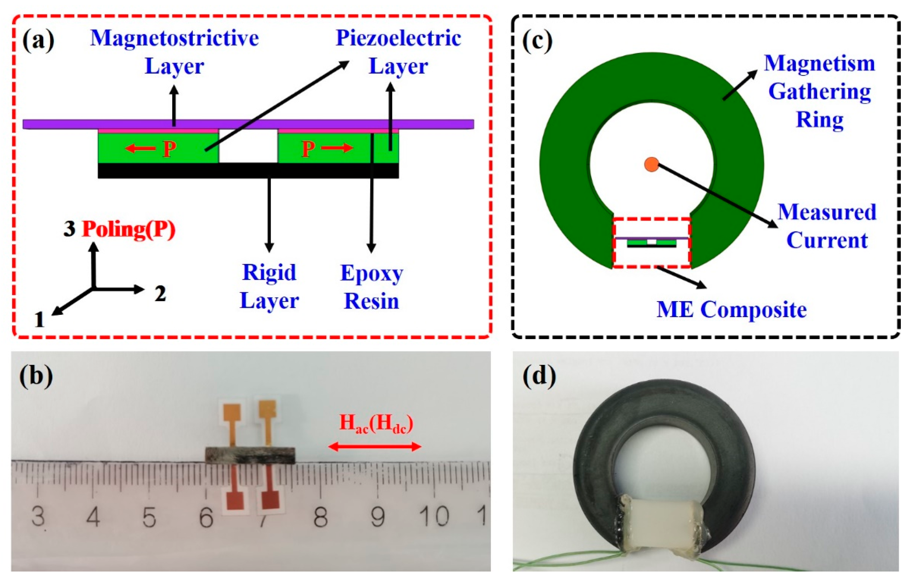
2. Device Design and Fabrication
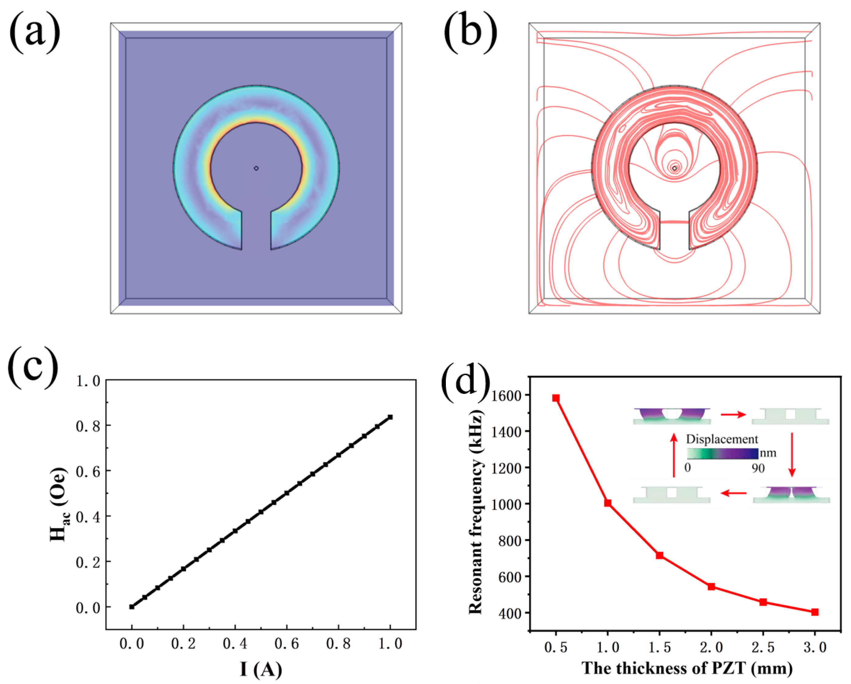
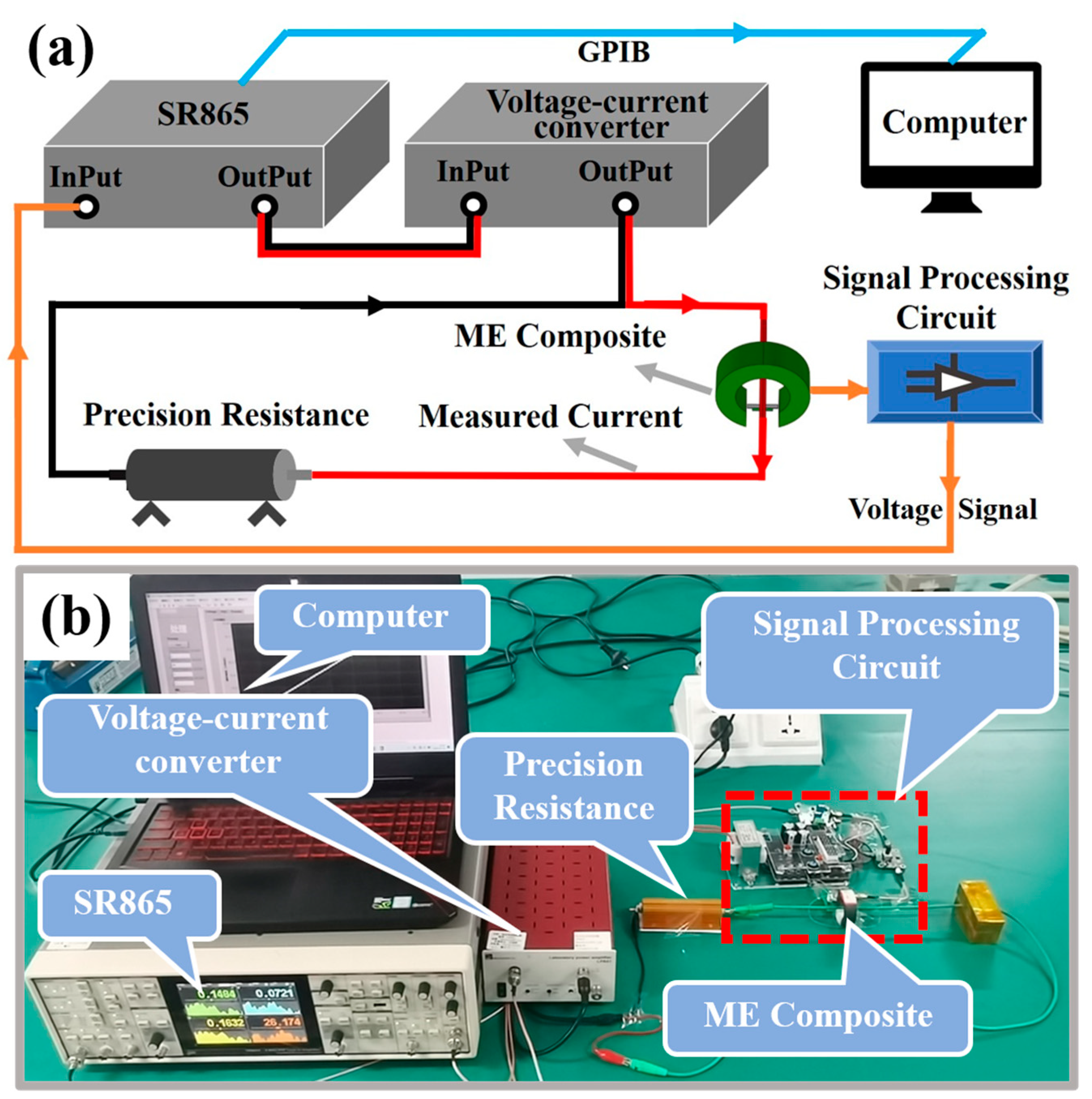
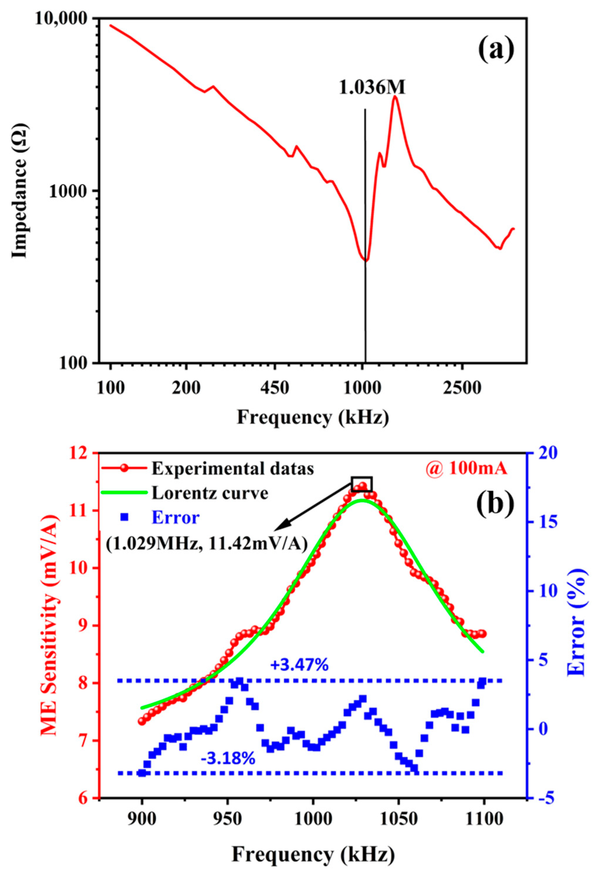
3. Results and Discussion
4. Conclusions
Author Contributions
Funding
Institutional Review Board Statement
Informed Consent Statement
Data Availability Statement
Conflicts of Interest
References
- Colak, L. Introduction to smart grid. In Proceedings of the 2016 International Smart Grid Workshop and Certificate Program (ISGWCP), Istanbul, Turkey, 21–25 March 2016; pp. 30–34. [Google Scholar]
- Farhangi, H. The path of the smart grid. IEEE Power Energy Mag. 2010, 8, 18–28. [Google Scholar] [CrossRef]
- Watekar, P.R.; Yang, H.; Ju, S.; Han, W.T. Enhanced current sensitivity in the optical fiber doped with CdSe quantum dots. Opt. Express 2009, 17, 3157–3164. [Google Scholar] [CrossRef] [PubMed]
- Shede, P.; Mane, S. Leakage current sensing techniques. In Proceedings of the 2017 Third International Conference on Sensing, Signal Processing and Security (ICSSS), Chennai, India, 4–5 October 2017; pp. 181–184. [Google Scholar]
- Ma, X.; Li, W.; Wang, X.; Yang, M.; Gao, Z.; Zhao, Y. Calibration of measuring network of leakage current tester by high frequency current source. In Proceedings of the 2018 Conference on Precision Electromagnetic Measurements (CPEM 2018), Paris, France, 8–13 July 2018; pp. 1–2. [Google Scholar]
- Wang, D.; Du, L.; Wang, S.; Ran, L. Self-powered lightning current sensor. In Proceedings of the 2016 IEEE Sensors, Orlando, FL, USA, 30 October–3 November 2016; pp. 1–3. [Google Scholar]
- Mei, H.; Shi, Y.; Zhao, C.; Wang, L. Research on lightning current sensor coil based on lightning space magnetic field. IEEE Trans. Instrum. Meas. 2018, 67, 1922–1928. [Google Scholar] [CrossRef]
- Pastre, M.; Kayal, M.; Blanchard, H. A hall sensor analog front end for current measurement with continuous gain calibration. IEEE Sens. J. 2007, 7, 860–867. [Google Scholar] [CrossRef]
- Zaidi, S.; Tatam, R. Faraday-effect magnetometry: Compensation for the temperature-dependent Verdet constant. Meas. Sci. Technol. 1994, 5, 1471–1479. [Google Scholar] [CrossRef]
- Cesa, T.; Driggans, J.; Weikel, S. Optical voltage and current sensors used in a revenue metering system. IEEE Trans. Power Delivery 1991, 6, 1374–1379. [Google Scholar]
- Paun, M.A.; Sallese, J.M.; Kayal, M. Temperature considerations on Hall Effect sensors current related sensitivity behaviour. Analog Integr. Circ. Sig. Process 2013, 77, 355–364. [Google Scholar] [CrossRef]
- Mellet, D.S.; Plessis, M. A novel CMOS Hall effect sensor. Sens. Actuators A Phys. 2014, 211, 60–66. [Google Scholar] [CrossRef][Green Version]
- Kayal, M.; Pastre, M. Automatic calibration of Hall sensor microsystems. Microelectron J. 2006, 37, 1569–1575. [Google Scholar] [CrossRef]
- Chen, W.; Du, F.; Zhao, Y.; Anheuser, M. A new type of hall current sensor. In Proceedings of the 2011 IEEE International Instrumentation and Measurement Technology Conference, Hangzhou, China, 10–12 May 2011; pp. 867–870. [Google Scholar]
- Pastre, M.; Pastre, M. A hall sensor-based current measurement microsystem with continuous gain calibration. In Proceedings of the International Conference on PhD Research in Microelectronics and Electronics (PRIME 2005), Lausanne, Switzerland, 25–28 July 2005; pp. 295–298. [Google Scholar]
- Togawa, K.; Sanbonsugi, H.; Lapicki, A.; Abe, M.; Handa, H.; Sandhu, A. High-sensitivity InSb thin-film micro-Hall sensor arrays for simultaneous multiple detection of magnetic beads for biomedical applications. IEEE Trans. Magn. 2005, 41, 3661–3663. [Google Scholar] [CrossRef]
- Groenenboom, M.; Lisser, J. Accurate measurement of DC and AC by transformer. Electron. Power 1977, 23, 52–55. [Google Scholar] [CrossRef]
- Ramboz, J.D. Machinable Rogowski coil, design, and calibration. IEEE Trans. Instrum. Meas. 1996, 45, 511–515. [Google Scholar] [CrossRef]
- Ward, D.A.; Exon, J.L.T. Using Rogowski coils for transient current measurements. Eng. Sci. Educ. J. 1993, 2, 105–113. [Google Scholar] [CrossRef]
- Samimi, M.H.; Mahari, A.; Farahnakian, M.A.; Mohseni, H. The Rogowski Coil Principles and Applications: A Review. IEEE Sens. J. 2015, 15, 651–658. [Google Scholar] [CrossRef]
- Wang, L.; Hu, Z.; Wu, J.; Zhao, X.; Guan, M.; Wang, C.; Luo, N.; Xian, D.; Wang, Z.; Zhou, Z.; et al. Enhancing the Linearity of Giant Magnetoresistance Sensors by Magnetic Anisotropic Design and Low Temperature Annealing. IEEE Sens. J. 2021, 21, 27393–27399. [Google Scholar] [CrossRef]
- Su, W.; Wang, Z.; Wen, T.; Hu, Z.; Wu, J.; Zhou, Z.; Liu, M. Linear Anisotropic Magnetoresistive Sensor Without Barber-Pole Electrodes. IEEE Electr. Device Lett. 2019, 40, 969–972. [Google Scholar] [CrossRef]
- Chu, Z.; Shi, H.; Shi, W.; Liu, G.; Wu, J.; Yang, J.; Dong, S. Enhanced Resonance Magnetoelectric Coupling in (1-1) Connectivity Composites. Adv. Mater. 2017, 29, 1606022. [Google Scholar] [CrossRef]
- Chu, Z.; PourhosseiniAsl, M.; Dong, S. Review of multi-layered magnetoelectric composite materials and devices applications. J. Phys. D Appl. Phys. 2018, 51, 243001. [Google Scholar] [CrossRef]
- Wu, J.; Du, Y.; Xu, Y.; Qiao, J.; Qu, Y.; Wang, Z.; Dong, S.; Hu, Z.; Liu, M. Self-biased magnetoelectric sensor operating in d36 face-shear mode. IEEE Sens. J. 2023, 23, 22366–22372. [Google Scholar] [CrossRef]
- Zhou, S.Z.; Gao, X.X. Magnetostrictive Materials, 1st ed.; Metallurgical Industry Press: Beijing, China, 2017; pp. 7–9. [Google Scholar]
- Wang, C.L.; Li, J.C.; Zhao, M.L. Piezoelectric Ferroelectric Physics, 1st ed.; Science Press: Beijing, China, 2009; pp. 61–63. [Google Scholar]
- Luan, G.D.; Zhang, J.D.; Wang, R.Q. Piezoelectric Transducers and Arrays, 1st ed.; Peking University Press: Beijing, China, 2005; pp. 93–95. [Google Scholar]
- Thakur, P.; Chahar, D.; Taneja, S.; Bhalla, N.; Thakur, A. A review on MnZn ferrites: Synthesis, characterization and applications. Ceram. Int. 2020, 46, 15740–15763. [Google Scholar] [CrossRef] [PubMed]
- Tan, X.; Li, W.; Xu, X.; Ao, G.; Zhou, F.; Zhao, J.; Tan, Q.; Zhang, W. Contactless AC/DC Wide-Bandwidth Current Sensor Based on Composite Measurement Principle. Sensors 2022, 22, 7979. [Google Scholar] [CrossRef] [PubMed]
- Sánchez, J.; Ramírez, D.; Ravelo, S.I.; Lopes, A.; Cardoso, S.; Ferreira, R.; Freitas, P.P. Electrical Characterization of a Magnetic Tunnel Junction Current Sensor for Industrial Applications. IEEE T. Magn. 2012, 48, 2823–2826. [Google Scholar] [CrossRef]
- Tröster, N.; Dominkoviü, B.; Wölfle, J.; Fischer, M.; Roth-Stielow, J. Wide Bandwidth Current Probe for Power Electronics Using Tunneling Magnetoresistance Sensors. In Proceedings of the 2017 IEEE 12th International Conference on Power Electronics and Drive Systems (PEDS), Honolulu, HI, USA, 12–15 December 2017; pp. 35–40. [Google Scholar]
- Zhou, H.; Chen, J.; Fang, Y.; Xu, Z.; Chang, K.; Yu, G.; Zhu, M.; Qiu, Y. Ultrasensitive Modulated Magnetoelectric Sensors and Low-Noise Readout Circuits for DC and Very Low-Frequency Weak Magnetic Signal Detection. IEEE Sens. J. 2023, 23, 13019–13027. [Google Scholar] [CrossRef]
- Qiu, Y.; Shi, L.; Chen, L.; Yu, Y.; Yu, G.; Zhu, M.; Zhou, H. A Wide-Band Magnetoelectric Sensor Based on a Negative-Feedback Compensated Readout Circuit. Sensors 2024, 24, 423. [Google Scholar] [CrossRef] [PubMed]
- Leung, C.M.; Or, S.W.; Zhang, S.; Ho, S.L. Ring-type electric current sensor based on ring-shaped magnetoelectric laminate of epoxy-bonded Tb0.3Dy0.7Fe1.92 short-fiber/NdFeB magnet magnetostrictive composite and Pb(Zr, Ti)O3 piezoelectric ceramic. J. Appl. Phys. 2010, 107, 09D918. [Google Scholar] [CrossRef]
- Zhang, J.; Li, P.; Wen, Y.; He, W.; Yang, A.; Lu, C. Packaged current-sensing device with self-biased magnetoelectric laminate for low-frequency weak-current detection. Smart Mater. Struct. 2014, 23, 095028. [Google Scholar] [CrossRef]
- Ou, Z.; Lu, C.; Yang, A.; Zhou, H.; Cao, Z.; Zhu, R.; Gao, H. Self-biased magnetoelectric current sensor based on SrFe12O19/FeCuNbSiB/PZT composite. Sens. Actuators A Phys. 2019, 290, 8–13. [Google Scholar] [CrossRef]
- Lu, C.; Li, P.; Wen, Y.; Yang, A.; Yang, C.; Wang, D.; He, W.; Zhang, J. Zero-biased magnetoelectric composite Fe73.5Cu1Nb3Si13.5B9/Ni/Pb(Zr1−x, Tix)O3 for current sensing. J. Alloys. Comp. 2014, 589, 498–501. [Google Scholar] [CrossRef]
- Shi, Z.; Tong, Y.; Deng, S.; Xue, H.; Yang, S.; Lu, Y.; Wang, C.; Liu, X. Magnetoelectric sensor with miniature universal tunable bias magnetic circuit. Appl. Phys. Lett. 2013, 103, 032903. [Google Scholar] [CrossRef]
- Castro, N.; Reis, S.; Silva, M.P.; Correia, V.; Lanceros-Mendez, S.; Martins, P. Development of a contactless DC current sensor with high linearity and sensitivity based on the magnetoelectric effect. Smart Mater. Struct. 2018, 27, 065012. [Google Scholar] [CrossRef]
- Guo, X.; Yu, X.; Lou, G. A wide range DC current sensor based on disk-type magnetoelectric laminate composite with a feedback circuit. In Proceedings of the 2017 IEEE Sensors, Glasgow, UK, 29 October–1 November 2017; pp. 1–3. [Google Scholar]
- Bauer, M.J.; Thomas, A.; Isenberg, B.; Varela, J.; Faria, A.; Arnold, D.P.; Andrew, J.S. Ultra-low-power current sensor utilizing magnetoelectric nanowires. IEEE Sens. J. 2020, 20, 5139–5145. [Google Scholar] [CrossRef]
- Yu, X.; Lou, G.; Chen, H.; Wen, C.; Lu, S. A slice-type magnetoelectric laminated current sensor. IEEE Sens. J. 2015, 15, 5839–5850. [Google Scholar] [CrossRef]
- Bichurin, M.; Petrov, R.; Leontiev, V.; Semenov, G.; Sokolov, O. Magnetoelectric current sensors. Sensors 2017, 17, 1271. [Google Scholar] [CrossRef] [PubMed]
- Huong Giang, D.T.; Tam, H.A.; Ngoc Khanh, V.T.; Vinh, N.T.; Anh Tuan, P.; Van Tuan, N.; Thi Ngoc, N.; Duc, N.H. Magnetoelectric vortex magnetic field sensors based on the metglas/PZT laminates. Sensors 2020, 20, 2810. [Google Scholar] [CrossRef] [PubMed]
- Zhang, M.; Or, S.W. Gradient-type magnetoelectric current sensor with strong multisource noise suppression. Sensors 2018, 18, 588. [Google Scholar] [CrossRef] [PubMed]


| Component | Measuring Range | Sensitivity (mV/A) | Working Frequency | Reference |
|---|---|---|---|---|
| Terfenol-D/PZT | 0.01–2 A | 12.6 | 1 Hz–30 kHz | [35] |
| Terfenol-D/PZT | 0.01–100 A | 152 | 50 Hz | [36] |
| Metglas/PZT | 0.01–5 A | 198.91 | 50 Hz | [37] |
| Metglas/Ni/PZT | 0–2 A | 330 | 50 Hz | [38] |
| Ni/PZT | 0.2–740 A | 0.042 | 50 Hz | [39] |
| Metglas/PVDF | 0–5 A | 476.5 | 28.4 kHz | [40] |
| Terfenol-D/PZT | 0–1000 A | 1.014 | 1 kHz | [41] |
| NZFO/PZT | 0–0.08 A | 3.24 | 1 kHz | [42] |
| Terfenol-D/PZT | 0.015–2.1 A | 1.03 | 50 Hz–5000 Hz | [43] |
| Metglas/PZT | 0–5 A | 340 | 1 kHz | [44] |
| Metglas/PZT | 0–4 A | 5426 | 174.4 kHz | [45] |
| Terfenol-D/PZT | 0–20 A | 0.65–12.55 | 10 Hz–170 kHz | [46] |
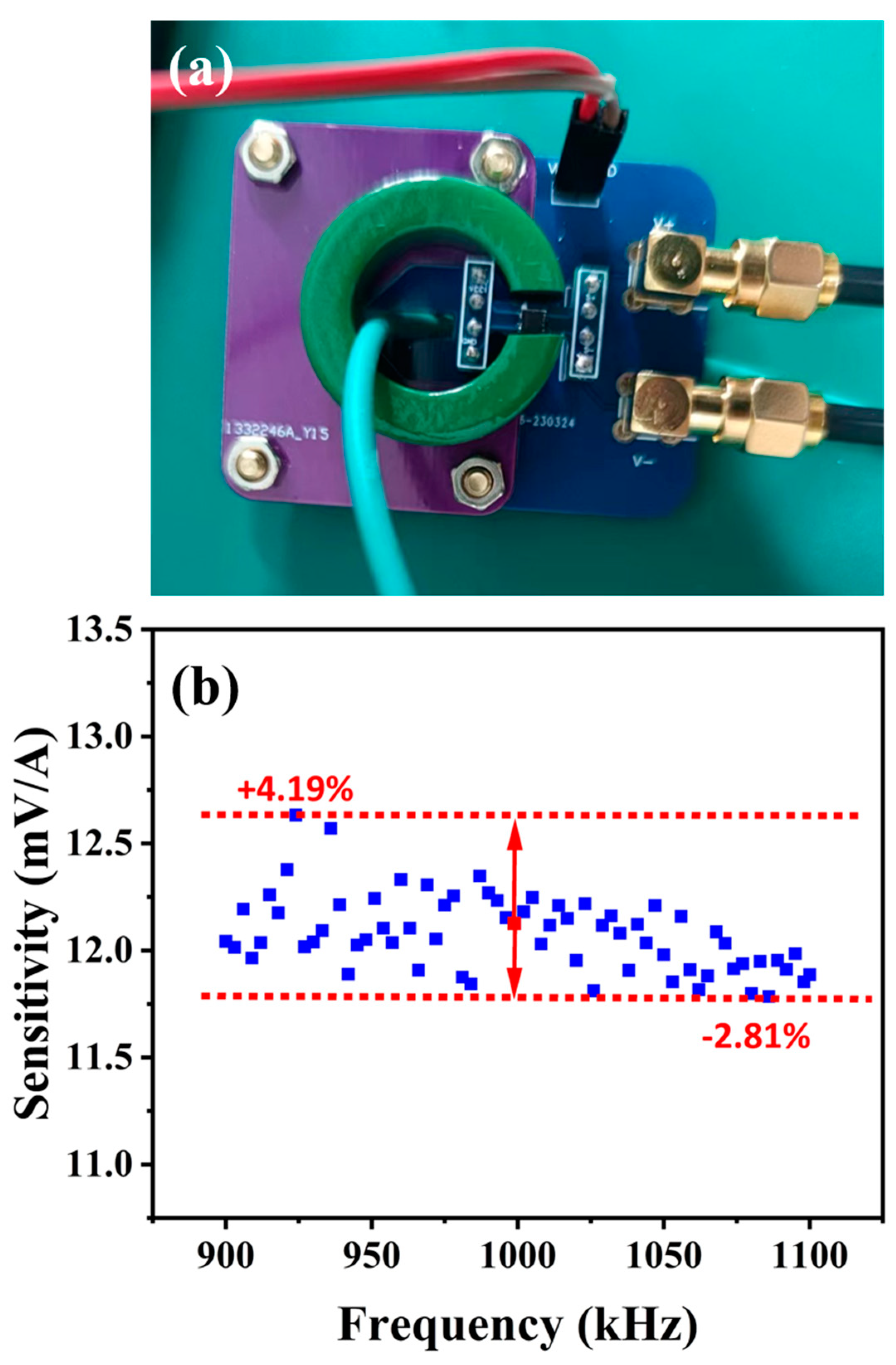
| Metglas/PZT | 3.28 μA–0.5 A | 7.33~11.4 | 900 kHz–1100 kHz | This work |
Disclaimer/Publisher’s Note: The statements, opinions and data contained in all publications are solely those of the individual author(s) and contributor(s) and not of MDPI and/or the editor(s). MDPI and/or the editor(s) disclaim responsibility for any injury to people or property resulting from any ideas, methods, instructions or products referred to in the content. |
© 2024 by the authors. Licensee MDPI, Basel, Switzerland. This article is an open access article distributed under the terms and conditions of the Creative Commons Attribution (CC BY) license (https://creativecommons.org/licenses/by/4.0/).
Share and Cite
Li, F.; Wu, J.; Liu, S.; Gao, J.; Lin, B.; Mo, J.; Qiao, J.; Xu, Y.; Du, Y.; He, X.; et al. Magnetoelectric Sensor Operating in d15 Thickness-Shear Mode for High-Frequency Current Detection. Sensors 2024, 24, 2396. https://doi.org/10.3390/s24082396
Li F, Wu J, Liu S, Gao J, Lin B, Mo J, Qiao J, Xu Y, Du Y, He X, et al. Magnetoelectric Sensor Operating in d15 Thickness-Shear Mode for High-Frequency Current Detection. Sensors. 2024; 24(8):2396. https://doi.org/10.3390/s24082396
Chicago/Turabian StyleLi, Fuchao, Jingen Wu, Sujie Liu, Jieqiang Gao, Bomin Lin, Jintao Mo, Jiacheng Qiao, Yiwei Xu, Yongjun Du, Xin He, and et al. 2024. "Magnetoelectric Sensor Operating in d15 Thickness-Shear Mode for High-Frequency Current Detection" Sensors 24, no. 8: 2396. https://doi.org/10.3390/s24082396
APA StyleLi, F., Wu, J., Liu, S., Gao, J., Lin, B., Mo, J., Qiao, J., Xu, Y., Du, Y., He, X., Zhou, Y., Zeng, L., Hu, Z., & Liu, M. (2024). Magnetoelectric Sensor Operating in d15 Thickness-Shear Mode for High-Frequency Current Detection. Sensors, 24(8), 2396. https://doi.org/10.3390/s24082396