
Cardiac Magnetic Resonance and Cardiac Implantable Electronic Devices: Are They Truly Still “Enemies”?

 ,
,  , , , ,
  ,
, 
Abstract
:1. Introduction
2. Brief Overview of Cardiac Magnetic Resonance
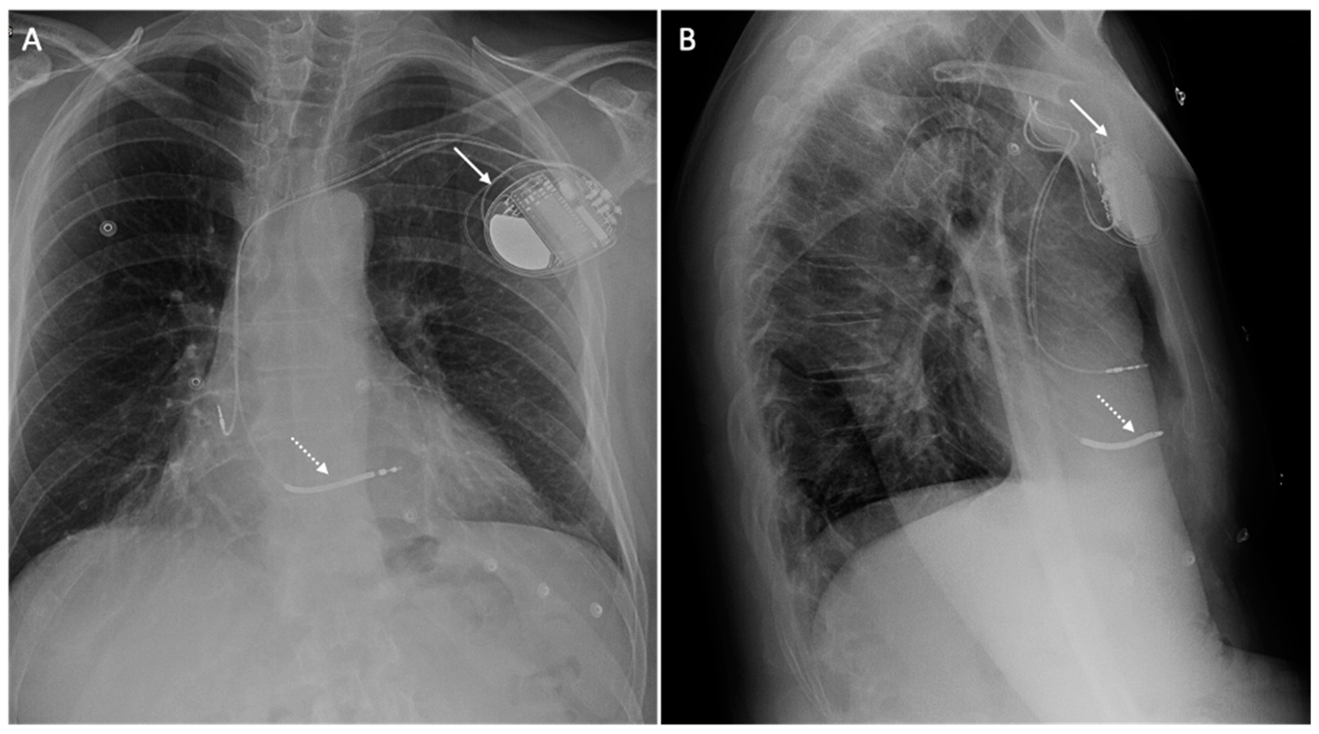
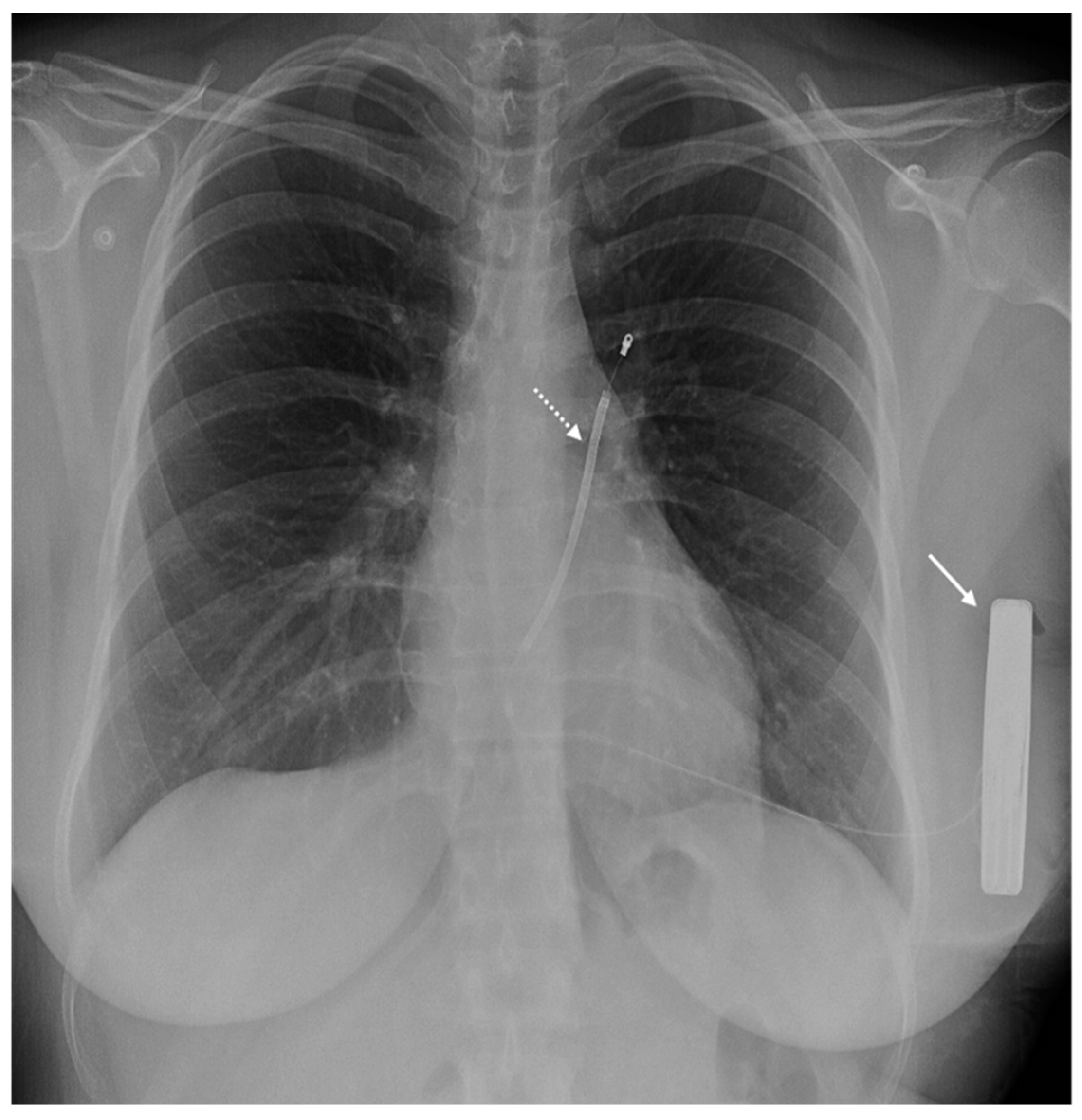
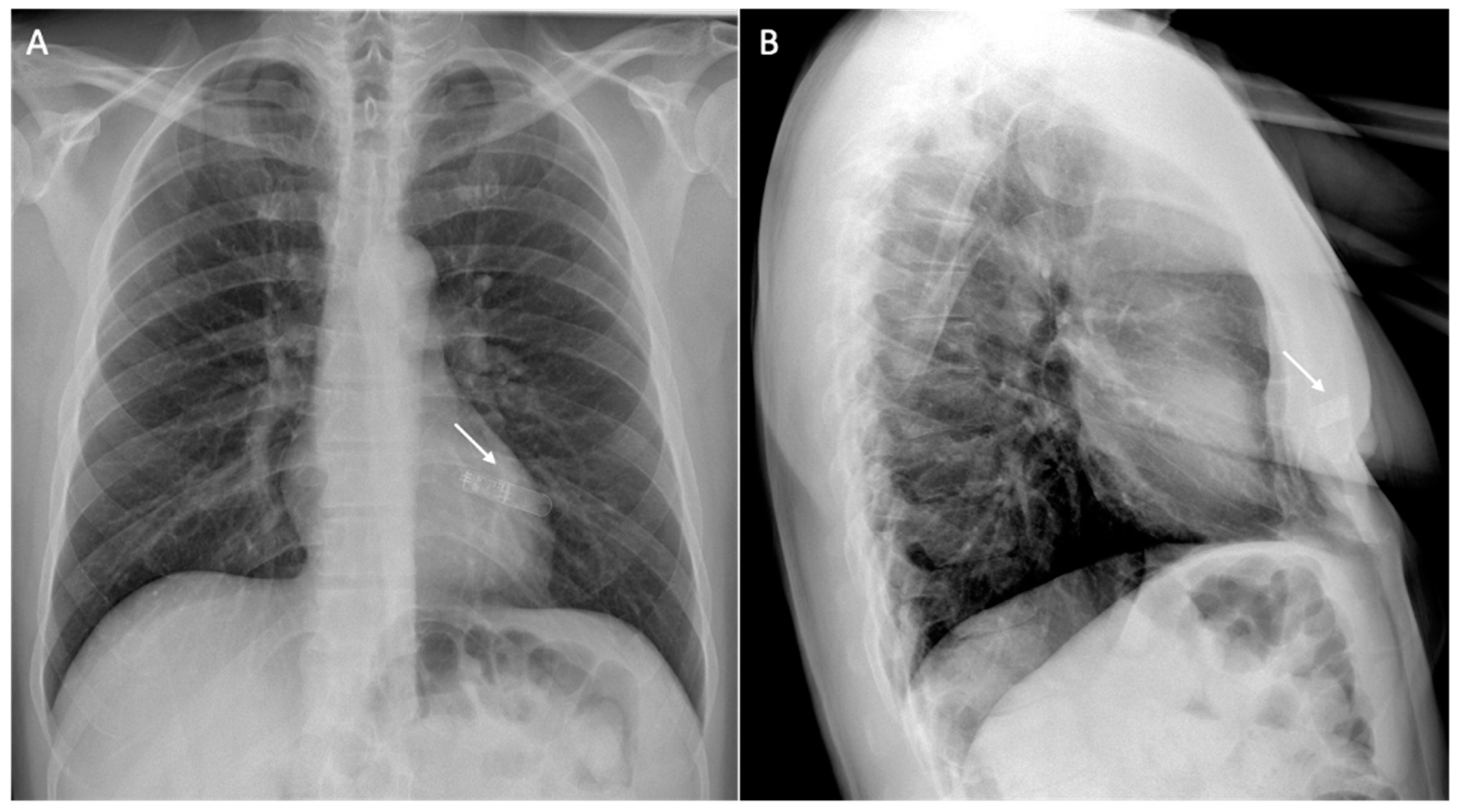
3. Brief Overview of Cardiac Implantable Electronic Devices
4. Safety Considerations
5. Issue: Safety
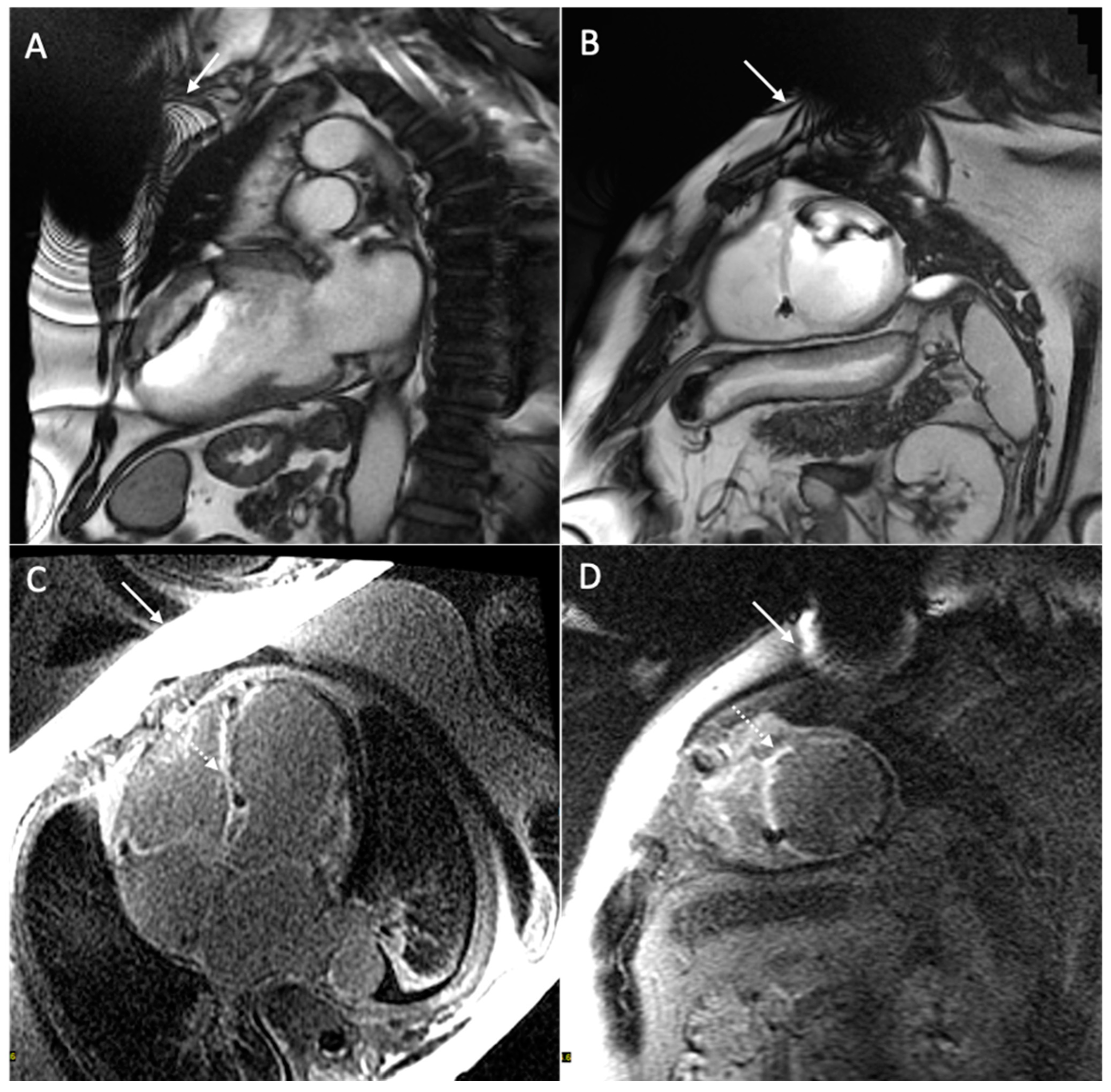
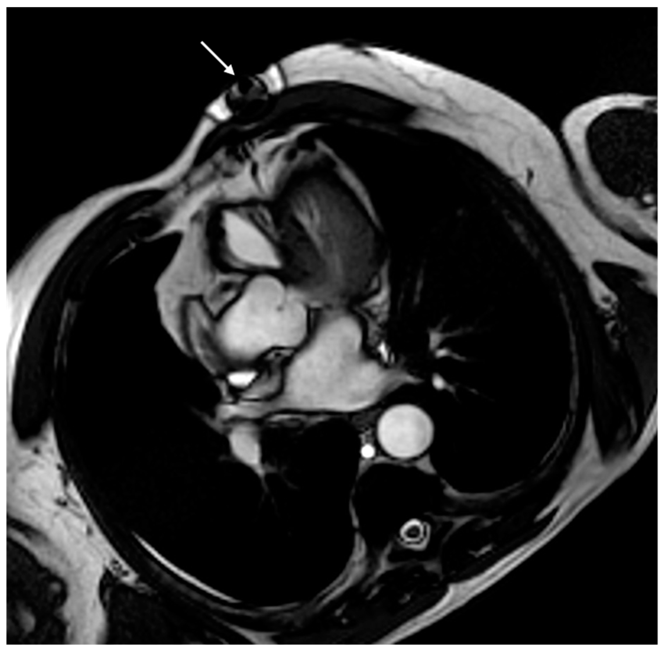
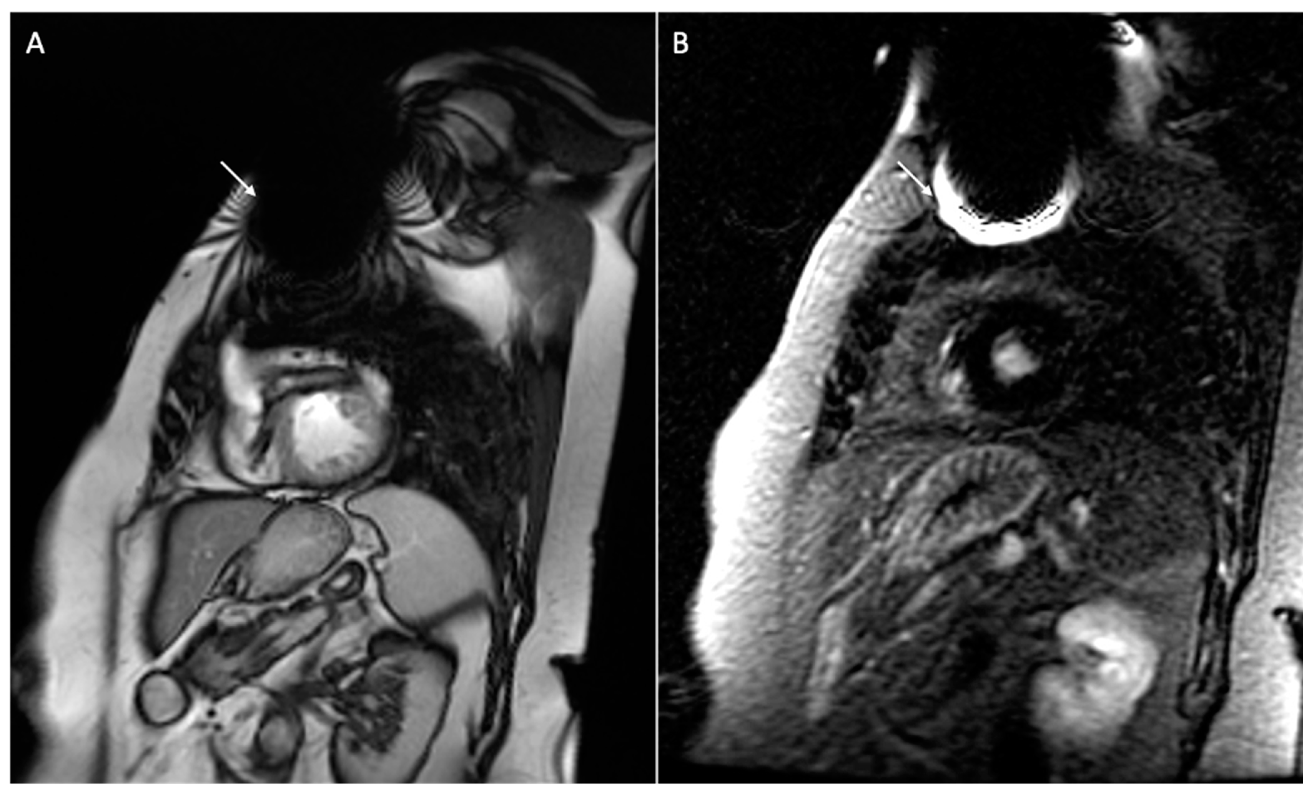
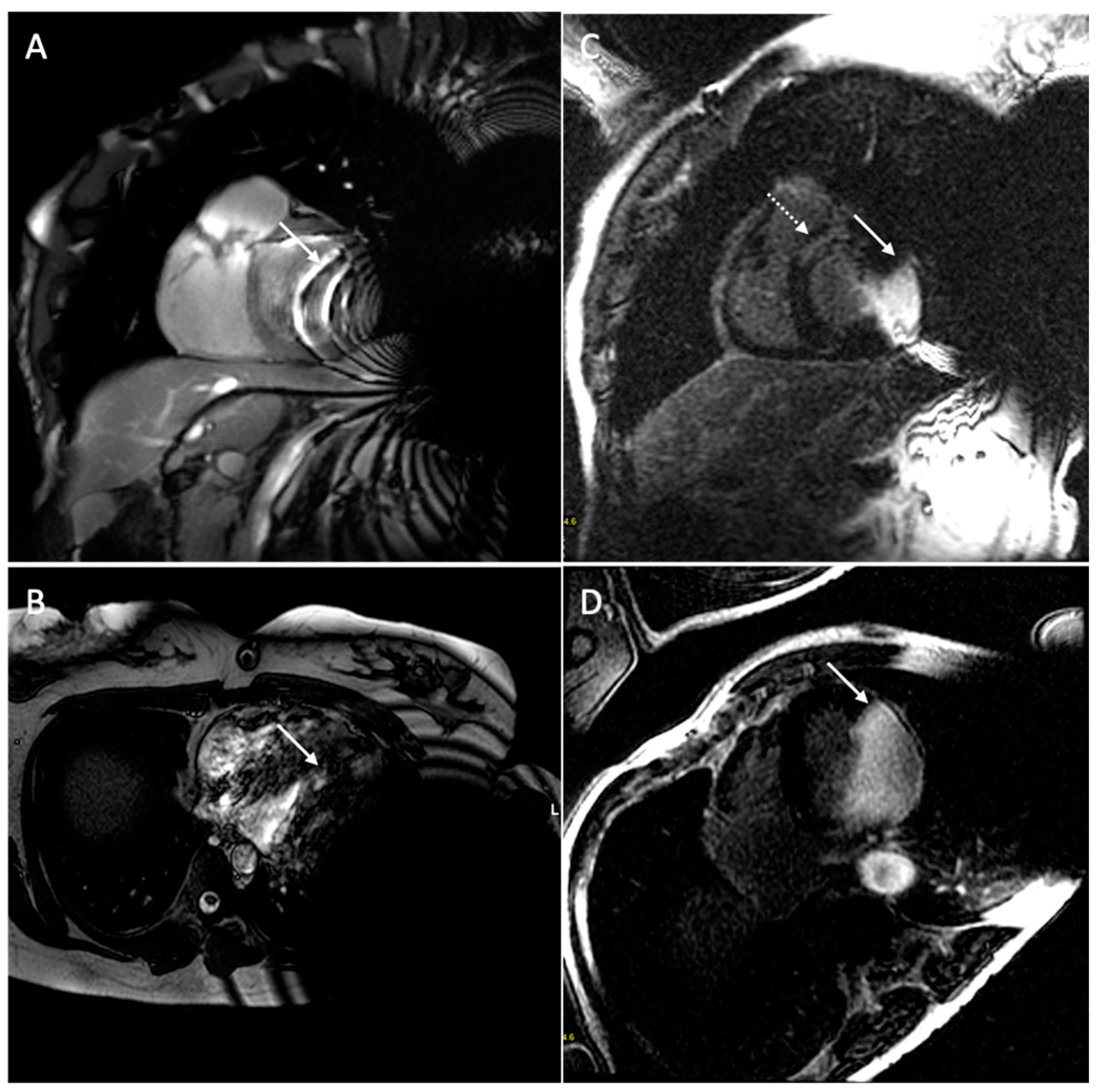
6. Issue: Artifact
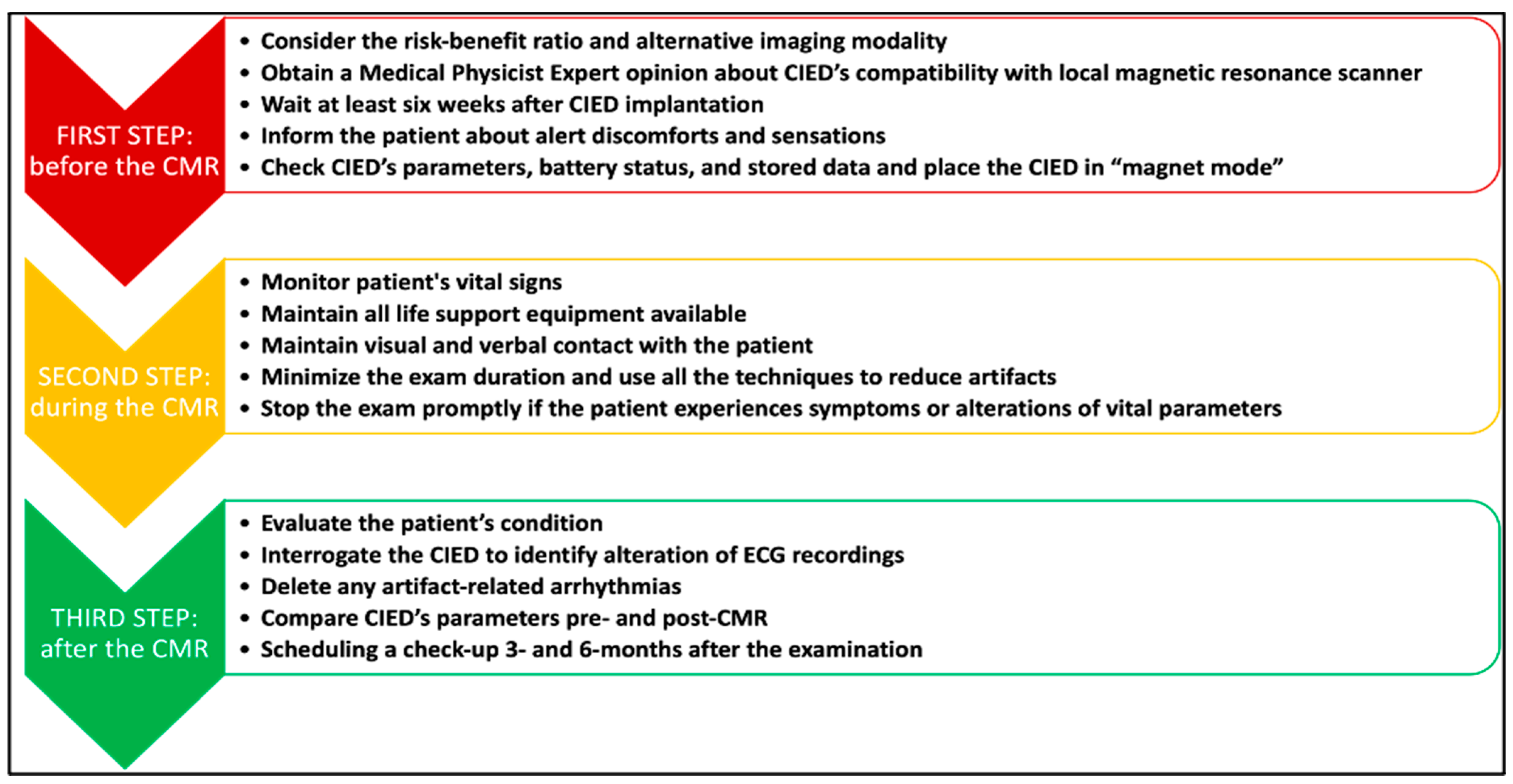
7. Clinical Protocol for Patients with CIEDs Undergoing CMR
8. Alternative Imaging Modalities to CMR
9. Conclusions
Author Contributions
Funding
Institutional Review Board Statement
Informed Consent Statement
Data Availability Statement
Conflicts of Interest
References
- Holtackers, R.J.; Wildberger, J.E.; Wintersperger, B.J.; Chiribiri, A. Impact of Field Strength in Clinical Cardiac Magnetic Resonance Imaging. Investig. Radiol. 2021, 56, 764–772. [Google Scholar] [CrossRef]
- Liu, C.; Ferrari, V.A.; Han, Y. Cardiovascular Magnetic Resonance Imaging and Heart Failure. Curr. Cardiol. Rep. 2021, 23, 35. [Google Scholar] [CrossRef]
- Rajiah, P.S.; François, C.J.; Leiner, T. Cardiac MRI: State of the Art. Radiology 2023, 307, e223008. [Google Scholar] [CrossRef] [PubMed]
- Nazir, M.S.; Okafor, J.; Murphy, T.; Andres, M.S.; Ramalingham, S.; Rosen, S.D.; Chiribiri, A.; Plein, S.; Prasad, S.; Mohiaddin, R.; et al. Echocardiography versus Cardiac MRI for Measurement of Left Ventricular Ejection Fraction in Individuals with Cancer and Suspected Cardiotoxicity. Radiol. Cardiothorac. Imaging 2024, 6, e230048. [Google Scholar] [CrossRef]
- Mavrogeni, S.I.; Kallifatidis, A.; Kourtidou, S.; Lama, N.; Christidi, A.; Detorakis, E.; Chatzantonis, G.; Vrachliotis, T.; Karamitsos, T.; Kouskouras, K.; et al. Cardiovascular magnetic resonance for the evaluation of patients with cardiovascular disease: An overview of current indications, limitations, and procedures. Hell. J. Cardiol. 2023, 70, 53–64. [Google Scholar] [CrossRef] [PubMed]
- Papanastasiou, C.A.; Kokkinidis, D.G.; Jonnalagadda, A.K.; Oikonomou, E.K.; Kampaktsis, P.N.; Garcia, M.J.; Myerson, S.G.; Karamitsos, T.D. Meta-Analysis of Transthoracic Echocardiography Versus Cardiac Magnetic Resonance for the Assessment of Aortic Regurgitation After Transcatheter Aortic Valve Implantation. Am. J. Cardiol. 2019, 124, 1246–1251. [Google Scholar] [CrossRef] [PubMed]
- Silva, T.Q.A.C.; Pezel, T.; Jerosch-Herold, M.; Coelho-Filho, O.R. The Role and Advantages of Cardiac Magnetic Resonance in the Diagnosis of Myocardial Ischemia. J. Thorac. Imaging 2023, 38, 235–246. [Google Scholar] [CrossRef] [PubMed]
- Thomas, K.E.; Fotaki, A.; Botnar, R.M.; Ferreira, V.M. Imaging Methods: Magnetic Resonance Imaging. Circ. Cardiovasc. Imaging 2023, 16, e014068. [Google Scholar] [CrossRef]
- Bazmpani, M.A.; Nikolaidou, C.; Papanastasiou, C.A.; Ziakas, A.; Karamitsos, T.D. Cardiovascular Magnetic Resonance Parametric Mapping Techniques for the Assessment of Chronic Coronary Syndromes. J. Cardiovasc. Dev. Dis. 2022, 9, 443. [Google Scholar] [CrossRef] [PubMed]
- Di Marco, A.; Claver, E.; Anguera, I. Impact of Cardiac Magnetic Resonance to Arrhythmic Risk Stratification in Nonischemic Cardiomyopathy. Card. Electrophysiol. Clin. 2023, 15, 379–390. [Google Scholar] [CrossRef]
- Tran, H.H.-V.; Sherpa, M.L.; Shrestha, N.; Ravi, N.; Choday, S.; Kumar, V.S.; Kc, A.; Parisapogu, A.; Ojinna, B.T.; Mohammed, L. Safety and Efficacy of an Implantable Cardioverter Defibrillator (ICD) in the Detection and Prevention of Cardiac Arrhythmia—A Systematic Review. Cureus 2023, 15, e48471. [Google Scholar] [CrossRef]
- Okada, D.R.; Wu, K.C. Applications of Cardiac MR Imaging in Electrophysiology: Current Status and Future Needs. Magn. Reson. Imaging Clin. N. Am. 2019, 27, 465–473. [Google Scholar] [CrossRef]
- Yeung, S.S.T.; Clark, M.; Loshak, H. Magnetic Resonance Imaging for Patients with Implantable Cardiac Devices: A Review of Safety and Guidelines; Canadian Agency for Drugs and Technologies in Health: Ottawa, ON, USA, 2019.
- Deshpande, S.; Kella, D.; Padmanabhan, D. MRI in patients with cardiac implantable electronic devices: A comprehensive review. Pacing Clin. Electrophysiol. 2021, 44, 360–372. [Google Scholar] [CrossRef]
- Barison, A.; Baritussio, A.; Cipriani, A.; De Lazzari, M.; Aquaro, G.D.; Guaricci, A.I.; Pica, S.; Pontone, G.; Todiere, G.; Indolfi, C.; et al. Cardiovascular magnetic resonance: What clinicians should know about safety and contraindications. Int. J. Cardiol. 2021, 331, 322–328. [Google Scholar] [CrossRef]
- Talle, M.A.; Doubell, A.F.; Robbertse, P.-P.S.; Lahri, S.; Herbst, P.G. Cardiac Morphology, Function, and Left Ventricular Geometric Pattern in Patients with Hypertensive Crisis: A Cardiovascular Magnetic Resonance-Based Study. J. Cardiovasc. Dev. Dis. 2023, 10, 367. [Google Scholar] [CrossRef]
- Xu, Y.; Li, Y.; Wang, S.; Wan, K.; Tan, Y.; Li, W.; Wang, J.; Guo, J.; Ghaithan, S.; Cheng, W.; et al. Prognostic Value of Mid-term Cardiac Magnetic Resonance Follow-up in Patients with Non-ischemic Dilated Cardiomyopathy: A prospective cohort study. J. Cardiovasc. Magn. Reson. 2024, 26, 101002. [Google Scholar] [CrossRef]
- Compagnucci, P.; Volpato, G.; Falanga, U.; Cipolletta, L.; Conti, M.A.; Grifoni, G.; Ciliberti, G.; Stronati, G.; Fogante, M.; Bergonti, M.; et al. Myocardial Inflammation, Sports Practice, and Sudden Cardiac Death: 2021 Update. Medicina 2021, 57, 277. [Google Scholar] [CrossRef] [PubMed]
- Gerber, B.L. Review and critical appraisal of the indications for cardiac magnetic resonance imaging in the ESC guidelines. Acta Cardiol. 2023, 79, 5–19. [Google Scholar] [CrossRef] [PubMed]
- Gräni, C.; Benz, D.C.; Gupta, S.; Windecker, S.; Kwong, R.Y. Sudden Cardiac Death in Ischemic Heart Disease: From Imaging Arrhythmogenic Substrate to Guiding Therapies. JACC Cardiovasc. Imaging 2020, 13, 2223–2238. [Google Scholar] [CrossRef] [PubMed]
- Casella, M.; Bergonti, M.; Dello Russo, A.; Maragna, R.; Gasperetti, A.; Compagnucci, P.; Catto, V.; Trombara, F.; Frappampina, A.; Conte, E.; et al. Endomyocardial Biopsy: The Forgotten Piece in the Arrhythmogenic Cardiomyopathy Puzzle. J. Am. Heart Assoc. 2021, 10, e021370. [Google Scholar] [CrossRef] [PubMed]
- Franke, K.B.; Marshall, H.; Kennewell, P.; Pham, H.-D.; Tully, P.J.; Rattanakosit, T.; Mahadevan, G.; Mahajan, R. Risk and predictors of sudden death in cardiac sarcoidosis: A systematic review and meta-analysis. Int. J. Cardiol. 2021, 328, 130–140. [Google Scholar] [CrossRef]
- Bandettini, W.P.; Kwong, R.Y.; Patel, A.R.; Plein, S.; Society for Cardiovascular Magnetic Resonance. Society for Cardiovascular Magnetic Resonance perspective on the ACC/AHA/ASE/ASNC/ASPC/HFSA/HRS/SCAI/SCCT/SCMR/STS 2023 multi-modality appropriate use criteria for the detection and risk assessment of chronic coronary disease. J Cardiovasc. Magn. Reson. 2023, 25, 59. [Google Scholar] [CrossRef]
- Fogante, M.; Agliata, G.; Basile, M.C.; Compagnucci, P.; Volpato, G.; Falanga, U.; Stronati, G.; Guerra, F.; Vignale, D.; Esposito, A.; et al. Cardiac Imaging in Athlete’s Heart: The Role of the Radiologist. Medicina 2021, 57, 455. [Google Scholar] [CrossRef]
- Majmudar, M.D.; Nahrendorf, M. Cardiovascular molecular imaging: The road ahead. J. Nucl. Med. 2012, 53, 673–676. [Google Scholar] [CrossRef]
- Mavrogeni, S.I.; Sfikakis, P.P.; Koutsogeorgopoulou, L.; Markousis-Mavrogenis, G.; Dimitroulas, T.; Kolovou, G.; Kitas, G.D. Cardiac Tissue Characterization and Imaging in Autoimmune Rheumatic Diseases. JACC Cardiovasc. Imaging 2017, 10, 1387–1396. [Google Scholar] [CrossRef]
- Xu, F.; Meng, L.; Lin, H.; Xu, W.; Guo, H.; Peng, F. Systematic review of leadless pacemaker. Acta Cardiol. 2023, 14, 1–11. [Google Scholar] [CrossRef]
- Saeed, A.; AlShafea, A.; AlQthami, M.; Bin Saeed, A.; AlAhmri, F.A.; AlQahtani, N.S.; Al-Muslat, F.A.; AlQahtani, A. A Systematic Review and Meta-analysis of the Prevalence and Risk Factors in Cardiac Implantable Electronic Device Malfunction. J. Saudi Heart Assoc. 2023, 35, 311–334. [Google Scholar] [CrossRef] [PubMed]
- Gulletta, S.; Schiavone, M.; Gasperetti, A.; Breitenstein, A.; Palmisano, P.; Mitacchione, G.; Chierchia, G.B.; Montemerlo, E.; Statuto, G.; Russo, G.; et al. Peri-procedural and mid-term follow-up age-related differences in leadless pacemaker implantation: Insights from a multicenter European registry. Int. J. Cardiol. 2023, 371, 197–203. [Google Scholar] [CrossRef]
- McGee, M.J.; Ray, M.; Brienesse, S.C.; Sritharan, S.; Boyle, A.J.; Jackson, N.; Leitch, J.W.; Sverdlov, A.L. Remote monitoring in patients with heart failure with cardiac implantable electronic devices: A systematic review and meta-analysis. Open Heart 2022, 9, e002096. [Google Scholar] [CrossRef] [PubMed]
- Aguilera, J.; Hutt, E.; Jaber, W.A. Imaging of Cardiac Device-Related Infection. Front. Cardiovasc. Med. 2021, 8, 729786. [Google Scholar] [CrossRef] [PubMed]
- Gasperetti, A.; Schiavone, M.; Ziacchi, M.; Vogler, J.; Breitenstein, A.; Laredo, M.; Palmisano, P.; Ricciardi, D.; Mitacchione, G.; Compagnucci, P.; et al. Long-term complications in patients implanted with subcutaneous implantable cardioverter-defibrillators: Real-world data from the extended ELISIR experience. Heart Rhythm. 2021, 18, 2050–2058. [Google Scholar] [CrossRef] [PubMed]
- Edvardsson, N.; Garutti, C.; Rieger, G.; Linker, N.J.; PICTURE Study Investigators. Unexplained syncope: Implications of age and gender on patient characteristics and evaluation, the diagnostic yield of an implantable loop recorder, and the subsequent treatment. Clin. Cardiol. 2014, 37, 618–625. [Google Scholar] [CrossRef] [PubMed]
- Gasperetti, A.; Schiavone, M.; Ziacchi, M.; Vogler, J.; Breitenstein, A.; Laredo, M.; Palmisano, P.; Ricciardi, D.; Mitacchione, G.; Compagnucci, P.; et al. Role of Outpatient Cardiac Rhythm Monitoring in Cryptogenic Stroke: A Systematic Review and Meta-Analysis. Pacing Clin. Electrophysiol. 2015, 38, 1236–1245. [Google Scholar] [CrossRef]
- Gasperetti, A.; Schiavone, M.; Ziacchi, M.; Vogler, J.; Breitenstein, A.; Laredo, M.; Palmisano, P.; Ricciardi, D.; Mitacchione, G.; Compagnucci, P.; et al. Recurrence of atrial fibrillation postablation: Which is the most effective approach for detection? Minerva Cardiol. Angiol. 2022, 70, 628–638. [Google Scholar] [CrossRef]
- Roberts, P.R.; Stromberg, K.; Johnson, L.C.; Wiles, B.M.; Mavrakanas, T.A.; Charytan, D.M. A Systematic Review of the Incidence of Arrhythmias in Hemodialysis Patients Undergoing Long-Term Monitoring with Implantable Loop Recorders. Kidney Int. Rep. 2021, 6, 56–65. [Google Scholar] [CrossRef]
- Evidence Review Committee Members; Varosy, P.D.; Chen, L.Y.; Miller, A.L.; Noseworthy, P.A.; Slotwiner, D.J.; Thiruganasambandamoorthy, V. Pacing as a treatment for reflex-mediated (vasovagal, situational, or carotid sinus hypersensitivity) syncope: A systematic review for the 2017 ACC/AHA/HRS guideline for the evaluation and management of patients with syncope: A report of the American College of Cardiology/American Heart Association Task Force on Clinical Practice Guidelines and the Heart Rhythm Society. Heart Rhythm. 2017, 14, e255–e269. [Google Scholar] [CrossRef]
- Yang, E.; Suzuki, M.; Nazarian, S.; Halperin, H.R. Magnetic resonance imaging safety in patients with cardiac implantable electronic devices. Trends Cardiovasc. Med. 2022, 32, 440–447. [Google Scholar] [CrossRef]
- Watson, R.E.; Edmonson, H.A. MR Safety: Active Implanted Electronic Devices. Magn. Reson. Imaging Clin. N. Am. 2020, 28, 549–558. [Google Scholar] [CrossRef]
- Auricchio, A.; Faletra, F.F. Use of Contemporary Imaging Techniques for Electrophysiological and Device Implantation Procedures. JACC Cardiovasc. Imaging 2020, 13, 851–865. [Google Scholar] [CrossRef]
- Michowitz, Y.; Kronborg, M.B.; Glikson, M.; Nielsen, J.C. 2021 ESC Guidelines on cardiac pacing and cardiac resynchronization therapy. Eur. Heart J. 2021, 42, 3427–3520. [Google Scholar] [CrossRef]
- Luechinger, R.; Duru, F.; Scheidegger, M.B.; Boesiger, P.; Candinas, R. Force and Torque Effects of a 1.5-Tesla MRI Scanner on Cardiac Pacemakers and ICDs. Pacing Clin. Electrophysiol. 2001, 24, 199–205. [Google Scholar] [CrossRef] [PubMed]
- Luechinger, R.; Duru, F.; Zeijlemaker, V.A.; Scheidegger, M.B.; Boesiger, P.; Candinas, R. Pacemaker Reed Switch Behavior in 0.5, 1.5, and 3.0 Tesla Magnetic Resonance Imaging Units: Are Reed Switches Always Closed in Strong Magnetic Fields? Pacing Clin. Electrophysiol. 2002, 25, 1419–1423. [Google Scholar] [CrossRef]
- Rajiah, P.; Kay, F.; Bolen, M.; Patel, A.R.; Landeras, L. Cardiac Magnetic Resonance in Patients with Cardiac Implantable Electronic Devices: Challenges and Solutions. J. Thorac. Imaging 2020, 35, W1–W17. [Google Scholar] [CrossRef] [PubMed]
- Barison, A.; Ricci, F.; Pavon, A.G.; Muscogiuri, G.; Bisaccia, G.; Camastra, G.; De Lazzari, M.; Lanzillo, C.; Raguso, M.; Monti, L.; et al. Cardiovascular Magnetic Resonance in Patients with Cardiac Electronic Devices: Evidence from a Multicenter Study. J. Clin. Med. 2023, 12, 6673. [Google Scholar] [CrossRef] [PubMed]
- Sutton, R.; Benditt, D.G. Viewpoint: Cardiac implantable electronic devices and magnetic resonance compatibility: Was it really necessary? J. Interv. Card. Electrophysiol. 2019, 55, 125–127. [Google Scholar] [CrossRef] [PubMed]
- Vuorinen, A.-M.; Lehmonen, L.; Karvonen, J.; Holmström, M.; Kivistö, S.; Kaasalainen, T. Reducing cardiac implantable electronic device–induced artefacts in cardiac magnetic resonance imaging. Eur. Radiol. 2022, 33, 1229–1242. [Google Scholar] [CrossRef] [PubMed]
- Indik, J.H.; Gimbel, J.R.; Abe, H.; Alkmim-Teixeira, R.; Birgersdotter-Green, U.; Clarke, G.D.; Dickfeld, T.-M.L.; Froelich, J.W.; Grant, J.; Hayes, D.L.; et al. 2017 HRS expert consensus statement on magnetic resonance imaging and radiation exposure in patients with cardiovascular implantable electronic devices. Heart Rhythm. 2017, 14, e97–e153. [Google Scholar] [CrossRef] [PubMed]
- Schwartz, S.M.; Pathrose, A.; Serhal, A.M.; Ragin, A.B.; Charron, J.; Knight, B.P.; Passman, R.S.; Avery, R.J.; Kim, D. Evaluation of image quality of wideband single-shot late gadolinium-enhancement MRI in patients with a cardiac implantable electronic device. J. Cardiovasc. Electrophysiol. 2021, 32, 138–147. [Google Scholar] [CrossRef]
- Blissett, S.; Chetrit, M.; Kovacina, B.; Mardigyan, V.; Afilalo, J. Performing Cardiac Magnetic Resonance Imaging in Patients With Cardiac Implantable Electronic Devices: A Contemporary Review. Can. J. Cardiol. 2018, 34, 1682–1686. [Google Scholar] [CrossRef]
- Ching, C.K.; Chakraborty, R.N.; Kler, T.S.; Pumprueg, S.; Ngarmukos, T.; Chan, J.Y.S.; Anand, S.; Yadav, R.; Sitthisook, S.; Yim, K.W.; et al. Clinical safety and performance of a MRI conditional pacing system in patients undergoing cardiac MRI. Pacing Clin. Electrophysiol. 2017, 40, 1389–1395. [Google Scholar] [CrossRef]
- Schwitter, J.; Gold, M.R.; Al Fagih, A.; Lee, S.; Peterson, M.; Ciuffo, A.; Zhang, Y.; Kristiansen, N.; Kanal, E.; Sommer, T.; et al. Image Quality of Cardiac Magnetic Resonance Imaging in Patients with an Implantable Cardioverter Defibrillator System Designed for the Magnetic Resonance Imaging Environment. Circ. Cardiovasc. Imaging 2016, 9, e004025. [Google Scholar] [CrossRef]
- Stojanovska, J.; Runge, M.; Mahani, M.G.; Cronin, P.P.; Sayyouh, M.; Bogun, F.; Ibrahim, E.-S.H. Cardiac MRI for Patients with Cardiac Implantable Electronic Devices. Am. J. Roentgenol. 2020, 215, 374–381. [Google Scholar] [CrossRef]
- Almeida, A.G.; António, N.; Saraiva, C.; Ferreira, A.M.; Reis, A.H.; Marques, H.; Ferreira, N.D.; Oliveira, M. Consensus document on magnetic resonance imaging in patients with cardiac implanted electronic devices. Rev. Port. Cardiol. 2021, 40, 41–52. [Google Scholar] [CrossRef]
- Runge, M.; Ibrahim, E.-S.H.; Bogun, F.; Attili, A.; Mahani, M.G.; Pang, Y.; Horwood, L.; Chenevert, T.L.; Stojanovska, J. Metal Artifact Reduction in Cardiovascular MRI for Accurate Myocardial Scar Assessment in Patients with Cardiac Implantable Electronic Devices. Am. J. Roentgenol. 2019, 213, 555–561. [Google Scholar] [CrossRef]
- Ibrahim, E.-S.H.; Runge, M.; Stojanovska, J.; Agarwal, P.; Ghadimi-Mahani, M.; Attili, A.; Chenevert, T.; Harder, C.D.; Bogun, F. Optimized cardiac magnetic resonance imaging inversion recovery sequence for metal artifact reduction and accurate myocardial scar assessment in patients with cardiac implantable electronic devices. World J. Radiol. 2018, 10, 100–107. [Google Scholar] [CrossRef]
- Bučić, D.; Hrabak-Paar, M. Multimodality imaging in patients with implantable loop recorders: Tips and tricks. Hell. J. Cardiol. 2023, in press. [Google Scholar] [CrossRef]
- Munawar, D.A.; Chan, J.E.Z.; Emami, M.; Kadhim, K.; Khokhar, K.; O’shea, C.; Iwai, S.; Pitman, B.; Linz, D.; Munawar, M.; et al. Magnetic resonance imaging in non-conditional pacemakers and implantable cardioverter-defibrillators: A systematic review and meta-analysis. Europace 2020, 22, 288–298. [Google Scholar] [CrossRef]
- Gandjbakhch, E.; Dacher, J.-N.; Taieb, J.; Chauvin, M.; Anselme, F.; Bartoli, A.; Boyer, L.; Cassagnes, L.; Cochet, H.; Defaye, P.; et al. Joint Position Paper of the Working Group of Pacing and Electrophysiology of the French Society of Cardiology and the French Society of Diagnostic and Interventional Cardiac and Vascular Imaging on magnetic resonance imaging in patients with cardiac electronic implantable devices. Arch. Cardiovasc. Dis. 2020, 113, 473–484. [Google Scholar] [CrossRef]
- Bhuva, A.N.; Moralee, R.; Moon, J.C.; Manisty, C.H. Making MRI available for patients with cardiac implantable electronic devices: Growing need and barriers to change. Eur. Radiol. 2020, 30, 1378–1384. [Google Scholar] [CrossRef]
- Bhuva, A.; Charles-Edwards, G.; Ashmore, J.; Lipton, A.; Benbow, M.; Grainger, D.; Lobban, T.; Gopalan, D.; Slade, A.; Roditi, G.; et al. Joint British Society consensus recommendations for magnetic resonance imaging for patients with cardiac implantable electronic devices. Heart 2022, 110, e3. [Google Scholar] [CrossRef]
- Burri, H.; Vernooy, K.; Garcia, R.; Lenarczyk, R.; Sultan, A.; Brunner, M.; Sabbag, A.; Ramos, J.T.; Di Stolfo, G.; Suleiman, M.; et al. EHRA consensus on prevention and management of interference due to medical procedures in patients with cardiac implantable electronic devices. EP Eur. 2022, 24, 1512–1537. [Google Scholar] [CrossRef]
- Cronin, B.; Dalia, A.; Nguyen, Q.-S.; Sandoval, K.; Birgersdotter-Green, U.; Maus, T.; Essandoh, M.K. Perioperative Interrogation of Medtronic Cardiovascular Implantable Electronic Devices: A Guide for Anesthesiologists. J. Cardiothorac. Vasc. Anesthesia 2020, 34, 2465–2475. [Google Scholar] [CrossRef]
- Soto, D.M. Current guidelines for MRI safety in patients with cardiovascular implantable electronic devices. Nursing 2020, 50, 24–29. [Google Scholar] [CrossRef]
- Symons, R.; Zimmerman, S.L.; Bluemke, D.A. CMR and CT of the Patient With Cardiac Devices: Safety, Efficacy, and Optimization Strategies. JACC Cardiovasc. Imaging 2019, 12, 890–903. [Google Scholar] [CrossRef]
- Schicchi, N.; Mari, A.; Fogante, M.; Pirani, P.E.; Agliata, G.; Tosi, N.; Palumbo, P.; Cannizzaro, E.; Bruno, F.; Splendiani, A.; et al. In vivo radiation dosimetry and image quality of turbo-flash and retrospective dual-source CT coronary angiography. Radiol. Med. 2020, 125, 117–127. [Google Scholar] [CrossRef]
- Dodd, J.D.; Leipsic, J.A. Evolving Developments in Cardiac CT. Radiology 2023, 307, e222827. [Google Scholar] [CrossRef]
- Zhou, Z.; Gao, Y.; Wang, H.; Wang, W.; Zhang, H.; Wang, S.; Sun, Z.; Xu, L. Myocardial extracellular volume fraction analysis in doxorubicin-induced beagle models: Comparison of dual-energy CT with equilibrium contrast-enhanced single-energy, C.T. Cardiovasc. Diagn. Ther. 2021, 11, 102–110. [Google Scholar] [CrossRef]
- Sun, S.; Huang, B.; Li, Q.; Wang, C.; Zhang, W.; Xu, L.; Xu, Q.; Zhang, Y. Prediction of pancreatic fibrosis by dual-energy CT-derived extracellular volume fraction: Comparison with MRI. Eur. J. Radiol. 2024, 170, 111204. [Google Scholar] [CrossRef]
- Shao, J.; Jiang, J.-S.; Wang, X.-Y.; Wu, S.-M.; Xiao, J.; Zheng, K.-L.; Qi, R.-X. Measurement of myocardial extracellular volume using cardiac dual-energy computed tomography in patients with ischaemic cardiomyopathy: A comparison of different methods. Int. J. Cardiovasc. Imaging 2022, 38, 1591–1600. [Google Scholar] [CrossRef]
- Symons, R.; Cork, T.E.; Lakshmanan, M.N.; Evers, R.; Davies-Venn, C.; Rice, K.A.; Thomas, M.L.; Liu, C.-Y.; Kappler, S.; Ulzheimer, S.; et al. Dual-contrast agent photon-counting computed tomography of the heart: Initial experience. Int. J. Cardiovasc. Imaging 2017, 33, 1253–1261. [Google Scholar] [CrossRef]
- Agliata, G.; Schicchi, N.; Agostini, A.; Fogante, M.; Mari, A.; Maggi, S.; Giovagnoni, A. Radiation exposure related to cardiovascular CT examination: Comparison between conventional 64-MDCT and third-generation dual-source MDCT. Radiol. Med. 2019, 124, 753–761. [Google Scholar] [CrossRef] [PubMed]
- Fogante, M.; Pirani, P.E.; Cela, F.; Balardi, L.; Piva, T.; Argalia, G.; Schicchi, N. Ultra-low radiation dose and contrast volume CT protocol and TAVI-CT score for TAVI planning and outcome. Br. J. Radiol. 2023, 96, 20221026. [Google Scholar] [CrossRef]
- Schicchi, N.; Fogante, M.; Palumbo, P.; Agliata, G.; Pirani, P.E.; Di Cesare, E.; Giovagnoni, A. The sub-millisievert era in CTCA: The technical basis of the new radiation dose approach. Radiol. Med. 2020, 125, 1024–1039. [Google Scholar] [CrossRef]


| Safety Issue | Cause | Risk Factors | Dangers | Minimize the Risk |
|---|---|---|---|---|
| Device dislodgement | MF’s attraction forces to CIED’s ferromagnetic components | MF’s strength; CIED mass, shape, and magnetic susceptibility | Cutaneous and subcutaneous lesions | Reduce CIED’s ferromagnetic components Avoided CMR up to six weeks following CIED implantation Prefer 1.5 T |
| ECG recordings’ modifications and deletions | Electrical currents induced by gradients and radiofrequency pulses | Duration, power, and spatial proximity of gradient field and radiofrequency field | Incorrect diagnoses, inappropriate shocks | Reed switch activation Cease ICD anti-tachycardia therapy Download the data stored before the scan, reevaluate, and delete altered recordings after the MRI |
| Device overheating | Local energy concentration created by the radiofrequency | Duration, power, and spatial proximity of the radiofrequency pulses Epicardial or abandoned electrocatheter | Myocardial tissue damage Increased pacing thresholds Arrhythmias | New lead designs Avoid MRI with epicardial or with abandoned lead |
| Premature battery depletion | Radiofrequency pulses causes increased impedance, threshold changes, and excessive sensing | Duration, power, and spatial proximity of the radiofrequency pulses Low battery before the MRI | Battery depletion | Battery depletion is usually transient POR phenomenon |
| Types of Artifacts | Factors that Influence Artifacts | High Artifact | Low Artifact |
|---|---|---|---|
| Signal loss artifact Hyperintensity artifact | CIED’s dimension | Large device | Small device |
| CIED’s position | Left-sided implantation | Right-sided implantation | |
| Magnetic susceptibility | High ferromagnetic component | Low ferromagnetic components | |
| High static MF | Low static MF | ||
| Distance from the region of interest | Proximity to the heart | Elevate the patient’s arm | |
| MRI sequences used | Cine SSFP | SGE sequences | |
| LGE sequence with a bandwidth of about 1 kHz | LGE sequence with a wide bandwidth |
Disclaimer/Publisher’s Note: The statements, opinions and data contained in all publications are solely those of the individual author(s) and contributor(s) and not of MDPI and/or the editor(s). MDPI and/or the editor(s) disclaim responsibility for any injury to people or property resulting from any ideas, methods, instructions or products referred to in the content. |
© 2024 by the authors. Licensee MDPI, Basel, Switzerland. This article is an open access article distributed under the terms and conditions of the Creative Commons Attribution (CC BY) license (https://creativecommons.org/licenses/by/4.0/).
Share and Cite
Fogante, M.; Volpato, G.; Esposto Pirani, P.; Cela, F.; Compagnucci, P.; Valeri, Y.; Selimi, A.; Alfieri, M.; Brugiatelli, L.; Belleggia, S.; et al. Cardiac Magnetic Resonance and Cardiac Implantable Electronic Devices: Are They Truly Still “Enemies”? Medicina 2024, 60, 522. https://doi.org/10.3390/medicina60040522
Fogante M, Volpato G, Esposto Pirani P, Cela F, Compagnucci P, Valeri Y, Selimi A, Alfieri M, Brugiatelli L, Belleggia S, et al. Cardiac Magnetic Resonance and Cardiac Implantable Electronic Devices: Are They Truly Still “Enemies”? Medicina. 2024; 60(4):522. https://doi.org/10.3390/medicina60040522
Chicago/Turabian StyleFogante, Marco, Giovanni Volpato, Paolo Esposto Pirani, Fatjon Cela, Paolo Compagnucci, Yari Valeri, Adelina Selimi, Michele Alfieri, Leonardo Brugiatelli, Sara Belleggia, and et al. 2024. "Cardiac Magnetic Resonance and Cardiac Implantable Electronic Devices: Are They Truly Still “Enemies”?" Medicina 60, no. 4: 522. https://doi.org/10.3390/medicina60040522
APA StyleFogante, M., Volpato, G., Esposto Pirani, P., Cela, F., Compagnucci, P., Valeri, Y., Selimi, A., Alfieri, M., Brugiatelli, L., Belleggia, S., Coraducci, F., Argalia, G., Casella, M., Dello Russo, A., & Schicchi, N. (2024). Cardiac Magnetic Resonance and Cardiac Implantable Electronic Devices: Are They Truly Still “Enemies”? Medicina, 60(4), 522. https://doi.org/10.3390/medicina60040522