Abstract
In this study, a three dimensional (3D) modeling has been built for a lithium ion battery pack using the field synergy principle to obtain a better thermal distribution. In the model, the thermal behavior of the battery pack was studied by reducing the maximum temperature, improving the temperature uniformity and considering the difference between the maximum and maximum temperature of the battery pack. The method is further verified by simulation results based on different environmental temperatures and discharge rates. The thermal behavior model demonstrates that the design and cooling policy of the battery pack is crucial for optimizing the air-outlet patterns of electric vehicle power cabins.
1. Introduction
The application of lithium ion batteries in hybrid-electric vehicles and electric vehicle applications to meet the system demands of high energy and power energy storage have received much attention [1,2,3,4]. In order to serve as an appropriate power source, some series connections for a number of unit batteries are applied to increase the battery voltage and some parallel connections for raising the current capacity. In addition, the batteries are often operated under harsh electrical and thermal conditions, such as high discharging current rates and extreme ambient temperatures [5,6]. Under the operating conditions, lithium ion battery packs may generate plenty of heat and subsequently experience rapidly raising temperatures. The thermal uniformity and thermal runaway phenomena of the battery pack can cause different effects, such as a growing internal resistance and a significant drop in the battery voltage, resulting in damage to the batteries and shortening of the battery life. Thus, thermal issues in lithium ion batteries should be addressed to maintain their reliability in order to prolong their service life during use as power sources.
To meet the safety requirements in hybrid- and electric-vehicle applications, the ability to predict the transient local thermal and electrochemical behavior in three dimensions (3D) will be essential for their design and control methodologies. In recent works, 1D electrochemical models coupled with 2D or 3D thermal models for lithium-ion batteries have been used. Most of the work has been focused on the model for simulating the charge/discharge curves, concentration profiles and temperature variation on the surface for a certain charge/discharge curve, so it is necessary to design an appropriate battery pack. In recent works, it has been reported that the temperature distribution for battery packs is the most important parameter which must be monitored and evaluated. Chen and Evans [7] presented a model for simulating the cooling process in Li ion batteries. The temperature distribution could be provided and a method for improving the temperature distribution using a cooling system was proposed, and better insulation materials have also been applied. A thermal model for a LiFePO4/graphite lithium ion battery was presented in [8]. Based on the proposed model, the battery thermal resistance was calculated using parameters like heat capacity, heat transfer coefficients and temperature. Reference [9] presented an intercoupled electrochemical thermal model for a lithium ion battery including thermal circuits and equivalent electrical. Mills and Al-Hallaj [10] designed a natural cooling system for a lithium ion battery using a phase change material (PCM). The results were compared between the passive cooling approach using PCMs and forced air cooling under different operating conditions, like high temperatures and high discharge rates. The temperature of natural air cooling was low enough to be satisfactory as long as the battery operates within a certain temperature range, thus air cooling using fan power was important [11,12]. The researchers did lots of work on the building of battery pack thermal model and designing a cooling mode and structure.
The field synergy principle was presented by Guo et al. [13] and Tao et al. [14], and was validated on numerous heat transfer phenomena [15,16,17,18,19,20,21,22,23,24,25]. The field synergy principle suggests that the heat transfer rate could be optimized by coordinating the velocity field and temperature gradient for a certain situation. For convective mass transfer, Mo et al. [26] analyzed the removal of volatile organic compounds by photocatalytic oxidation reactors using the field synergy principle. The results showed that the average synergy angle between the mass concentration gradient and the velocity vectors could have an effect on the convective mass transfer rate. An optimization synergy angle could be beneficial to maximizing the decontamination of indoor air by ventilation systems. Huang [27] researched the flow and heat transfer of a vehicle cooling system based on the field synergy principle from the unit to the components, from the local to the whole and from the microcosmic to the macrocosmic. Jiang [28] simulated the heat transfer characteristics and resistance of the air around finned tubes and performed in-depth analysis combined with the field synergy principle. Yang et al. [29] investigated the relationship between multi-field cooperation and heat convection stability.
This paper presents an optimization method using the field synergy principle for the lithium ion battery packs used in electric vehicles. An electrochemical-thermal model is built for lithium ion battery heat generation. Thermal analysis of the proposed battery pack is used for describing the temperature distribution in the battery pack. Simulation and numerical results for the proposed battery pack were obtained for different environmental temperatures, outlet positions and distribution modes. The study could provide a guideline to optimize the flow fields that consequently improve the heat transfer in different practical applications.
2. Model Descriptions and Field Synergy Principle
2.1. Electrochemical-Thermal Intercoupling Model
The temperature and electrochemical processes are intercoupled in a battery [30]. An electrochemical-thermal coupled model is used to predict the thermal responses for the battery unit under different discharge rates and dynamic discharging cycles.
The nomenclature used in the model is listed at the end of the article. Its simulation results are in good agreement with the experimental data. The formulas of electrochemical reaction and physical parameters describe the heat generation and transfer. In this study, the battery pack is made up of single model batteries.
2.2. Field Synergy Principle and Field Synergy Equation Inconvective Heat Transfer Processes
The two-dimensional boundary layer flows and heat transfer along a plate integrating the energy conservation equation would be described by:
Integrating along the Y direction, Equation (1) could be written as:
The non-dimensional treatment for some parameters is:
where h is characteristic length, U is velocity vector, um is characteristic velocity, Tw is the wall temperature, Tm is a characteristic temperature, like the average temperature for a fluid.
Equation (2) can then be rewritten as:
where Nu, Re, Pr are Prare Nusselt Number, Reynolds number and Prandtl number, respectively. Re = uH/v, Pr = v/a, Nu = hH/k.
According to Equation (4), the Nu is related to Re, Pr and is an integral value. It is obvious that the heat transfer is enhanced by increasing the Nu:
Besides increasing the value of Re and Pr, the most effective way to increase the value of Nu is by increasing cosβ. The synergy angle β is an important parameter for heat transfer. The value of β can be expressed by:
The average field synergy angle could be expressed by:
The field synergy number is defined as:
From the equation above, if the direction of the fluid velocity is closer to that of the heat flux, the effect of convective heat transfer will be better in a laminar flow field.
3. Result Numerical Simulation Analysis
To validate the application ability for the field synergy principle in the heat transfer process, the operation requirements were varied by changing features such as the inlet air velocity and the battery arrangement. The results were used to analyze the influence of the heat transfer field synergy on the overall heat transfer. The voltage and capacity of the batteries are 4.2 V and 3 Ah, respectively.
3.1. Various Inlet Air Velocities
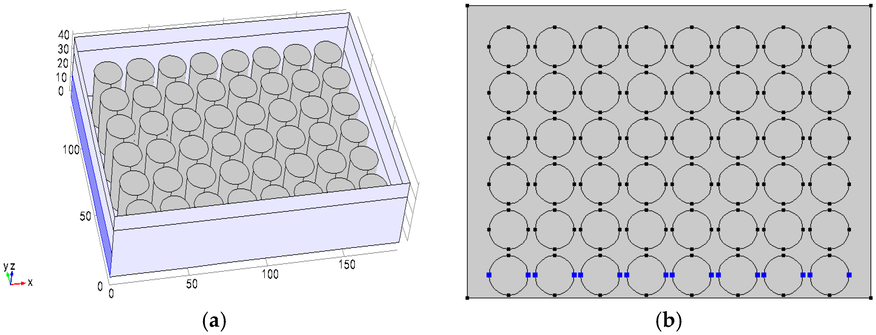
Figure 1a is a quarter of the schematic view for a battery pack with a planar arrangement, where the air inlet area is 20 cm2 (the dark blue part), the outlet area is the same as the inlet area. The spacing between the batteries is 3 mm, and the temperature monitoring points of the structure are distributed as shown in Figure 1b.
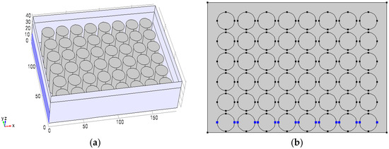
Figure 1.
(a) A quarter of the schematic view for a planar battery arrangement; and (b) distribution of monitoring points.
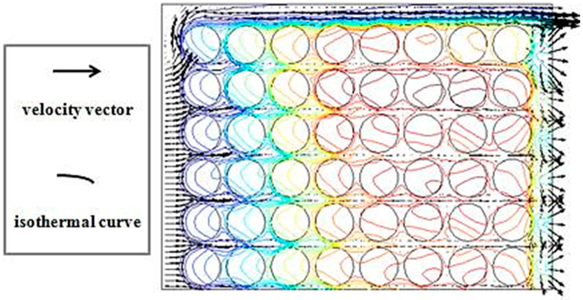
Figure 2 shows the numerical results. The inlet air forms an eddy. The velocity vectors and the isothermal are almost parallel over most of the computational domain, which means that the local concentration gradients and the velocity vectors are nearly vertical to each other, resulting in a large synergy angle between them. According to Figure 3, the air flow passes by the batteries and absorbs the heat from the battery, but the temperature of the air flow rises along the flow path. The temperature rise in the batteries near the air intake is lower than the temperature rise in the back row ones. The air flow rate varies dramatically in the outlet, and easily forms a vortex, going against the flow diffusion.

Figure 2.
Distribution of the velocity vectors and isothermal curves at the rate of 1.0 m/s.
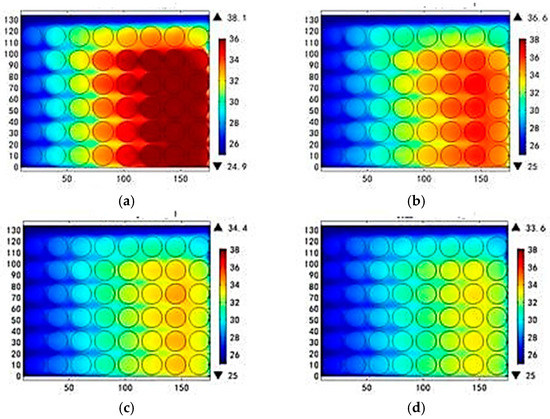
Figure 3.
Battery temperature profiles at different inlet air velocity. (a) 0.7 m/s; (b) 0.8 m/s; (c) 1.0 m/s; (d) 1.1 m/s at 25 °C and 1C discharging rate.
Table 1 shows the temperature distribution of the battery for different flow rates. As the the air inlet velocity increases, the maximum temperature rise is reduced in the same discharging procedure. The highest temperatures are 13.1, 11.6, 9.4 and 8.6 °C when the inlet air velocities are 0.7, 0.8, 1.0, 1.1 m/s, respectively. The maximum temperature difference is 11.3, 10.0, 8.2 and 7.5 °C for the same situation. The increased air inlet velocity promotes the Reynolds number and the surface convective coefficient, which eventually enhances the overall heat extraction rate. The decreasing field synergy angle indicates an increase in the field synergy number and air utilization efficiency.

Table 1.
Temperature rises and temperature differences for different air inlet velocities.
3.2. Different Arrangement Modes
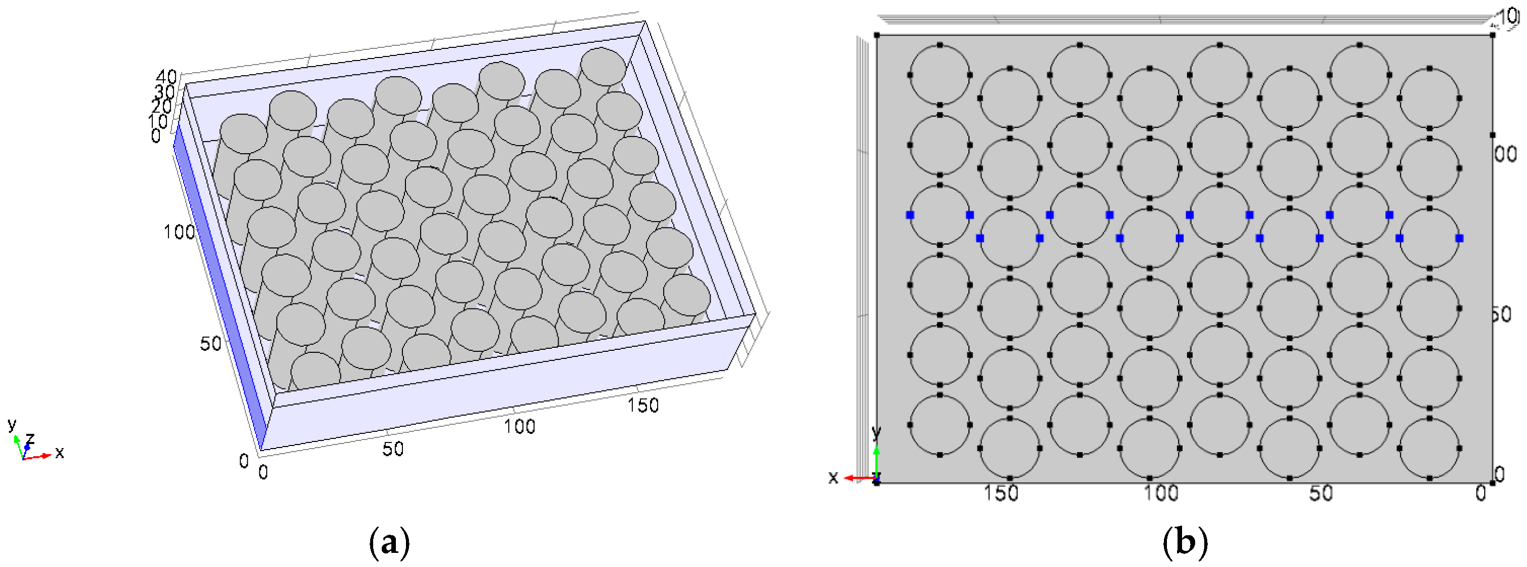
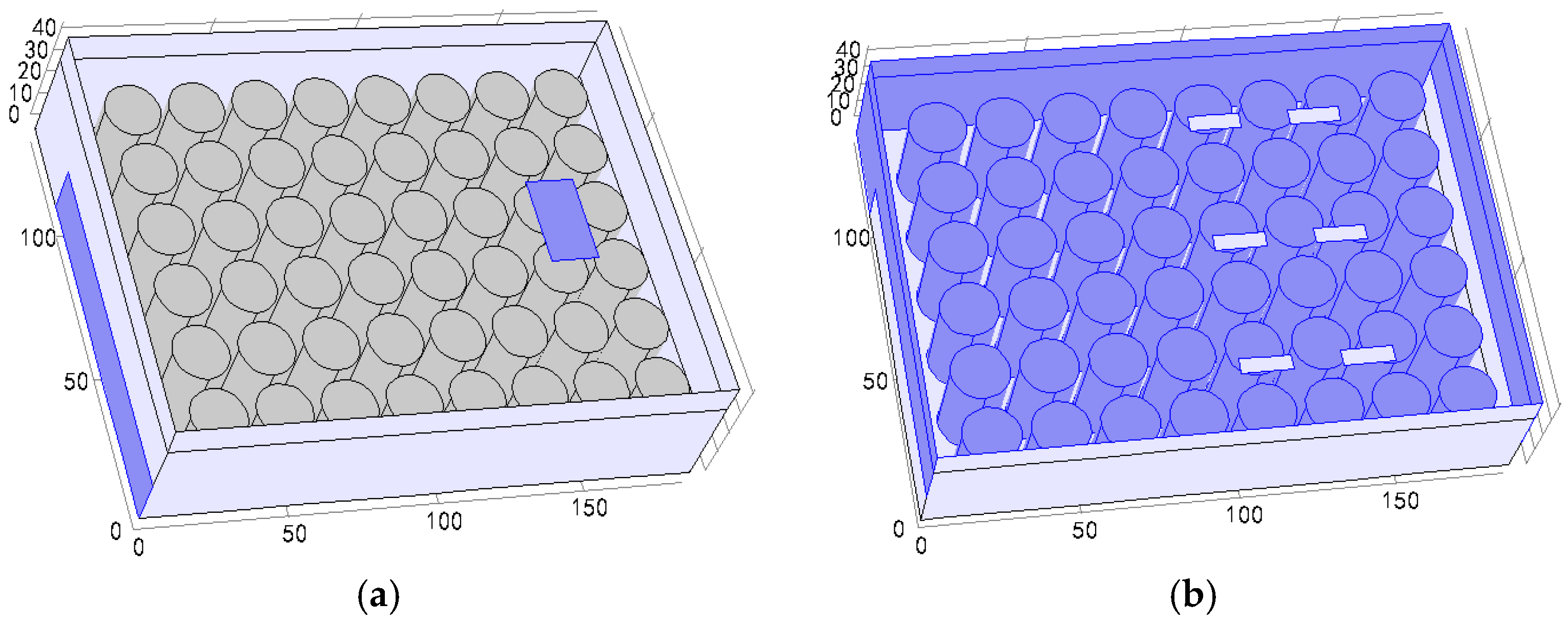
Figure 4a shows that the two adjacent battery modules are placed in a cross arrangement. The air inlet area is 20 cm2 (the dark blue part), outlet area is the same as the inlet area. The spacing distance for the battery is 3 mm, and the structure temperature monitoring points are distributed as shown in Figure 4b.
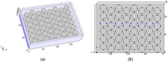
Figure 4.
(a) A quarter of the schematic view for a cross arrangement; and (b) distribution of the monitoring points.
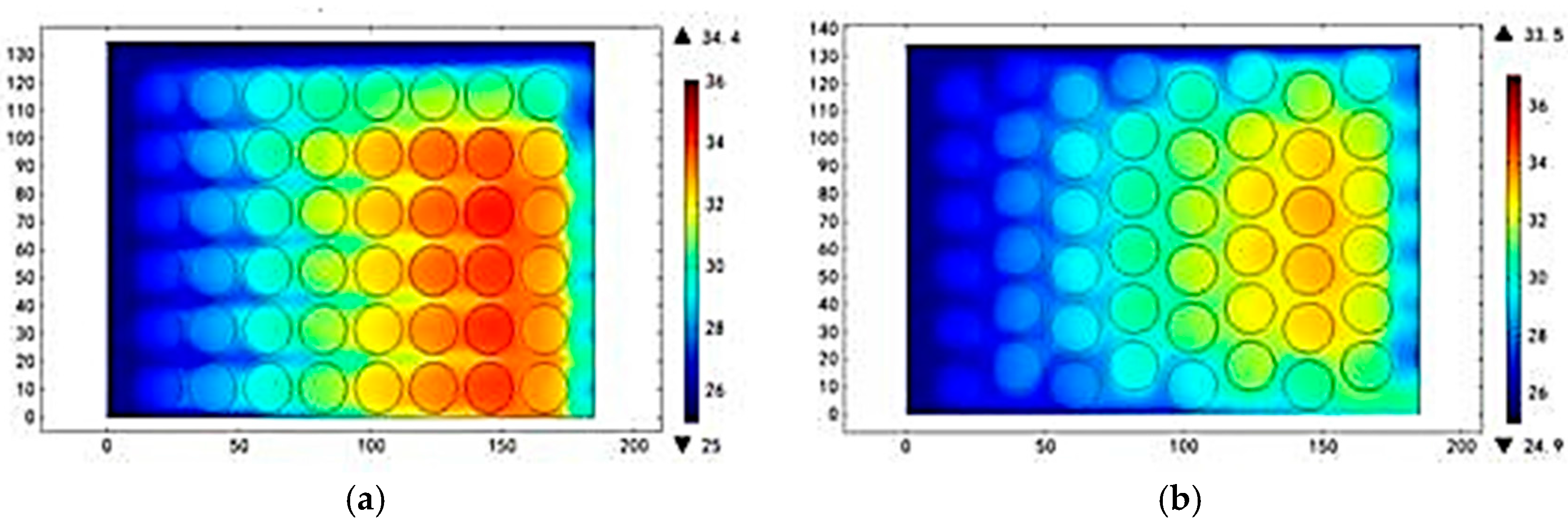
Figure 5 shows the battery temperature profiles for different battery arrangements. It is clearly seen that the battery pack cross arrangement has a better uniformity and a lower temperature. According to Figure 5, the maximum temperature point is in the middle of the profile. The monitoring points were set up as illustrated in Figure 4b.
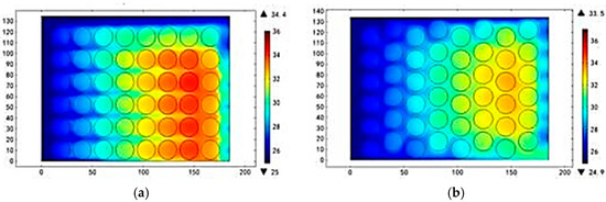
Figure 5.
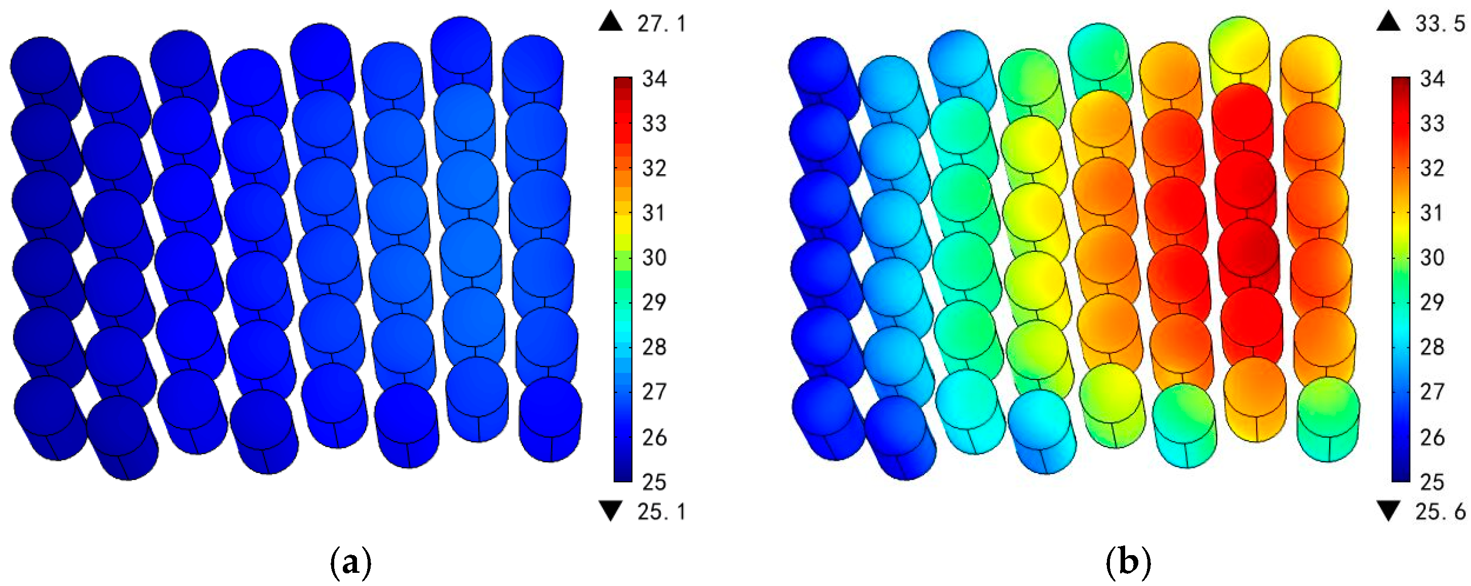
Battery temperature profiles with different battery arrangement at the rate of 1.0 m/s in (a) planar arrangement and (b) cross arrangement at 25 °C and 1C discharging rate.
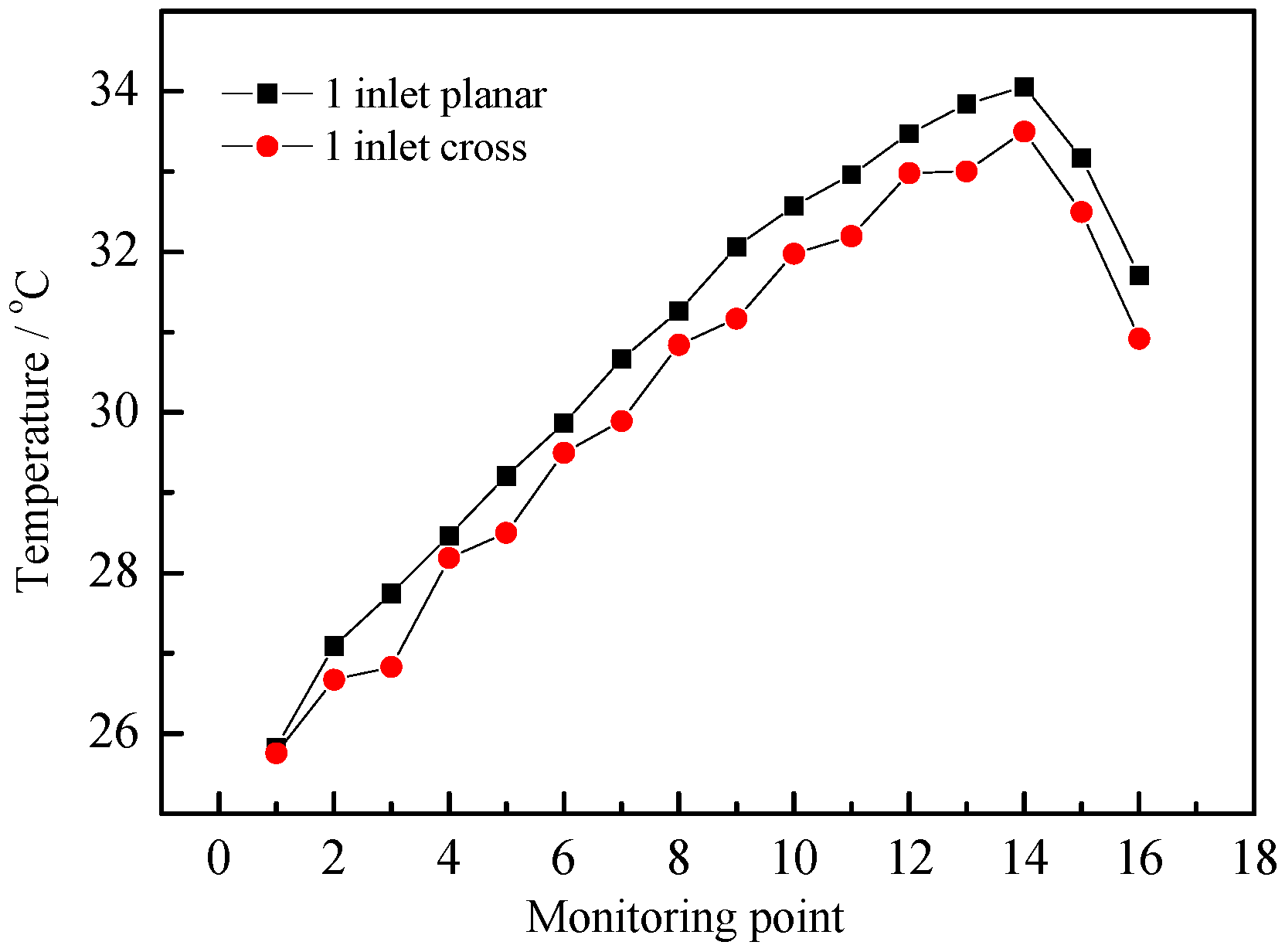
Figure 6 shows a comparison of the temperature rise between the planar and cross arrangement. The air inlet rate was set to 1.0 m/s. The maximum temperature is 33.5 °C and the maximum temperature difference is 7.7 °C in the cross arrangement. The maximum temperature is 34.1 °C and the maximum temperature difference is 8.3 °C in the planar arrangement. The cross arrangement shows better heat dispersion characteristics than the planar arrangement by changing the direction of the air, increasing the disturbance and increasing the convective heat transfer coefficient.
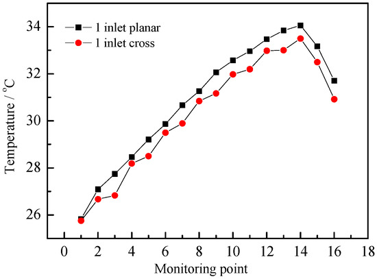
Figure 6.
Comparison of temperature rising with planar and cross arrangement sat the rate of 1.0 m/s at 25 °C and 1C discharging rate.
3.3. Different Inlet Modes
In order to reduce the high temperature appearing in the back row of the battery pack, some holes could be placed near the location of the high temperature. The total inlet area is unchanged (Figure 7).

Figure 7.
A quarter of the schematic view for the battery pack. (a) Two inlets; and (b) seven inlets.
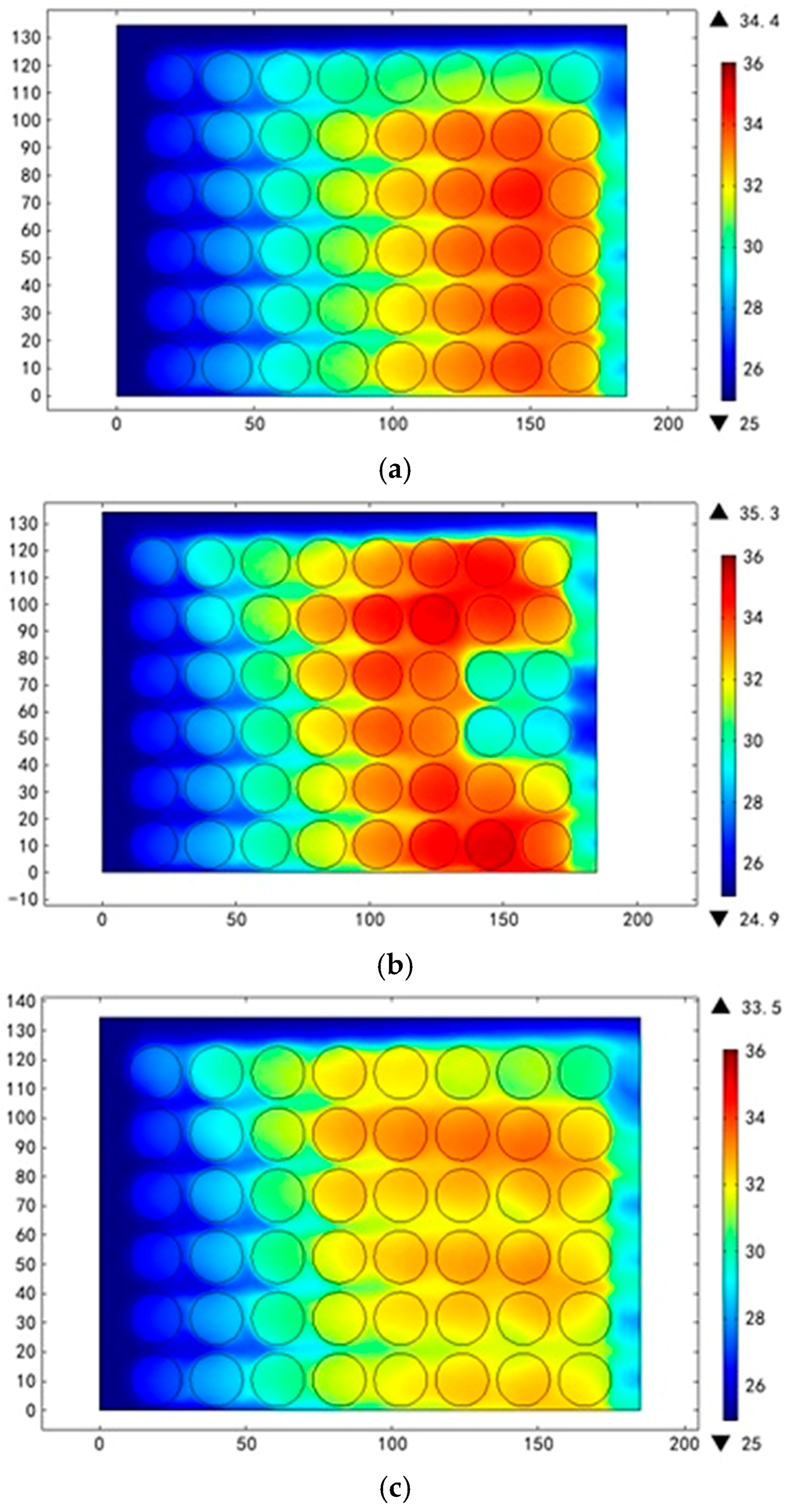
Figure 8 shows that the mode with seven inlets has the best temperature uniformity. The temperature increase is 8.5 °C for a seven inlet mode and 9.4 °C for one inlet mode, a 9.5% reduction. The maximum temperature difference is 7.1 °C in seven inlet mode and 8.5 for inlet mode, a 16.4% reduction.
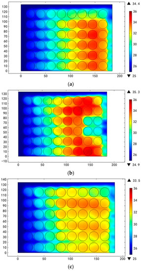
Figure 8.
Battery temperature profiles with different inlet modes at the rate of 1.0 m/s, 25 °C and 1C discharging rate. (a) One inlet; (b) two inlets; and (c) seven inlets.
3.4. Thermal Responses of the Battery Pack under Different Discharge Mechanisms
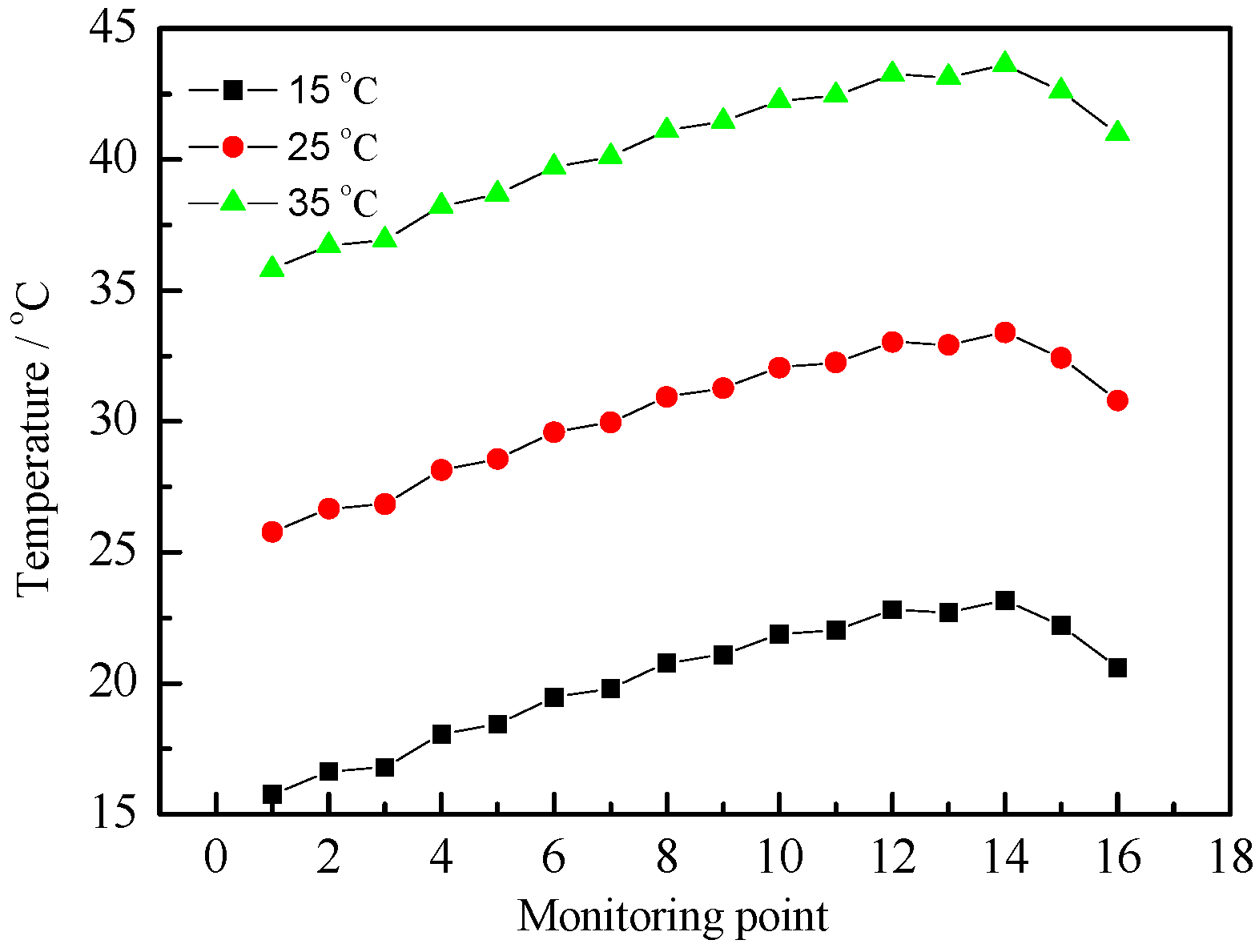
Regarding the impact of air intake temperature, Figure 9 shows a comparison of the temperature rise for different discharge air intake temperatures (15, 25 and 35 5 °C) at a constant inlet velocity (1.0 m/s) and constant discharge rate (1C). The results show that the temperature rises as the number of monitoring points increases. The three curves have a similar trend as the temperature changes. The last two rows near the air outlet have a lower temperature rise than the third row from the back. The highest temperature rises are 9.3, 8.9 and 8.3 °C when the inlet air temperatures are 15, 25 and 35 °C, respectively. The maximum temperature differences are 6.0, 5.6 and 5.0 °C under the same situation. The higher inlet temperature may cause a slower temperature rise speed and a slower temperature gradient, resulting in the decreasing field synergy angle shows a rising trend (Table 2).
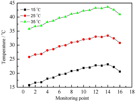
Figure 9.
Comparison of the temperature rise for different discharge air intake temperatures (15, 25 and 35 °C) at a constant inlet velocity (1.0 m/s) and 1C discharging rate.
Table 2.
Temperature rise and temperature differences for different air inlet temperatures.
A larger discharge rate is generally associated with a higher heat production rate. Figure 10 shows a comparison of the battery temperature profiles with different discharging rates at constant temperature (25 °C). The results show that battery temperature is increasing significantly at a higher discharging rate. The highest temperature rise is 2.1 and 8.5 °C, when the discharging rates are 0.5C and 1C, respectively. The maximum temperature differences are 1.2 and 7.6 °C in the same situation (Table 3). A higher discharging rate is caused by a higher resistance and polarization heat production rate.
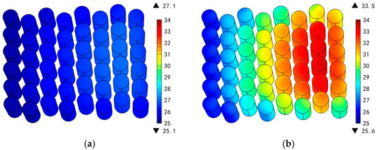
Figure 10.
Battery temperature profiles with discharging rates of (a) 0.5C and (b) 1C at 25 °C.
Table 3.
Temperature rises and temperature differences at different discharging rates.
4. Conclusions
The field synergy principle has been applied to analyze heat transfer in order to improve the overall temperature distribution of electric vehicle battery pack systems. In air cooling processes, the overall system cooling capability can be enhanced by increasing the air inlet velocity or by enlarging the synergy between the velocity vectors and the temperature gradients. However, although increases of the air inlet velocity were found to improve the cooling rates, the inlet velocity increases also reduced the field synergy number which leads to a reduction in the air utilization efficiency. Different arrangements of the batteries were compared as well. The cross arrangement was found to have a better heat transfer ability while increasing the disturbance. Moreover, different discharge characteristics like discharging rate and initial air temperature have also been discussed for getting better temperature uniformity. Although the optimal flow field obtained from the heat transfer field synergy equation may differ in practical flow fields in some aspects, the optimized velocity field still provides guidelines to guide flow fields designs that will improve the heat transfer in practical applications.
Acknowledgments
This work was supported by the National Natural Science Foundation of China (No. 51276022) and (No. 51507012).
Author Contributions
Hongwen He and Weiwei Huo contributed to the conception of the study; Weiwei Huo and Hui Jia established the model; Hongwen He and Hui Jia performed the data analyses and wrote the manuscript; Fengchun Sun and Weiwei Huo helped perform the analysis with constructive discussions.
Conflicts of Interest
The authors declare no conflict of interest.
Nomenclature
| cp | Specific heat capacity, J·kg−1·K−1 |
| k | Thermal conductivity, W·m−1·K−1 |
| x, y | Cartesian coordinates, m |
| u, v | Velocity component in x-, y-, m·s−1 |
| Thermal boundary layer thickness, m | |
| T | Temperature, K |
| H | Characteristic length |
| U | Velocity vector |
| h | Convective heat-transfer coefficient |
| Flow domain | |
| l | Flow domain boundary |
| ρ | Air density, kg·m−3 |
| v | Coefficient of viscosity |
Subscripts
| w | Wall |
| m | Characteristic |
| avg | Average |
References
- Kwon, K.H.; Shin, C.B.; Kang, T.H.; Kim, C.S. A two-dimensional modeling of a lithium-polymer battery. J. Power Sources 2006, 163, 151–157. [Google Scholar] [CrossRef]
- Guo, M.; White, R.E. A distributed thermal model for a Li-ion electrode plate pair. J. Power Sources 2013, 221, 334–344. [Google Scholar] [CrossRef]
- Xiong, R.; He, H.W.; Sun, F.C.; Liu, X.; Liu, Z. Model-based state of charge and peak power capability joint estimation of lithium-ion battery in plug-in hybrid electric vehicles. J. Power Sources 2013, 229, 159–169. [Google Scholar] [CrossRef]
- Chen, Z.; Xiong, R.; Tian, J. Model-based fault diagnosis approach on external short circuit of lithium-ion battery used in electric vehicles. Appl. Energy 2016, 184, 365–374. [Google Scholar] [CrossRef]
- Srinivasan, V.; Wang, C.Y. Analysis of electrochemical and thermal behavior of Li-ion cells. J. Electrochem. Soc. 2003, 150, A98–A106. [Google Scholar] [CrossRef]
- Kim, G.H.; Pesaran, A.; Spotnitz, R. A three-dimensional thermal abuse model for lithium-ion cells. J. Power Sources 2007, 170, 476–489. [Google Scholar] [CrossRef]
- Chen, Y.; Evans, J.W. Thermal analysis of lithium polymer electrolyte batteries by a two dimensional model—Thermal behavior and design optimization. Electrochim. Acta 1994, 39, 517–526. [Google Scholar] [CrossRef]
- Forgez, C.; Friedrich, G.; Morcrette, M.; Delacourt, C. Thermal modeling of a cylindrical LiFePO4/graphite lithium-ion battery. J. Power Sources 2010, 195, 2961–2968. [Google Scholar] [CrossRef]
- Smith, K.; Kim, G.H.; Darcy, E.; Pesaran, A. Thermal/electrical modeling for abuse-tolerant design of lithium ion modules. Int. J. Energy Res. 2010, 34, 204–215. [Google Scholar] [CrossRef]
- Mills, A.; Al-Hallaj, S. Simulation of passive thermal management system for lithium-ion battery packs. J. Power Sources 2005, 141, 307–315. [Google Scholar] [CrossRef]
- Sabbah, R.; Kizilel, R.; Selman, J.R.; Al-Hallaj, S. Active (air-cooled) vs. passive (phase change material) thermal management of high power lithium-ion packs: Limitation of temperature rise and uniformity of temperature distribution. J. Power Sources 2008, 182, 630–638. [Google Scholar] [CrossRef]
- Kizilel, R.; Sabbah, R.; Selman, J.R.; Al-Hallaj, S. An alternative cooling system to enhance the safety of Li-ion battery packs. J. Power Sources 2009, 194, 1105–1112. [Google Scholar] [CrossRef]
- Guo, Z.Y.; Li, D.Y.; Wang, B.X. A novel concept for convective heat transfer enhancement. Int. J. Heat Mass Transf. 1998, 41, 2221–2225. [Google Scholar] [CrossRef]
- Tao, W.Q.; Guo, Z.Y.; Wang, B.X. Field synergy principle for enhancing convective heat transfer––Its extension and numerical verifications. Int. J. Heat Mass Transf. 2002, 45, 3849–3856. [Google Scholar] [CrossRef]
- Tao, W.Q.; He, Y.L.; Wang, Q.W.; Qu, Z.G.; Song, F.Q. A unified analysis on enhancing single phase convective heat transfer with field synergy principle. Int. J. Heat Mass Transf. 2002, 45, 4871–4879. [Google Scholar] [CrossRef]
- Cheng, Y.P.; Qu, Z.G.; Tao, W.Q.; He, Y.L. Numericaldesign ofefficientslottedfinsurfacebasedonthe field synergy principle. Numer. Heat Transf. Part A Appl. 2004, 45, 517–538. [Google Scholar] [CrossRef]
- Tao, W.Q.; He, Y.L.; Qu, Z.; Cheng, Y.P. Applications of the field synergy principle in developing new type heat transfer enhanced surfaces. J. Enhanc. Heat Transf. 2004, 11, 435–452. [Google Scholar] [CrossRef]
- Yu, H.; Wen, J.; Xu, G.; Li, H. Theoretically and numerically investigation about the novel evaluating standard for convective heat transfer enhancement based on the entransy theory. Int. J. Heat Mass Transf. 2016, 98, 183–192. [Google Scholar] [CrossRef]
- Wang, J.; Liu, Z.; Yuan, F.; Liu, W.; Chen, G. Convective heat transfer optimization in a circular tube based on local exergy destruction minimization. Int. J. Heat Mass Transf. 2015, 90, 49–57. [Google Scholar] [CrossRef]
- Fernández-Gutiérrez, A.; González-Prieto, I.; Parras, L.; Cejudo-López, J.M.; del Pino, C. Experimental and numerical study of a small-scale and low-velocity indoor diffuser coupled with radiant floor cooling. Int. J. Heat Mass Transf. 2015, 87, 71–78. [Google Scholar] [CrossRef]
- Jia, H.; Liu, Z.C.; Liu, W.; Nakayama, A. Convective heat transfer optimization based on minimum entransy dissipation in the circular tube. Int. J. Heat Mass Transf. 2014, 73, 124–129. [Google Scholar] [CrossRef]
- Jia, H.; Liu, W.; Liu, Z. Enhancing convective heat transfer based on minimum power consumption principle. Chem. Eng. Sci. 2012, 69, 225–230. [Google Scholar] [CrossRef]
- Xie, Z.; Chen, L.; Sun, F.C. Constructal optimization of a vertical insulating wall based on a complex objective combining heat flow and strength. Sci. China Technol. Sci. 2010, 53, 2278–2290. [Google Scholar] [CrossRef]
- Chen, Q.; Wang, M.; Guo, Z.Y. Field synergy principle for energy conservation analysis and application. Adv. Mech. Eng. 2010, 2, 129313. [Google Scholar] [CrossRef]
- Chen, Q.; Ren, J.; Guo, Z. The extremum principle of mass entransy dissipation and its application to decontamination ventilation designs in space station cabins. Chin. Sci. Bull. 2009, 54, 2862–2870. [Google Scholar] [CrossRef]
- Mo, J.; Zhang, Y.; Yang, R. Novel insight into VOC removal performance of photocatalytic oxidation reactors. Indoor Air 2005, 15, 291–300. [Google Scholar] [CrossRef] [PubMed]
- Huang, Y.Q. The Flow and Heat Transfer Coupling Analysis and Construction Modification of Vehicular Cooling Models Based on Field Synergy Principle; Zhejiang University: Hangzhou, China, 2010. [Google Scholar]
- Jiang, Y. Simulation and Analysis of Heat Transfer Performance of the Slotted Circular Fin Based on Field Synergy Principle; Harbin Engineering University: Harbin, China, 2011. [Google Scholar]
- Yang, M.; Zhao, M.; Zhang, L.X. Field synergy principle and stability of heat convection. J. Eng. Thermophys. 2002, 23, 73–76. [Google Scholar]
- Huo, W.W.; He, H.W.; Sun, F.C. Electrochemical-thermal modeling for a ternary lithium ion battery during discharging and driving cycle testing. RSC Adv. 2015, 5, 57599–57607. [Google Scholar] [CrossRef]

© 2017 by the authors; licensee MDPI, Basel, Switzerland. This article is an open access article distributed under the terms and conditions of the Creative Commons Attribution (CC-BY) license (http://creativecommons.org/licenses/by/4.0/).