Abstract
This paper studies the non-uniform air-gap caused by stator and rotor deformations, together with its effects on the spatial and temporal spectrum of the radial magnetic force density in an interior permanent magnet synchronous motor (IPMSM). According to the mathematical model of the deformed air-gap length, the superposition method is adopted to derive the air-gap permeance. Then, the formulas of the magnetic flux field and radial force density of the IPMSM considering air-gap deformation are obtained. Considering the stator oval deformation and the rotor centrifugal distortion in the electromagnetic finite element models (FEMs), the finite element analysis (FEA) and experiments of the investigated IPMSM are carried out to verify the results obtained by the theoretical analysis at different operations. Finally, the mathematical correlation between air-gap deformation and electromagnetic vibration is obtained. The result is helpful in solving problems of mutual influence between electromagnetic and mechanical characteristics during the optimization design of IPMSM.
1. Introduction
Interior permanent magnet synchronous motors (IPMSMs) have been widely applied in electrical vehicle systems due to the advantages of high power density, high torque density, high efficiency, low torque ripple, and so on [1,2,3,4,5,6]. The vibration in the permanent magnet synchronous motor (PMSM) has been a significant topic for the last couple of decades [7,8,9]. Usually for small and medium-sized PMSMs, electromagnetic vibration is the major cause of the overall vibration, which results from the radial magnetic forces acting on the inner surface of stator [10]. The radial magnetic force is directly correlated with the flux density in the air-gap, so that the uniformity of air-gap of an IPMSM is very important for its vibration.
However, for the PMSM applied in an in-wheel motor driving system, the manufacture tolerance, the assembly quality, the demagnetization faults [11], the operating conditions and the performing environments can all lead to stator and rotor core deformations and eccentricities, which are called air-gap deformation. In order to reduce the vibration of the IPMSM, the mathematical correlation between air-gap deformation and electromagnetic vibration should be analyzed.
The eccentricities in IPMSMs vary both in radial and axial directions [12]. The former is much more common and includes three types: static, dynamic, and mixed eccentricity [13]. It has been concluded that stator current is the most commonly monitored signal for fault diagnosis because it is easily monitored without sensors [14]. Ebrahimi, B. M. et al. have introduced the new index based on the decomposition wavelet transform of the stator current to analyze their relations to static and dynamic eccentricity fault and identify the eccentricity type and estimating its degree [15]. Carlos López-Torres et al. have analyzed the spectral content of the stator currents and the zero-sequence voltage component under the effects of air-gap asymmetries in five-phase ferrite-permanent magnet (PM) assisted synchronous reluctance machines [16].
Meanwhile, many analytical methods and models have been developed to study the influences of air-gap eccentricities on the air-gap magnetic field distributions. L. Yanxin proposes an analytical method that combines the superposition and the subdomain methods to predict the air-gap magnetic field distribution in permanent magnet machines with rotor eccentricity [17]. Babaei, M. presents a new detailed analytical model of a salient-pole synchronous generator under dynamic eccentricity considering the effects of magnetic saturation, rotor pole shoe saliency, and space distribution of stator phases and rotor winding [18]. By analyzing the magnetic field distribution under the air-gap eccentricity, the unbalanced magnetic pulls can be derived [19,20]. These together have a great impact on the electromagnetic vibration in the IPMSM [21,22].
On the whole, the studies on the effects of air-gap eccentricities in IPMSMs are comprehensive and mature. As another major cause of the air-gap deformation, the effect of stator and rotor core deformation also has an important research value. Thus, this paper mainly focuses on the non-uniform air-gap caused by stator and rotor core deformations, together with its effects on the spatial and temporal spectrum of the radial magnetic force in an IPMSM. The motor under investigation in this paper is a 90 kW permanent magnet synchronous in-wheel motors (PMSIWM), and the cross sectional view of the interior permanent magnet (IPM) rotor is shown in Figure 1. The main parameters of the machine are given in Table 1.
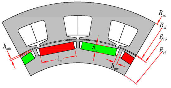
Figure 1.
Cross-sectional view of the PMSIWM with IPM rotor.

Table 1.
Main parameters of interior permanent magnet synchronous motors (IPMSMs).
The stator core of the IPMSM used in the in-wheel motor system may deform because of the impacting loads from the excitations of different road surfaces [23,24,25]. The relationship between the magnitude of the deformation and the impacting loads will be discussed in the further investigations. Moreover, due to the radial vibrations at the second harmonic frequency and the slot harmonics effect on the magnetic pull [26], the stator will be dragged into an elliptical form after a long period of operation. Tan-Kim has analyzed the stator deformations caused by the manufacturing process of a claw-pole alternator and investigated their effects on the magnetic forces and the subsequent vibrations. The stator deformations are found to significantly increase the vibration level of particular orders [27]. Q. Lv et al. have modeled a squirrel cage induction motor with an oval stator under different eccentricity conditions and compared the performances of the motors with a circinal stator and oval stator using FEM. It has been found that the rotor eccentricity and the stator ovality can be detected by the stator currents spectra and electromagnetic torque [28].
The rotor deformation can be mainly divided into two types: thermal deformation caused by high temperature, and pole shoe deformation caused by high centrifugal force. The combined effects of these two factors are very complex. To simplify the analytical process, the rotor deformation in this paper is focused on the centrifugal distortion of pole shoe. In fact, the rotor deformation is similar to the initiative modification of the pole shoe shape in an IPMSM. Both need to derive their mathematical correlation between the outer shape of the rotor and the air-gap magnetic field. Through the modification of the pole shoe shape, the distribution and the harmonics of the radial magnetic force density will be affected, and the dominant order of the radial force density can be reduced selectively [29]. However, unlike the initiative modification of the pole shoe shape, the rotor deformation has a high degree of complexity and uncertainty. The structural types and geometrical parameters of the interior rotors, such as the thickness of magnetic bridge, the thickness of the magnetic rib, and the angle between two PMs in a V-shaped type rotor, can all affect the centrifugal distortion of the pole shoe.
Taking this all into account, the inner surface shape of the deformed stator is supposed to be an ellipse in this paper; the ovality of the deformed stator is defined as the ratio of the amount of deformation to the original air-gap length. In addition, the distribution of rotor centrifugal distortion under a single pole is similar to one part of an eccentric circle, of which the eccentricity is the maximum deformation of the pole shoe. Therefore, the rotor core deformation studied in this paper can be regarded as a special dynamic eccentricity, which is synthesized by the eccentric effect of each pole shoe.
In Section 2, according to the proposed mathematical model of the deformed air-gap length, the superposition method is adopted to derive the air-gap permeance. Then, the formulas of magnetic flux field and radial force density of the IPMSM considering air-gap deformation are obtained. In Section 3 and Section 4, the stator oval deformation and the rotor centrifugal distortion are included in the electromagnetic finite element models (FEMs). The finite element analysis (FEA) and experiments of the investigated IPMSM are carried out to verify the results obtained by the theoretical analysis.
2. Theoretical Analysis of Radial Magnetic Force Density Considering Air-Gap Deformation
In this section, the variation of radial air-gap length and the corresponding air-gap relative permeance can be obtained by analyzing the mathematical model of the IPMSM considering stator oval deformation and rotor centrifugal distortion. As is well known, the air-gap magnetic flux density is equal to the magnetomotive force (MMF) multiplied by the air-gap relative permeance. Since the MMF of the motor can be divided into stator MMF and rotor MMF, the air-gap magnetic flux density under air-gap deformation is also divided into two parts to analyze the different effects of no-load and high-speed load conditions. Finally, the corresponding radial magnetic force density can be obtained according to the method of Maxwell stress tensor. The formulas in this section are derived in order to analyze the additional spatial and temporal contents of the air-gap magnetic field and radial force density under different air-gap deformations.
2.1. Air-Gap Permeance
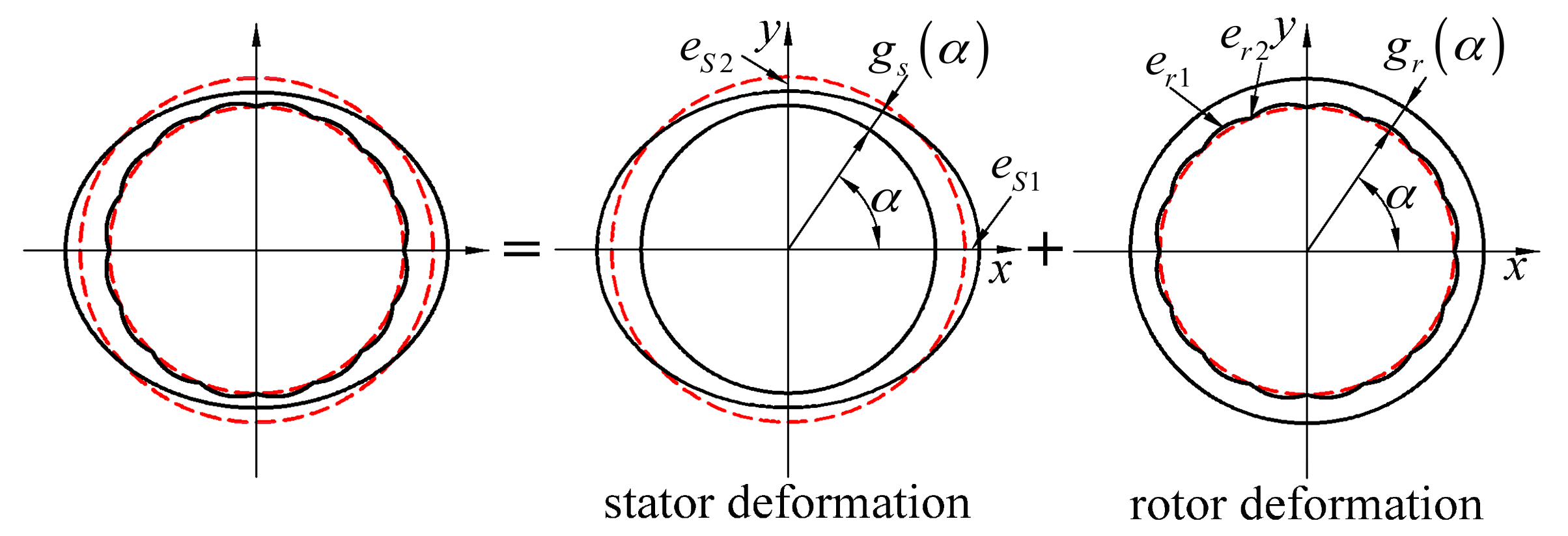
As is well known, a precise knowledge of the air-gap length plays a significant role in the formulation of the magnetic field. However, the air-gap length considering stator and rotor deformation is complex during the operation of the motor. It is difficult to describe the air-gap permeance with a single expression accurately. Therefore, in the first step of the analyzing process, the superposition method is proposed to derive the air-gap permeance of the IPMSM considering stator and rotor deformation, which is shown in Figure 2.
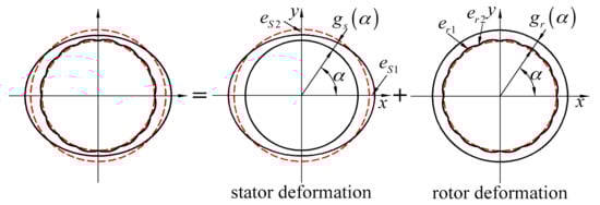
Figure 2.
The analytical model of the IPMSM considering stator and rotor deformations.
To simplify the calculation, the following assumptions and conditions are employed:
- (1)
- The air-gap of the IPMSM is assumed to be smooth and uniform, with magnetic saturation and slot opening being neglected;
- (2)
- The radial air-gap length is much smaller than the stator and rotor radii;
- (3)
- The air-gap deformation is so small that the value of stator deformation at the maximum air-gap length is assumed to be the same as that at minimum air-gap length;
- (4)
- The three-phase IPMSM is fed with a sinusoidal and balanced current system.
Therefore, the average air-gap length in a healthy IPMSM is written as follows:
The relative permeance of the smooth air-gap is
According to the analysis and assumptions above, the radial air-gap length of the stator oval deformation varying around the magnetic circuit periphery can be expressed as
The corresponding relative deformations are defined as
Similarly, the variation of radial air-gap length of the rotor centrifugal distortion around the magnetic circuit periphery and with time is
Thus, the relative permeance of the deformed air-gap is
For stator deformation,
For rotor deformation,
2.2. Magnetic Flux Density
The space and time distribution of the stator magnetomotive force (MMF) and rotor MMF of an IPMSM fed with sinusoidal and balanced current system can be expressed by the following equations:
The instantaneous value of the radial component magnetic flux density distribution in an IPMSM with a non-uniform air gap can be described as follows:
For the stator deformation,
For the rotor deformation,
According to Equations (12)–(15), the additional contents of magnetic flux density in the IPMSM considering stator oval deformation and rotor centrifugal distortion at different operating conditions are summarized in Table 2.
Table 2.
Additional contents of magnetic flux density in the IPMSM.
2.3. Radial Magnetic Force Density
According to the method of Maxwell stress tensor, the radial magnetic force density waveform at any point of the air-gap can be expressed as:
The radial force waves can be divided into three groups:
- (1)
- the product (b1(α,t))2 of the stator harmonics of the same number v;
- (2)
- the product (b2(α,t))2 of the rotor harmonics of the same number μ;
- (3)
- the product 2b1(α,t)b2(α,t) of the stator v and rotor μ harmonics.
In fact, the fundamental magnetic field plays a dominant role in the calculation of radial magnetic force density. Thus, we let v = 1 and μ = 1. For the stator deformation,
For the rotor deformation,
Similarly, according to Equations (17)–(22), Table 3 shows the additional contents of radial force density in the IPMSM considering stator oval deformation and rotor centrifugal distortion. The constant terms in these equations, which do not vary with the time, make no contribution to vibration and can be neglected.
Table 3.
Additional contents of radial magnetic force density in the IPMSM.
3. FEA of Air-Gap Deformation Effects
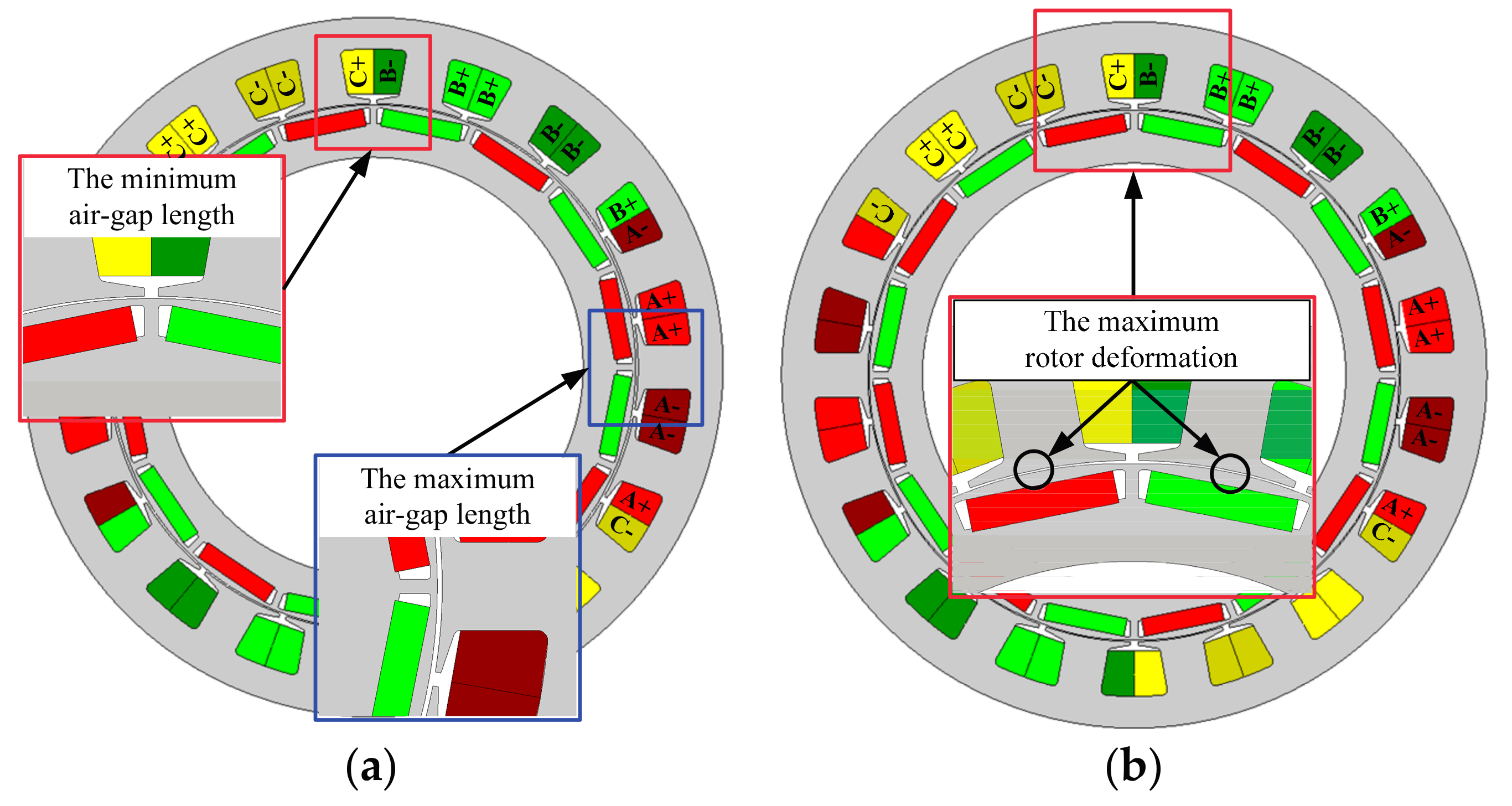
FEM is a powerful numerical method which takes into account rotor saliency, stator slots, and magnetic saturation in the modeling and simulation process of healthy and faulty IPMSMs. Therefore, the electromagnetic model of the IPMSM considering the variation of the value of stator and rotor deformations is built with the software FLUX 12.2 (Altair, Antony, France) for transient magnetic calculation, as shown in Figure 3. In order to analyze the spatial harmonics of the radial air-gap flux density and radial force density conveniently and accurately, the whole finite element model of motor is adopted. The infinite box around the outer face of stator is used to define the boundary condition.
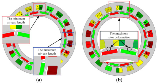
Figure 3.
Electromagnetic FEMs of the IPMSM with air-gap deformation. (a) Stator oval deformation; (b) Rotor centrifugal distortion.
In this section, the radial components of the air-gap flux field at no-load condition (4000 rpm, 0 N·m) and at high-speed load condition (4000 rpm, 135 N·m) are computed and then employed to calculate radial force density. Through the harmonic analysis of flux field and radial force density, the influence of stator and rotor deformations is investigated.
3.1. Effects of Stator Deformation
3.1.1. No-Load Condition
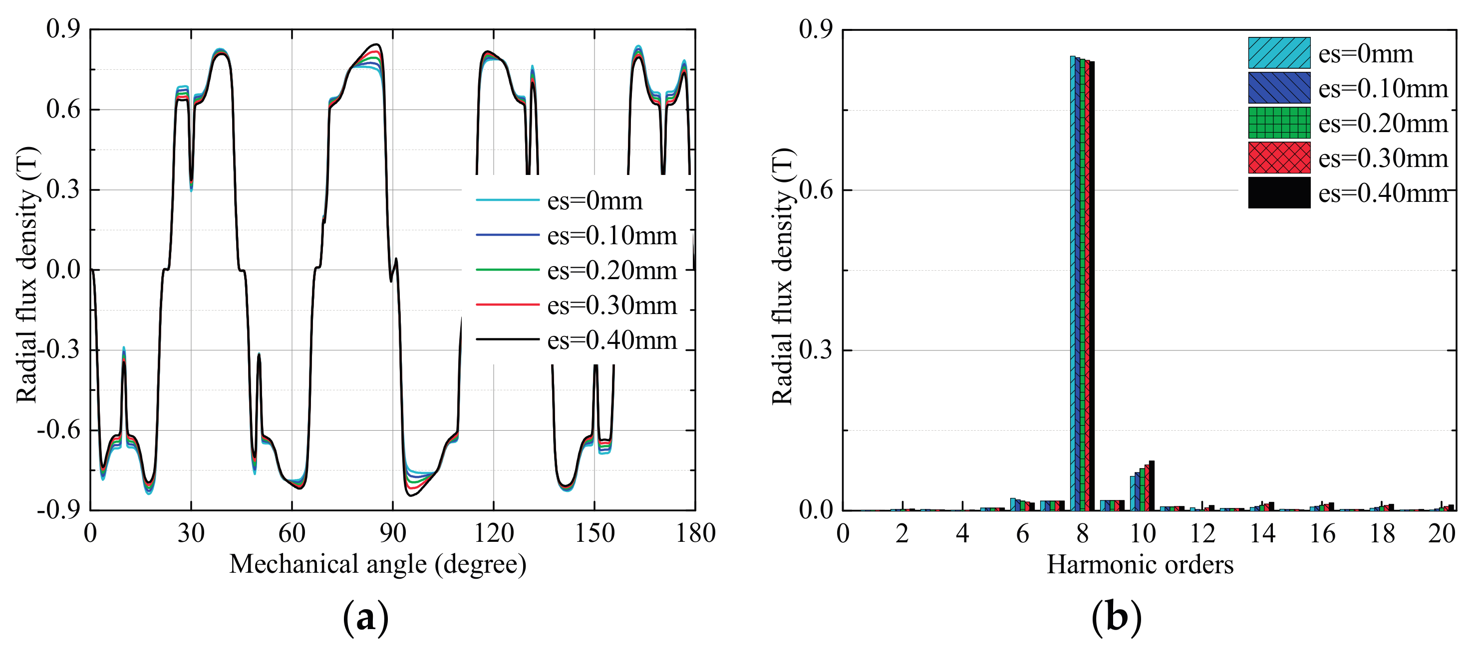
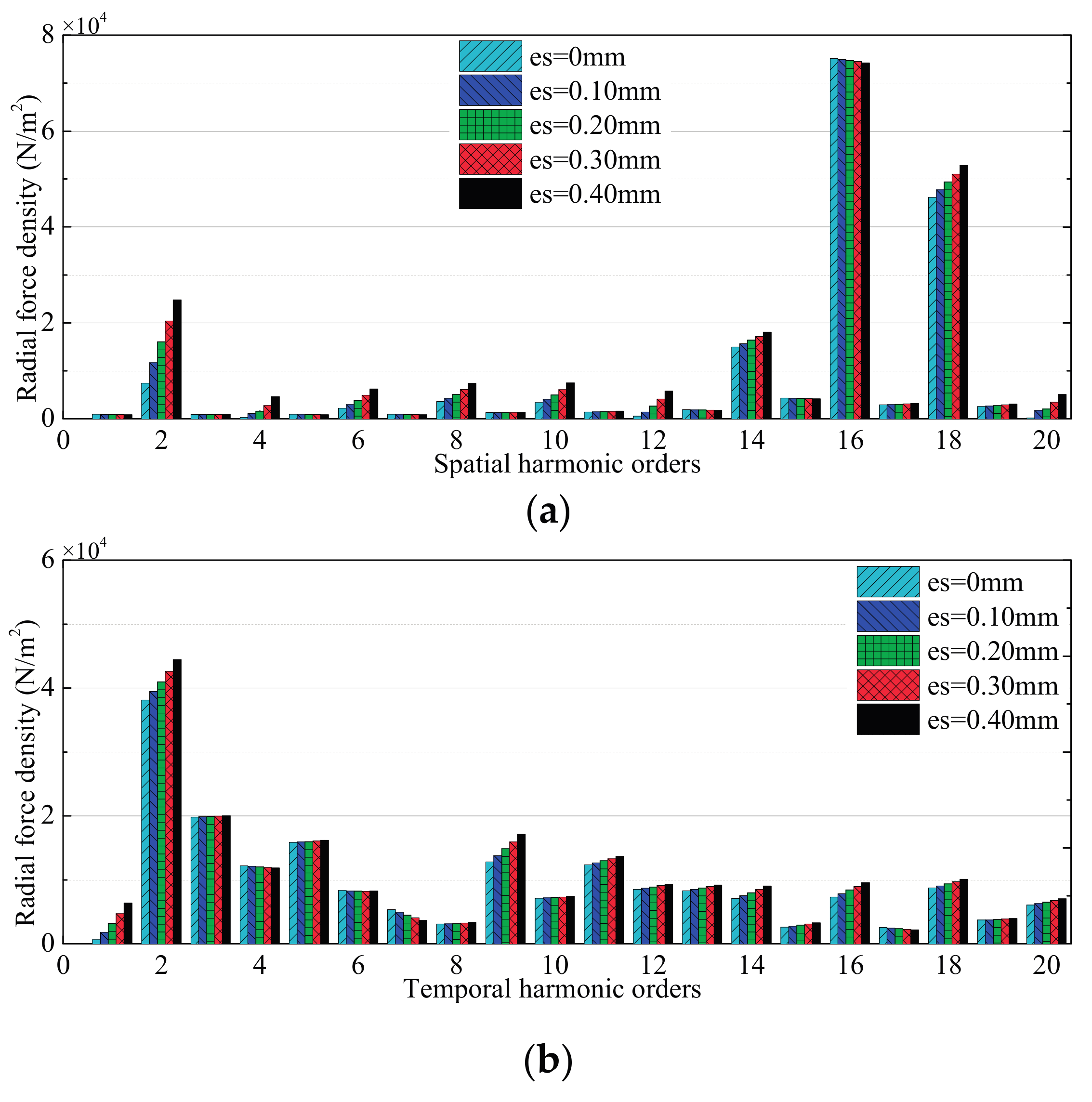
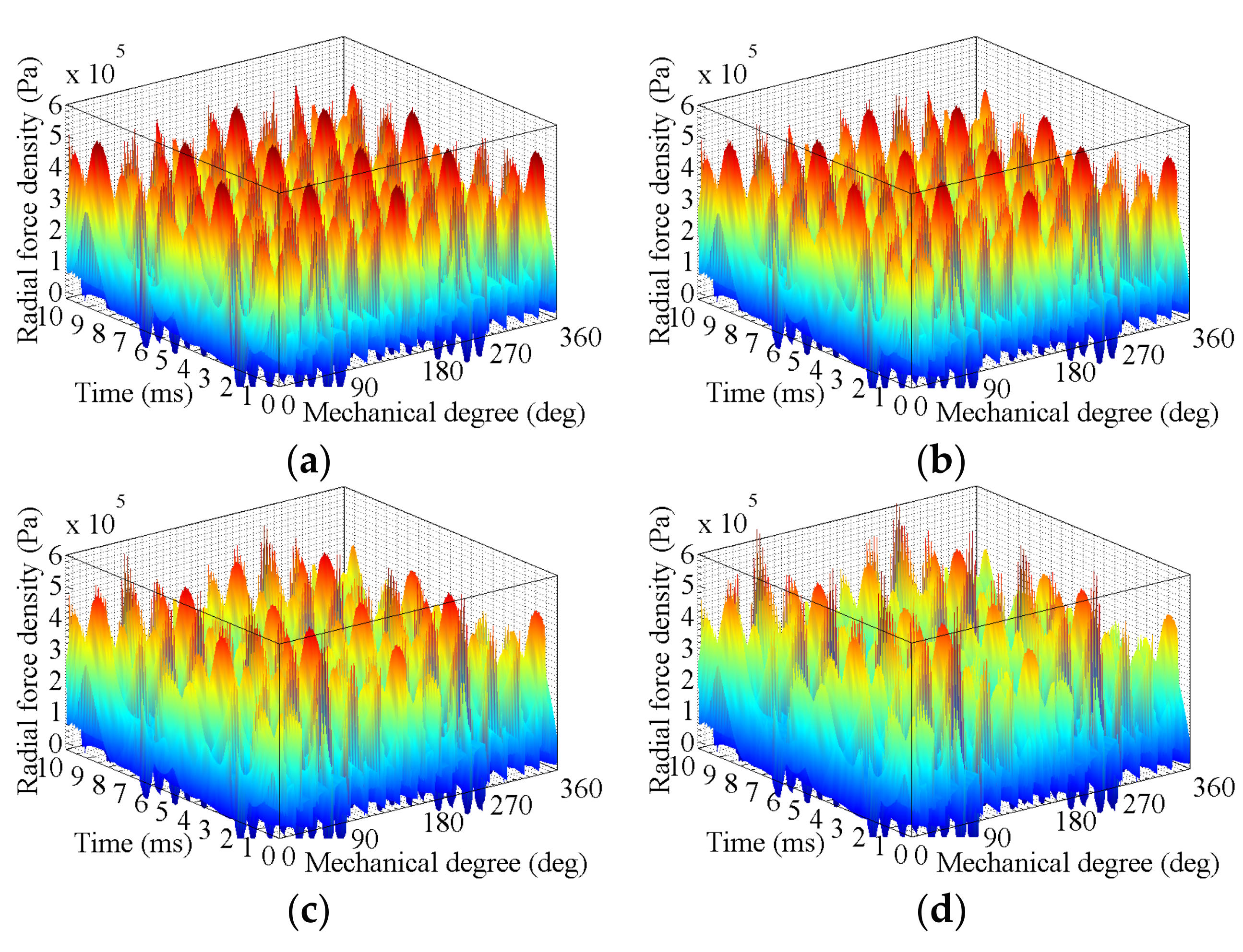
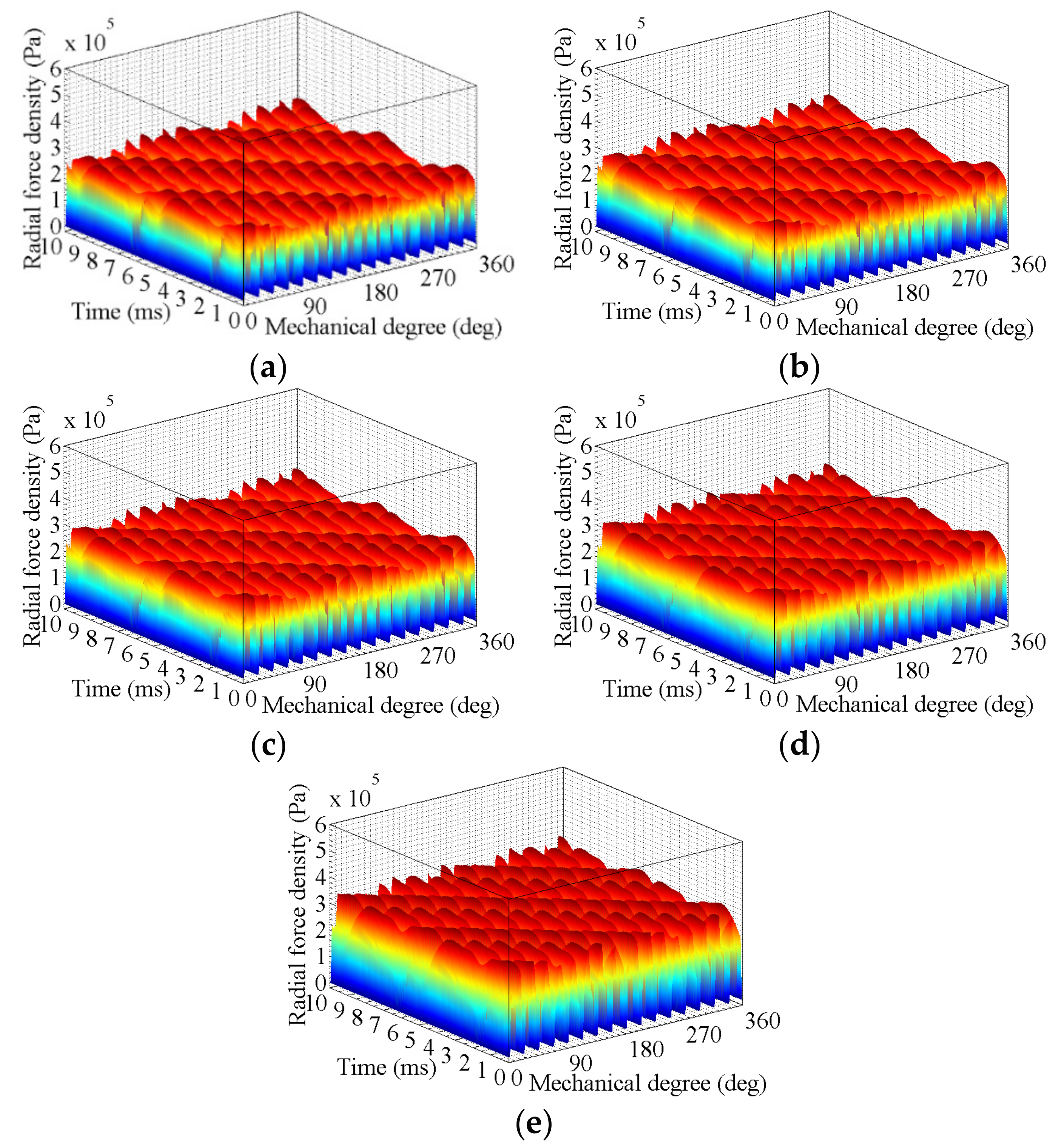
Figure 4 shows the radial component of air-gap flux density distribution and the corresponding harmonic orders at the no-load condition, which varies with the value of the stator oval deformation. According to Equation (16), the corresponding radial force density can be calculated. The three-dimensional waveform of radial magnetic force density and its spatial and temporal harmonic analysis are shown in Figure 5 and Figure 6, respectively.

Figure 4.
Analysis of the radial component of magnetic flux density in the IPMSM with stator deformation at no-load condition. (a) Distribution curves; (b) Harmonic contents.
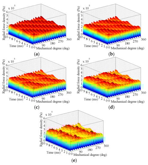
Figure 5.
Radial force density in the IPMSM with stator deformation at no-load condition. (a) es = 0 mm; (b) es = 0.1 mm; (c) es = 0.2 mm; (d) es = 0.3 mm; (e) es = 0.4 mm.
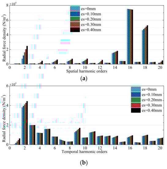
Figure 6.
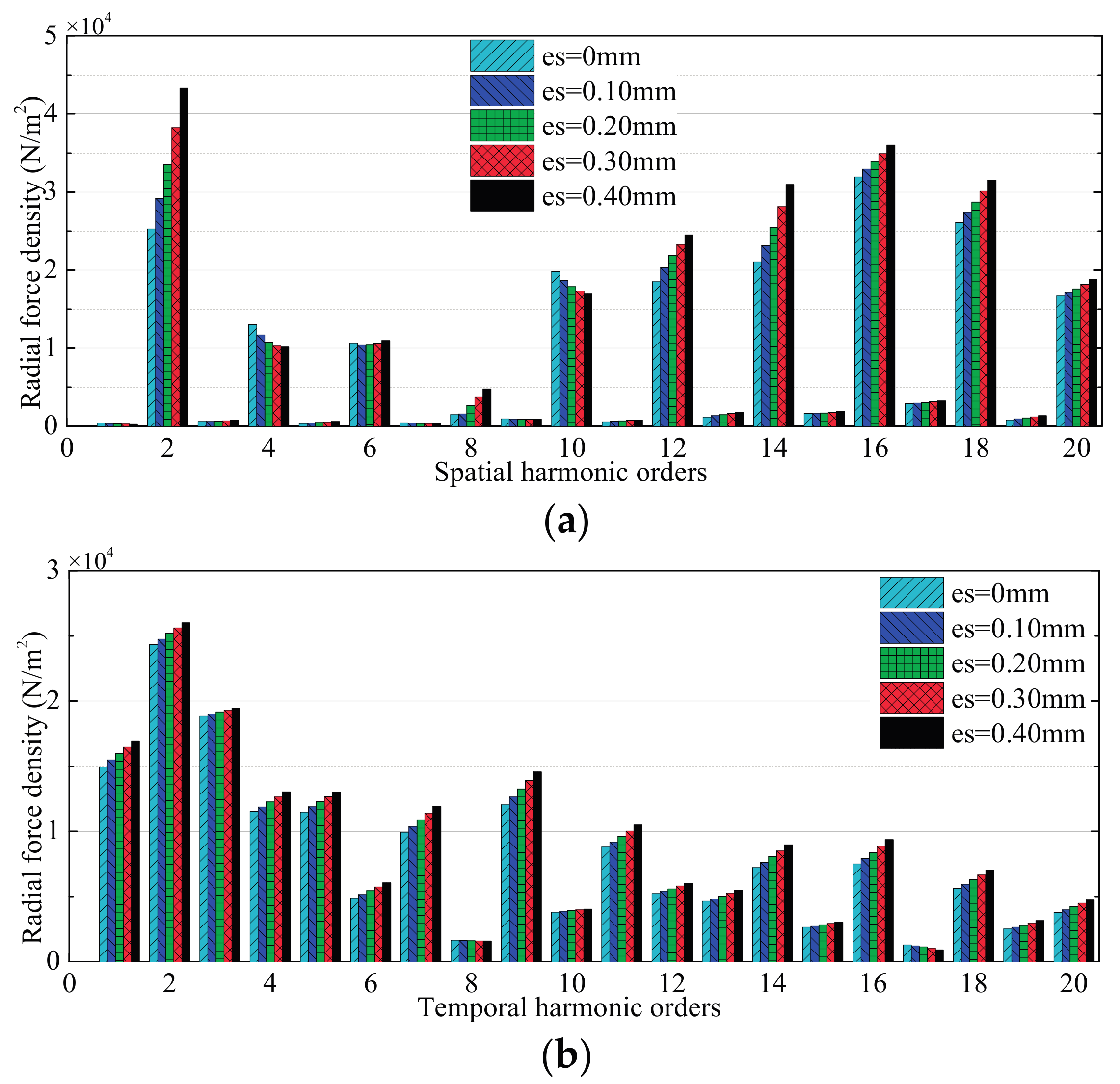
Harmonic contents of radial force density in the IPMSM with stator deformation at no-load condition. (a) Spatial harmonics; (b) Temporal harmonics.
The electromagnetic FEM of the IPMSM considering air-gap deformation in this paper has taken into account rotor saliency, stator slots, and magnetic saturation. Thus, the 10th harmonic of magnetic flux density, which appears in the FEA results, mainly comes from the effect of the slotted stator when the air-gap deformation is equal to 0. With the ovality of the stator increasing from 0 to 40%, the 10th harmonic content of radial magnetic flux density increases to a much greater extent than others. The result is consistent with the theoretical analysis in Equation (13), which indicates that the (p ± 2)th harmonic is the main additional content of radial flux density due to the stator deformation at no-load condition. In this case, (14, 2f) and (18, 2f) are the main additional contents of radial force density according to the theoretical results in Equation (18) and Table 3. The FEA results show that (2, 2f), (14, 2f) and (18, 2f) increase greatly with the stator deformation increasing, which is consistent with the theoretical results. However, among all these additional contents, (2, 2f) is mainly caused by the slotted stator, which is not considered in the theoretical analysis.
3.1.2. High-Speed Load Condition
As is well known, both the amplitude and the frequency of radial force density are important in relation to vibration behavior of the machine and they vary significantly from no-load to on-load conditions. In the high-speed load operation, the IPMSM is operating at the flux-weakening area so that a larger d-axis demagnetizing current is required. This makes the harmonic contents of magnetic flux density change a great deal.
Figure 7 illustrates the analysis of the radial component of air-gap flux density in the IPMSM with stator deformation at high-speed load condition. In this case, the radial force density comes from the interaction of the permanent magnet field and the armature reaction field. Combined with Equations (14) and (15), the main additional harmonics of radial flux density due to the stator deformation at a high-speed load condition is similar to those at no-load condition. The only difference is the increasing rate of the (p ± 2)th harmonic, which is also verified by the FEA.
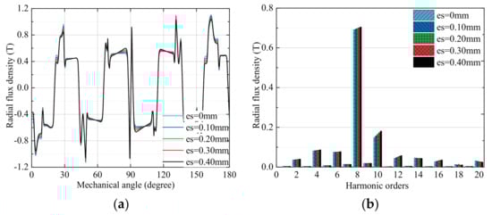
Figure 7.
Analysis of the radial component of magnetic flux density in the IPMSM with stator deformation at high-speed load condition. (a) Distribution curves; (b) Harmonic contents.
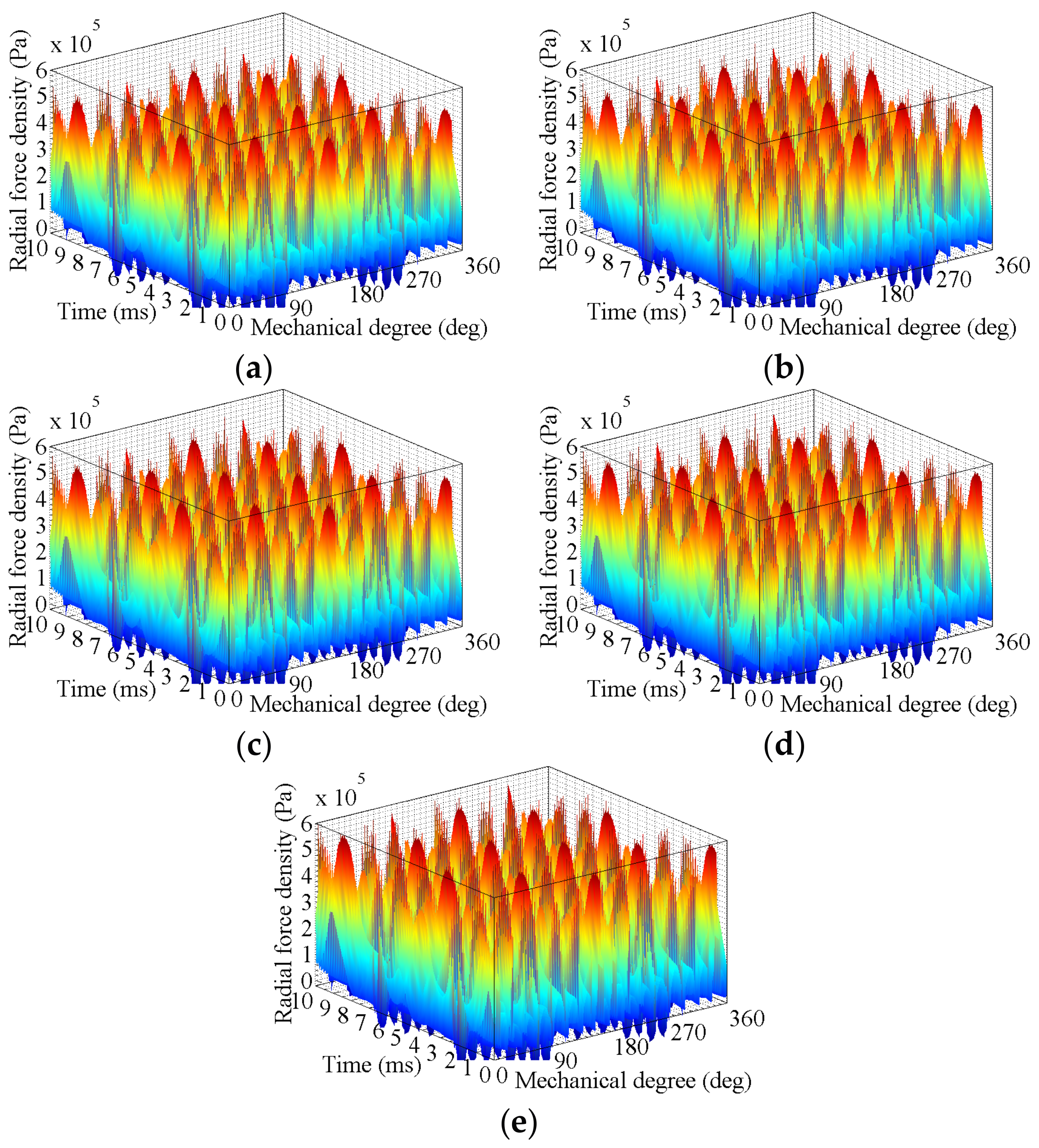
Figure 8 and Figure 9 show the three-dimensional waveform and the harmonic analysis of radial force density in this case, respectively. Similarly, (14, 2f) and (18, 2f) are also the main additional contents at high-speed load condition. In addition, due to the involvement of the armature reaction field, the increasing rate of the (2p ± 4, 2f) becomes much greater. As is shown in Table 3, good agreements between theoretical analysis results and FEA results have been achieved in the two mentioned cases.

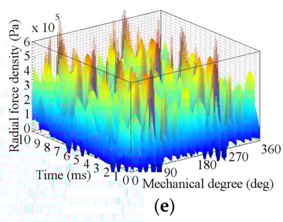
Figure 8.
Radial force density in the IPMSM with stator deformation at high-speed load condition. (a) es = 0 mm; (b) es = 0.1 mm; (c) es = 0.2 mm; (d) es = 0.3 mm; (e) es = 0.4 mm.

Figure 9.
Harmonic contents of radial force density in the IPMSM with stator deformation at high-speed load condition. (a) Spatial harmonics; (b) Temporal harmonics.
In fact, except the zero order, the lowest value of the radial force density is equal to the greatest common divisor of the pole and slot number. It should be noted that the lowest order of the radial force density is very important for the vibration behavior of the motor at different loading conditions. Since the lowest order of this 16p18s IPMSM with fractional-slot concentrated windings is second order, the (2, 2f) among all additional contents has the most important influence on the electromagnetic vibration. Therefore, the radial magnetic force density of the investigated IPMSM with deformed stator increases the vibration level greatly, and the vibration at high-speed load condition is greater than that at the no-load condition.
3.2. Effects of Rotor Deformation
3.2.1. No-Load Condition
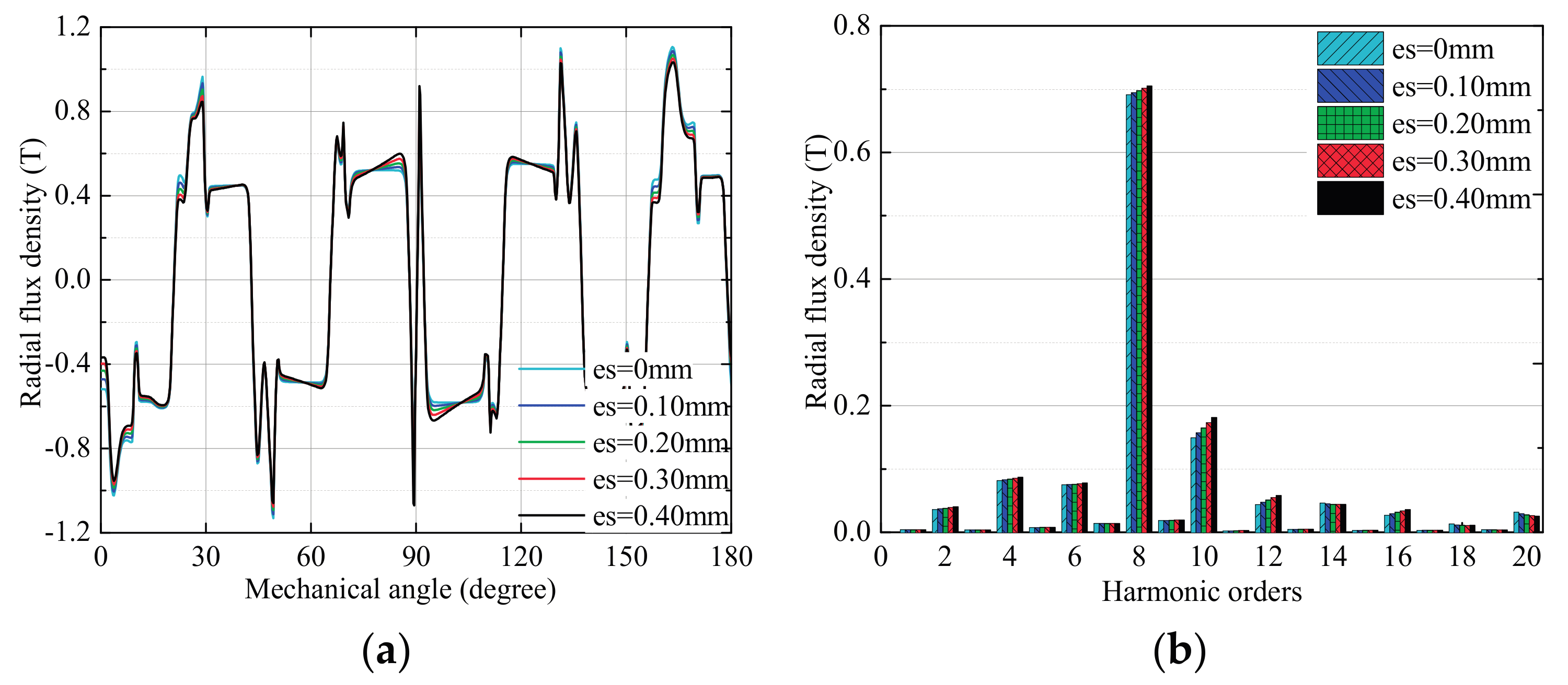
Similar to the analysis of the stator oval deformation, with the relative deformation of the rotor pole shoe increasing from 0 to 40%, the analysis of the radial component of air-gap flux density in the IPMSM at no-load condition is given in Figure 10. The three-dimensional waveform and the harmonic contents analysis of corresponding radial force density are shown in Figure 11 and Figure 12, respectively.
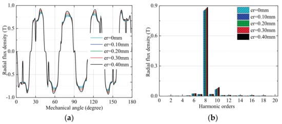
Figure 10.
Analysis of the radial component of magnetic flux density in the IPMSM with rotor deformation at no-load condition. (a) Distribution curves; (b) Harmonic contents.

Figure 11.
Radial force density in the IPMSM with rotor deformation at no-load condition. (a) es = 0 mm; (b) er = 0.1 mm; (c) er = 0.2 mm; (d) er = 0.3 mm; (e) er = 0.4 mm.
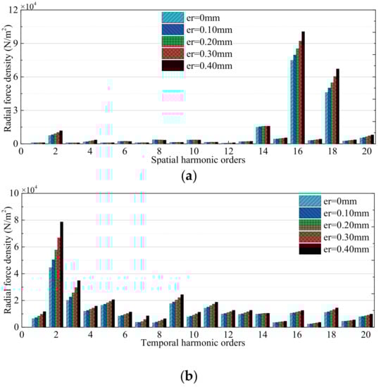
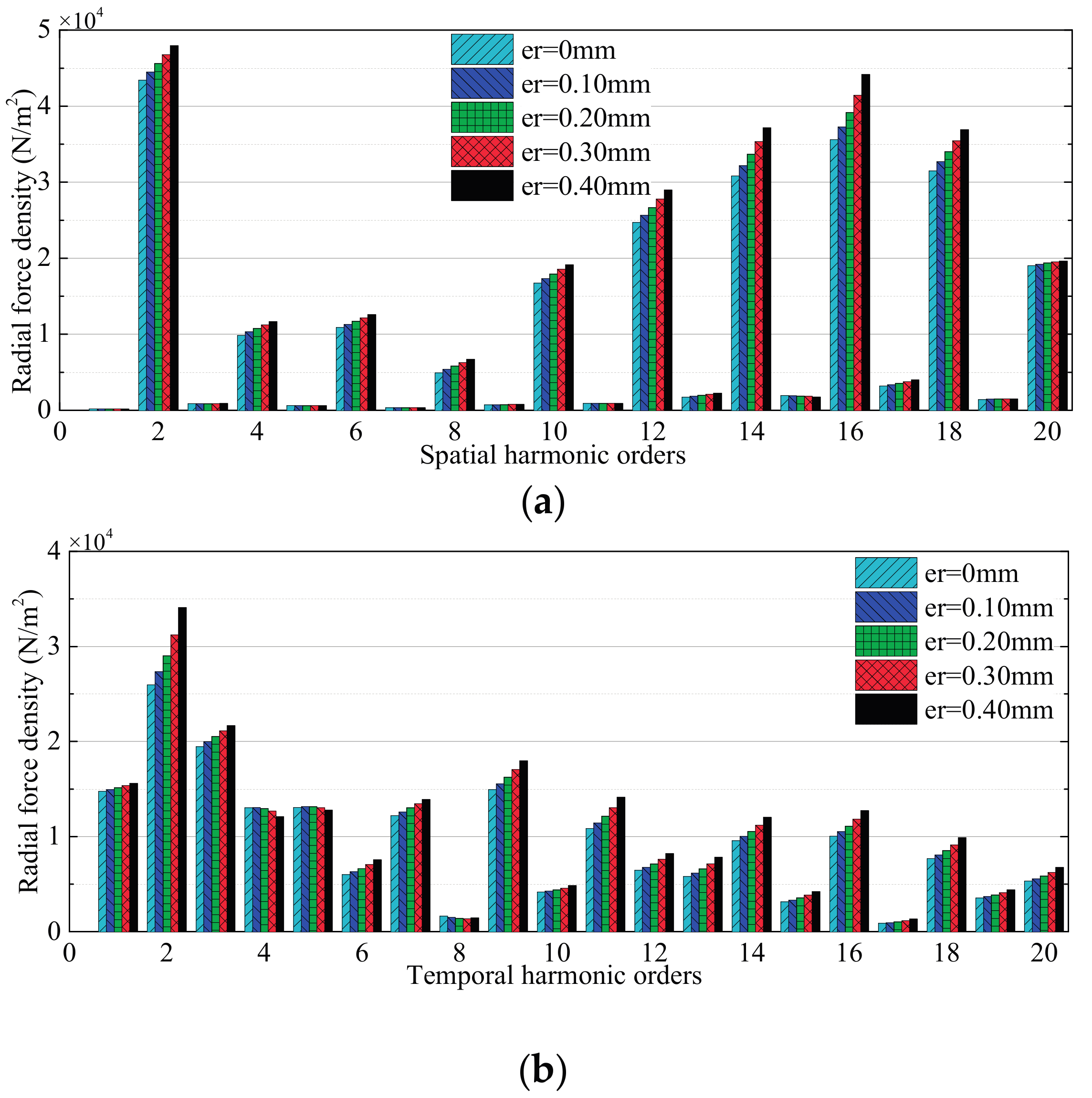
Figure 12.
Harmonic contents of radial force density in the IPMSM with rotor deformation at no-load condition. (a) Spatial harmonics; (b) Temporal harmonics.
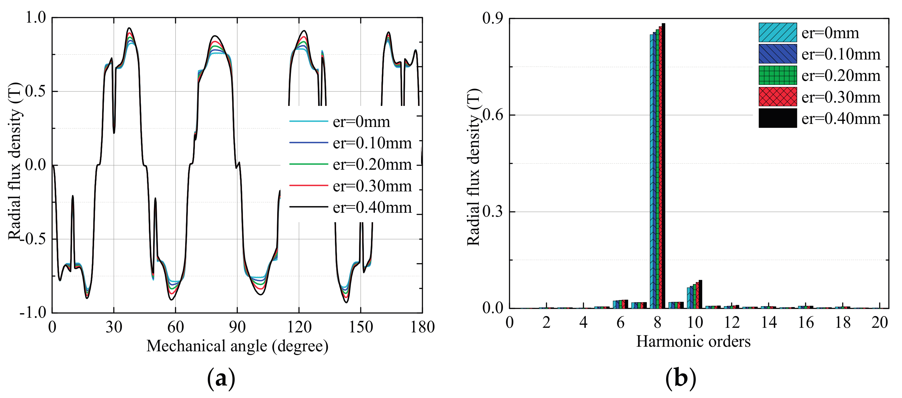
Unlike the stator oval deformation, the effect of rotor deformation is related to the number of poles, 2p. The average air-gap length reduces due to the rotor core deformation, which could lead to an increase in the average permeance. According to Equation (15), the 8th harmonic, which is the main wave content of the investigated IPMSM, has a significant increase due to rotor deformation. However, the 10th harmonic content also increases to a greater extent than others because of the effect of the slotted stator core on the air-gap permeance. As a consequence, the (2p, 2f) of radial magnetic force density is the main additional content due to rotor deformation, which is shown in Table 3. In addition, the interaction of the rotor magnetic field and the slotted structure of the stator at no-load condition mainly produces the (2, 2f) and (2p ± 2, 2f) contents. With the rotor deformation becoming large, the magnitude of these contents would have a corresponding increase in Figure 12.
3.2.2. High-Speed Load Condition
Figure 13 illustrates the analysis of the radial air-gap flux density in the IPMSM with rotor deformation at high-speed load condition. Figure 14 and Figure 15 show the three-dimensional waveform and the harmonic analysis of radial force density in this case, respectively. The FEA results shown in Figure 13 indicate that the variation trend of the 8th harmonic of flux density at loading condition is the same as that at no-load condition, which has been presented in Table 3. The 10th harmonic is weakly influenced by rotor deformation at this case and this may be caused by the larger d-axis demagnetizing current. In addition, due to the increasing of fundamental flux field, the additional content of radial force density concentrates in the (16, 2f). As mentioned before, the (2, 2f) and (2p ± 2, 2f) contents result from the slotted stator.
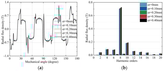
Figure 13.
Analysis of the radial component of magnetic flux density in the IPMSM with rotor deformation at high-speed load condition. (a) Distribution curves; (b) Harmonic contents.
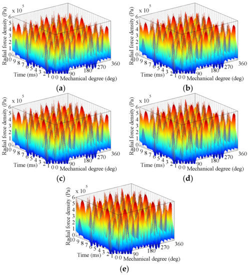
Figure 14.
Radial force density in the IPMSM with rotor deformation at high-speed load condition. (a) er = 0 mm; (b) er = 0.1 mm; (c) er = 0.2 mm; (d) er = 0.3 mm; (e) er = 0.4 mm.
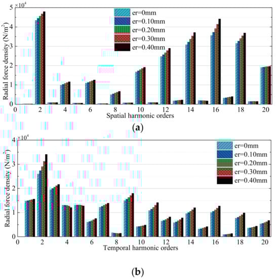
Figure 15.
Harmonic contents of radial force density in the IPMSM with rotor deformation at high-speed load condition. (a) Spatial harmonics; (b) Temporal harmonics.
It should be noted that the increase of the lowest order (2, 2f) will lead to a corresponding increase in the vibration level of the investigated 16p18s IPMSM at high-speed load condition. In fact, the lowest order of the radial force density in the IPMSM with integer-slot windings, for example, 8p48s, is equal to the number of poles. Thus, the pole shoe deformation can lead to a higher lowest-order spatial harmonic, which has a significant effect on the vibration.
Since the stator slots and magnetic saturation have not been taken into account, there are some differences between the results of theoretical analysis and the FEA. In order to analyze the harmonics clearly, all factors including current harmonics, stator slots and magnetic saturation combined with stator and rotor deformations will be considered in the following research.
4. Vibration Experiments
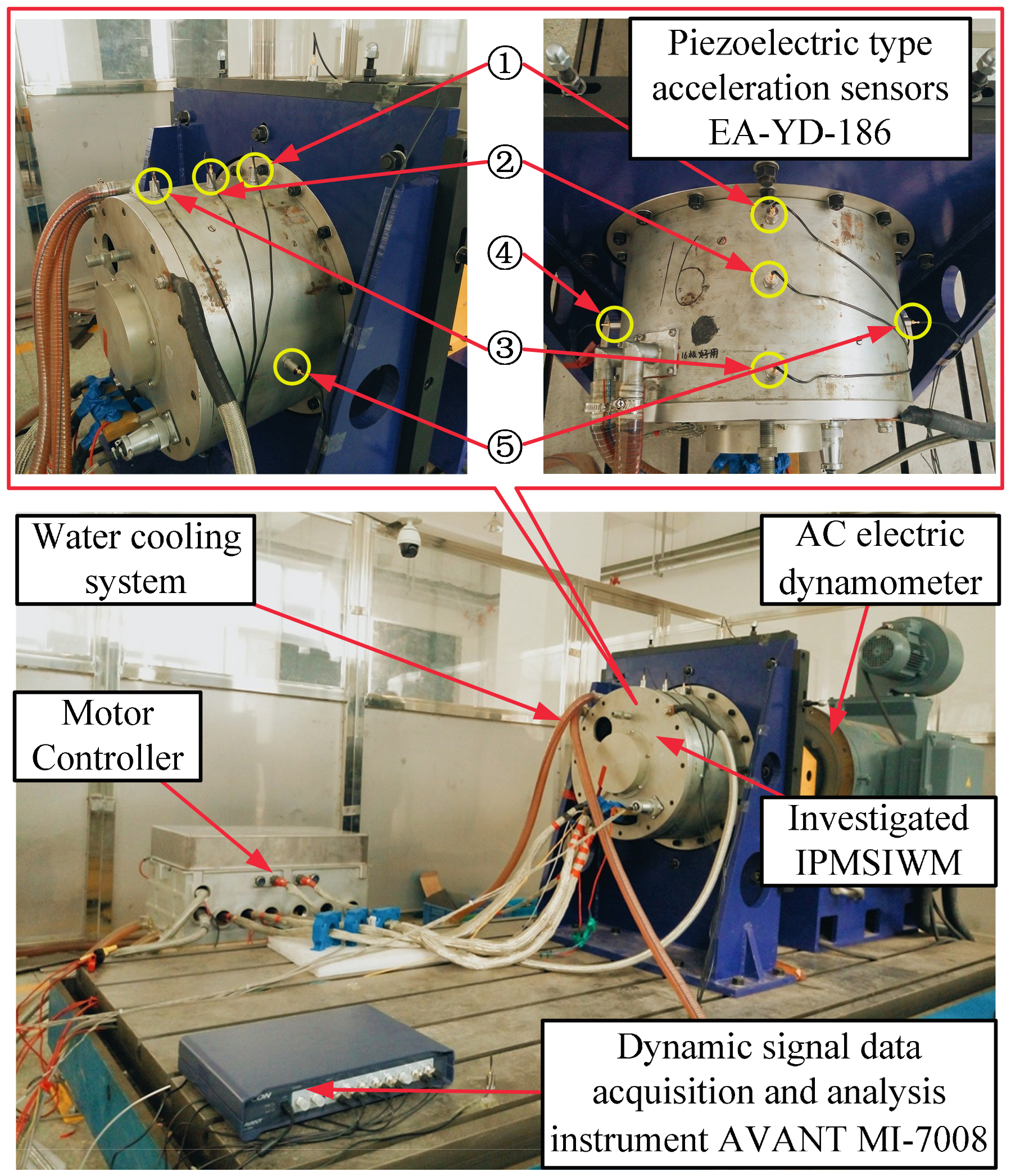
With the prototype of the investigated IPMSM fabricated, the motor vibration experiments at different operations have been carried out. Figure 16 shows the experimental platform for the IPMSM prototype. The instruments applied in the experiments are illustrated in the figure. When the prototype has run for a long time at different operations, the corresponding vibrating spectral analysis in these cases is recorded in Figure 17.
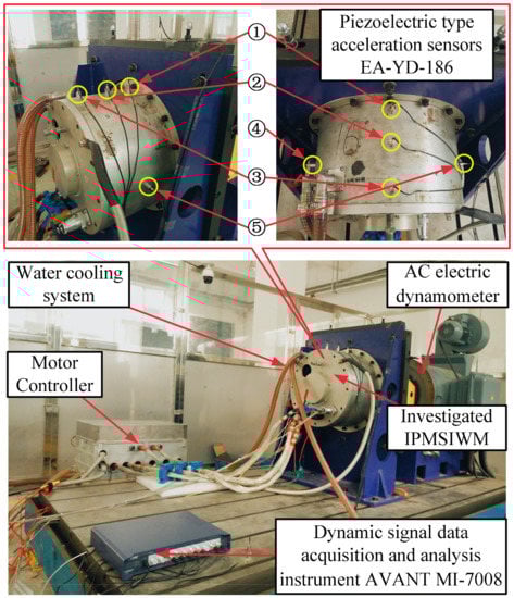
Figure 16.
Experimental platform for the investigated IPMSM prototype.
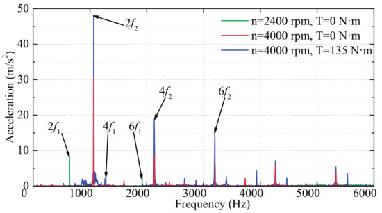
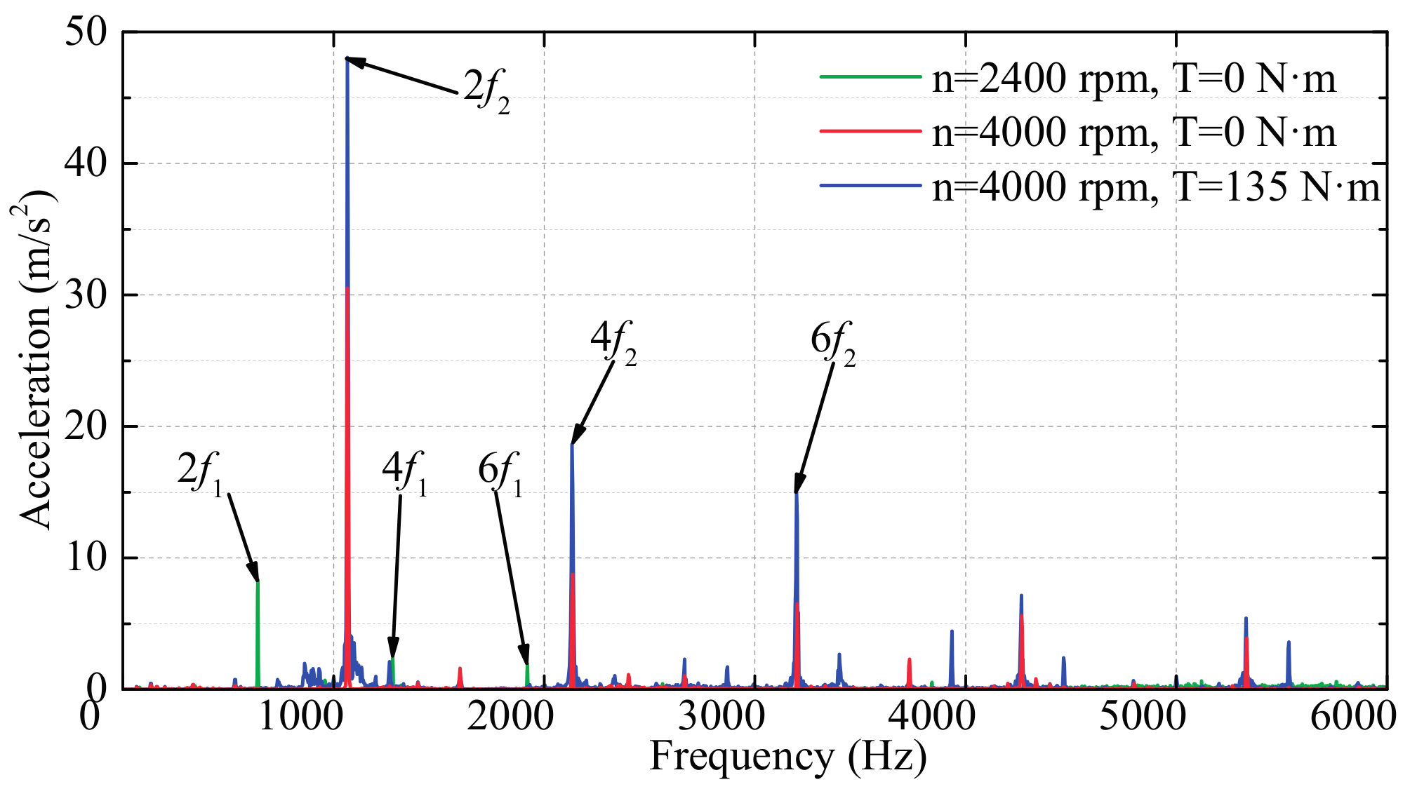
Figure 17.
The vibrating spectral analysis of the investigated IPMSM prototype at different operations. (f1 and f2 are the fundamental frequencies of the rotating magnetic field at rated speed and peak speed, respectively.)
In fact, the deformation of the inner surface of the stator core have been measured before the IPMSM prototype assembly. The maximum deformation is approximately equal to 0.01 mm, which is much smaller than the air-gap length. Moreover, the radial impacting loads from the excitations of different road surfaces cannot be simulated on this platform. Thus, the effect of the stator deformation on the vibration is small and difficult to observe in this prototype.
Meanwhile, in the whole process of the vibration experiments, the prototype has a mechanical resonance when the rotating speed is at about 3300 rpm. The peak-speed operating point is far from the resonance area. Thus, it is possible to determine that the mechanical resonance of the stator system is not the cause of the increase of surface vibration acceleration at no-load condition.
In addition, through the thermal analysis of the IPMSM prototype, the steady-state temperature rise at high-speed condition is about 100 °C. Therefore, the maximum thermal deformation of the pole shoe is calculated to be about 0.2 mm by software ABAQUS 6.12 (SIMULIA, Velizy Villacoublay, France), where the thermal expansion coefficient of the rotor core is equal to 13.5 × 10⁻⁶ 1/°C. Compared with the air-gap length, the thermal deformation of the pole shoe is relatively large, which indicates that its effect is really significant. Meanwhile, rotor centrifugal distortion of the IPMSM prototype at peak speed is also obtained by ABAQUS, and the maximum value is about 0.12 mm. Through the superposition of thermal deformation and centrifugal distortion, the rotor deformation of the IPMSM prototype would increase significantly for a long time operation at peak speed.
The results in Figure 17 indicate that the vibration acceleration of the prototype increases greatly when the rotating speed rises from the rated value to maximum value at no-load condition. In addition, the vibration level at the high-speed load condition also has a certain increase compared with that at no-load condition, which is mainly caused by the non-sinusodial stator current fed from the pulse width modulation inverter in the experiments. Therefore, according to the results of the theoretical analysis and FEA, the rotor pole shoe deformation should be one of the main causes that lead to an increase in the vibration level.
5. Conclusions
The work presented in this paper deals with a detailed analysis of the air-gap deformation, together with its effects on the radial magnetic force density in an IPMSM.
According to the formulations of flux field and radial force density derived in the theoretical analysis, it is concluded that the additional harmonic contents of radial force density caused by the stator oval deformation are (2p ± 2, 2f) and (2p ± 4, 2f), and the additional content caused by the rotor deformation is (2p, 2f). With the stator oval deformation and the rotor centrifugal distortion considering in the electromagnetic FEMs, all these results have been verified by the FEA; the (2, 2f) has also increased because of the slotted stator, which is not taken into account in the theoretical analysis. Combined with the results of the theoretical analysis and FEA, the experiments of the IPMSM prototype at different operations can verify that the rotor deformation is an important factor which affects the vibration level when the rotating speed rises up to a certain value.
All of the results indicate that considering the air-gap deformation helps to accurately predict and evaluate the vibration level and easily solve problems of mutual influence between electromagnetic and mechanical characteristics during the optimization design of IPMSM, which would be investigated in the further study.
Acknowledgments
This study was carried out as a part of the industrial application technology in electric vehicles and supported by the National Natural Science Foundation of China (51677039) and Self-Planned Task (NO. SKLRS201608B) of the State Key Laboratory of Robotics and System (HIT).
Author Contributions
This paper is the results of the hard work of all authors. Yi Li and Feng Chai conceived and designed the idea. Zongyang Li and Zaixin Song built the FEM models and analyze the data. Yi Li wrote the paper. All authors gave advices for the manuscripts.
Conflicts of Interest
The authors declare no conflict of interest.
Nomenclature
| Rso, Rsi | Outer and inner radii of the stator core |
| Rro, Rri | Outer and inner radii of the rotor core |
| lm, hm | Length and height of the PM |
| hmb | Thickness of magnetic bridge |
| hmr | Thickness of magnetic rib |
| μ0 | Magnetic permeability of free space |
| g0 | Average air-gap length in a healthy IPMSM |
| Λ0 | Relative permeance of the smooth air-gap |
| α | Mechanical angle of the rotor position |
| p | Number of pole-pairs |
| es1, es2 | Values of maximum and minimum stator deformations |
| er1, er2 | Values of maximum and minimum rotor deformations |
| δs1, δs2 | Values of maximum and minimum relative stator deformations |
| δr1, δr2 | Values of maximum and minimum relative rotor deformations |
| Λg(α, t) | Relative permeance of the deformed air-gap |
| λg(α, t) | Relative specific permeance of the deformed air-gap |
| gs(α) | Radial air-gap length of the stator oval deformation |
| gr(α, t) | Radial air-gap length of the rotor centrifugal distortion |
| λgs(α) | Relative specific permeance of the air-gap with stator deformation (dimensionless) |
| λgr(α, t) | Relative specific permeance of the air-gap with rotor deformation (dimensionless) |
| αs1 | Cofficient, which is defined as αs1 = (δs1 + δs2)/2 |
| αr0 | Cofficient, which is defined as αr0 = (δr1 + δr2)/2 |
| αr1 | Cofficient, which is defined as αr1 = (δr1 − δr2)/2 |
| v | Number of stator MMF harmonics |
| μ | Number of rotor MMF harmonics |
| ωr | Rotor mechanical angular frequency |
| ω | Current angular frequency |
| Fmv | Magnitude of the v-th harmonic of stator MMF |
| Fmμ | Magnitude of the μ-th harmonic of rotor MMF |
| ωμ | Electrical angular frequency of rotor harmonics |
| ϕμ | Angle between vectors of the stator and rotor harmonics of equal order |
References
- Liu, X.; Chen, H.; Zhao, J.; Belahcen, A. Research on the performances and parameters of interior PMSM used for electric vehicles. IEEE Trans. Ind. Electron. 2016, 63, 3533–3545. [Google Scholar] [CrossRef]
- Liang, P.; Pei, Y.; Chai, F.; Zhao, K. Analytical calculation of d-and q-axis inductance for interior permanent magnet motors based on winding function theory. Energies 2016, 9, 580. [Google Scholar] [CrossRef]
- Zheng, P.; Wu, F.; Lei, Y.; Sui, Y.; Yu, B. Investigation of a Novel 24-Slot/14-Pole Six-Phase Fault-Tolerant Modular Permanent-Magnet In-Wheel Motor for Electric Vehicles. Energies 2013, 6, 4980–5002. [Google Scholar] [CrossRef]
- Chai, F.; Liang, P.; Pei, Y.; Cheng, S. Analytical Method for Iron Losses Reduction in Interior Permanent Magnet Synchronous Motor. IEEE Trans. Magn. 2015, 51, 1–4. [Google Scholar] [CrossRef]
- Gu, W.; Zhu, X.; Quan, L.; Du, Y. Design and Optimization of Permanent Magnet Brushless Machines for Electric Vehicle Applications. Energies 2015, 8, 13996–14008. [Google Scholar] [CrossRef]
- Zhao, J.; Liu, W.; Li, B.; Liu, X.; Gao, C.; Gu, Z. Investigation of Electromagnetic, Thermal and Mechanical Characteristics of a Five-Phase Dual-Rotor Permanent-Magnet Synchronous Motor. Energies 2015, 8, 9688–9718. [Google Scholar] [CrossRef]
- Lin, F.; Zuo, S.; Deng, W.; Wu, S. Modeling and analysis of electromagnetic force, vibration, and noise in permanent-magnet synchronous motor considering current harmonics. IEEE Trans. Ind. Electron. 2016, 63, 7455–7466. [Google Scholar] [CrossRef]
- Gieras, J.F.; Wang, C.; Lai, J.C. Noise of Polyphase Electric Motors, 1st ed.; CRC Press: Boca Raton, FL, USA, 2006. [Google Scholar]
- Chai, F.; Li, Y.; Liang, P.; Pei, Y. Calculation of the maximum mechanical stress on the rotor of interior permanent-magnet synchronous motors. IEEE Trans. Ind. Electron. 2016, 63, 3420–3432. [Google Scholar] [CrossRef]
- Zuo, S.; Lin, F.; Wu, X. Noise analysis, calculation, and reduction of external rotor permanent-magnet synchronous motor. IEEE Trans. Ind. Electron. 2015, 62, 6204–6212. [Google Scholar] [CrossRef]
- Urresty, J.C.; Atashkhooei, R.; Riba, J.R.; Romeral, L.; Royo, S. Shaft trajectory analysis in a partially demagnetized permanent-magnet synchronous motor. IEEE Trans. Ind. Electron. 2013, 60, 3454–3461. [Google Scholar] [CrossRef]
- Di, C.; Bao, X.; Wang, H.; Lv, Q.; He, Y. Modeling and analysis of unbalanced magnetic pull in cage induction motors with curved dynamic eccentricity. IEEE Trans. Magn. 2015, 51, 8106507. [Google Scholar]
- Ebrahimi, B.M.; Faiz, J.; Roshtkhari, M.J. Static-, dynamic-, and mixed-eccentricity fault diagnoses in permanent-magnet synchronous motors. IEEE Trans. Ind. Electron. 2009, 56, 4727–4739. [Google Scholar] [CrossRef]
- Park, J.K.; Hur, J. Detection of inter-turn and dynamic eccentricity faults using stator current frequency pattern in IPM-type BLDC motors. IEEE Trans. Ind. Electron. 2016, 63, 1771–1780. [Google Scholar] [CrossRef]
- Ebrahimi, B.M.; Roshtkhari, M.J.; Faiz, J.; Khatami, S.V. Advanced eccentricity fault recognition in permanent magnet synchronous motors using stator current signature analysis. IEEE Trans. Ind. Electron. 2014, 61, 2041–2052. [Google Scholar] [CrossRef]
- López-Torres, C.; Riba, J.R.; Garcia, A.; Romeral, L. Detection of Eccentricity Faults in Five-Phase Ferrite-PM Assisted Synchronous Reluctance Machines. Appl. Sci. 2017, 7, 565. [Google Scholar] [CrossRef]
- Li, Y.; Lu, Q.; Zhu, Z.Q.; Wu, L.J.; Li, G.J.; Wu, D. Analytical synthesis of air-gap field distribution in permanent magnet machines with rotor eccentricity by superposition method. IEEE Trans. Magn. 2015, 51, 8110404. [Google Scholar] [CrossRef]
- Babaei, M.; Faiz, J.; Ebrahimi, B.M.; Amini, S.; Nazarzadeh, J. A detailed analytical model of a salient-pole synchronous generator under dynamic eccentricity fault. IEEE Trans. Magn. 2011, 47, 764–771. [Google Scholar] [CrossRef]
- Zhang, G.; Wu, J.; Hao, L. Fast Calculation Model and Theoretical Analysis of Rotor Unbalanced Magnetic Pull for Inter-Turn Short Circuit of Field Windings of Non-Salient Pole Generators. Energies 2017, 10, 732. [Google Scholar] [CrossRef]
- Jiang, J.W.; Bilgin, B.; Sathyan, A.; Dadkhah, H.; Emadi, A. Analysis of unbalanced magnetic pull in eccentric interior permanent magnet machines with series and parallel windings. IET Electr. Power Appl. 2016, 10, 526–538. [Google Scholar] [CrossRef]
- Cappelli, L.; Coia, Y.; Marignetti, F.; Zhu, Z.Q. Analysis of eccentricity in permanent-magnet tubular machines. IEEE Trans. Ind. Electron. 2014, 61, 2208–2216. [Google Scholar] [CrossRef]
- Ebrahimi, B.M.; Faiz, J. Magnetic field and vibration monitoring in permanent magnet synchronous motors under eccentricity fault. IET Electr. Power Appl. 2012, 6, 35–45. [Google Scholar] [CrossRef]
- Biček, M.; Gotovac, G.; Miljavec, D.; Zupan, S. Mechanical Failure Mode Causes of In-Wheel Motors. J. Mech. Eng. 2015, 61, 74–85. [Google Scholar] [CrossRef]
- Heuler, P.; Klätschke, H. Generation and use of standardised load spectra and load–time histories. Int. J. Fatigue 2005, 27, 974–990. [Google Scholar] [CrossRef]
- Heuler, P.; Bruder, T.; Klätschke, H. Standardised load-time histories—A contribution to durability issues under spectrum loading. Materwiss Werksttech 2005, 36, 669–677. [Google Scholar] [CrossRef]
- Valavi, M.; Nysveen, A.; Nilssen, R.; Rølvåg, T. Slot harmonic effect on magnetic forces and vibration in low-speed permanent-magnet machine with concentrated windings. IEEE Trans. Ind. Appl. 2014, 50, 3304–3313. [Google Scholar] [CrossRef]
- Tan-Kim, A.; Hagen, N.; Lanfranchi, V.; Clénet, S.; Coorevits, T.; Mipo, J.C.; Palleschi, F. Influence of the manufacturing process of a claw-pole alternator on its stator shape and acoustic noise. In Proceedings of the 2016 XXII International Conference on Electrical Machines (ICEM), Lausanne, Switzerland, 4–7 September 2016; pp. 2273–2279. [Google Scholar]
- Lv, Q.; Fang, Y.; Cheng, Z.; Bao, X. Finite element analysis of a squirrel cage induction motor with an oval stator under eccentricity conditions. In Proceedings of the 2013 5th International Conference on Power Electronics Systems and Applications (PESA), Hong Kong, China, 11–13 December 2013; pp. 1–5. [Google Scholar]
- Putri, A.K.; Rick, S.; Franck, D.; Hameyer, K. Application of Sinusoidal Field Pole in a Permanent-Magnet Synchronous Machine to Improve the NVH Behavior Considering the MTPA and MTPV Operation Area. IEEE Trans. Ind. Appl. 2016, 52, 2280–2288. [Google Scholar] [CrossRef]


© 2017 by the authors. Licensee MDPI, Basel, Switzerland. This article is an open access article distributed under the terms and conditions of the Creative Commons Attribution (CC BY) license (http://creativecommons.org/licenses/by/4.0/).