Analysis of the Input Current Distortion and Guidelines for Designing High Power Factor Quasi-Resonant Flyback LED Drivers


 and
and
Abstract
:1. Introduction
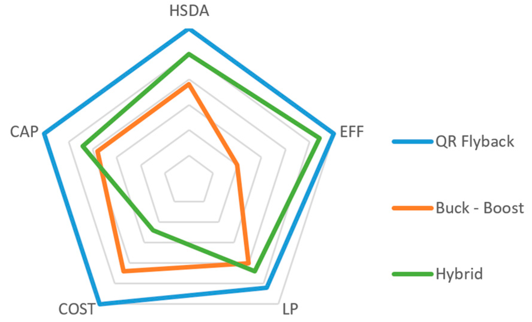
2. Brief Overview of LED Driver Topologies
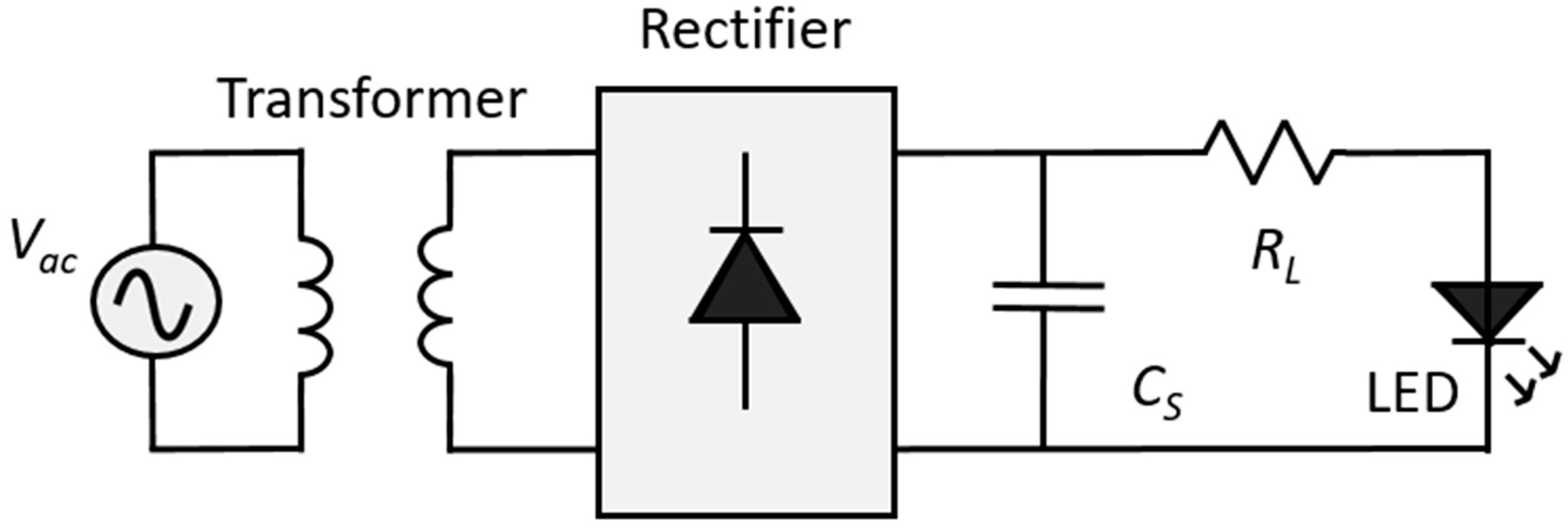
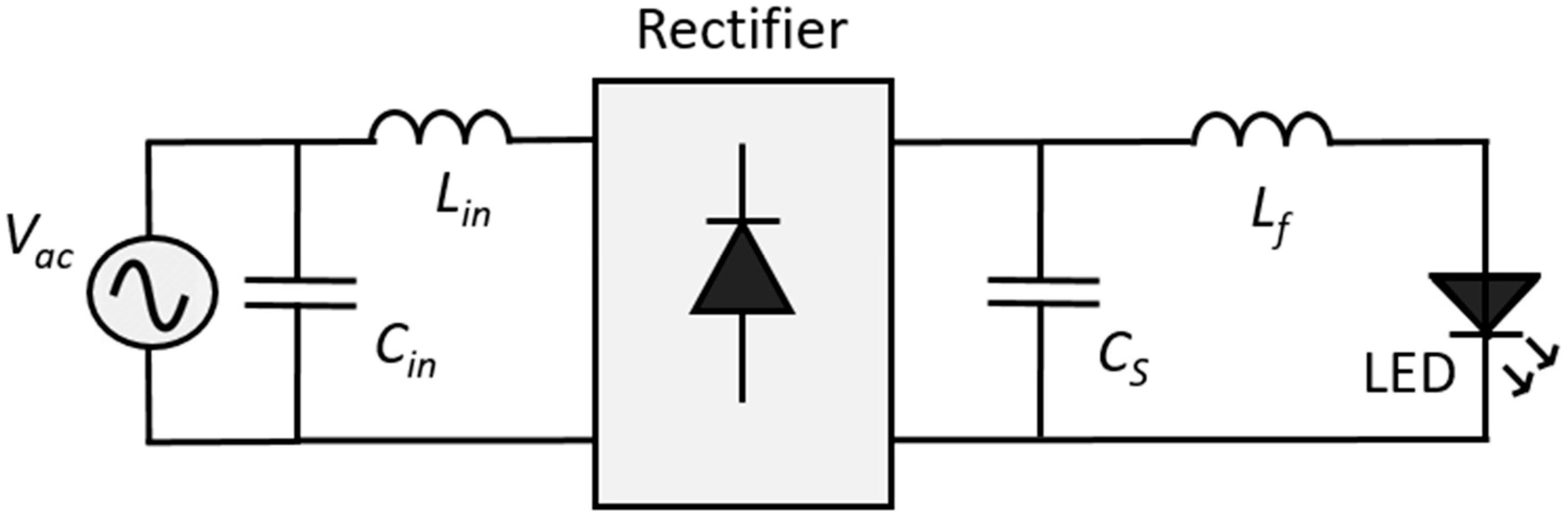
2.1. Passive LED Drivers
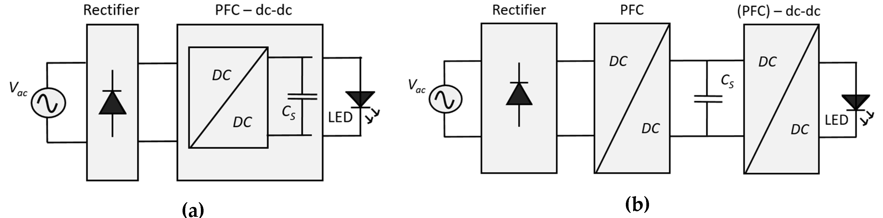
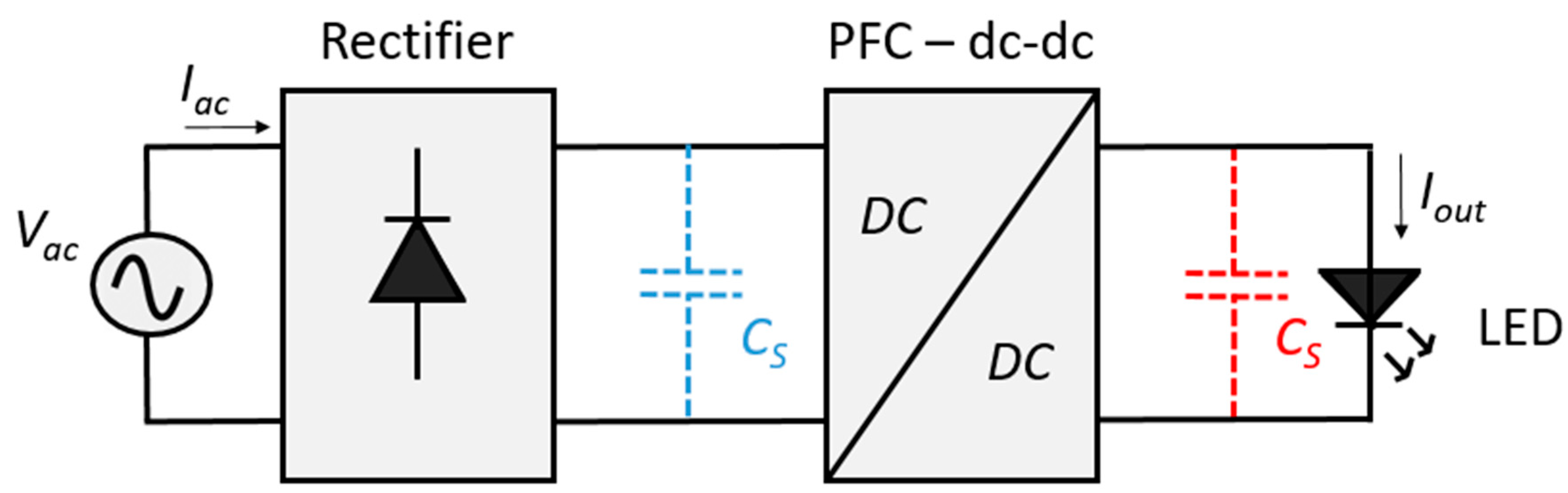
2.2. Switching LED Driver
3. Analysis of Input Current Distortion due to Power Processing and Power Circuit
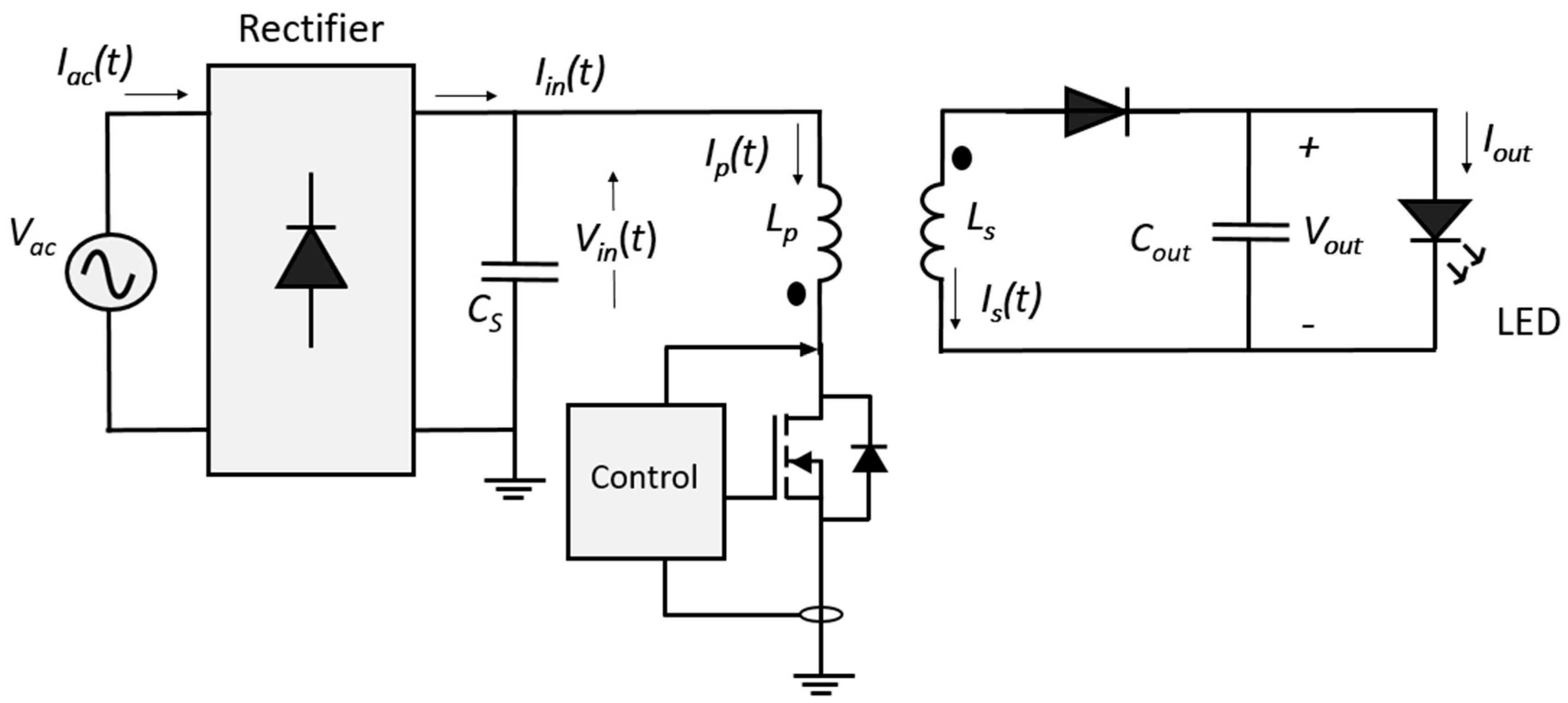
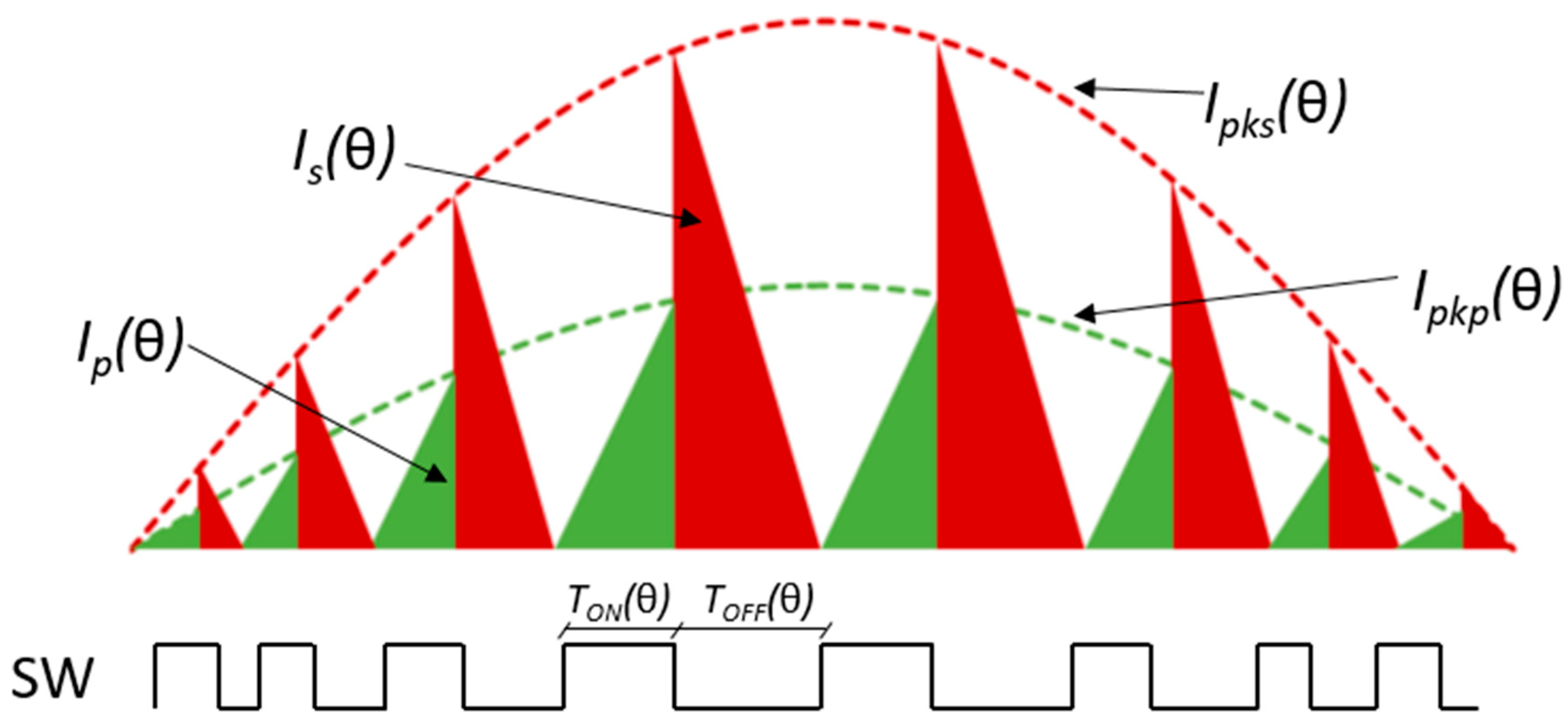
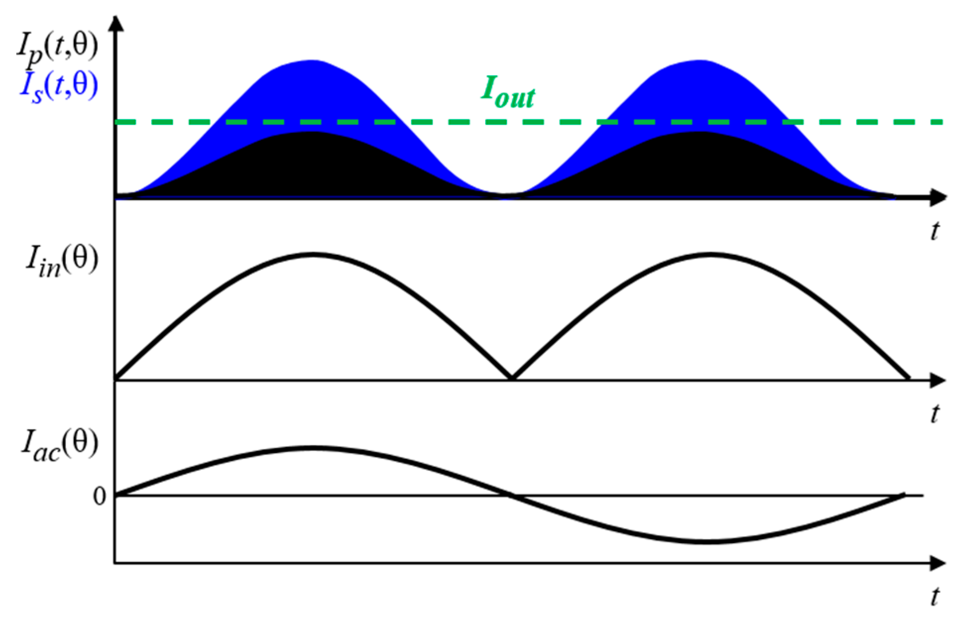
3.1. Generic Control Method Obtaining High Power Factor
- The line voltage is sinusoidal, and the input bridge rectifier is ideal, thus the voltage at the bridge output terminal is a rectified sinusoid.
- The voltage drop across the power switch in the on-state is negligible and there is negligible energy accumulation on the dc side of the bridge.
- The transformer windings are perfectly coupled (i.e., no leakage inductance).
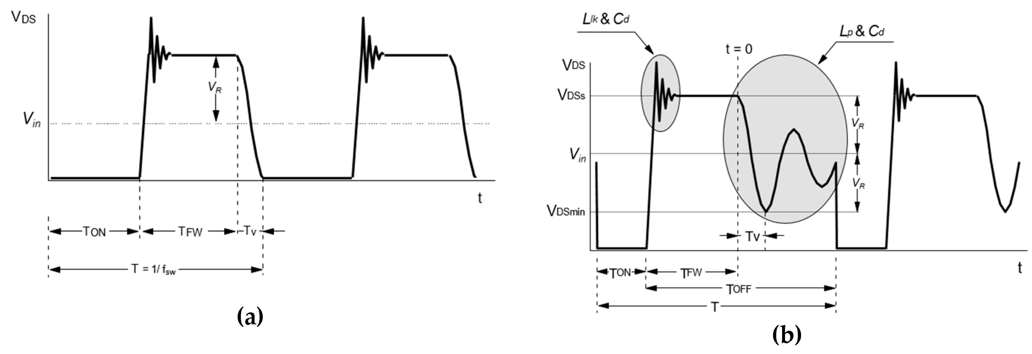
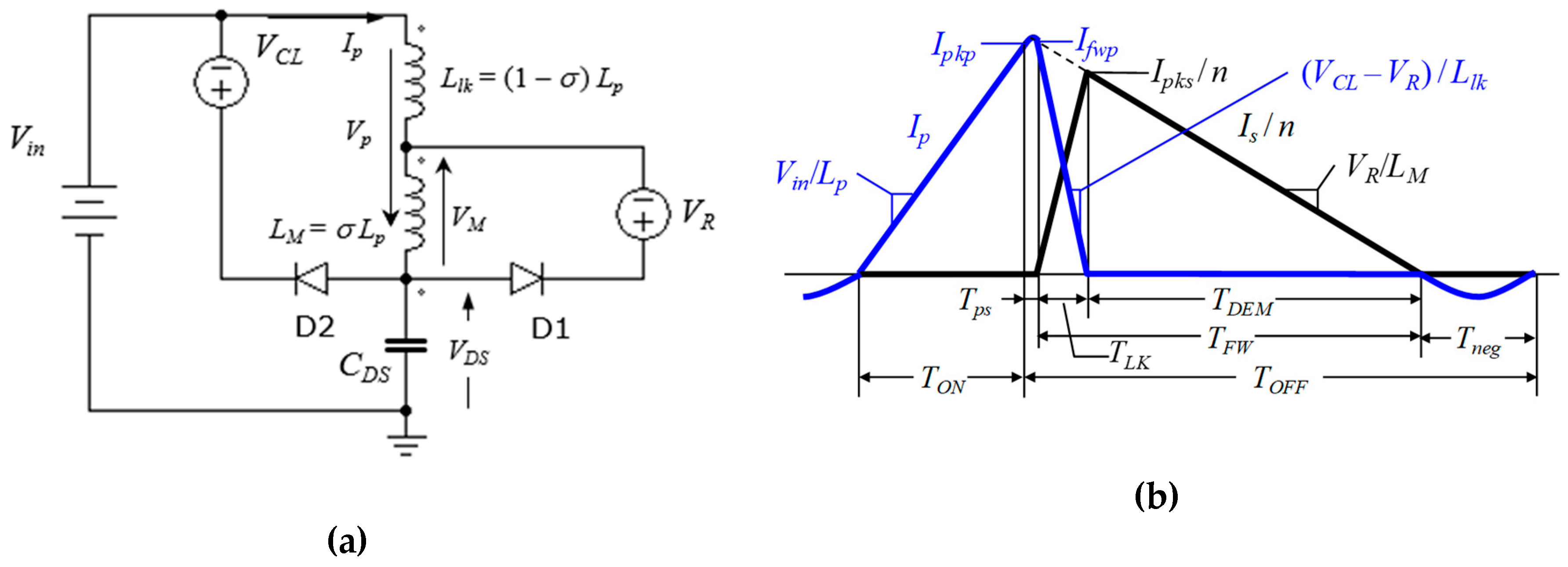
- The turn-off transient of the power switch has negligible duration so that TFW immediately follows TON.
- The converter is operated so the power switch is turned on in each cycle after the secondary current becomes zero, therefore in either QR-mode (i.e., on the first valley of the ringing in the drain–source voltage) or DCM.
- The output voltage is constant along a line half-cycle.
- During the time interval elapsing from the instant when the transformer demagnetizes to the instant when the power switch is turned on, the transformer current is zero; consequently, the initial current during the on-time is zero too. This time interval is equal to Tr/2 in the case of the converter being used in QR mode.
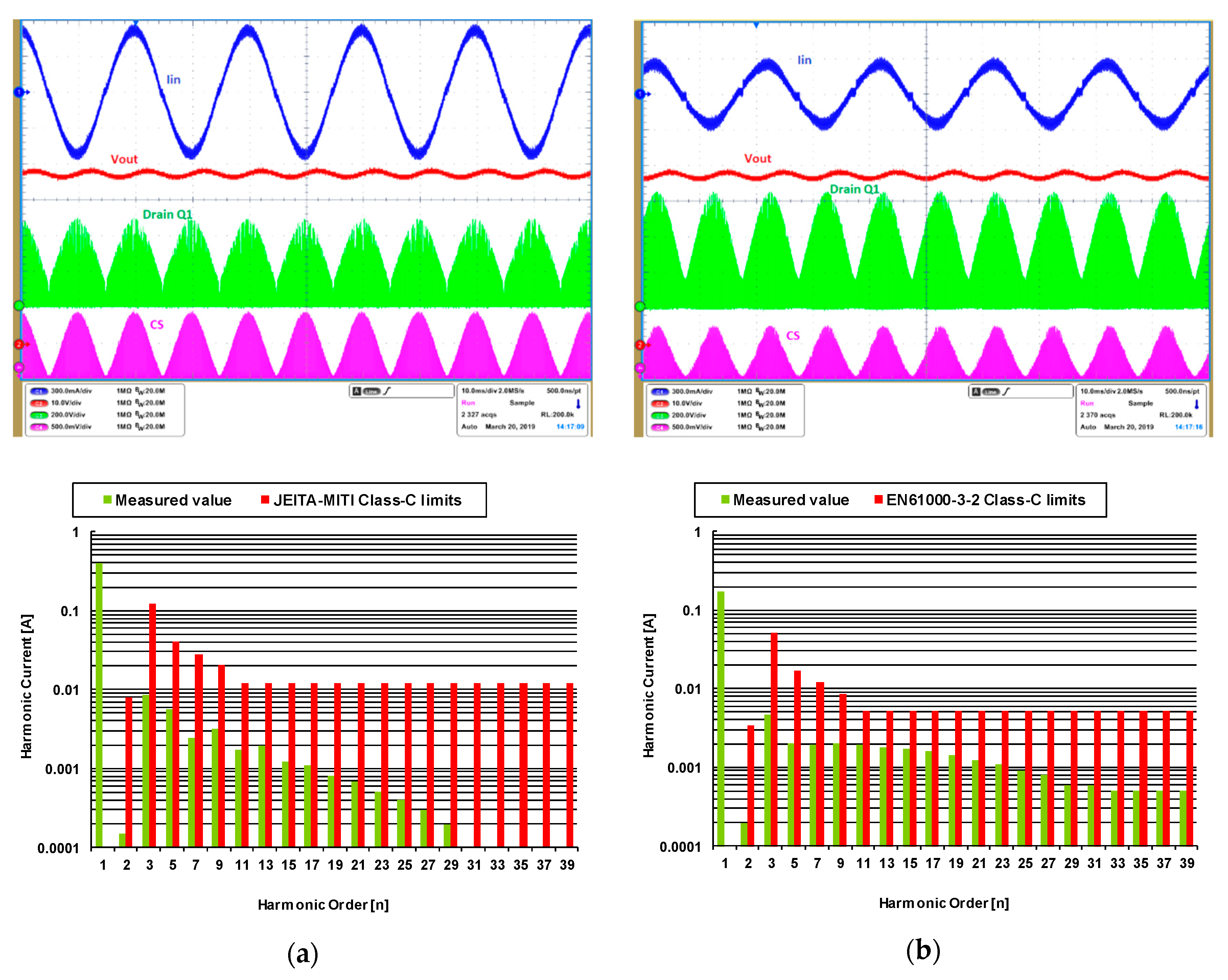
3.2. Experimental Verification of the Input Current Distortion in a Hi-PF QR Flyback LED Driver
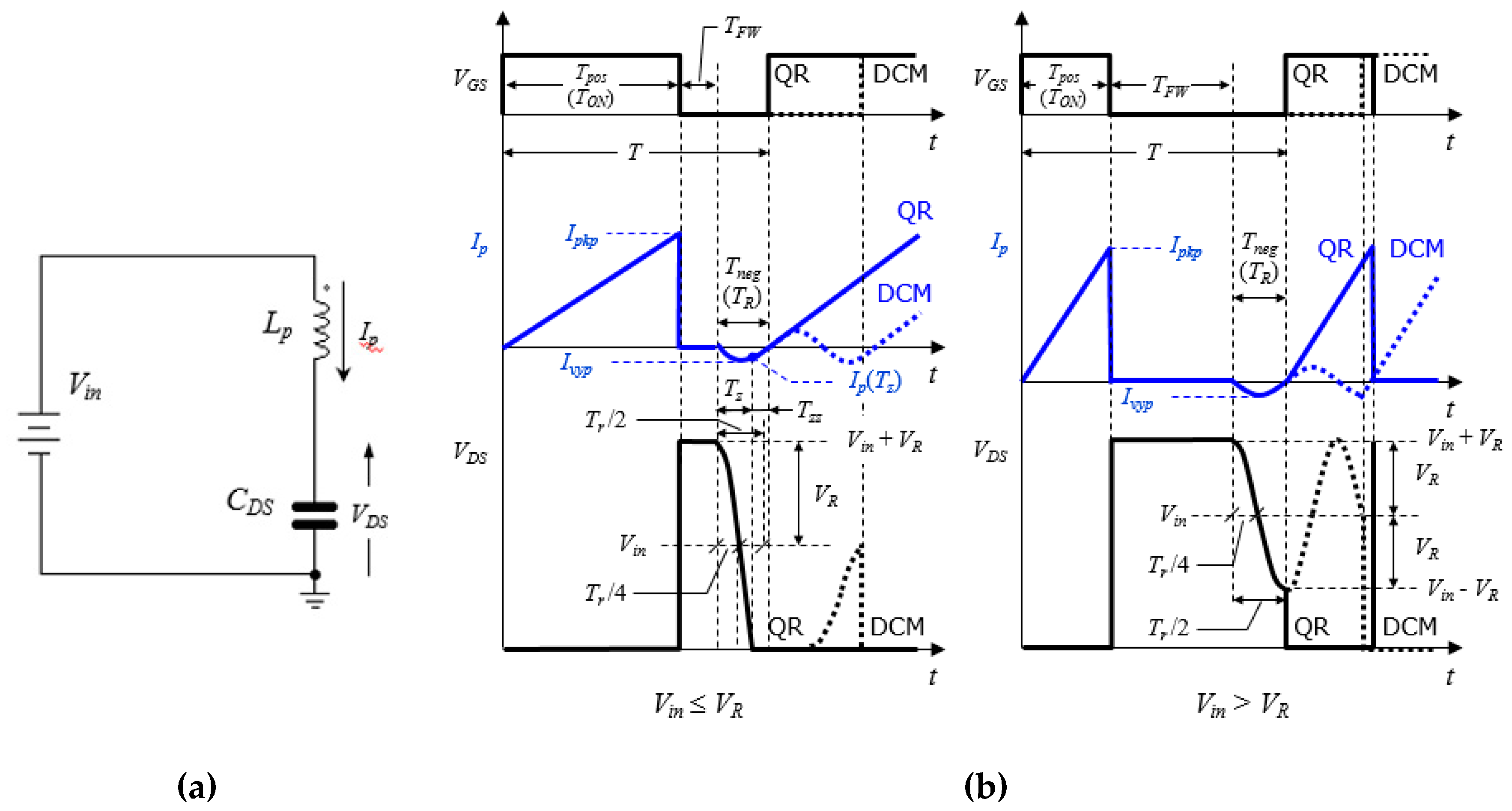
3.3. Distortion Caused by the Ringing Current
- Vin > VR. In the time interval (0, Tneg) VDS(t) is always greater than zero and the current Ip(t) is sinusoidal; Tneg equals half the ringing period. The average value of Ip(t) during Tneg is 2/π times the negative peak value |Ivyp| = YLVR, therefore:
- Vin ≤ VR. The current Ip(t) is sinusoidal in the subinterval (0, Tz). Tz can be expressed as:and the current Ip(t) evaluated when t = Tz is:
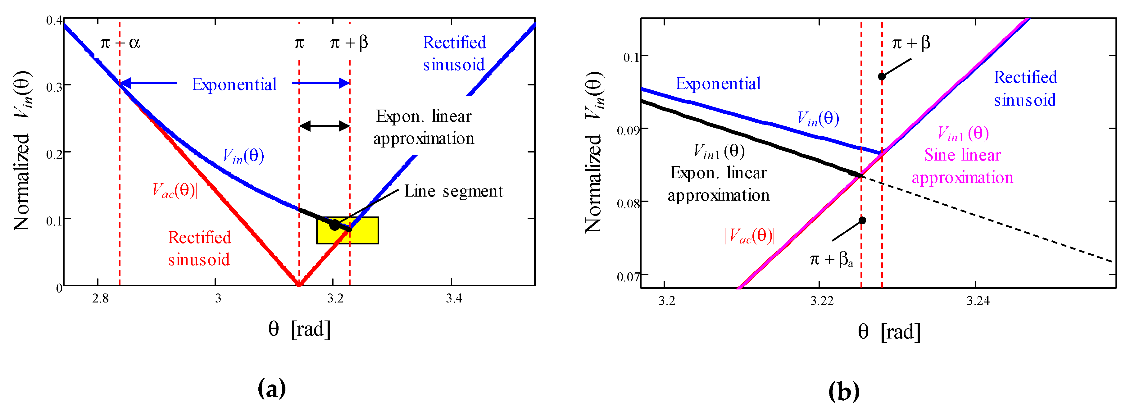
3.4. Crossover Distortion Due to the Input Capacitor
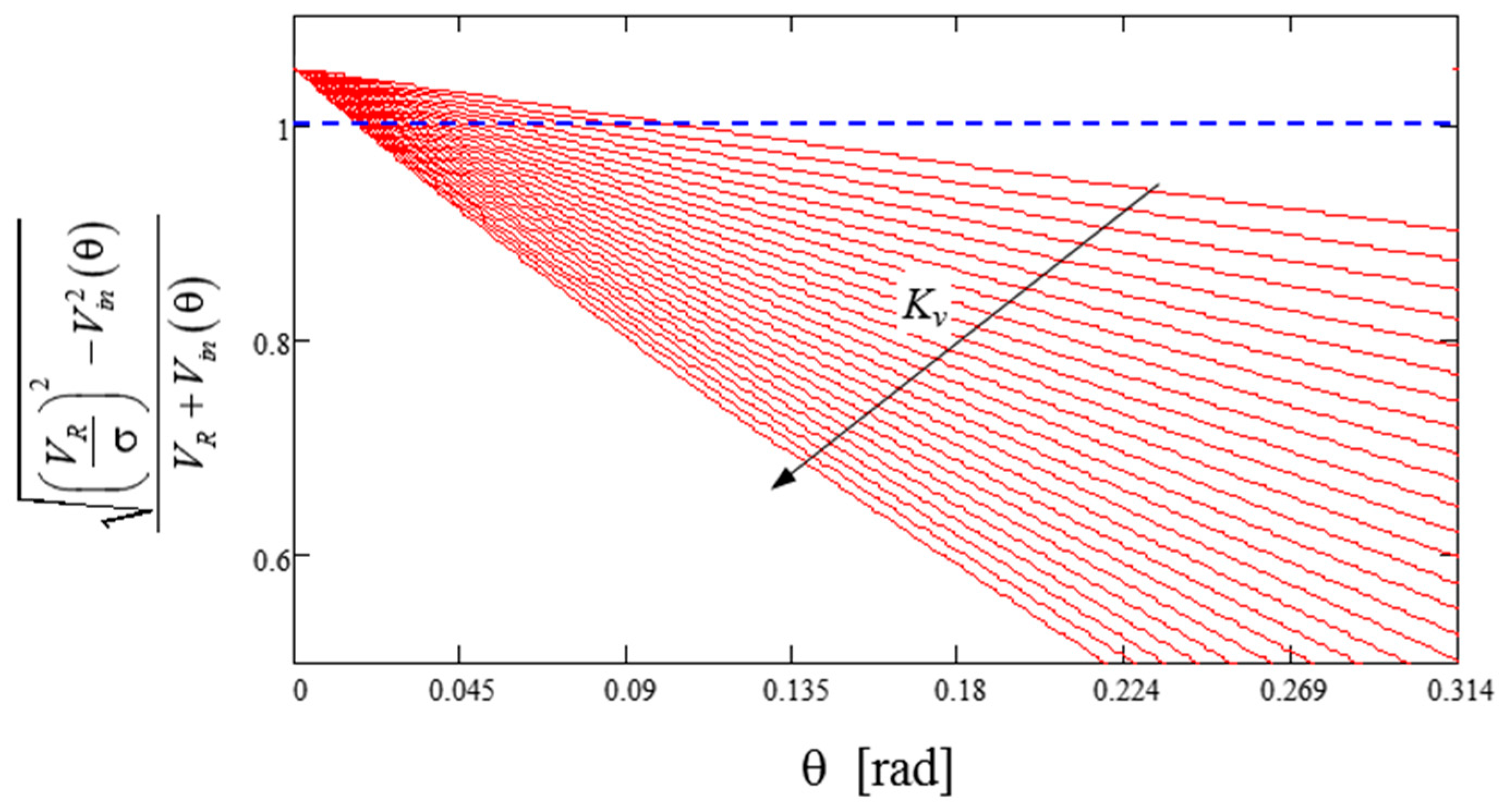
3.5. Crossover Distortion Due to Transformer’s Leakage Inductance
4. Conclusions
- The impact of the ringing current after transformer demagnetization can be mitigated by lowering the switching frequency, using a low reflected voltage VR or choosing a power MOSFET with a RDS(on) with an optimized RDS(on)/Coss FOM. These criteria also help to reduce the phenomenon of the lack of input-to-output energy transfer near the zero crossings of the line voltage.
- The leakage inductance of the transformer should be kept as low as practically possible. This choice essentially optimizes the converter efficiency but does not impact the reduction in the dead zones near the zero crossings of the line voltage caused by other phenomena (essentially, the input capacitor CS).
- The input storage capacitor CS should be minimized to reduce the dead zone near the line voltage zero crossings and the current leap occurring in the proximity of the dead zone. However, particular attention should be paid to the following points.
- The diodes of the input bridge rectifier are usually slow-recovery ones, so the primary current at the switching frequency may require an enhanced filter on the ac side of the bridge and may cause the diodes of the bridge to overheat.
- Close to the zero crossings, the switching frequency can be very low. If the ringing frequency related to CS and Lp is comparable with the switching one, it may generate current spikes that would degrade the current THD.
- Class-X capacitors are generally used along with inductors for EMI filtering, necessary for the certification of the final product. Class-X capacitors can degrade the PF, although they do not contribute to the THD. From this perspective, on the one hand, the design of the filter must make the device compliant with the standards. On the other hand, there is a degree of freedom that can be exploited to minimize PF lowering at high line and light load. The filters should be designed with the largest inductance and the smallest capacitance practically possible.
Author Contributions
Funding
Conflicts of Interest
Nomenclature
| [V] | Line voltage input. | |
| [V] | Rectified line voltage. | |
| [V] | Peak of the rectified line voltage Vin (θ). | |
| [A] | Line input current. | |
| [A] | Current on the primary windings. | |
| [A] | Current on the secondary windings. | |
| [A] | Output constant current. | |
| [V] | Output constant voltage. | |
| [Ω] | Inductance of the primary windings. | |
| [Ω] | Inductance of the secondary windings. | |
| [s] | On time of the power switch | |
| [s] | Time interval where the current flows on the secondary side. | |
| [s] | Time interval where the drain–source voltage rings | |
| [s] | Time interval of the switching period. | |
| [F] | Drain to source capacitance of the MOSFET. | |
| [V] | Drain to source voltage of the MOSFET. | |
| [A] | Current amplitude on the primary windings. | |
| [V] | Reflected voltage. | |
| [s] | Time period of drain voltage ringing. | |
| [s] | Time interval needed for VDS to fall to zero. | |
| [s] | Time interval needed for primary current to ramp linearly until zero. | |
| [Ω] | Characteristic admittance of the CDS-Lp tank circuit. | |
| [C] | Charge accumulates from the input source. | |
| [C] | Charge returned to the input source. | |
| [Ω] | Magnetizing inductance. | |
| [s] | Time interval needed to demagnetize the leakage inductance. | |
| Coupling coefficient of Lm. | ||
| [A] | Current amplitude on the secondary windings. | |
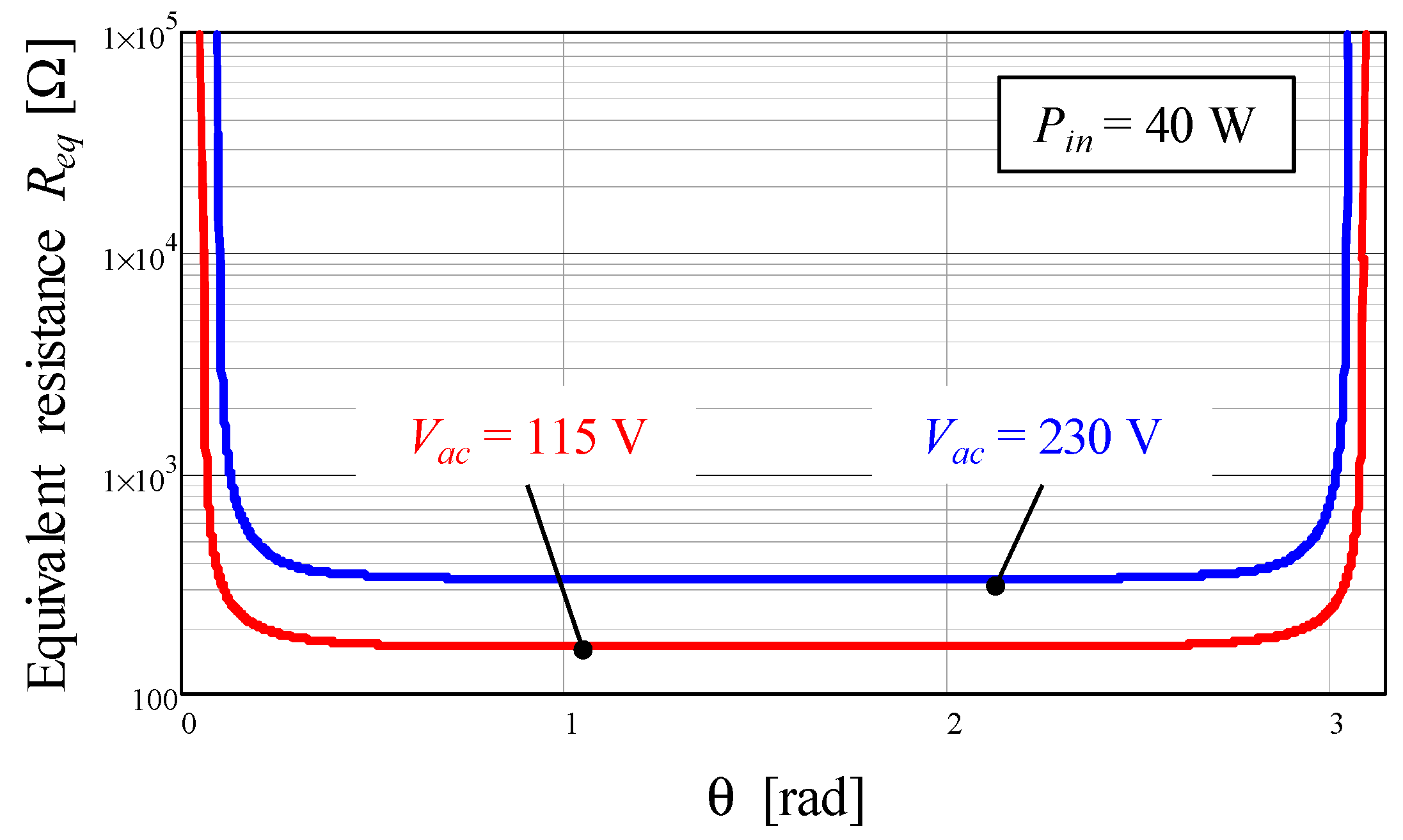
| [Ω] | Equivalent resistor of the converter. | |
| [W] | Input power. |
References
- Shabbir, H.; Ur Rehman, M.; Rehman, S.A.; Sheikh, S.K.; Zaffar, N. Assessment of harmonic pollution by LED lamps in power systems. In Proceedings of the Clemson University Power Systems Conference, Clemson, SC, USA, 11–14 March 2014; pp. 1–7. [Google Scholar]
- Mehta, R.; Deshpande, D.; Kulkarni, K.; Sharma, S.; Divan, D. A Competitive Solution for General Lighting Applications. In Proceedings of the IEEE Energy 2030 Conference, Atlanta, GA, USA, 17–18 November 2008; pp. 1–5. [Google Scholar]
- Moriarty, P.; Honnery, D. Energy policy and economics under climate change. AIMS Energy 2018, 6, 272–290. [Google Scholar] [CrossRef]
- Hsu, Y.-C.; Lin, J.-Y.; Chen, C.C.-P. Area-Saving and High-Efficiency RGB LED Driver with Adaptive Driving Voltage and Energy-Saving Technique. Energies 2018, 11, 1422. [Google Scholar] [CrossRef] [Green Version]
- Ramljak, I.; Amir Tokić, A. Harmonic emission of LED lighting. AIMS Energy 2020, 8, 1–26. [Google Scholar] [CrossRef]
- Nagaraj, C.; Manjunatha Sharma, k. Fuzzy PI controller for bidirectional power flow applications with harmonic current mitigation under unbalanced scenario. AIMS Energy 2018, 6, 695–709. [Google Scholar]
- Lee, E.S.; Nguyen, D.T.; Rim, C.T. A novel passive type LED driver for static LED power regulation by multi-stage switching circuits. In Proceedings of the IEEE Applied Power Electronics Conference and Exposition (APEC), Charlotte, NC, USA, 15–19 March 2015; pp. 900–905. [Google Scholar]
- Wang, Y.; Huang, J.; Shi, G.; Wang, W.; Xu, D. A Single-Stage Single-Switch LED Driver Based on the Integrated SEPIC Circuit and Class-E Converter. IEEE Trans. Power Electron. 2016, 31, 5814–5824. [Google Scholar] [CrossRef]
- Hu, Y.; Huber, L.; Jovanovic, M. Single-Stage Flyback Power-Factor-Correction Front-End for HB LED Application. In Proceedings of the IEEE Industry Applications Society Annual Meeting, Houston, TX, USA, 4–8 October 2009; pp. 1–8. [Google Scholar]
- Maksimovic, D.; Cuk, S. Switching converters with wide DC conversion range. IEEE Trans. Power Electron. 1991, 6, 151–157. [Google Scholar] [CrossRef]
- Huber, L.; Jovanovic, M. Single-stage single-switch input-current-shaping technique with reduced switching loss. IEEE Trans. Power Electron. 2000, 15, 681–687. [Google Scholar] [CrossRef]
- Chiu, H.J.; Cheng, S.J. LED backlight driving system for large-scale LCD panels. IEEE Trans. Ind. Electron. 2007, 54, 2751–2760. [Google Scholar] [CrossRef]
- Nassary, M.; Orabi, M.; Arias, M.; Ahmed, E.M.; Hasaneen, E.-S. Analysis and Control of Electrolytic Capacitor-Less LED Driver Based on Harmonic Injection Technique. Energies 2018, 11, 3030. [Google Scholar] [CrossRef] [Green Version]
- Chiu, H.J.; Song, T.H.; Cheng, S.J.; Li, C.H.; Lo, Y.K. Design and implementation of a single-stage high-frequency HID lamp electronic ballast. IEEE Trans. Ind. Electron. 2008, 55, 674–683. [Google Scholar] [CrossRef]
- Li, Y. A Novel Control Scheme of Quasi-Resonant Valley-Switching for High-Power-Factor AC-to-DC LED Drivers. IEEE Trans. Ind. Electron. 2015, 62, 4787–4794. [Google Scholar] [CrossRef]
- IEEE-1459-2010 Standard—IEEE Standard Definitions for the Measurements of Electric Power Quantities under Sinusoidal, Nonsinusoidal, Balanced or Unbalanced Conditions; IEEE: New York, NY, USA, 2010.
- Chen, W.; Li, S.N.; Hui, S.Y.R. A comparative study on the circuit topologies for offline passive light-emitting diode (LED) drivers with long lifetime & high efficiency. In Proceedings of the 2010 IEEE Energy Conversion Congress and Exposition (ECCE), Atlanta, GA, USA, 12–16 September 2010; pp. 724–730. [Google Scholar]
- Lee, B.; Kim, H.; Rim, C. Robust Passive LED Driver Compatible with Conventional Rapid-Start Ballast. IEEE Trans. Power Electron. 2011, 26, 3694–3706. [Google Scholar] [CrossRef]
- Hui, S.Y.; Li, S.N.; Tao, X.H.; Chen, W.; Ng, W.M. A Novel Passive Offline LED Driver with Long Lifetime. IEEE Trans. Power Electron. 2010, 25, 2665–2672. [Google Scholar] [CrossRef]
- Wang, Y.; Alonso, J.M.; Ruan, X. A Review of LED Drivers and Related Technologies. IEEE Trans. Ind. Electron. 2017, 64, 5754–5765. [Google Scholar] [CrossRef]
- Yada, T.; Katamoto, Y.; Yamada, H.; Tanaka, T.; Okamoto, M.; Hanamoto, T. Design and Experimental Verification of 400-W Class LED Driver with Cooperative Control Method for Two-Parallel Connected DC/DC Converters. Energies 2018, 11, 2237. [Google Scholar] [CrossRef] [Green Version]
- Pinto, R.A.; Cosetin, M.R.; Marchesan, T.B.; Cervi, M.; Campos, A.; Do Prado, R.N. Compact lamp using high-brightness LEDs. In Proceedings of the IEEE Industry Applications Society Annual Meeting, Edmonton, AB, Canada, 5–9 October 2008; pp. 1–5. [Google Scholar]
- Li, Y.Y.-C.; Chen, C.-L.C. A novel single-stage high-power-factor AC-to-DC LED driving circuit with leakage inductance energy recycling. IEEE Trans. Ind. Electron. 2012, 59, 793–802. [Google Scholar] [CrossRef]
- Alonso, J.M.; Vina, J.; Vaquero, D.G.; Martinez, G.; Osorio, R. Analysis and design of the integrated double buck–boost converter as a high-power-factor driver for power-LED lamps. IEEE Trans. Ind. Electron. 2012, 59, 1689–1697. [Google Scholar] [CrossRef]
- Qu, X.; Wong, S.C.; Tse, C.K. Resonance-assisted buck converter for offline driving of power LED replacement lamps. IEEE Trans. Power Electron. 2011, 26, 532–540. [Google Scholar]
- Qin, Y.; Chung, H.; Lin, D.Y.; Hui, S.Y.R. Current source ballast for high power lighting emitting diodes without electrolytic capacitor. In Proceedings of the 34th Annual Conference of IEEE Industrial Electronics, Orlando, FL, USA, 10–13 November 2008; pp. 1968–1973. [Google Scholar]
- Hwu, K.-I.; Tai, Y.-K.; He, Y.-P. Bridgeless Buck-Boost PFC Rectifier with Positive Output Voltage. Appl. Sci. 2019, 9, 3483. [Google Scholar] [CrossRef] [Green Version]
- Ma, H.; Lai, J.; Feng, Q.; Yu, W.; Zheng, C.; Zhao, Z. A Novel Valley-Fill SEPIC-Derived Power Supply without Electrolytic Capacitor for LED Lighting Application. IEEE Trans. Power Electron. 2012, 27, 3057–3071. [Google Scholar] [CrossRef]
- Hariprasath, S.; Balamurugan, R. A valley-fill SEPIC-derived power factor correction topology for LED lighting applications using one cycle control technique. In Proceedings of the International Conference on Computer Communication and Informatics, Coimbatore, India, 4–6 January 2013; pp. 1–4. [Google Scholar]
- Wu, X.; Wang, Z.; Zhang, J. Design Considerations for Dual-Output Quasi-Resonant Flyback LED Driver with Current-Sharing Transformer. IEEE Trans. Power Electron. 2013, 28, 4820–4830. [Google Scholar] [CrossRef]
- Shagerdmootaab, A.; Moallem, M. Filter Capacitor Minimization in a Flyback LED Driver Considering Input Current Harmonics and Light Flicker Characteristics. IEEE Trans. Power Electron. 2015, 30, 4467–4476. [Google Scholar] [CrossRef]
- Arias, M.; Lamar, D.G.; Linera, F.F.; Balocco, D.; Aguissa Diallo, A.; Sebastián, J. Design of a Soft-Switching Asymmetrical Half-Bridge Converter as Second Stage of an LED Driver for Street Lighting Application. IEEE Trans. Power Electron. 2012, 27, 1608–1621. [Google Scholar] [CrossRef]
- Kim, C.; Kim, E.; Shin, H. A study on the power LEDs drive circuit design with asymmetrical half-bridge resonant converter. In Proceedings of the International Conference on Electrical Machines and Systems, Tokyo, Japan, 15–18 November 2009; pp. 1–4. [Google Scholar]
- Arias, M.; Diaz, M.F.; Cadierno, J.E.R.; Lamar, D.G.; Sebastián, J. Digital Implementation of the Feedforward Loop of the Asymmetrical Half-Bridge Converter for LED Lighting Applications. IEEE J. Emerg. Sel. Top. Power Electron. 2015, 3, 642–653. [Google Scholar] [CrossRef] [Green Version]
- Castro, I.; Martin, K.; Vazquez, A.; Arias, M.; Lamar, D.G.; Sebastian, J. An AC–DC PFC Single-Stage Dual Inductor Current-Fed Push–Pull for HB-LED Lighting Applications. IEEE J. Emerg. Sel. Top. Power Electron. 2018, 6, 255–266. [Google Scholar] [CrossRef] [Green Version]
- Mohamadi, A.; Afjei, E. A single-stage high power factor LED driver in continuous conduction mode. In Proceedings of the 6th Power Electronics, Drive Systems & Technologies Conference (PEDSTC2015), Tehran, Iran, 3–4 February 2015; pp. 462–467. [Google Scholar]
- Wang, L.; Zhang, B.; Qiu, D. A Novel Valley-Fill Single-Stage Boost-Forward Converter with Optimized Performance in Universal-Line Range for Dimmable LED Lighting. IEEE Trans. Ind. Electron. 2017, 64, 2770–2778. [Google Scholar] [CrossRef]
- Chen, S.-M.; Liang, T.-J.; Yang, L.-S.; Chen, J.-F. A safety enhanced, high step-up DC-DC converter for AC photovoltaic module application. IEEE Trans. Power Electron. 2012, 27, 1809–1817. [Google Scholar] [CrossRef]
- Cheng, C.; Chang, C.; Cheng, H.; Tseng, C. A novel single-stage LED driver with coupled inductors and interleaved PFC. In Proceedings of the 9th International Conference on Power Electronics and ECCE Asia (ICPE-ECCE Asia), Seoul, Korea, 1–5 June 2015; pp. 1240–1245. [Google Scholar]
- Cheng, C.; Cheng, H.; Chung, T. A novel single-stage high-power-factor LED street-lighting driver with coupled inductors. In Proceedings of the IEEE Industry Applications Society Annual Meeting, Lake Buena Vista, FL, USA, 6–11 October 2013; pp. 1–7. [Google Scholar]
- Duan, R.-Y.; Lee, J.-D. High-efficiency bidirectional DC-DC converter with coupled inductor. IET Power Electron. 2012, 5, 115–123. [Google Scholar] [CrossRef]
- Vecchia, M.D.; Van den Broeck, G.; Ravyts, S.; Tant, J.; Driesen, J. Modified step-down series-capacitor buck converter with insertion of a Valley-Fill structure. IET Power Electron. 2019, 12, 3306–3314. [Google Scholar] [CrossRef]
- Xu, S.; Shen, W.; Qian, Q.; Zhu, J.; Sun, W.; Li, H. An efficiency optimization method for a high frequency quasi-ZVS controlled resonant flyback converter. In Proceedings of the IEEE Applied Power Electronics Conference and Exposition (APEC), Anaheim, CA, USA, 17–21 March 2019; pp. 2957–2961. [Google Scholar]
- Tabisz, W.A.; Gradzki, P.M.; Lee, F.C.Y. Zero-voltage-switched quasi-resonant buck and flyback converters-experimental results at 10 MHz. IEEE Trans. Power Electron. 1989, 4, 194–204. [Google Scholar] [CrossRef]
- Gritti, G.; Adragna, C. Analysis, design and performance evaluation of an LED driver with unity power factor and constant-current primary sensing regulation. AIMS Energy 2019, 7, 579–599. [Google Scholar] [CrossRef]
- Zhang, S.; Liu, X.; Guan, Y.; Yao, Y.; Alonso, J.M. Modified zero-voltage-switching single-stage LED driver based on Class E converter with constant frequency control method. IET Power Electron. 2018, 11, 2010. [Google Scholar] [CrossRef]
- Jeng, L.S.; Peng, T.M.; Hsu, Y.C.; Chieng, H.W.; Shu, J.P. Quasi-Resonant Flyback DC/DC Converter Using GaN Power Transistors. World Electr. Veh. J. 2012, 5, 567–573. [Google Scholar] [CrossRef] [Green Version]
- Xie, X.; Li, J.; Peng, K.; Zhao, C.; Lu, Q. Study on the Single-Stage Forward-Flyback PFC Converter With QR Control. IEEE Trans. Power Electron. 2016, 31, 430–442. [Google Scholar] [CrossRef]
- Wang, Z.; Wu, X.; Chen, M.; Zhang, J. Optimal design methodology for the current-sharing transformer in a quasi-resonant (QR) flyback LED driver. In Proceedings of the Twenty-Seventh Annual IEEE Applied Power Electronics Conference and Exposition (APEC), Orlando, FL, USA, 5–9 February 2012; pp. 2372–2378. [Google Scholar]
- Li, J.; Liang, T.; Chen, K.; Lu, Y.; Li, J. Primary-side controller IC design for quasi-resonant flyback LED driver. In Proceedings of the IEEE Energy Conversion Congress and Exposition (ECCE), Montreal, QC, Canada, 20–24 September 2015; pp. 5308–5315. [Google Scholar]
- Zhang, J.; Zeng, H.L.; Wu, X.K. An Adaptive Blanking Time Control Scheme for an Audible Noise-Free Quasi-Resonant Flyback Converter. IEEE Trans. Power Electron. 2011, 26, 2735–2742. [Google Scholar] [CrossRef]
- Chen, K.; Chiu, C.C.; Lin, M.; Yeh, C.P.; Lin, J.M.; Chen, K.H. Quasi-Resonant Control with Dynamic Frequency Selector and Constant Current Startup Technique for 92% Peak Efficiency and 85% Light-load Efficiency Flyback Converter. IEEE Trans. Power Electron. 2013, 29, 4959–4969. [Google Scholar]
- Ringel, M.; Schlomann, B.; Krail, M.; Rohde, C. Towards a green economy in Germany? The role of energy efficiency policies. Appl. Energy 2016, 179, 1293–1303. [Google Scholar] [CrossRef]
- Erickson, R.; Madigan, M.; Singer, S. Design of a simple high-power-factor rectifier based on the flyback converter. In Proceedings of the Fifth Annual Proceedings on Applied Power Electronics Conference and Exposition, Los Angeles, CA, USA, 11–16 March 1990; pp. 792–801. [Google Scholar]
- Huber, L.; Irving, B.T.; Jovanovic, M.M. Line current distortions of DCM/CCM boundary boost PFC converter. In Proceedings of the Twenty-Third Annual IEEE Applied Power Electronics Conference and Exposition, Austin, TX, USA, 24–28 February 2008; pp. 702–708. [Google Scholar]
- Kim, J.W.; Choi, S.M.; Kim, K.T. Variable On-time Control of the Critical Conduction Mode Boost Power Factor Correction Converter to Improve Zero-crossing Distortion. In Proceedings of the International Conference on Power Electronics and Drives Systems, Kuala Lumpur, Malaysia, 28 November–1 December 2005; pp. 1542–1546. [Google Scholar]
- Guo, Z.; Ren, X.; Wu, Y.; Zhang, Z.; Chen, Q. A novel simplified variable on-time method for CRM boost PFC converter. In Proceedings of the IEEE Applied Power Electronics Conference and Exposition (APEC), Tampa, FL, USA, 26–30 March 2017; pp. 1778–1784. [Google Scholar]


| Parameter | Value |
|---|---|
| Input voltage range [Vac] | 90–265 V |
| Line frequency range [fl] | 47–63 Hz |
| Rated output voltage [Vout] | 48 V |
| Regulated dc output current [Iout] | 700 mA |
| Expected full-load efficiency [η] | 86% |
| Transformer primary inductance [Lp] | 500 μH |
| Reflected voltage [VR] | 120 V |
| Drain–Source capacitance [CDS] | 150 pF |
© 2020 by the authors. Licensee MDPI, Basel, Switzerland. This article is an open access article distributed under the terms and conditions of the Creative Commons Attribution (CC BY) license (http://creativecommons.org/licenses/by/4.0/).
Share and Cite
Adragna, C.; Gritti, G.; Raciti, A.; Rizzo, S.A.; Susinni, G. Analysis of the Input Current Distortion and Guidelines for Designing High Power Factor Quasi-Resonant Flyback LED Drivers. Energies 2020, 13, 2989. https://doi.org/10.3390/en13112989
Adragna C, Gritti G, Raciti A, Rizzo SA, Susinni G. Analysis of the Input Current Distortion and Guidelines for Designing High Power Factor Quasi-Resonant Flyback LED Drivers. Energies. 2020; 13(11):2989. https://doi.org/10.3390/en13112989
Chicago/Turabian StyleAdragna, Claudio, Giovanni Gritti, Angelo Raciti, Santi Agatino Rizzo, and Giovanni Susinni. 2020. "Analysis of the Input Current Distortion and Guidelines for Designing High Power Factor Quasi-Resonant Flyback LED Drivers" Energies 13, no. 11: 2989. https://doi.org/10.3390/en13112989