Article

Altered Grey Wolf Optimization and Taguchi Method with FEA for Six-Phase Copper Squirrel Cage Rotor Induction Motor Design

Department of Electrical Engineering, National United University, Miaoli 360, Taiwan
Energies 2020, 13(9), 2282; https://doi.org/10.3390/en13092282
Submission received: 12 March 2020 / Revised: 22 April 2020 / Accepted: 22 April 2020 / Published: 5 May 2020
(This article belongs to the Special Issue Design and Analysis of Electric Machines)

Abstract

:
This paper presents an altered grey wolf optimization, the Taguchi method, and finite element analysis (FEA) with two-phase multi-objective optimization for the design of a six-phase copper squirrel cage rotor induction motor (SCSCRIM). The multi-objective optimization design with high-performance property aims to achieve lower starting current, lower losses, lower input power, higher efficiency, higher output torque, and higher power factor. The multi-objective optimization design with high-performance property using the altered grey wolf optimization, the Taguchi method, and FEA in the first-phase program is used for minimizing the starting current, stator iron loss, stator copper loss, and input power. The multi-objective optimization design with high-performance property using the altered grey wolf optimization, the Taguchi method, and FEA in the second-phase program is used for maximizing the efficiency, output torque, and power factor. Finally, the proposed skill with higher performances is evaluated and verified via a two-phase program design and some performance tests.

1. Introduction

Six-phase induction motors [1,2,3] have been used in many domains of electrical power plants, consumer markets, and so on. The six-phase induction motor provides lower torque ripple, better reliability, and higher efficiency for its size compared to the traditional three-phase induction motor [4]. Therefore, there are many optimal design methods and applications for aluminum rotor induction motors [5,6] and copper squirrel cage rotor induction motors [7,8,9,10,11,12,13]. Cunkas et al. [5] proposed an optimal design method to optimize the three-phase aluminum squirrel cage rotor induction motor for optimization of torque, efficiency, and cost by using a genetic algorithm. Sun et al. [6] proposed a bearingless induction motor design with an outer rotor and applied this design in flywheel energy storage systems. Parasiliti and Villani [7] proposed the use of a copper cage in three-phase low-voltage induction motors and a design guideline to optimize efficiency according to the new European classification scheme. Daut et al. [8] investigated the efficiency of a die-cast copper rotor cage induction motor with a H10 non-grain oriented electrical steel sheet as lamination. Kane [9] proposed the use of a copper cage rotor induction motor with higher torque for assisting in engine cranking and peak power mode. Zhang et al. [10] proposed the design and evaluation of a die-cast copper squirrel cage rotor induction motor applied in traction drive by using a 2D finite element model. Moreover, technologies using multi-objective optimization design [11,12,13] are fashionable design skills in a lot of industrial appliances. Mittelstedt et al. [11] proposed optimal designs of composite multi-rim flywheel rotors by using the multi-objective optimization skill. Anwar et al. [12] proposed hybrid bio-inspired meta-heuristic multi-objective optimization in a cloud computing environment by using the optimized multi-objective scheduling of scientific workflows. Shen et al. [13] proposed the optimization of a forecasting model by using an improved multi-objective artificial bee colony algorithm combining multi-objective evolutionary knowledge. However, these multi-objective optimization designs [11,12,13] combined with the other optimized skills resulted in slower convergent speed because of taking more search time to find optimum values.
The Pareto frontier [14,15,16], that is, one of the fashionable frontiers such as the Pareto front or Pareto set, belongs to the set of total Pareto efficient assignments. A Pareto reform is an alteration to a different allocation that makes at least one individual or preference criterion better off without making any other individual or preference criterion worse off, given a certain initial allocation of goods among a set of individuals. When no further Pareto reforms can be made, Pareto optimization is assumed to be achieved. Additionally, one of the fashionable design skills among electromagnetic devices is the use of the finite element method (FEM) [17,18] combined with optimization algorithms. Because the Pareto optimization coupled with FEM takes more calculation time, it is not very efficacious.
Multi-objective grey wolf optimization was proposed by Emary et al. [19] and applied in attribute reduction of systems. Mosavi et al. [20] proposed a sonar dataset category using a feedforward neural network training method and the grey wolf algorithm. Even though the algorithm is very competitive and has been used in various fields [21,22,23], it has poor exploration capability and suffers from local optima stagnation. So, in order to improve the explorative abilities of grey wolf optimization, an altered grey wolf optimization with an adjusted factor is proposed in this paper. Therefore, the main objective of this study is the multi-objective optimization design of a high-performance six-phase copper squirrel cage rotor induction motor (SCSCRIM) by using an altered grey wolf optimization algorithm, the Taguchi method [2,3,24,25] and finite element analysis (FEA) [26,27] to reduce the computing time and enhance the searching speed of optimization. The adopted technology is a very efficient and valid skill in the sturdy design of a high-performance SCSCRIM.

2. Initial Specification and Configuration of SCSCRIM

The initial specifications of the SCSCRIM are six phases, two poles, 3476 r/min and 5 kW; this is described to explain the two-phase high-performance program of the SCSCRIM in this paper. A general structural view of the SCSCRIM is shown in Figure 1. The formatted parameters of the SCSCRIM are given in Table 1. The initial design of the SCSCRIM is based on computerized design programs as follows.
The layout of the windings in the motor affects not only the magnetomotive force (MMF) distribution and the motor performance, but also the torque ripple reduction using the proposed skill. In practice, the motor’s windings are formed by wire-wound coils of one or more turns placed in slots arranged to form either single-layer or double-layer windings [24]. The double-layer windings [24] through six-phase currents can result in a better sinusoidal back electromotive force (EMF) waveform than the single-layer windings [24]. The double-layer winding design with regard to the fundamental winding factor that adopts lap windings and concentric windings is used in this paper. The fundamental winding factor is 0.942 for lap windings and 0.932 for concentric windings in the template test. The fundamental winding factor thus adopts 0.942 for lap windings to raise the back electromotive force in this paper. The induced back EMF from double-layer windings with 0.942 for lap windings results in a better sinusoidal waveform so that the vibrated noise will be obviously cut down.

3. High-Performance Design of SCSCRIM with Multi-Objective Optimization Method

To achieve the high-performance design of the SCSCRIM, the multi-objective optimization method is described as follows. The ordinary minimum function by using multi-objective optimization can be represented by
min x 1 X 1 ,   i = 1 , , k   s 1 ( w i ( x 1 ) ) = s 1 ( w 1 ( x 1 ) , w 2 ( x 1 ) , , w k ( x 1 ) ) s u b j e c t   t o           w i , l b o u n d ( x 1 ) w i ( x 1 ) w i , u b o u n d ( x 1 ) ,       i = 1 , ,   k
where k is equal to four; w 1 ( x 1 ) , w 2 ( x 1 ) , w 3 ( x 1 ) and w 4 ( x 1 ) represent the function of minimizing the stator iron loss, the function of minimizing the stator winding copper loss, the function of minimizing the starting current, and the function of minimizing the input power, respectively; w i , l b o u n d ( x 1 ) and w i , u b o u n d ( x 1 ) represent the lower bound and the upper bound for the stator iron loss, the stator winding copper loss, the starting current, and the input power, respectively.
The ordinary maximum function by using multi-objective optimization can be represented by
max x 2 X 2 ,   j = 1 , , l   s 2 ( v j ( x ) ) = s 2 ( v 1 ( x 2 ) , v 2 ( x 2 ) , , v l ( x 2 ) ) s u b j e c t   t o         v j , l b o u n d ( x 1 ) v j ( x 1 ) v j , u b o u n d ( x 1 ) ,       j = 1 , ,   l
where l is equal to three; v 1 ( x 1 ) , v 2 ( x 1 ) and v 3 ( x 1 ) denote the function of maximizing the efficiency, the function of maximizing the power factor, and the function of maximizing the output torque, respectively; v j , l b o u n d ( x 2 ) and v j , u b o u n d ( x 2 ) represent the lower bound and the upper bound for the efficiency, the power factor, and the output torque, respectively. Two sets X 1 and X 2 are the realistic sets of decision vectors. The realistic sets are generally defined by certain constraint functions. Furthermore, the real-value vector objective functions are defined by w : X 1 Y 1 k ,   w ( x ) = ( w 1 ( x 1 ) , w 2 ( x 1 ) , , w k ( x 1 ) ) T and v : X 2 Y 2 l ,   v ( x ) = ( v 1 ( x 2 ) , v 2 ( x 2 ) , , v l ( x 2 ) ) T . The images of X 1 and X 2 are denoted by Y 1 k and Y 2 l . The elements x 1 * X 1 and x 2 * X 2 are two realistic solutions. The Pareto frontier [14,15,16] is the set of selections that optimizes a system. With all of the latent optimization solutions in the initial condition, the user can make concentrated tradeoffs within this constrained set of parameters, rather than needing to premeditate the full areas of parameters. Additionally, the Pareto front is the solution space, which is not a plane.
Moreover, altered grey wolf optimization is proposed to search for optimal values. The altered grey wolf optimization is conducted by alpha, beta, and delta. The altered grey wolf optimization can be represented by
Q ( l 1 + 1 ) = [ Q 1 ( l 1 ) + Q 2 ( l 1 ) + Q 3 ( l 1 ) ] / 3
where Q ( l 1 + 1 ) is a vector that makes up the optimal parameters, and Q 1 ( l 1 ) ,   Q 2 ( l 1 ) , Q 3 ( l 1 ) are represented by
Q 1 ( l 1 ) = | Q α ( l 1 ) E 1 ( l 1 ) [ H 1 ( l 1 ) Q α ( l 1 ) Q ( l 1 ) ] |
Q 2 ( l 1 ) = | Q β ( l 1 ) E 2 ( l 1 ) [ H 2 ( l 1 ) Q β ( l 1 ) Q ( l 1 ) ] |
Q 3 ( l 1 ) = | Q δ ( l 1 ) E 3 ( l 1 ) [ H 3 ( l 1 ) Q δ ( l 1 ) Q ( l 1 ) ] |
where Q α ( l 1 ) ,   Q β ( l 1 ) , Q δ ( l 1 ) are the three vectors with the three best solutions; E 1 ( l 1 ) ,   E 2 ( l 1 ) ,   E 3 ( l 1 ) and H 1 ( l 1 ) ,   H 2 ( l 1 ) ,   H 3 ( l 1 ) are represented by
E 1 ( l 1 ) = E 2 ( l 1 ) = E 3 ( l 1 ) = [ 2 c 1 ( l 1 ) d 1 ( l 1 ) ] φ 1
H 1 ( l 1 ) = H 2 ( l 1 ) = H 3 ( l 1 ) = 2 φ 2
where φ 1 and φ 2 are two random vectors. The updated numbers of the two factors c 1 ( l 1 ) and d 1 ( l 1 ) control the tradeoff between exploration and exploitation. The two updated factors c 1 ( l 1 ) and d 1 ( l 1 ) are linearly updated at each iteration according to the following presentation, by
c 1 ( l 1 ) = 2 2 l 1 / I i 1
d 1 ( l 1 ) = 2 2 l 1 / I i 2
where l 1 is the iteration number; I i 1 and I i 2 are the total numbers of iteration allowed for the optimization. Finally, Q ( l 1 + 1 ) is the best solution with regard to the search for the parameter. Hence, numbers can be optimized by using altered grey wolf optimization.
Two main origins of losses in alter current (AC) motors are iron losses and copper losses. Iron losses are the major losses in the parts that conduct variable flux-linkage with time. Two mechanisms of iron loss are hysteresis and eddy current losses. Copper losses are caused by current flowing via the resistance of any windings. Copper losses can be decreased as follows: (1) reducing resistance, (2) increasing the cross-sectional area of conductors, (3) lowering the winding temperature, (4) using materials that have lower resistivity. Copper conductor materials with increasing current densities can be accomplished to reduce extra losses. Both of these increase with increasing flux density in the teeth and back iron. Hysteresis losses are related to the electrical frequency. Eddy current losses are related to the square of the electrical frequency. The performances of induction motors are deeply affected by some losses in their stators and rotors. To apply the altered grey wolf optimization skill, an objective function has to be defined to evaluate the SCSCRIM design with good performance. This objective function may include all the geometric dimensions of the motor, and a large subset of constraints have to be formulated to ensure the physical realization of the SCSCRIM. These objective functions are given in the following. The first objective function aims to minimize the stator iron loss. The stator iron loss variable consists of the laminations, which are used as the objective function of the optimization. The stator iron loss W s i l can be indicated by [28,29,30]
W s i l = k 1 f m B m 2 + k 2 f m 2 B m 2
where W s i l is the iron loss, k 1 is the scale coefficients of the hysteresis loss, k 2 is the scale coefficients of the eddy current loss, f m is the frequency of the flux field, and B m is the value of the maximum flux density.
The stator copper loss W s c l of the stator copper winding can be represented by [28,29,30]
W s c l = I s 2 ρ s N s 1 M s 2 L s / A s
where I s denotes the root-mean-square current through the stator copper conductor, ρ s denotes the resistivity of the stator copper conductor, N s 1 denotes the number of stator slots, M s 2 denotes the number of stator conductors per stator slot, L s denotes the length per stator copper conductor per stator slot, and A s denotes the cross-section per stator copper conductor per stator slot.
The rotor copper loss W r c l of the rotor copper winding can be represented by [28,29,30]
W r c l = I r 2 ρ r N r 1 M r 2 L r / A r
where I r denotes the root-mean-square (RMS) current through the rotor copper conductor, ρ r denotes the resistivity of the rotor copper conductor, N r 1 denotes the number of rotor slots, M r 2 denotes the number of rotor conductors per rotor slot, L r denotes the length per rotor copper conductor per rotor slot, and A r denotes the cross-section per rotor copper conductor per rotor slot.
The input power P i m can be represented by
P i m = 6   V p h I p h cos θ p h
where I p h is the phase current, V p h is the phase voltage, and cos θ p h is the power factor per phase.
Then, the objective function aims to maximize the efficiency η m , the power factor P F m , and the output torque T o m . The efficiency η m can be denoted by
η m = ( P o m / P i m ) × 100 %
where P o m denotes the output power of the motor, and P i m denotes the input power of the motor, respectively.
The power factor P F m = cos θ p h can be denoted by
P F m = cos θ p h = ( P i m / S i m ) %
where S i m denotes the input apparent power of the motor.
The output torque T o m can be denoted by
T o m = ( P o m / ω m ) %
where ω m denotes the rotor speed.

4. Programs of High-Performance Design

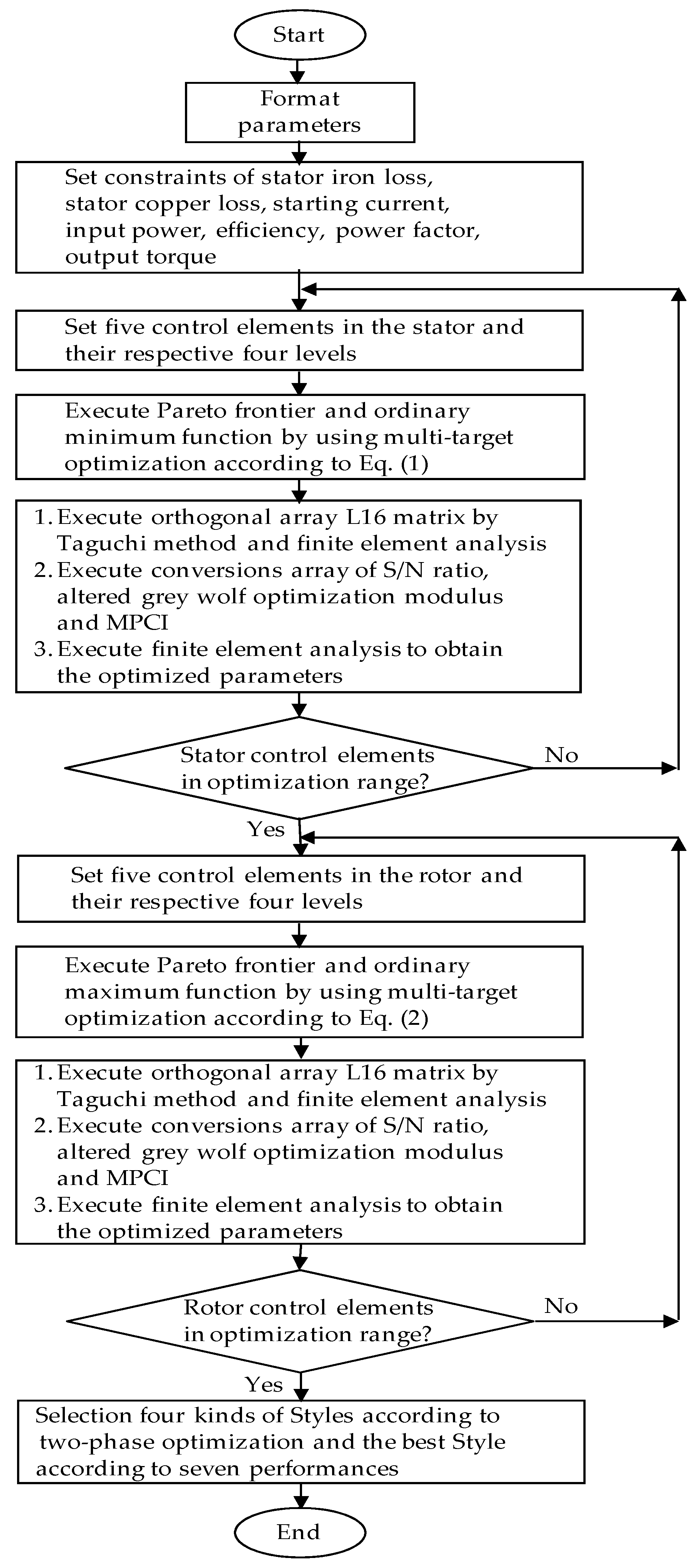
This paper presents the two-phase high-performance design of a SCSCRIM with multi-objective optimization by use of two kinds of optimization skills, which depend on the stator and rotor areas. This design procedure is applicable only to a SCSCRIM. A flow chart of the optimization procedure with two-phase multi-objective optimization for SCSCRIM design is shown in Figure 2. The description of the optimization procedure is as follows.

4.1. The First-Phase Program

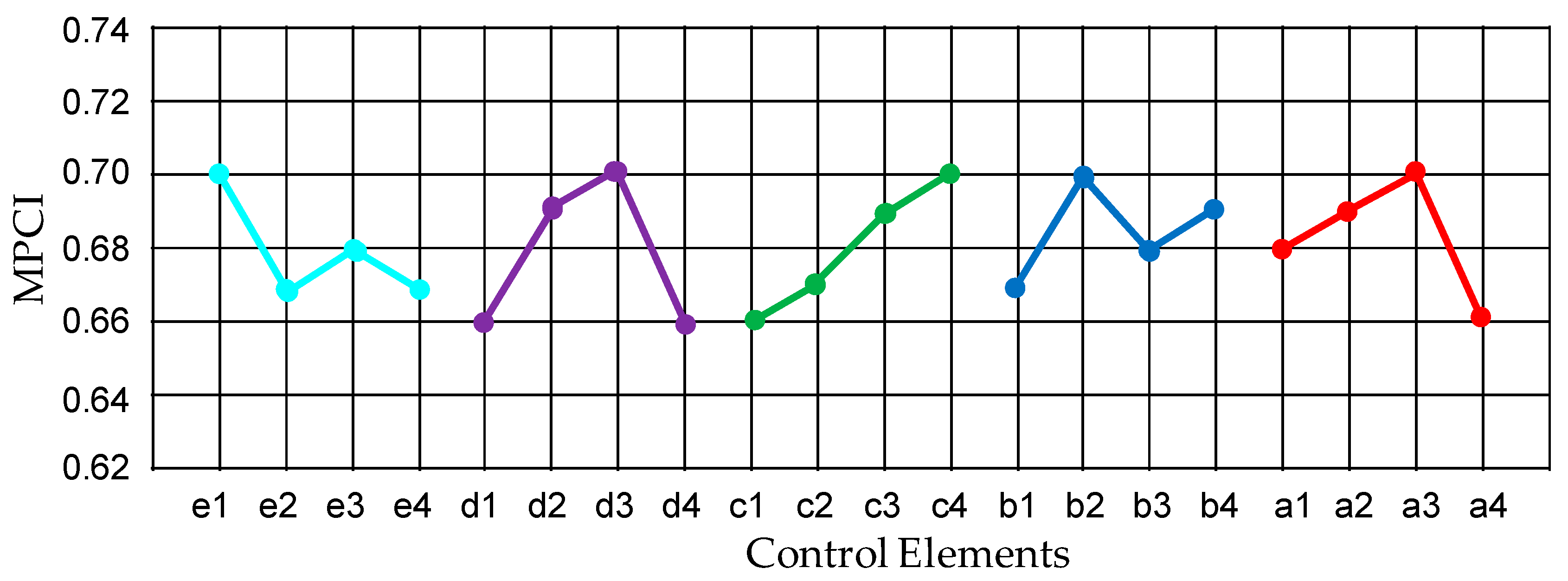
The high-performance design with multi-objective optimization in the first-phase program aims to minimize the stator copper loss, stator iron loss, starting current, and input power using Equation (1). In order to quickly search for the optimal value, the Taguchi method [2,3,24,25] is adopted to optimize the machine parameter of performance characteristics in electrical discharge machining. The orthogonal array in designs played an important role in the development of the Taguchi method. The performance tests by use of the standard Taguchi method with an orthogonal array L16 matrix are shown in Table 2. Then, the performance tests by use of the standard Taguchi method with an orthogonal array L16 matrix from Table 2 are transformed into a signal-to-noise (S/N) ratio. The S/N ratio is used to measure the deviation of the shown characteristics from the desired values. There are three categories of performance characteristics in the analysis of the S/N ratio: the lower the better, the higher the better, and the nominal the better [24]. Furthermore, the performance tests by use of the standard Taguchi method with an orthogonal array L16 matrix from Table 2 are transformed into the S/N ratios and the altered grey wolf optimization modulus based on altered grey wolf optimization analysis [19,20,21] as shown in Table 3. Therefore, the optimal level of the process parameters is the level with the lowest S/N ratio. Meanwhile, the machine performance with the multiple performance characteristics index (MPCI) [24,25] in the standard Taguchi method with an orthogonal array L16 matrix can be obtained by use of FEA [26,27] with regard to complementary numerical results as shown in Table 3. To execute the optimization process, five stator geometrical parameters that affect the machine performance are chosen as shown in Figure 3. The elements and their respective levels are given in Table 2, where A is the stator tooth width in mm (levels 5.5, 6.0, 6.5 and 7.0), B is the stator slot height in mm (levels 20.8, 21.8, 22.8 and 23.8), C is the stator boot width in mm (levels 3.8, 4.0, 4.2 and 4.4), D is the stator slot opening width in mm (levels 2.5, 2.8, 3.1 and 3.4), and E is the winding length per stator slot in mm (levels 92, 94, 96 and 98). These elements are related to stator iron loss, stator copper loss, starting current, and input power because of flux action in the stator. The S/N ratio is used to determine the deviation between the tested value and the desired value. The performance of the optimized SCSCRIM was obtained using FEA again. Figure 3 shows the MPCI values for each element at their corresponding levels. It is noted in Figure 3 that the best combination of design parameters with minimization is determined to be (A2B4C3D2E1) as the chosen optimization. The best and smallest combination of design parameters in the stator part of the SCSCRIM design with the minimization combination as (A2B4C3D2E1), with regard to No. 8 in Table 2 and Table 3 from performance tests, is represented as follows: (1) the stator tooth width is 6.0 mm; (2) the stator slot height is 23.8 mm; (3) the stator boot width is 4.2 mm; (4) the stator slot opening width is 2.8 mm; and (5) the stator winding length per stator slot is 92 mm.

4.2. The Second-Phase Program

The high-performance design with multi-objective optimization in the second-phase program aims to maximize the output torque, the output power, and the power factor by using Equation (2). So as to quickly search for the optimal configuration, the machine parameter of performance characteristics in the electrical discharge machine is first optimized by the Taguchi method. The performance tests by use of the standard Taguchi method with an orthogonal array L16 matrix are shown in Table 4. Then, the performance tests by use of the standard Taguchi method with an orthogonal array L16 matrix from Table 4 are transformed into the S/N ratio. The S/N ratio is used to measure the deviation of the shown characteristics from the desired values. There are three categories of performance characteristics in the analysis of the S/N ratio: the lower the better, the higher the better, and the nominal the better. Furthermore, the performance tests by use of the standard Taguchi method with an orthogonal array L16 matrix from Table 4 are transformed into the S/N ratios and the altered grey wolf optimization modulus based on altered grey wolf optimization analysis as shown in Table 5. Therefore, the optimal level of the process parameters is the level with the highest S/N ratio. Meanwhile, the MPCI values in the standard Taguchi method with an orthogonal array L16 matrix can be obtained by use of FEA with regard to complementary numerical results as shown in Table 5. To execute the optimization process, five rotor geometrical parameters that affect the machine performance are chosen as shown in Figure 4. The control elements and their respective levels are given in Table 4, where a is the rotor tooth width in mm (levels 3.5, 4.0, 4.5 and 5.0), b is the rotor slot height in mm (levels 18.8, 19.0, 20.8 and 21.8), c is the rotor boot width in mm (levels 3.4, 3.6, 3.8 and 4.0), d is the rotor slot opening width in mm (levels 1.5, 1.7, 1.9 and 2.1), and e is the copper bar length per rotor slot in mm (levels 70, 71, 72 and 73). The S/N ratio is used to determine the deviation between the tested value and the desired value. The performance of the optimized SCSCRIM was obtained using FEA again. There are negative values for the efficiency, power factor, and output torque in Table 5 according to the highest S/N ratio with the calculation formula, in order to be close to maximum numbers. Figure 4 shows the MPCI values for each element at their corresponding levels. It is noted in Figure 4 that the best combination of design parameters with maximization is determined to be (a3b2c4d3e1) as the chosen optimization. The best combination of design parameters in the rotor part of the SCSCRIM design with the maximization combination as (a3b2c4d3e1), with regard to No. 10 in Table 4 and Table 5 from performance tests, is represented as follows: (1) the rotor tooth width is 4.5 mm; (2) the rotor slot height is 19.0 mm; (3) the rotor boot width is 4.0 mm; (4) the rotor slot opening width is 1.9 mm and (5) the rotor winding length per rotor slot is 70 mm.

5. Performance Tests

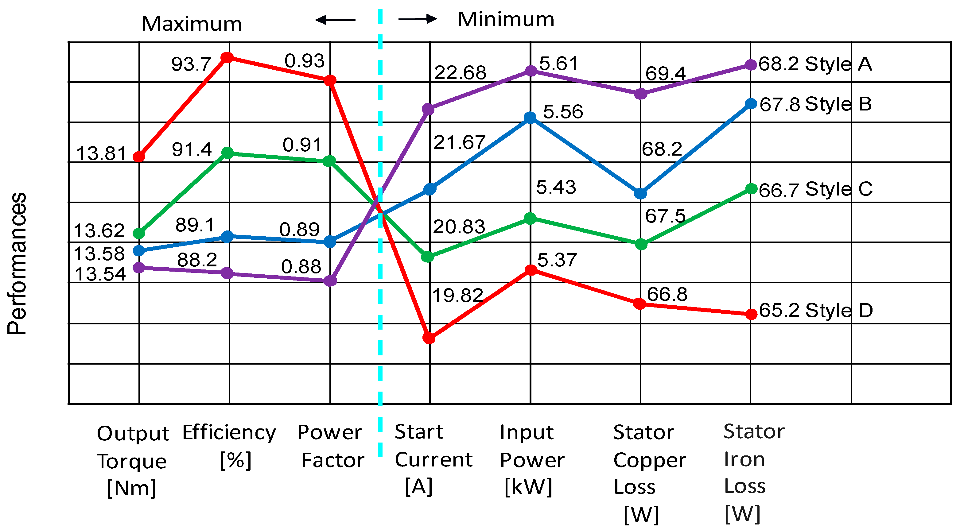
Table 6 lists some comparisons of the machine performance with MPCI and multi-high performance indices from Table 2, Table 3, Table 4 and Table 5 and Figure 5 to choose four kinds of styles with better performances as follows. Regarding the smallest summations in the minimization of stator iron loss, stator copper loss, starting current, and input power at the first-phase optimization according to Table 2 and Table 3, and Figure 3, the smallest summations sorted from small to large for the four kinds of styles are No. 8, 10, 3, and 15 in Table 2 and Table 3. Then, regarding the MPCI values in Figure 3 from Table 2 and Table 3, the smallest combination of design parameters in the stator part of the SCSCRIM design with the minimization combination as (A2B4C3D2E1), with regard to No. 8 in Table 2 and Table 3, can be found as Style D. Secondly, Style C is No. 10 in Table 2 and Table 3 from Figure 3. Thirdly, Style B is No. 3 in Table 2 and Table 3 from Figure 3. Fourth, Style A is No. 15 in Table 2 and Table 3 from Figure 3. Furthermore, regarding the largest summations in the maximization of the output torque, the output power, and the power factor at the second-phase optimization according to Table 4 and Table 5, and Figure 4, the largest summations sorted from large to small for the four kinds of styles are No. 8, 10, 3 and 15 in Table 2 and Table 3. Then, regarding the MPCI values in Figure 4 from Table 4 and Table 5, the largest combination of design parameters in the rotor part of the SCSCRIM design with the maximization combination as (a3b2c4d3e1), with regard to No. 10 in Table 4 and Table 5, can be found as Style D. Secondly, Style C is No. 8 in Table 4 and Table 5 from Figure 4. Thirdly, Style B is No. 3 in Table 4 and Table 5 from Figure 4. Fourth, Style A is No. 15 in Table 4 and Table 5 from Figure 4. Table 6 shows four kinds of SCSCRIM configurations with better performances as Styles D, C, B, and A from best, better, good, to general according to the above-mentioned skill. Comparing all performances for the four kinds of SCSCRIM configurations shown in Table 6, Style D of SCSCRIM is chosen as the best performance in the two-phase high-performance design with multi-objective optimization. Figure 5 shows the poly-line graph of several kinds of performances for stator iron loss, stator copper loss, starting current, input power, efficiency, power factor, and output torque in the four kinds of SCSCRIM configurations from Table 6.
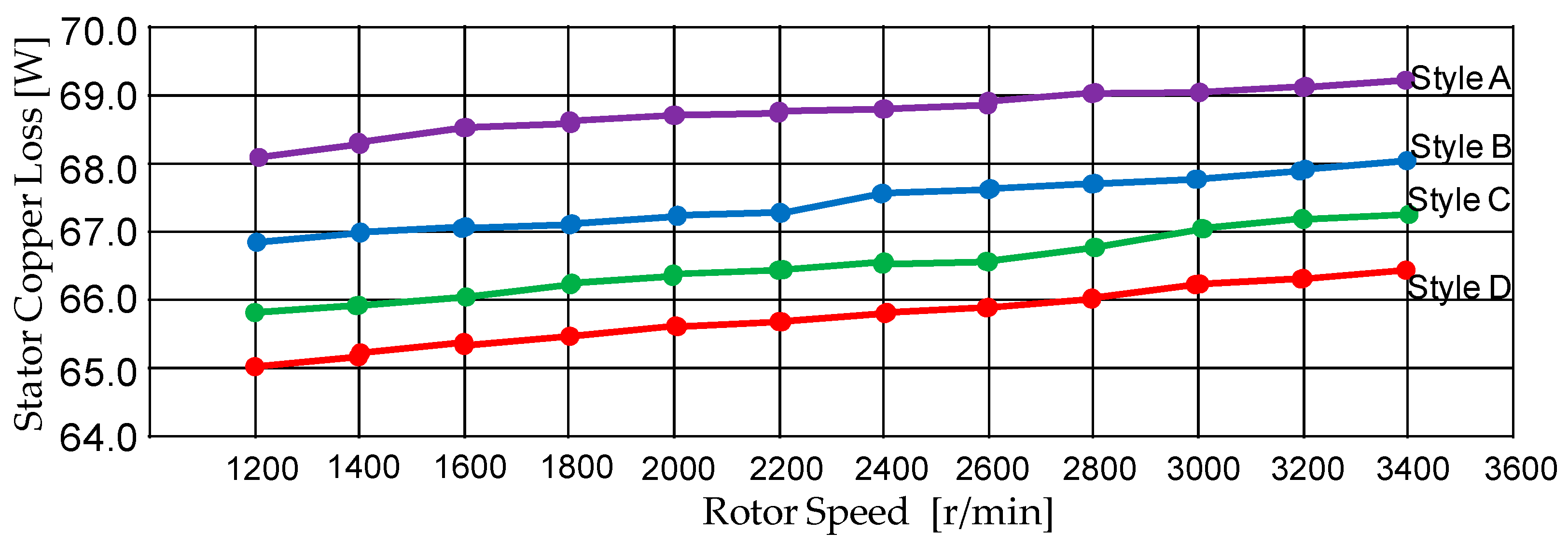
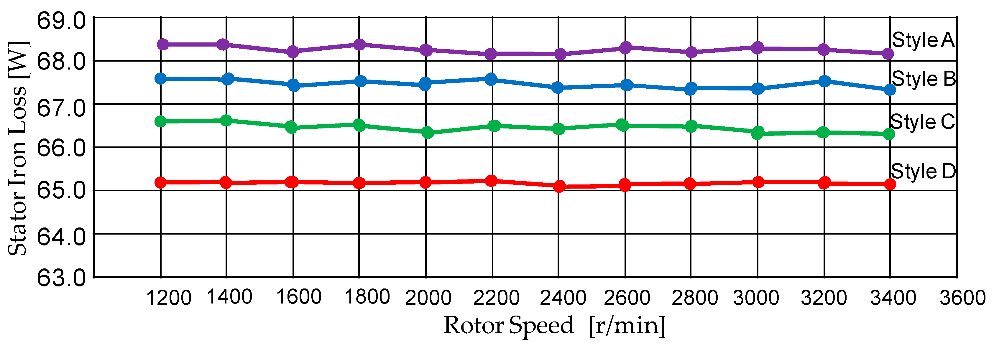
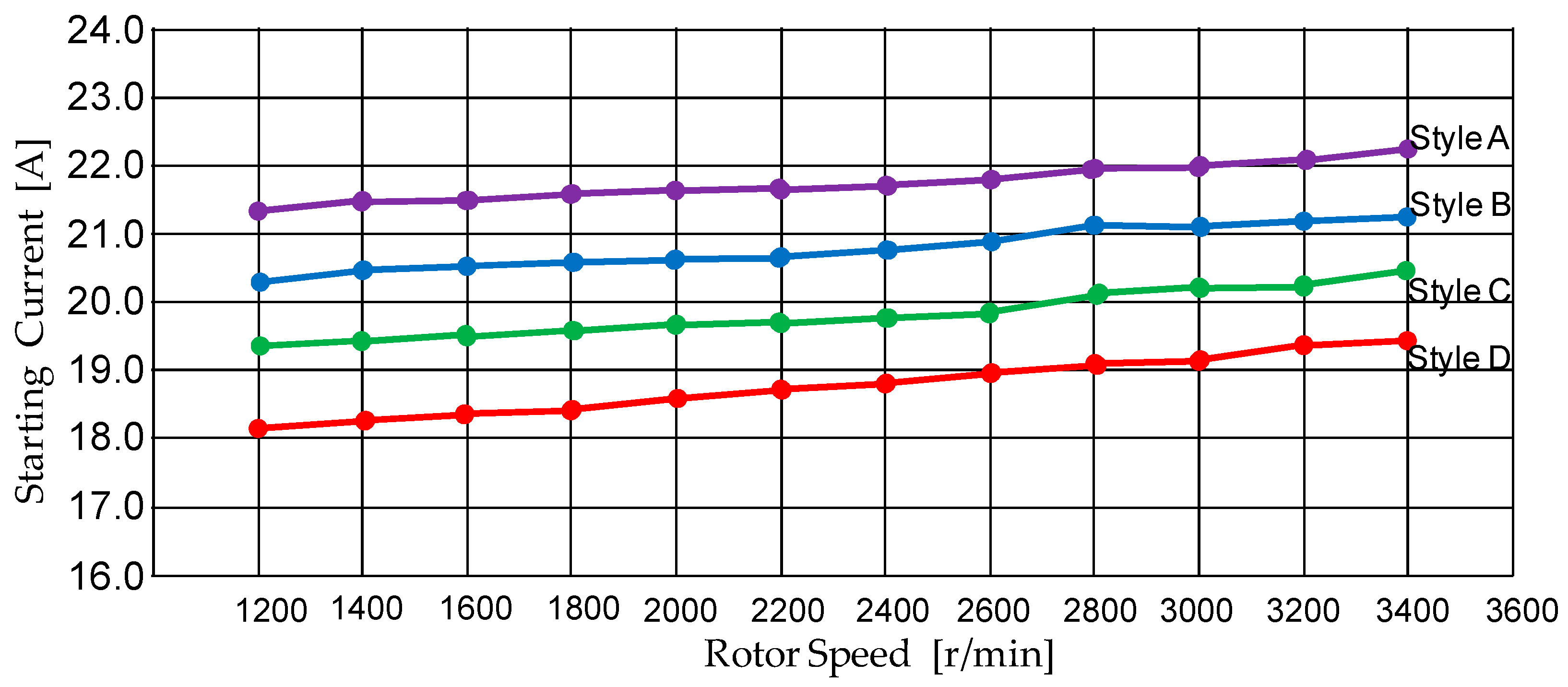
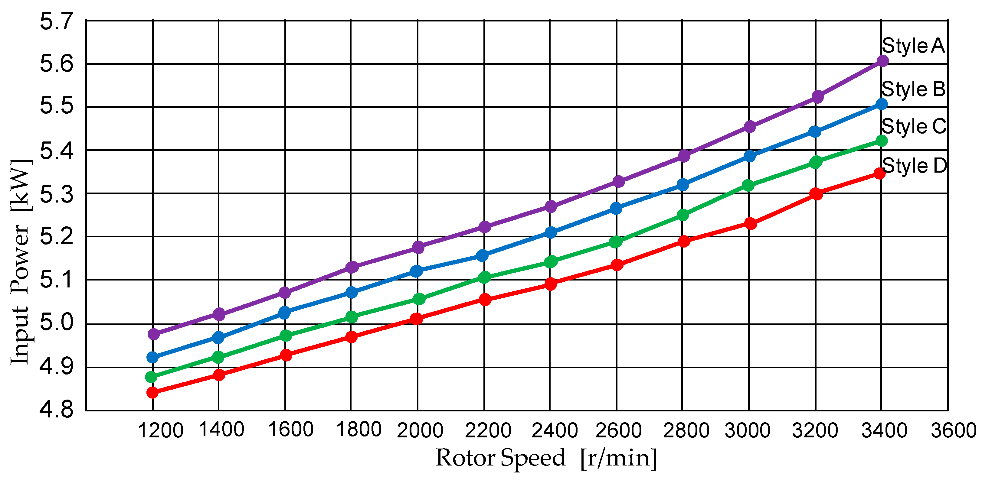
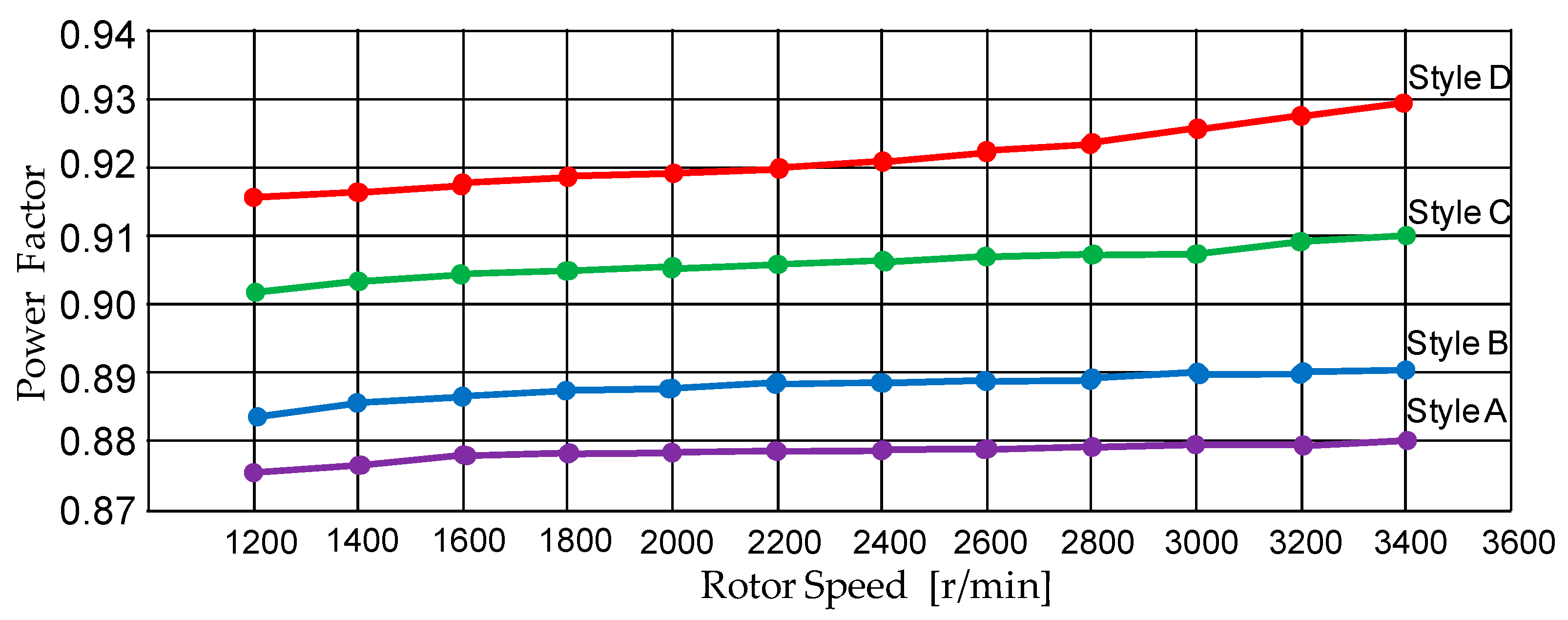
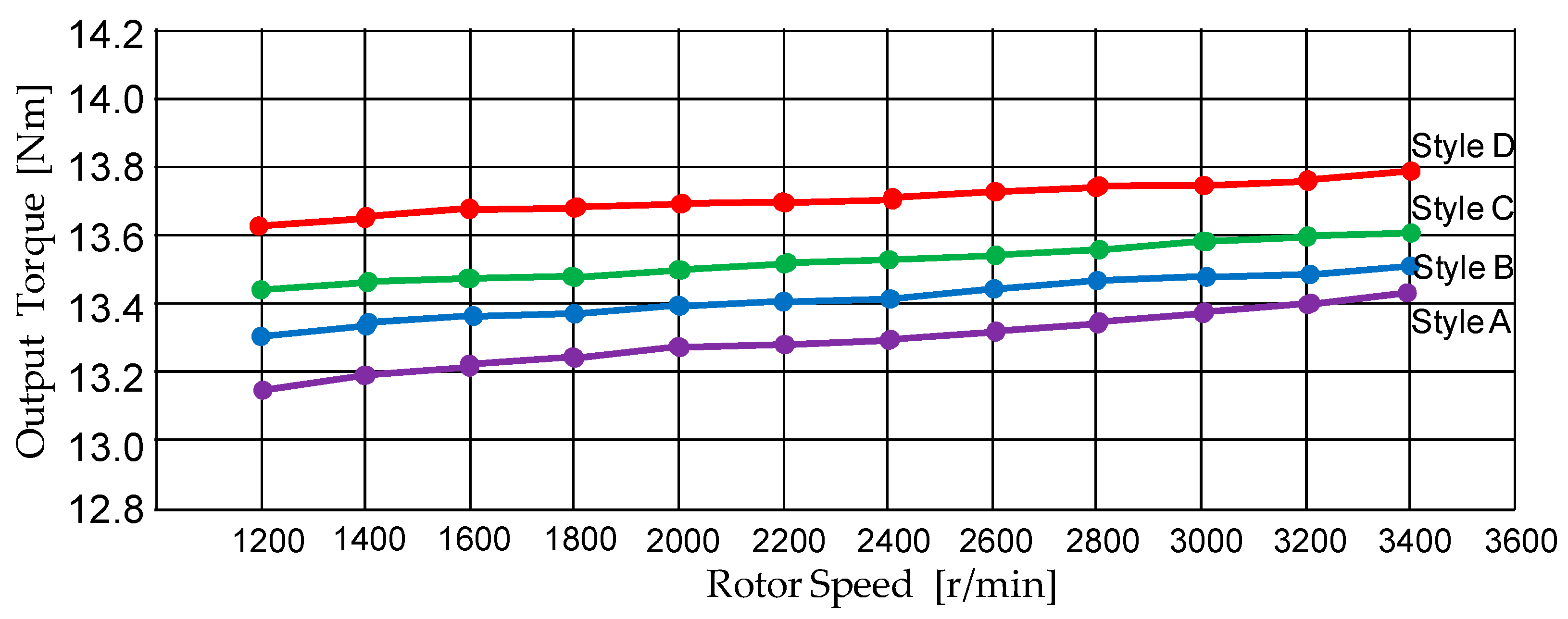
Furthermore, poly-line graphs from performance tests on stator copper loss, stator iron loss, starting current, input power, efficiency, power factor, and output torque for the four kinds of SCSCRIMs under several speeds via simulated results are shown in Figure 6, Figure 7, Figure 8, Figure 9, Figure 10, Figure 11 and Figure 12, respectively. In summary, it is seen that the two-phase high-performance design with multi-objective optimization can reduce stator copper loss, stator iron loss, starting current, and input power from the performance tests shown in Figure 6, Figure 7, Figure 8 and Figure 9, and it can raise efficiency, power factor, and output torque from the performance tests shown in Figure 10, Figure 11 and Figure 12 via simulated results. It is very obvious that many characteristic performances in Style D of SCSCRIM are superior to Styles A, B, and C through the high-performance design with multi-objective optimization by use of altered grey wolf optimization, the Taguchi method and FEA.

6. Results and Discussion

The comparative performances for four kinds of SCSCRIMs according to the two-phase high-performance program with multi-objective optimization with regards to seven configurations are listed in Table 6. Sticking-point observations for the seven kinds of performance configurations are given below.
  • The stator iron loss is cut down to 65.2 W in Style D.
  • The stator copper loss is cut down to 66.8 W in Style D.
  • The starting current is cut down to 19.82 A in Style D.
  • The input power is cut down to 5.37 kW in Style D.
  • The power factor is increased to 0.93 in Style D.
  • The efficiency is increased to 93.7% in Style D.
  • The output torque is increased to 13.81 Nm in Style D.
Style D for the SCSCRIM shown in Table 6 was chosen as the best performance in the two-phase high-performance design program with multi-objective optimization.
Furthermore, a comparative investigation of the optimization results with particle swarm optimization, bee colony optimization, ant colony optimization, and altered grey wolf optimization is shown in Table 7. The proposed altered grey wolf optimization with regards to seven configurations has faster computing time, faster searching speed of optimization, and better performances in comparison with particle swarm optimization, bee colony optimization, and ant colony optimization.
In summary, it is obvious that the two-phase high-performance design with multi-objective optimization by using altered grey wolf optimization, the Taguchi method and FEA can cut down the stator iron loss, the stator copper loss, the starting current, and the input power, and further enhances efficiency, power factor, and output torque. The proposed skill has more accurately calculated numbers, a more flexible combination of parameters, and faster optimized group selection than the Pareto optimization coupled with FEM in terms of calculated-time operation, optimized-term selection and better performance selection.
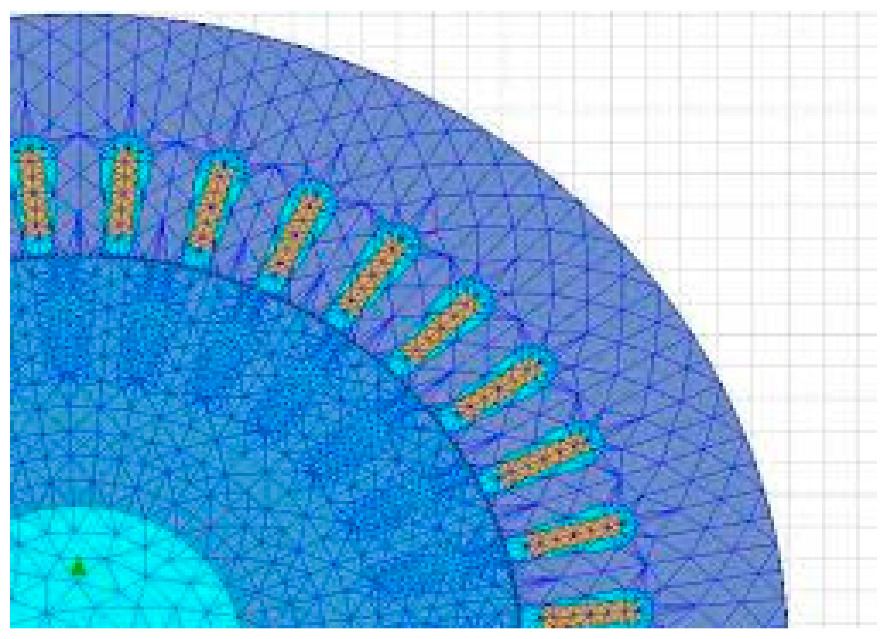
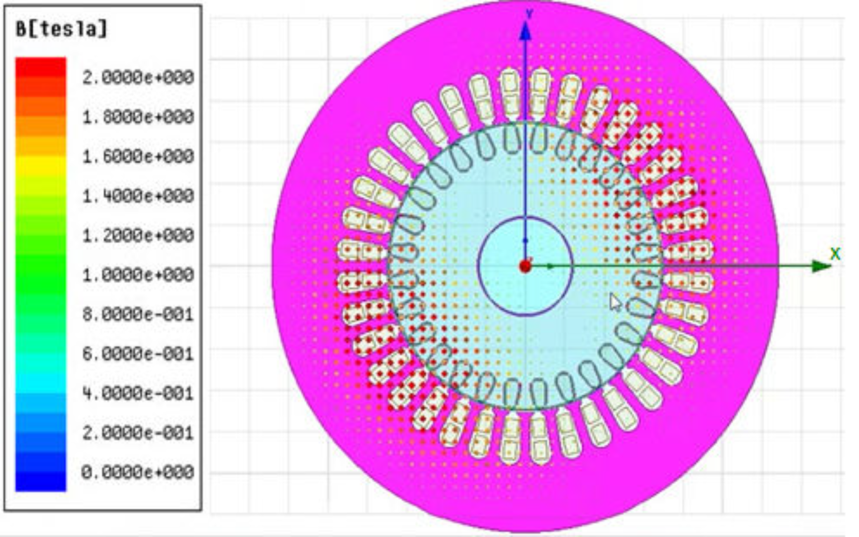
Finally, according to the proposed skill, Style D of SCSCRIM has completed the manufacturing body. Photo pictures of Style D of SCSCRIM are shown in Figure 13. The view of (a) the copper rotor; (b) the combination of stator, rotor and winding; and (c) the full cross of stator and six windings in Style D of SCSCRIM is shown in Figure 13a–c. A mesh plot of a SCSCRIM using the FEA method with quarter cross in Style D is shown in Figure 14. The flux density distribution of a SCSCRIM with full cross in Style D using the FEA method is shown in Figure 15.

7. Conclusions

In this paper, a multi-objective optimization design with high-performance property by using altered grey wolf optimization, the Taguchi method and the FEA method for tackling multi-objective optimization issues in a SCSCRIM is proposed to achieve faster optimized value selection and convergent speed. The multi-objective optimization design with high-performance property aims to achieve lower starting current, lower losses, lower input power, higher efficiency, higher output torque, and higher power factor. The proposed skill in the first-phase program is used for minimizing the starting current, stator iron loss, stator copper loss, and input power. The proposed skill in the second-phase program is used for maximizing the efficiency, output torque, and power factor. The best combination of design parameters in the stator part of the SCSCRIM design with the minimization combination as (A2B4C3D2E1), i.e., Style D from performance tests, is represented as follows: (1) the stator tooth width is 6.0 mm; (2) the stator slot height is 23.8 mm; (3) the stator boot width is 4.2 mm; (4) the stator slot opening width is 2.8 mm; and (5) the stator winding length per stator slot is 92 mm. The best combination of design parameters in the rotor part of the SCSCRIM design with the maximization combination as (a3b2c4d3e1), i.e., Style D from performance tests, is represented as follows: (1) the rotor tooth width is 4.5 mm; (2) the rotor slot height is 19.0 mm; (3) the rotor boot width is 4.0 mm; (4) the rotor slot opening width is 1.9 mm; and (5) the rotor winding length per rotor slot is 70 mm. The adopted high-performance SCSCRIM demonstrates 65.2 W in stator iron loss, 66.8 W in stator copper loss, 19.82 A in starting current, 5.37 kW in input power, 0.93 in power factor, 93.7% in efficiency, and 13.81 Nm in output torque.
The proposed skill has more accurately calculated numbers, a more flexible combination of parameters, and faster optimized group selection than the Pareto optimization coupled with FEM in terms of calculated-time operation, optimized-term selection and better performance selection. The proposed skill with higher performances has been evaluated and verified via a two-phase program design and some performance tests. The performance results of this study confirm the effectiveness of the proposed skill for obtaining high performance and optimal characteristics. The proposed skill has been successfully applied in solving high-performance issues of some electromagnetic facilities with multi-objective optimization.

Author Contributions

C.-H.L. conceived and designed the control system of experiments; C.-H.L. performed the software programs and the experiments; C.-H.L. analyzed the data; C.-H.L. wrote and revised the paper. All authors have read and agreed to the published version of the manuscript.

Funding

This research was funded by the Ministry of Science and Technology of Taiwan (Project MOST 108-2221-E-239-011-MY2).

Acknowledgments

The author would like to acknowledge the financial support of the Ministry of Science and Technology of Taiwan under grant MOST 108-2221-E-239-011-MY2.

Conflicts of Interest

The author declares no conflicts of interest.

References

  1. Nanoty, A.; Chudasama, A.R. Design and control of multiphase induction motor. In Proceedings of the IEEE International Electric Machines and Drives Conference, Niagara Falls, ON, Canada, 15–18 May 2011; pp. 354–358. [Google Scholar]
  2. Lin, C.H.; Hwang, C.C. Multiobjective optimization design for a six-phase copper rotor induction motor mounted with a scroll compressor. IEEE Trans. Magn. 2016, 52, 9401604. [Google Scholar] [CrossRef]
  3. Lin, C.H.; Hwang, C.C. Multi-objective optimization design using amended particle swarm optimization and Taguchi method for a six-phase copper rotor induction motor. Eng. Optim. 2017, 49, 693–708. [Google Scholar] [CrossRef]
  4. Zhao, H.; Zhang, J.; Wang, X.; Wang, Q.; Liu, X.; Luo, Y. A design method for cage induction motors with non-skewed rotor bars. IEEE Trans. Magn. 2014, 50, 769–772. [Google Scholar]
  5. Cunkas, M.; Akkaya, R. Design optimization of induction motor by genetic algorithm and comparison with existing motor. Math. Comput. Appl. 2006, 11, 193–203. [Google Scholar]
  6. Sun, Y.; Tang, J.; Shi, K. Design of a bearingless outer rotor induction motor. Energies 2017, 10, 705. [Google Scholar]
  7. Parasiliti, F.; Villani, M. Design of high efficiency induction motors with die-casting copper rotors. In Energy Efficiency in Motor Driven Systems; Springer: Berlin/Heidelberg, Germany, 2003; pp. 144–151. ISBN 3-540-00666-4. [Google Scholar]
  8. Daut, I.; Anayet, K.; Fauzi, A. Development of copper rotor of AC induction motor. Aust. J. Basic Appl. Sci. 2010, 4, 5941–5946. [Google Scholar]
  9. Kane, M. Design of copper rotor induction motor for mild-hybrid electric vehicle. In Proceedings of the IEEE International Transportation Electrification Conference, Chennai, India, 27–29 August 2015; pp. 1–6. [Google Scholar]
  10. Zhang, Q.; Liu, H.; Zhang, Z.; Song, T. A cast copper rotor induction motor for small commercial EV traction: Electromagnetic design, analysis, and template tests. CES Trans. Electr. Mach. Syst. 2018, 2, 417–424. [Google Scholar] [CrossRef]
  11. Mittelstedt, M.; Hansen, C.; Mertiny, P. Design and multi-objective optimization of fiber-reinforced polymer composite flywheel rotors. Appl. Sci. 2018, 8, 1256. [Google Scholar] [CrossRef] [Green Version]
  12. Anwar, N.; Deng, H. A hybrid metaheuristic for multi-objective scientific workflow scheduling in a cloud environment. Appl. Sci. 2018, 8, 538. [Google Scholar] [CrossRef] [Green Version]
  13. Shen, Y.; Wang, X.; Chen, J. Wind power forecasting using multi-objective evolutionary algorithms for wavelet neural network-optimized prediction intervals. Appl. Sci. 2018, 8, 185. [Google Scholar] [CrossRef] [Green Version]
  14. Mathur, V.K. How well do we know Pareto optimality. J. Econ. Educ. 1991, 22, 172–178. [Google Scholar] [CrossRef]
  15. Kanbur, R. Pareto’s revenge. J. Soc. Econ. Dev. 2005, 7, 1–11. [Google Scholar]
  16. Barr, N. The Relevance of Efficiency to Different Theories of Society, Economics of the Welfare State, 5th ed.; Oxford University Press: Oxford, UK, 2012; pp. 46–51. ISBN 978-0-19-929781-8. [Google Scholar]
  17. Yamazaki, K.; Suzuki, A.; Ohto, M.; Takakura, T.; Nakagawa, S. Equivalent circuit modeling of induction motors considering stray load loss and harmonic torques using finite element method. IEEE TRANS. MAGN. 2011, 47, 986–989. [Google Scholar] [CrossRef]
  18. Ahn, J.; Lee, D.; Park, G.J.; Kim, Y.J.; Kim, J.; Jung, S.Y. Numerical design compatibility of induction motor with respect to voltage and current sources. IEEE TRANS. MAGN. 2014, 50, 773–776. [Google Scholar] [CrossRef]
  19. Emary, E.; Yamany, W.; Hassanien, A.E.; Snasel, V. Multi-objective gray-wolf optimization for attribute reduction. Procedia Comput. Sci. 2015, 65, 623–632. [Google Scholar] [CrossRef] [Green Version]
  20. Mosavi, M.; Khishe, M.; Ghamgosar, A. Classification of sonar data set using neural network trained by gray wolf optimization. Neural Netw. World 2016, 26, 393–415. [Google Scholar] [CrossRef] [Green Version]
  21. Parsian, A.; Ramezani, M.; Ghadimi, N. A hybrid neural network-gray wolf optimization algorithm for melanoma detection. Biomed. Res. 2017, 28, 3408–3411. [Google Scholar]
  22. Sanchez, D.; Melin, P.; Castillo, O. A grey wolf optimizer for modular granular neural networks for human recognition. Comput. Intell. Neurosci. 2017, 8, 1–26. [Google Scholar] [CrossRef] [Green Version]
  23. Khandelwal, A.; Bhargava, A.; Sharma, A.; Sharma, H. Modified grey wolf optimization algorithm for transmission network expansion planning problem. Arab. J. Sci. Eng. 2018, 43, 2899–2908. [Google Scholar] [CrossRef]
  24. Hwang, C.C.; Chang, C.M.; Liu, C.T. A fuzzy-based Taguchi method for multiobjective design of PM motors. IEEE TRANS. MAGN. 2013, 49, 2153–2156. [Google Scholar] [CrossRef]
  25. Lin, C.H.; Hwang, C.C. High performances design of a six-phase synchronous reluctance motor using multi-objective optimization with altered bee colony optimization and Taguchi method. Energies 2018, 11, 2716. [Google Scholar] [CrossRef] [Green Version]
  26. Kahhal, P.; Brooghani, S.Y.A.; Azodi, H.D. Multi-objective optimization of sheet metal forming die using FEA coupled with RSM. J. Mech. Sci. Technol. 2013, 27, 3835–3842. [Google Scholar] [CrossRef]
  27. Moghaddami, M.; Anzalchi, A.; Moghsdasi, A.; Sarwat, A. Pareto optimization of circular power pads for contactless electric vehicle battery charger. In Proceedings of the IEEE Industry Applications Society Annual Meeting, Portland, OR, USA, 2–6 October 2016; pp. 1–6. [Google Scholar]
  28. Faiz, J.; Sharifian, M.B.B. Optimal design of three phase induction motors and their comparison with a typical industrial motor. Comput. Electr. Eng. 2001, 27, 133–144. [Google Scholar] [CrossRef]
  29. Faiz, J.; Sharifian, M.B.B.; Keyhani, A.; Proca, A. Performance comparison of optimally designed induction motors with aluminum and copper squirrel-cages. Electr. Mach. Power Syst. 2000, 28, 1195–1207. [Google Scholar]
  30. Fei, R.; Fuchs, E.F.; Huang, H. Comparison of two optimization techniques as applied to three-phase induction motor design. IEEE Trans. Energy Convers. 1989, 4, 651–660. [Google Scholar] [CrossRef]
  31. Lin, C.H. Backstepping control and revamped recurrent fuzzy neural network with mended ant colony optimization applied in SCRIM drive system. J. Intell. Fuzzy Syst. 2019, 36, 3447–3459. [Google Scholar] [CrossRef]
Figure 1. Structure of the six-phase copper squirrel cage rotor induction motor (SCSCRIM).
Energies 13 02282 g001
Figure 2. Flow chart of the optimization procedure with two-phase multi-objective optimization for SCSCRIM design.
Energies 13 02282 g002
Figure 3. The MPCI values for each element with corresponding levels in the first-phase design.
Energies 13 02282 g003
Figure 4. The MPCI values for each element with corresponding levels in the second-phase design.
Energies 13 02282 g004
Figure 5. Comparison of several kinds of performances for four kinds of SCSCRIMs.
Energies 13 02282 g005
Figure 6. Poly-line graph of stator copper loss for four kinds of SCSCRIMs under several speeds.
Energies 13 02282 g006
Figure 7. Poly-line line graph comparing stator iron loss for four kinds of SCSCRIMs under several speeds.
Energies 13 02282 g007
Figure 8. Poly-line graph of starting current for four kinds of SCSCRIMs under several speeds.
Energies 13 02282 g008
Figure 9. Poly-line graph of input power for four kinds of SCSCRIMs under several speeds.
Energies 13 02282 g009
Figure 10. Poly-line graph of efficiency for four kinds of SCSCRIMs under several speeds.
Energies 13 02282 g010
Figure 11. Poly-line graph of power factor for four kinds of SCSCRIMs under several speeds.
Energies 13 02282 g011
Figure 12. Poly-line graph of output torque for four kinds of SCSCRIMs under several speeds.
Energies 13 02282 g012
Figure 13. Photo pictures of a SCSCRIM in Style D: (a) copper squirrel cage rotor; (b) combination of stator, rotor and six windings; (c) full cross of stator and six windings.
Energies 13 02282 g013
Figure 14. Mesh plot of a SCSCRIM using the finite element analysis (FEA) method with quarter cross in Style D.
Energies 13 02282 g014
Figure 15. Flux density distribution of a SCSCRIM with full cross in Style D using the FEA method.
Energies 13 02282 g015
Table 1. Formatted parameters of the SCSCRIM.
ParameterValue
Stator outer diameter [mm]128.5
Stator inner diameter [mm]65.5
Rotor outer diameter [mm]65.0
Rotor inner diameter [mm]28.0
Air gap length [mm]0.5
Stack length [mm]76
Number of poles2
Stator slot number36
Rotor slot number32
Rated output power [kW] 5
Rated speed [r/min]3476
Rated current [A]10.6
Iron materialASTM 532
Table 2. Orthogonal array L16 matrix by the Taguchi method and performance tests.
No.Control ElementsStator Iron LossStator Copper LossStarting CurrentInput Power
EDCBA[W][W][A][kW]
11111168.870.923.455.94
22222169.170.624.945.86
33333167.868.221.675.56
44444168.669.123.525.79
54321270.271.122.865.72
63412269.567.123.565.75
72143269.669.822.935.87
81234265.266.819.825.37
92431369.970.123.015.86
101342366.767.520.835.43
114113368.970.223.825.92
123224370.169.923.135.87
133241470.467.423.135.76
144132469.169.723.365.86
151423468.269.422.685.61
162314469.469.926.515.86
Table 3. Conversion array of signal-to-noise (S/N) ratio, altered grey wolf optimization modulus and multiple performance characteristics index (MPCI).
No.S/N RatioAltered Grey Wolf Optimization ModulusMPCIFEA
Stator Iron LossStator Copper Loss Starting CurrentInput PowerStator Iron LossStator Copper LossStarting CurrentInput Power
11.41.61.42.80.970.360.680.810.68441.04
21.11.91.12.90.810.260.690.820.65418.15
30.81.40.92.40.560.260.650.680.60364.57
41.61.51.62.70.630.380.670.900.64404.76
51.31.81.72.60.730.260.690.740.63393.94
61.11.61.12.70.680.310.730.860.61383.12
70.91.60.92.70.690.280.660.760.62397.45
80.61.10.72.20.480.240.580.610.56328.61
90.81.41.82.90.570.280.690.810.64409.64
100.71.20.72.30.500.250.610.620.58344.24
111.11.51.12.50.600.340.850.710.68439.57
121.01.71.02.60.810.290.790.680.62397.51
130.91.80.92.80.510.280.680.740.61383.82
141.11.61.12.70.700.270.740.860.66422.38
150.71.40.82.50.550.260.640.680.61374.06
161.11.81.12.90.690.330.850.760.65418.24
Table 4. Orthogonal array L16 matrix by the Taguchi method and performance tests.
No.Control ElementsOutput Torque Efficiency Power Factor
edcba[Nm][%]
11111112.8587.70.86
22222113.1587.40.84
33333113.5889.00.89
44444113.0387.90.85
54321213.2088.00.81
63412213.0087.40.84
72143213.3187.10.86
81234213.6191.40.91
92431313.4487.40.81
101342313.8193.70.93
114113313.1287.60.87
123224312.7086.90.83
133241412.4088.10.87
144132413.1287.30.85
151423413.5488.20.88
162314413.3686.50.82
Table 5. Conversion array of S/N ratio, altered grey wolf optimization modulus and MPCI.
No.S/N RatioAltered Grey Wolf Optimization ModulusMPCIFEA
EfficiencyPower FactorOutput TorqueEfficiencyPower FactorOutput Torque
1−2.40−1.86−2.890.770.670.710.666.55
2−2.17−1.99−2.930.810.660.730.676.64
3−1.85−1.48−2.590.830.680.760.686.88
4−1.92−1.89−2.980.730.600.660.646.37
5−2.20−1.84−2.800.730.660.640.676.68
6−2.10−1.76−2.720.680.620.700.626.14
7−1.96−1.85−2.750.790.640.680.585.74
8−1.84−1.38−2.510.860.740.780.697.14
9−1.93−1.59−2.900.710.630.640.646.36
10−1.82−1.30−2.480.880.760.790.707.42
11−2.01−1.50−2.880.700.640.670.565.56
12−2.00−1.63−2.920.760.610.660.605.89
13−1.92−1.59−2.670.760.680.680.626.14
14−2.16−1.63−2.770.700.670.730.616.04
15−1.87−1.42−2.540.840.700.760.676.72
16−1.89−1.56−2.830.790.680.760.636.20
Table 6. Comparative performances for four kinds of SCSCRIM configuration design.
ConfigurationsStyle AStyle BStyle CStyle D
Stator iron loss [W]68.267.866.765.2
Stator copper loss [W]69.468.267.566.8
Starting current [A]22.6821.6720.8319.82
Input power [kW]5.615.565.435.37
Efficiency [%]88.289.191.493.7
Power factor [-]0.880.890.910.93
Output torque [Nm]13.5413.5813.6213.81
Table 7. Comparative investigation of the optimization results by four kinds of competitive algorithms for Style D of SCSCRIM design.
ConfigurationsParticle Swarm Optimization [3]Bee Colony Optimization [25]Ant Colony Optimization [31]Proposed Altered Grey Wolf Optimization
Stator iron loss [W]65.665.865.765.2
Stator copper loss [W]67.167.567.866.8
Starting current [A]19.9520.1720.2319.82
Input power [kW]5.435.475.495.37
Efficiency [%]93.293.092.893.7
Power factor [-]0.920.910.910.93
Output torque [Nm]13.7413.6513.5613.81
Computing time [s]16.5217.3517.8615.58
Time spent searching for optimized value [s]18.6819.4619.8117.36