Abstract
This paper presents an inductive power transfer system on the basis of a double single-phase three-level T-type inverter and two split transmitting coils for constant current and constant voltage wireless charging of low-voltage light electric vehicle batteries with closed-loop control, considering time-delay communication constraints. An optimal control structure and a modified control strategy were chosen and implemented to the wireless power transfer system as a result of a review and analysis of existing solutions. The control system analysis and adjustment of the coefficients of the regulator using Laplace transform were performed. Our study addressed the behavior of the control system with different time delays as well as the dynamic response of the system. The detecting algorithm of a secondary coil was proposed, which ensured efficient system operation and increased the functionality, safety and usability of the device. The efficiency of energy transfer of 90% was reached at the transmitted power of 110 W, which is at the level of existing solutions considered in the article and opens the way to the commercialization of the proposed solution. Therefore, the feasibility of using a nonclassical multilevel inverter, together with split transmitting coils for wireless charging was confirmed.
1. Introduction
Control systems based on various strategies are an integral part of the wireless power transfer (WPT) system for efficient energy transfer and overall circuit operation. WPT systems for the static or dynamic charging of electric vehicles, low-power applications, such as mobile devices, electric bikes, always need regulation and control, including adjustment of the output current and voltage for the optimal charging of batteries.
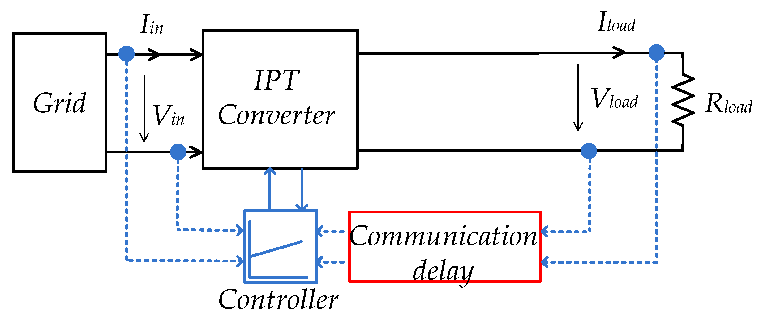
Output power and the efficiency of WPT depend strongly on a coupling coefficient and load condition in an open-loop system [1]. Closed-loop control systems allow the monitoring of both the input and output parameters of the whole inductive power transfer (IPT) system (Figure 1). Simultaneously, the overall performance of the control system strongly depends on the time delay of feedback information exchange. Delays in the transmission of information over the wireless network are a topical issue [2] and can lead to disruptions of the WPT control process.
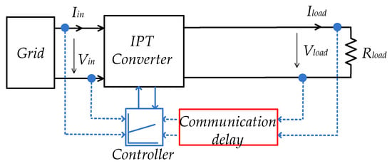
Figure 1.
The overall structure of a closed-loop control system for IPT.
The aim of the article is to provide proper closed-loop control with the communication delay model of a wireless power transmission system based on a dual T-type inverter combined with two transmitter inductors in the closed-loop mode for charging low-voltage batteries. This article presents a study and justification into the range of delay in which the normal operation of the wireless charging system is possible. For this purpose, the communication delay is taken into account when analyzing the transfer function of the WPT system with a closed-loop control system. The advantage of this approach is that there is no need for additional schemes of technical solutions and complex software development. Two fundamental control modes, constant current (CC) and constant voltage (CV), should be implemented to reduce the exploitation wear of the batteries and extend their service life.
This article consists of five sections. Section 2 is devoted to the description of the entire wireless charging system. Then Section 3 analyzes the main structures and control strategies and selects the most suitable ones, while Section 4 describes in detail the proposed control system considering time-delay communication constraints. Finally, in Section 5, the results of the experimental verification of the proposed system for wireless charging of batteries are presented.
2. Description of Evaluated Inductive Power Transfer System
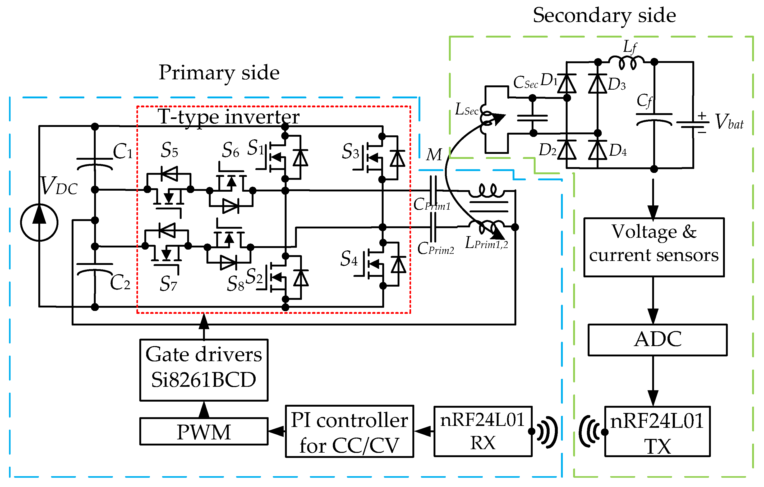
The T-type topology of a high-frequency inverter with split transmitting coils and with PI-controller is firstly proposed to achieve CC/CV charging modes in the low-power wireless charger (Figure 2). The advantages of such a WPT system have been described in [1] and the effectiveness of such an approach in an open system has been proven. In particular, the use of T-type has some advantages in relation to other multilevel inverters: smaller size, simpler operation principles, lower conduction losses and a smaller number of semiconductors [1]. The most important advantage of the T-type solution in the WPT application is that only half of the dc-link voltage is applied to the primary side coil, which reduces inductance and the size of the primary coil [1]. Therefore, this topology together with the split primary coils and the use of series−parallel (SP) compensation also reduces the inductance and size of the secondary coil [1].
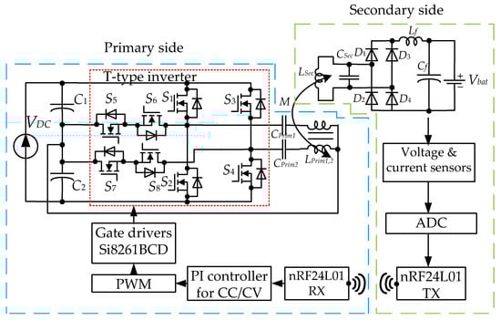
Figure 2.
Proposed topology of the T-type based IPT close-loop system for battery charging.
Different types of switches can be used in the T-type neutral point clamped (NPC) inverters. The conventional silicon insulated gate bipolar transistors (Si-IGBTs) are gradually coming out of use in industrial circuits of multilevel inverters because of their drawbacks. IGBTs have the disadvantage of slower switching capability due to their bipolar output characteristic [3]. The reverse blocking voltage capability of the conventional IGBT is very low, there are relatively large power losses, (as well as the usual field-effect transistors [4]), because of IGBTs’ non-ideal internal structure [5].
The silicon carbide metal-oxide-semiconductor field-effect transistor (SiC MOSFET) and the gallium nitride high-electron-mobility transistor (GaN HEMT) have proven themselves well in power electronic devices. In [6], the performance of a single-phase T-type NPC inverter is compared, using three types of 600 V switches (Si IGBT, SiC MOSFET, GaN HEMT). As reported in [6], SiC MOSFETs had the lowest gate loss for switching frequencies above 100 kHz; relative to Si IGBTs, the volume of the output filter could be reduced by 43%, gate driver loss, power loss, and switching losses were lower [3]. The efficiency was more than 97.5% at the power of 500–2500 W, and the heat sink volume was lower.
SiC-based devices operate very effectively in the high-voltage range applications, especially above about 600 V, and are currently considered the most suitable devices for efficient power conversion [7]. SiC has superior thermal conductivity, several times higher in relation to other types, while GaN has the highest bandgap and electron mobility [7]. However, GaN has very high sensitivity to overvoltages. In this case, SiC with 1.2 kV braking voltage will have greater reliability. In addition, the conduction losses are almost the same with the GaN transistors [8,9].
Finally, the proposed circuit of a closed-loop system with a multilevel converter for the wireless charging of a low-voltage battery is presented in Figure 2. The 3-level SiC-based T-type converter consists of a full-bridge 2-level inverter (S1–S4) connected to the anti-series branch of the semiconductor switches (bidirectional auxiliary switches S5–S8) [1]. The input voltage divided by two input capacitors C1, C2 enters the T-type inverter where it is converted into alternating current, which is transmitted to the secondary side of the transformer.
The primary coils Lprim1 and Lprim2 with an air gap, the energy is transmitted to the secondary side through the secondary coil Lsec. The resulting secondary current is rectified by the passive full-bridge rectifier D1–D4, shaped by LC filter (Cf, Lf) and delivered to the loaded battery (Vbat).
The use of two primary split inductors reduces the current flowing through the switches and each of the transmission coils, thus reducing static losses and increasing system efficiency [1]. Moreover, the use of two split inductors on one ferrite core reduces the volume of ferrite by half compared to the two conventional transmission coils.
The use of an SP compensation link comprising of Cprim1, Cprim2—primary compensating capacitances and Csec—secondary compensating capacitance, at a given power level is fully justified, the advantages and disadvantages are described in [10]. Systems with SP compensation work efficiently with a wide range of loads in addition to the advantages of middle-power and low-power application and allow the reduction of the dimensions of a receiver coil [10,11].
The closed-loop control employs a PI controller with the PWM modulation strategy to provide CC and CV output modes by using current and voltage feedbacks from the secondary side. The feedback data transmission is achieved by using a radio frequency transmitter (module nRF24L01) on 2.4 GHz. The detailed description of the chosen solution is discussed in the next section.
3. Control Systems for Constant Current and Constant Voltage Modes
It is necessary to implement different control systems to achieve CC/CV modes. The “control structure” is defined as a type of a system topology indicating which component of the system will be the subject of regulation and where it is located. The “control strategy” or “control method” is an algorithm that provides the regulation of the system component. The choice of control method depends on the choice of control structure.
3.1. Selection of Control Structure for Implementation of CC/CV Modes
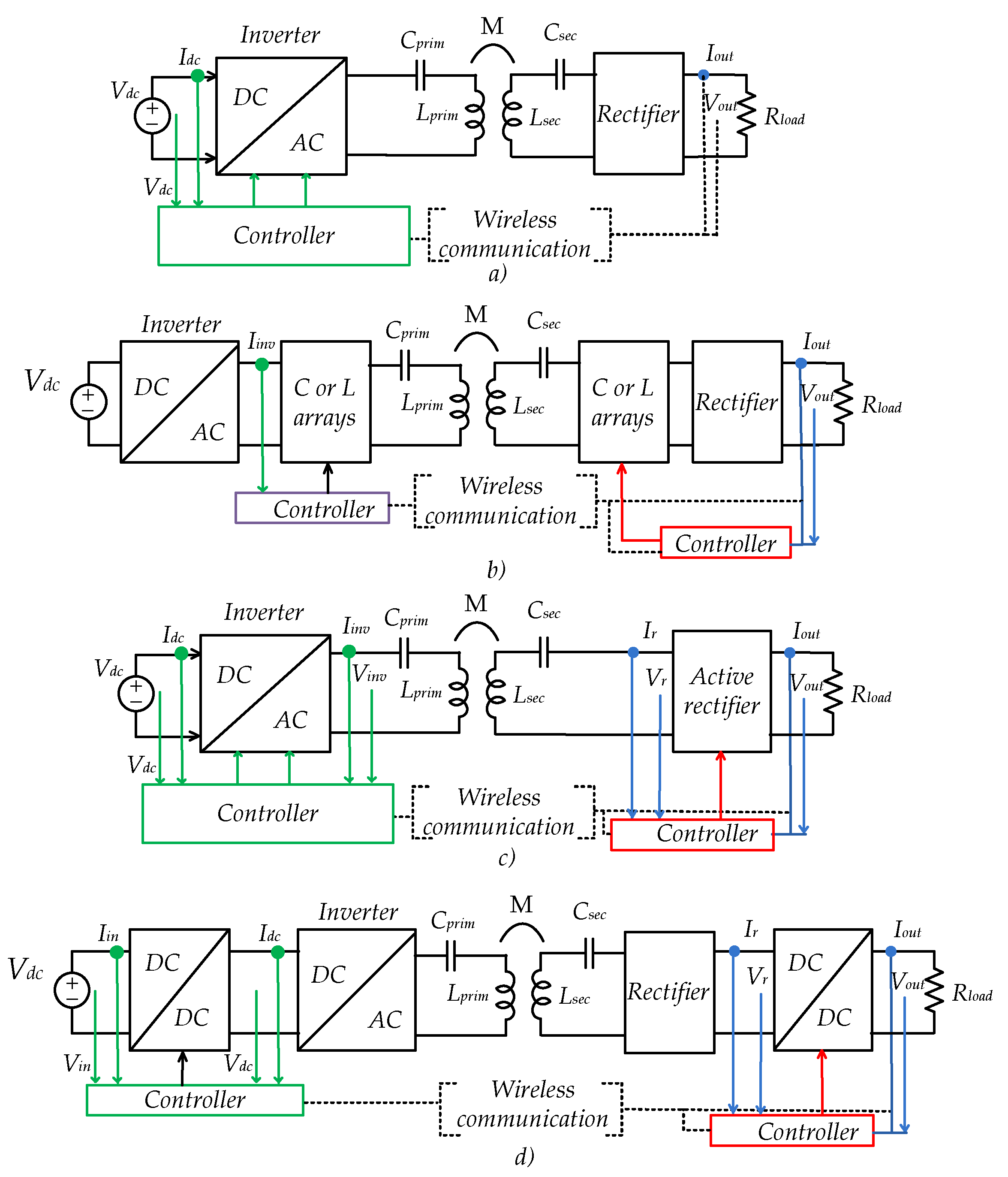
Papers [12,13] indicate that the closed-loop control strategy is essential to ensure accurate and stable charging. As shown in Figure 3, the basic structures widely used for the regulation of the charging current and voltage are divided into four groups: primary-side inverter control (Figure 3a), impedance matching (IM) (Figure 3b), dual-side active bridge control [14,15] (Figure 3c), and DC level control (Figure 3d) [12]. Arrows indicate the monitoring parameters used; different sets of parameters may be needed for each specific case of the strategy of control. A summary and comparison of the considered control structures with the indication of their main advantages and disadvantages are presented in Table 1.
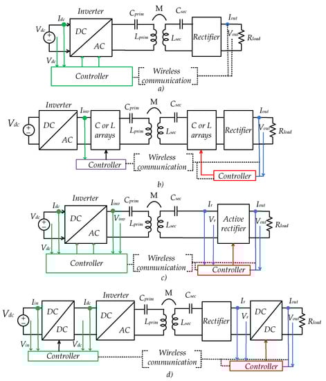
Figure 3.
Circuit diagrams of main control structures considered for WPT: (a) inverter control; (b) impedance matching; (c) dual active bridge control (adapted from ref. [12]); (d) dual dc-dc control (adapted from ref. [12]).

Table 1.
Comparison of evaluated control structures.
The structure in Figure 3a is the most frequently used for phase shift or frequency control, especially when CC or CV output mode is required. A possible functionality is to control the maximum efficiency of energy transfer, which is the most common structure in the paper under consideration. This structure is also the simplest, reducing cost, size, complexity and loss compared to the conventional IPT dual-side controller [16].
The IM structure (Figure 3b) is commonly applied for high frequency and low power applications [12]. In this scheme, IM control is achieved by switching set of capacitors and inductors by using relays or semiconductor switches (Figure 3b). The value of the capacitors and inductors changes significantly the output voltage. With a mismatch of the impedance between the power converter and the load, the output voltage may decrease [13]. Due to the bulky and complicated capacitor and inductor matrix, the system size and control complexity increase significantly with power capacity [17]. In addition, the resolution of IM is limited by the discrete capacitor and inductor values.
In Figure 3d a combined variant [13,18,19] with additional dc-dc converters on both sides is presented. It proposes an efficiency evaluation strategy for the closed-loop control schemes. The control scheme based on the dual dc-dc structure is unique and prominent in that it fixes the operating frequency at the receiving-side resonant frequency and converts both the input voltage and the load resistance at the same time. Thus, the point of maximum efficiency on the constant voltage trajectory can be tracked dynamically. Therefore, the output voltage of the system can be constantly monitored and its efficiency can be optimized [18].
The DC-DC converter in the receiving side is a reasonable solution to regulate the output voltage. According to the input voltage, the output voltage can be maintained by varying the conversion ratio. The fixed operating frequency of the closely coupled system does not require a frequency tracking scheme [13]. As compared to the preregulation, the voltage gain from the inverter’s input to the rectifier’s output is related to the load conversion ratio, because the equivalent load resistance is converted by the dc-dc converter in the receiving side [18]. The secondary-side dc-dc converter allows the feedback link to be avoided.
Studies on WPT systems (Figure 3c) with dual active bridges have attracted great attention due to their low conduction losses, power regulation, load transformation and reactance compensation [20]. This structure of control allows for independent control on the primary and secondary sides. In most cases, the feedback link between the parties is not required. The evident drawbacks of the strategies in this structure are the increased complexity of control and the increase in the number of semiconductor elements. A dual active bridge structure provides a practical method to overcome the main drawback of most single-side controlled inductive power transfer systems, which is a significant efficiency drop outside the nominal operating point [21].
It is possible to control only the active rectifier (Figure 3c) [22]. Therefore there will be no need for wireless data transmission, system reliability and data transfer speed will increase. As there will be additional power losses on switches and drivers of the secondary side, control will become more difficult, quantity and cost of system components will increase. If the WPT is operated in the CV charging mode, the efficiency of both control strategies is almost the same [23]. It is perfectly suited for a PI-controller to implement and maintain these modes.
However, in the evaluated case, the simplified system is required. It is impractical to add an additional dc-dc converter on the secondary side for a 100 W power system. At low power, this will reduce reliability and cost, increase losses, weight and dimensions of the system.
Therefore, the concept of Figure 3a was taken as a basis for implementation, which in this case, was very expedient. It is one of the simplest and most effective solutions [23,24,25]. In this case, the control of the output voltage and current of charging batteries was realized by the primary side inverter. On the secondary side, there will be only voltage and current sensors, an analogue-to-digital converter (ADC) and the transmitter of these data. This control structure is used for the implementation of CC and CV modes in the majority of applications [23,26,27].
3.2. Selection of Control Strategy for Implementation of CC/CV Modes
In most of the articles considered, the developed and known control strategies are used to achieve maximum efficiency of the scheme and power transfer. To achieve maximum efficiency, different strategies of control, phase shift or phase angle are controlled via pulse-width modulation (PWM). For CC/CV, a simple duty cycle is mainly used.
Control strategies may also vary depending on the system structure. Well-known phase control and frequency control methods for a voltage source inverter (VSI) on the primary side are most widely used. Control strategies include a variation of either the phase shift between the two converter bridge legs, the switching frequency or the dc-link voltage [28].
For T-type inverters, different strategies, modifications and combinations can also be used. The study presented in [29] proposes a power decoupling control method based on a discontinuous current mode for a T-type neutral point clamped (NPC) inverter. The study in [30] presents an improved hysteresis current control method for a 5-level T-type inverter. The proposed modulation technique achieves the desired value of output current and ensures high-efficiency conversion ratio at the output. The model of the system is used to establish the equations that can be applied to predict values of the load voltage and the dc-link capacitor voltages at the next sampling period [31]. All these strategies are too complex, expensive and unreasonable for low power application.
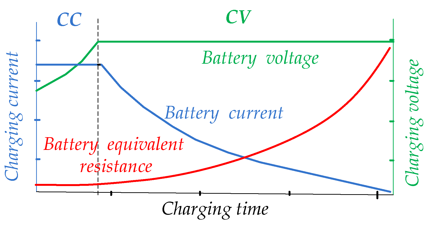
As our aim was to investigate the development of wireless charging, it is mandatory to control the output voltage and current. For a qualitative and safe process of charging a battery and extending its operation, two operating modes should be implemented (Figure 4), [32,33].
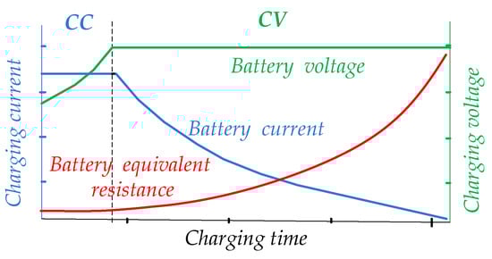
Figure 4.
Typical charging profile of the battery (adapted from ref. [27,32]).
So, at the first stage, the battery will be charged with a fixed current that is proportional to the capacity of the battery (CC mode). This current will be held constant until the charging-end voltage is reached [34]. When a battery is deeply discharged, the maximum current in the CC mode has to be applied. When the battery voltage reaches the operating voltage, then the transition to the CV mode should be performed [27]. At the same time, the current decreasing to a minimum value will be considered as the completion of the charging process. Approximately up to 80% of the battery is charged in the CC mode and then in the CV. The required time for charging in the CC mode is relatively shorter than in the CV mode [26,27].
There are known methods for accurate but relatively complex battery power capacity estimation [35] and state of charge estimation [36,37]. A rough estimation of battery capacity is possible on a curve on a typical charging profile (which is usually provided by manufacturers), knowing the equivalent resistance of the battery.
ADC is used to convert data from the current and voltage sensors at the secondary side and transmit to the primary side to implement CC/CV modes. A microcontroller with the PI controller and modulation signals are supplied to the inverter switch drivers. Similar solutions with a PI controller have been successfully implemented with SiC transistors for an inverter [25,38]. It is known that the PI controller has advantages, such as low sensitivity to noise in the measurement channel and the capability to achieve low error in steady-state mode.
Therefore, it is justified to use the PI controller for CC/CV on the primary side to control the inverter for ILPEV charging [23,24,25]. It is one of the simplest, most affordable and effective solutions [23,39,40]. The main advantages of the selected strategy are significant simplification of the secondary side measurement circuits and required low sampling frequency, which results with simplification of the feedback data transmission.
3.3. Brief Analysis of Wireless Network for Feedback Data Transmission
Wireless data transmission network and the related hardware modules are a very important and topical issue since certain control structures require reliable feedback information from the secondary side within the given time. Disturbed or delayed feedback information may cause instability and control failures [12].
Therefore, continuous and undisturbed acquisition of the values of output voltage and current is required to control them accurately according to the desired charging profile.
In WPT systems, it is possible to use both mobile networks with coverage of several kilometers (GSM, CDMA) and local wireless networks (WLAN, WPAN), such as Wi-Fi, Bluetooth, ZigBee. The average delays of wireless networks used for DWPT (at a distance greater than 100 m) were compared in [41]. It is noted that dedicated short range communication (DSRC) and cellular networks have small delays compared to other wireless global networks (FM radio, satellite and WiMAX). However, for static charging, these types of networks are not required, because the maximum transmission distance will be several tens of centimeters.
A suitable solution would be the use of industrial wireless networks. Industrial networks, in general, should offer real-time operation, reliability, redundancy and determinacy, cyclical data monitoring, better security, and better performance [42]. However, industrial wireless modules, despite their advantages, are several times more expensive than commercial/domestic wireless networks and are partially inaccessible to the majority of consumers.
Wireless data transmission between the secondary and the primary sides operates most often at a carrier frequency of 2.4 GHz: nRF modules [23,43], Bluetooth [13,33]. ZigBee modules [24,44] have low power consumption but low data rate. In the ideal case, the data exchange frequency should be equal or higher than the operating and resonant frequencies [12]. This would ensure stable and correct operation of the closed system.
The Wi-Fi modules have increased power consumption (Table 2). Instead, the ability to overcome interference and signal attenuation is relatively weak. In addition, the impact of channel error and dispute is significant, as both increase significantly the feedback cycle time delay [42]. As the number of transmitting devices in the network increases, the probability of collision and frame loss increases, leading to retransmission of the signal because in this case, all transmitted signals are damaged [42]. The data in the Wi-Fi protocol must be collected in packets for transmission, which is more complicated. A comparison of the characteristics parameters of the most typically used modules of wireless networks is presented in Table 2.
Table 2.
Comparative characteristics of analyzed wireless communication modules.
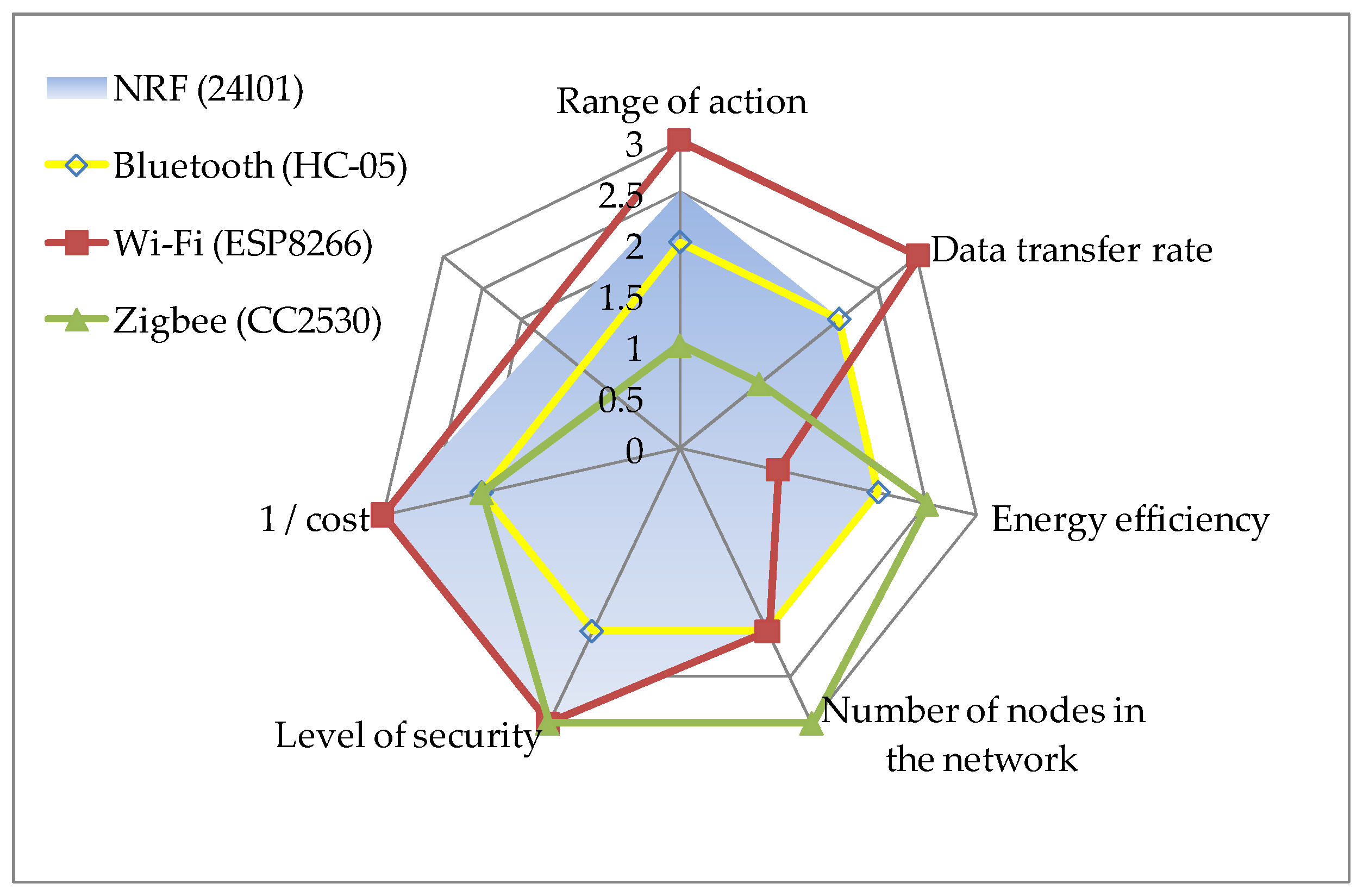
The advantages and disadvantages of each of the wireless modules are well illustrated by the petal diagram in Figure 5. The values of communication delays are not included in the table and the diagram. The duration of the communication delay (as a set of different delays) can be completely different, depending on the distance and power of the transmission, the amount of data, the transmission rate, and other reasons. Therefore, the study of this parameter will be conducted in the next section of the article. According to the three-point evaluation system, a score of “1” means bad and “3” means very good. Wi-Fi and nRF have the largest area of figures.
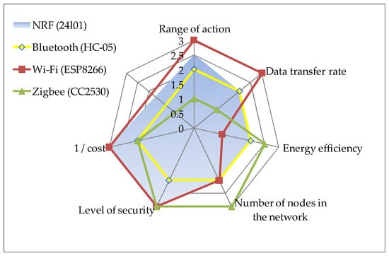
Figure 5.
Petal chart comparison of the selected performance parameters of wireless modules.
There may be several options for implementing wireless transmission of information between the secondary and the primary side. Neither are there hard rules for choosing a wireless network. It should be ensured that the information is transmitted without distortion and the connection is noise-resistant to electromagnetic disturbances. Only the integer type of data from the ADC needs to be transmitted from the secondary side. Therefore, the transfer of a significant amount of data is also not required and is not a priority. In addition, the modules should be energy efficient and not too expensive.
Currently, nRF modules are among the most affordable, efficient and quite acceptable in terms of energy consumption. NRF modules were chosen due to their good performance in the energy consumption, range, data security, as well as network capabilities for the transfer of measurement results to the primary side. The nRF24L01 modules operate in the Industrial, Scientific Medical radio band (ISM) at a frequency of 2.4 GHz. The 2.4 Ghz GSM band is free of charge and not subject to registration. They have a high data transfer rate of up to 2 Mbps, which is higher than the I2C and UART buses (nRF works through the SPI interface). The operation mode of the modules (receiver/transmitter) can be changed during their operation. The modules have high noise immunity, the data in the packets are accepted (received) with cyclic redundancy check (CRC) verification and control of data delivery. These modules also have a slight delay at the transmitting information, as shown in the next sections.
4. Case Study of the Proposed Control System with the Model of Communication Delay
4.1. Delays in the Feedback Circuits of a Closed-Loop Control System in the WPT
All network delays (equipment delay, transmission delay, and propagation delay) can be collectively referred to as a communication delay, as a total delay from the end of information transmission to the end of full reception of the data packet. The transmission delay determines the time required to transmit all bits of the frame in the packet.
Data on wireless networks may be sent at a slower rate or packets may be lost due to a number of conditions, most notably delays. As the distance between the modules increases, the signal strength decreases, which means that the signal-to-noise ratio decreases, leading to a deterioration in the performance of the wireless network [45].
Transmission delay extension can also occur due to poor signal quality or low power (due to attenuation or interference) [42]. A common reason is bandwidth limitation, which increases the time of physical transmission of frames through the module. Transmission delay limits the bandwidth of the channel, which determines the maximum sampling rate [42].
The delay time depends on the available minimum step size. For example, the time period of the switching cycle is 10 μS when the circuit is operating at a frequency of 100 kHz [15]. At least 100 steps per switching period should be available for acceptable performance and accuracy [15]. Accordingly, the minimum step size is 100 nS.
On the other hand, increasing the sampling rate has limitations. The experimental work by [46] showed that while faster sampling extended the range of stability with respect to the packet loss, higher sampling rates in turn produce higher rates of data loss for a given signal-to-noise ratio. The communication delays can destabilize the system if they are greater than the sampling period [2]. The data rate of a few hundred hertz is sufficient for a stable charging process, which is confirmed in this work.
It is not necessary to monitor the parameters with high frequency as there are no significant dynamics in wireless charging systems. Therefore, mathematical methods for estimating, eliminating and compensating for delays [2,47,48,49] in this case are residual solutions. In this case, the maximum allowable delay in the transmission of information at which the system will still work properly can be significant.
As a result, it will be sufficient to take into account all the delays as a total at the WPT system analysis in general by the transfer function. Next, investigation of the WPT system with different durations of total delay is required.
4.2. Mathematical Description and Modeling of a Closed-Loop WPT System Taking into Account the Delay Value
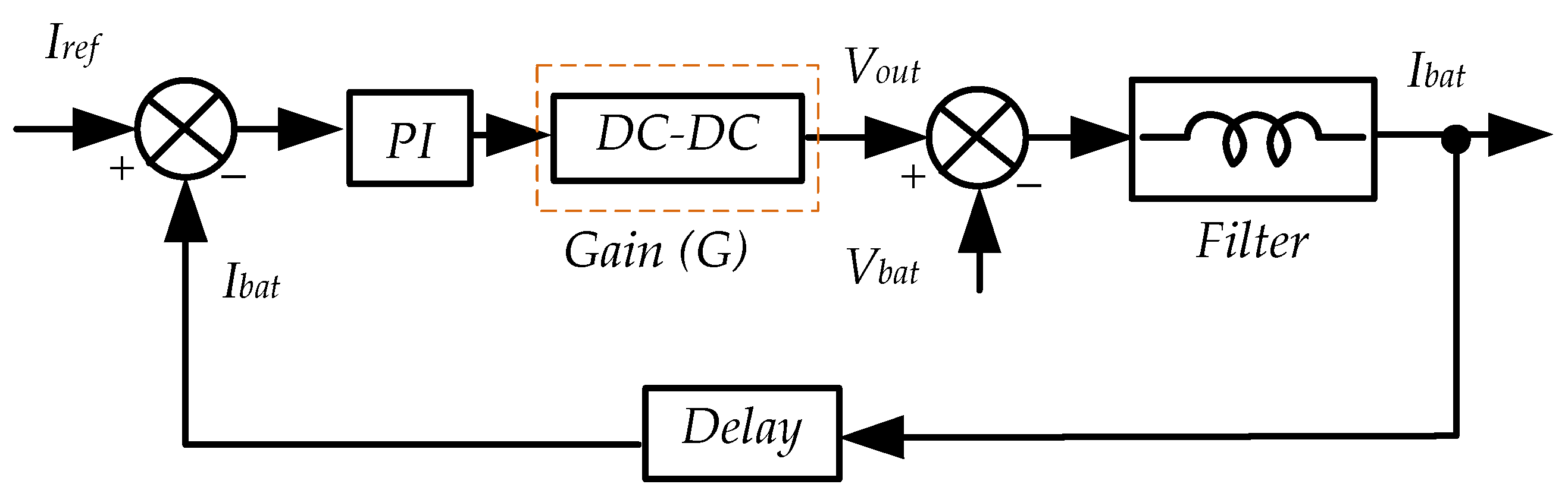
The control system was simplified for the mathematical analysis (Figure 6). By taking into account the significant difference in the dynamics of the transmitting system in comparison to the output filter, the model can be simplified. This will decrease model complexity while still the dynamics of the system would be precise enough. By using these dynamics relations, the high-frequency link with the high-frequency alternating current can be replaced by the gain G. With this simplification system, tuning is being concentrated on estimating the appropriate coefficients to maintain the filter inductor current on an appropriate level.
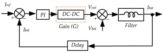
Figure 6.
Block diagram of the control system.
The reference battery current Iref is compared with the measured Ibat. The current error goes to the PI controller, which sends a signal to the equivalent DC-DC converter. This equivalent DC-DC converter is a result of merging the primary side dc-ac converter and secondary side rectifier. The output voltage will be as M ∗ G = Vout, where M is the modulation index of the primary side dc-ac inverter. The current Ibat is determined by the voltage difference between Vout and Vbat (ΔV ∗ gL = Ibat). This voltage is applied to L (inductive resistance of the output filter 1/sL). Finally, with a certain delay , the feedback signal arrives at the controller.
To obtain the mathematical model and to evaluate the coefficients of the controller, Laplace transform was used. As a result, the block diagram in Figure 6 has the following transfer function W(s):
where Kp, Ki—coefficients of PI-controller, G—gain of dc-dc transfer, L—filter inductance, Ts—sampling period, N—number of samples.
The simulation of the control system was carried out in order to obtain the coefficients of the regulator, to check the stability of the system at different delays with this function. The biggest component of the total delay will be the communication delay, as mentioned in the previous paragraph. This total delay will impose restrictions on the control system.
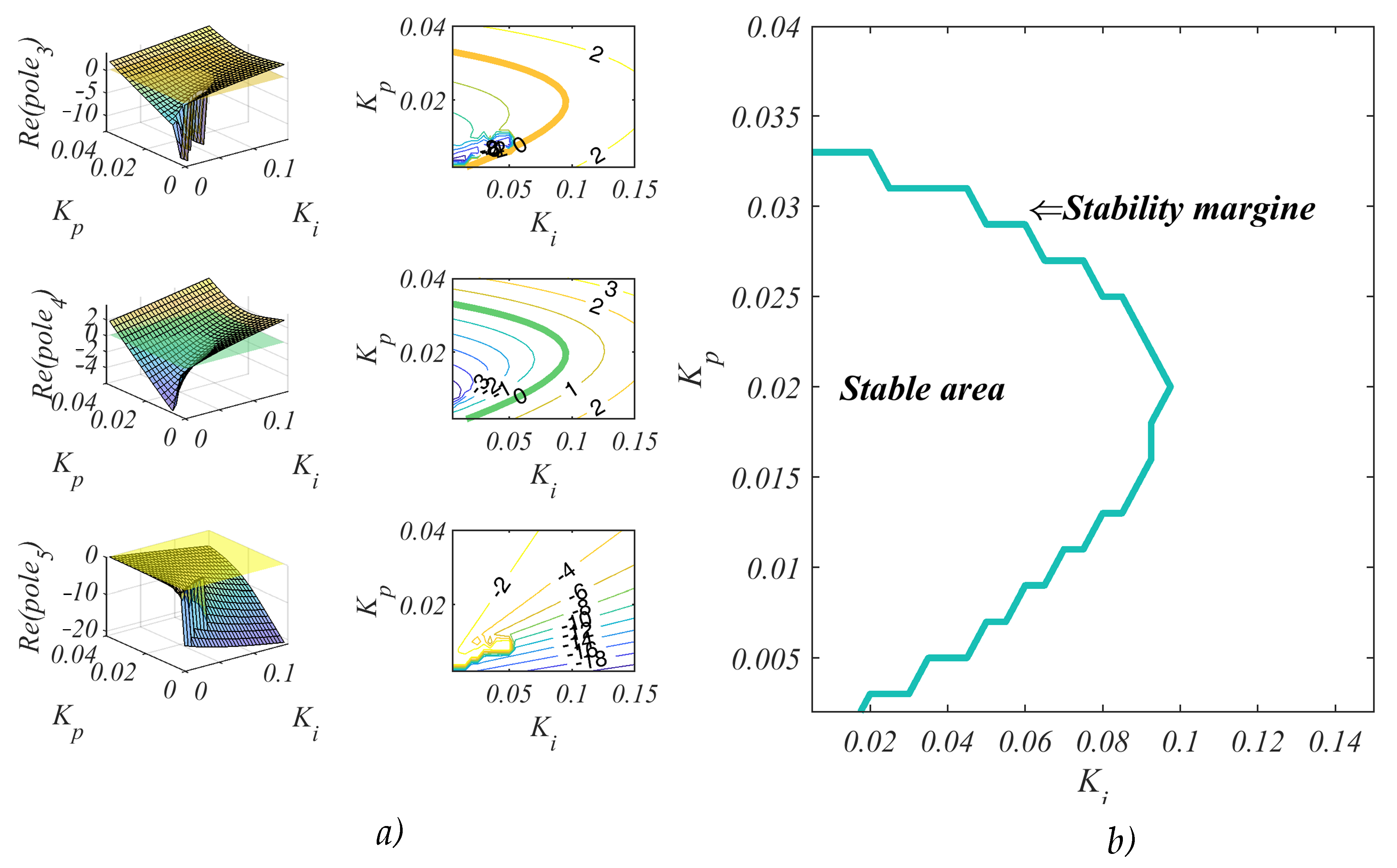
By taking the denominator of the model, poles for each of the controller coefficient combinations can be evaluated. Figure 7a represents the real part of each pole depending on these coefficients. The system will be unstable if the point is greater than zero. By taking all solutions below zero and merging these regions, the system stability margins can be estimated. Figure 7b shows the merged regions. The coefficient in this region can be chosen depending on the desired dynamics, overshoot level and minimal static error. The closer to the limit of stability, the faster can the regulator make an adjustment. However, there is a danger of fluctuations at the same time.
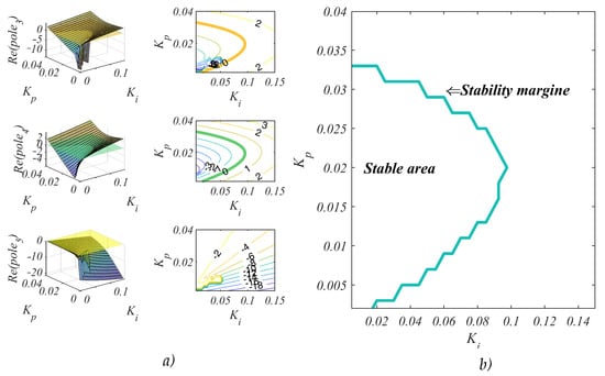
Figure 7.
Determination of controller coefficients combinations: (a) poles; (b) system stability margin.
This analytical method of adjusting the controller taking into account the transfer function at low frequency will be more accurate in contrast to the well-known Ziegler−Nichols method. In the case of the latter, the coefficients obtained after the preliminary calculation must be adjusted experimentally, often with very significant corrections.
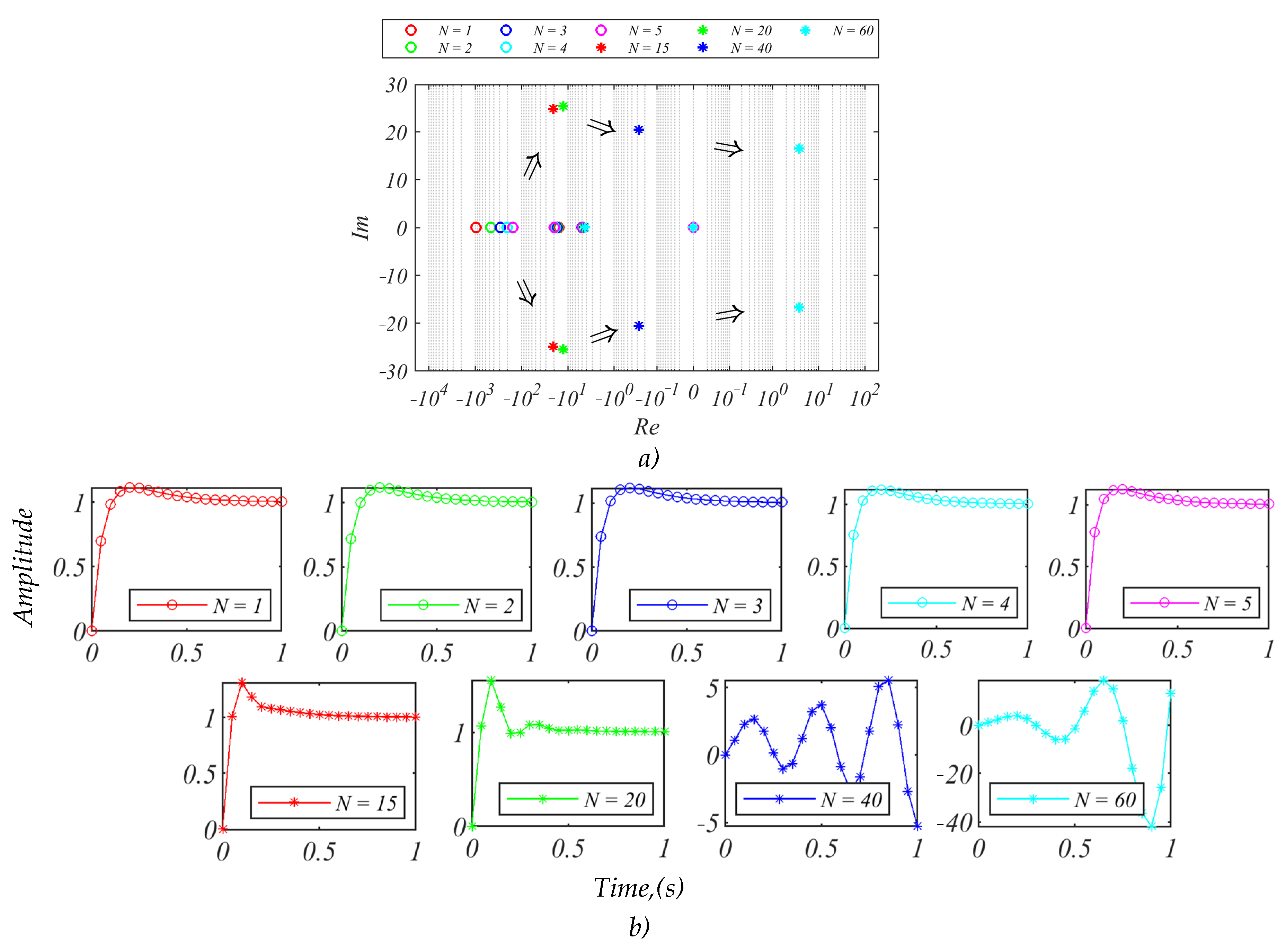
As the system had a valuable communication delay of the feedback signal, the stability was analyzed under different communication delays (Figure 8). By taking into account that the controller frequency was set to 500 Hz and by multiplying this step on N (number of samples), the stability was made for the range of delays. The complex plot in Figure 8a shows the poles of the system for different delays. The horizontal axis was plotted on a logarithmic scale because the poles were very scattered. At N ≤ 5, the single poles are on the Im axis, the system is stable, and the process is damped. It is seen that at N ≥ 15 with increasing delay, the complex-conjugate poles appeared and the oscillating process began.
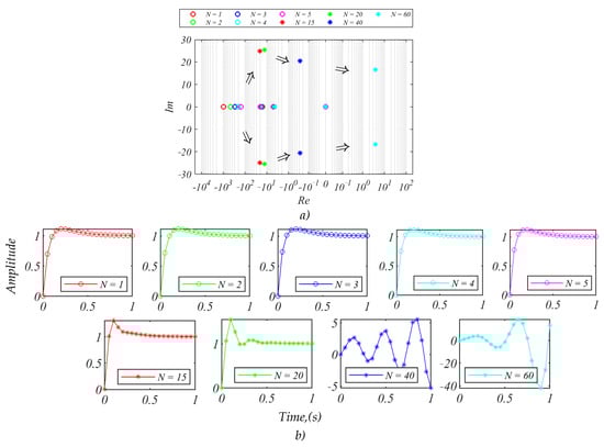
Figure 8.
Study of the control system with different delays: (a) poles of system; (b) dynamic response of the system to a single step.
Figure 8b shows the step response for different delays. The appearance of complex-conjugate poles for high communication delays before the moment when system became unstable should be noted. As can be seen, the system was still stable even for the delay being 10 times higher than the communication delay of the system.
Additionally, the system stability can be influenced by system component imperfections [50]. The analysis of this influence in the proposed model was carried out for the output filter accuracy in a range ± 8% and showed minor influences in comparison to the communicational delay.
Therefore, the control system implemented was based on the settings obtained from the simulation results.
4.3. Features and Implementation of the Proposed Control Strategy
The control algorithm based on the PI controller was implemented on a microcontroller TMS320F28375DPZPS from Texas Instruments. The TMS320F28375DPZPS is a powerful 32-bit microcontroller unit (MCU) with a floating-point unit and with dual-core architecture designed for advanced closed-loop control applications in real-time with improved performance.
The output voltage and current are monitored by using voltage and current sensors. In this WPT charger, the CV reference is 56.8 V, while the CC reference is 2 A.
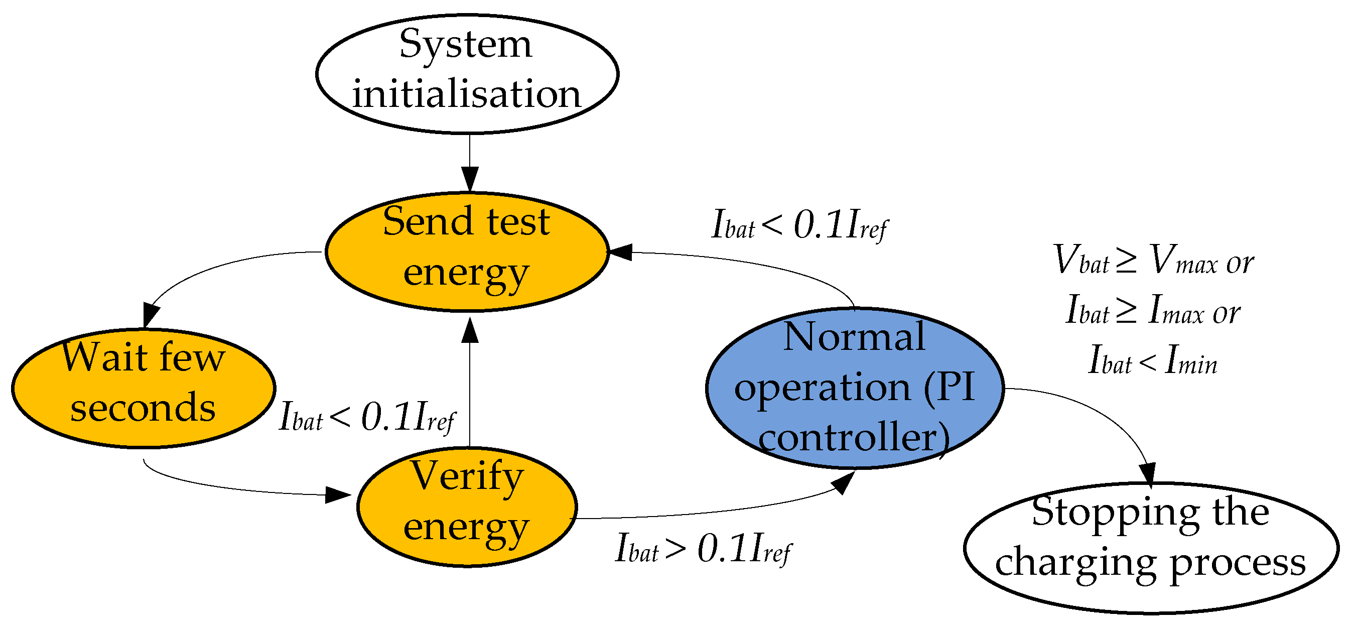
Firstly, the proposed algorithm is used for detecting the receiving coil (Figure 9). The structure of the program is implemented through a flag machine and has two main tasks. Before entering one of the tasks, first there is an initialization of interrupts on the timer, radio module and other peripherals.
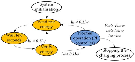
Figure 9.
Graphs of the secondary coil detection algorithm.
Then the test energy is sent for one second and the PWM signal is turned off. After that, for a few seconds, the system is waiting for the voltage and current data response of the secondary side and the analysis of the values is held. If the battery output charging current Ibat is less than 0.1Iref (i.e., the charging current on the battery is not sufficient), the system repeats this procedure for detecting the coil. This means that the secondary coil is missing, or the coupling coefficient is insufficient due to the large distance between the coils or the lateral displacement.
If the output charging current is more than 0.1Iref (10% from the reference charging current), the flag machine will start the normal operation of the PI controller to implement the CC or CV modes. In this task, at any time, if the Ibat change is less than 0.1Iref, and this battery is not fully charged, the detection of the secondary coil is resumed to enter normal cyclic operation and continue the charging process.
After the system initialization and start and successful check for the presence of the secondary coil and the conditions of allowable efficiency, the graph enters into the task of normal operation of the PI-controller (Figure 10). The measured battery output charging voltage Vbat and the current Ibat are acquired via voltage and current sensors and sent to the primary controller. In all cases, all data from the secondary side are firstly filtered (averaged) using the moving average method.
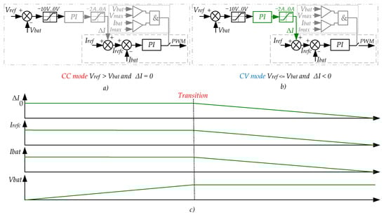
Figure 10.
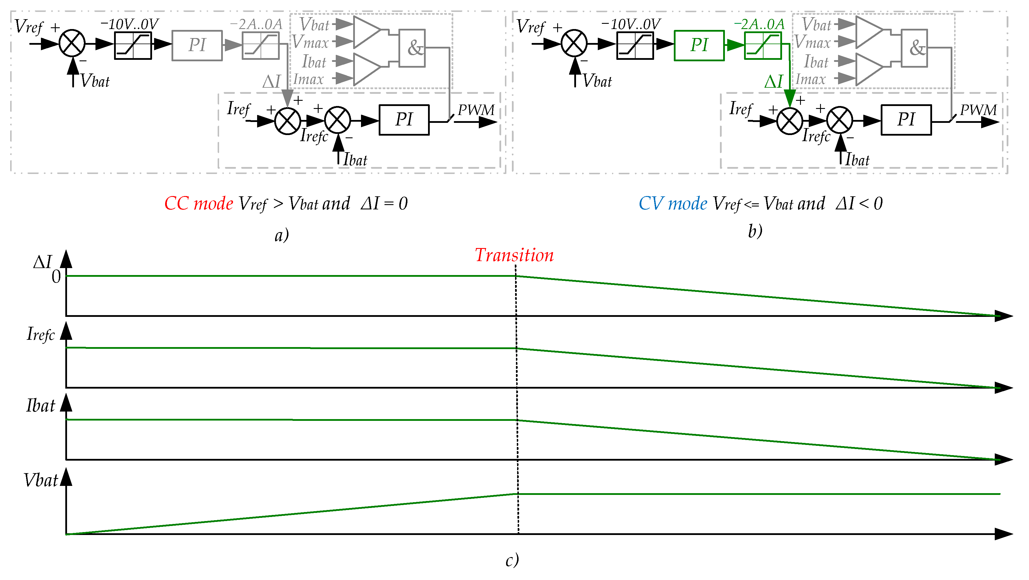
Proposed PI-based control strategy: (a) CC mode; (b) CV mode; (c) controller operation time diagram.
The CC/CV control system is built around the cascade PI controller (Figure 10a,b). The first controller is used to maintain the output current on an appropriate level. The second controller is activated when the charging system should switch to the CV mode. As can be seen, the output of the second controller is used as the value at which the reference current Irefc should be decreased to obtain necessary output voltage (Figure 10b,c). Such an approach is more convenient than the separate usage of controllers for CC and CV modes, as in this case, the CC controller is working during all operation modes and maintains the dynamics of the system on one level.
The operation mode begins with the CC mode (Figure 10a). As the value Vbat is lower than Vref, the input of the CV controller is zero and the output value ΔI is also zero. In this case, Iref = Irefc. As soon as Vbat becomes higher than Vref, the CV mode is activated (Figure 10b,c). The second controller is being activated and its output (ΔI) decreases the reference current Irefc = Iref + ΔI.
It should be noted that in addition, for safety, maximum current and voltage limiters are implemented. As soon as the voltage or the current overflows this margin, the power transmitting is stopped.
The charging process is finished when the output charging current reaches its minimum value (10% from the current value in the CC mode) or the output charging current or the voltage suddenly exceeds the maximum allowable charging current.
A series of experimental studies were conducted to confirm and verify the operation of the control system for wireless charging.
5. Experimental Verification of a Closed-Loop WPT System
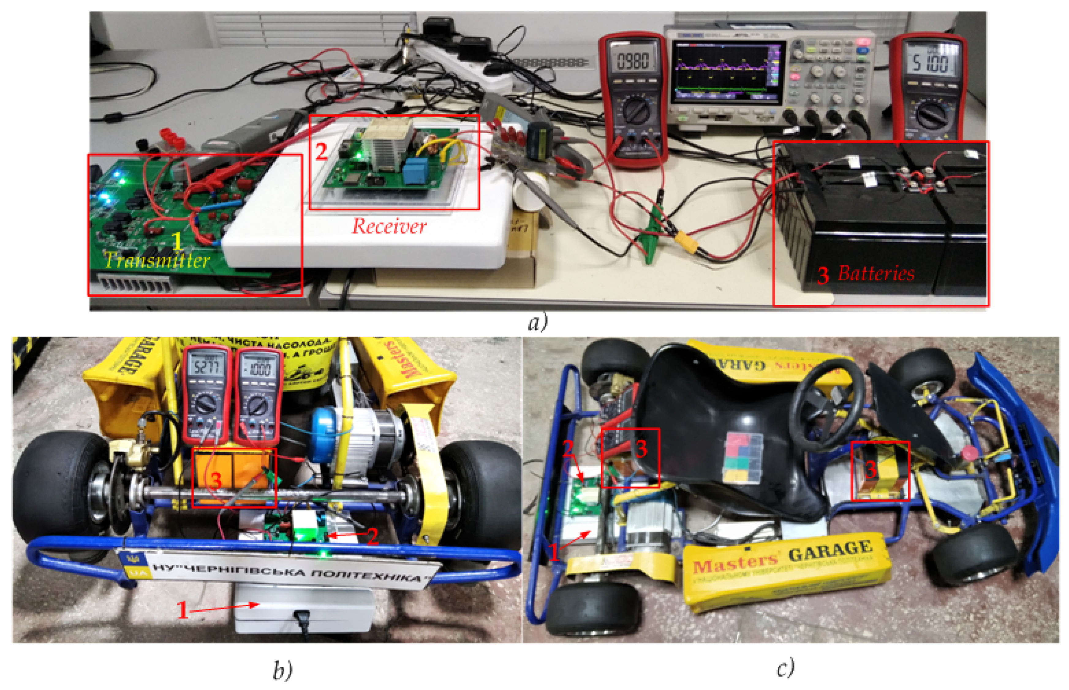
Experimental verification of the study results were obtained using a prototype of the wireless charging system presented in Figure 11. Firstly, experiments were conducted in the laboratory environment (Figure 11a). Finally, wireless charging of low-voltage batteries was installed on an electric kart ELECTRO ONE developed in Chernihiv Polytechnic National University (Figure 11b,c).

Figure 11.
Prototype of wireless charging: (a) during the laboratory tests; (b,c) implemented on the electric kart.
The maximum speed was 45 km/h. The speed limit of each mode was 16, 25 and 45 km/h, respectively. The electric kart can travel up to 35 km from a single battery charge. The kart was equipped with an electric motor Voltabikes-Brushless dc motor (BLDC), 48 V with a built-in planetary gearbox. The power of the electric motor was 1 kW.
The primary circuit board was designed with the ability to operate up to several hundred watts. In particular, greater distances between nets on the printed circuit board are provided for this purpose. Therefore, it had relatively large overall dimensions. The primary part woulf not be located on the vehicle, so the overall dimensions were not critical.
The N-channel SiC transistors C3M0030090K were used (900 V, 30 mΩ). The transistors provided switching at a frequency of 150 kHz (Table 3). Power was supplied to the primary part of the device from an alternating current grid of 220 V.
Table 3.
Key parameters of experimental setup.
The four Master 6-DZM-22.2 acid-lead maintenance-free batteries with a voltage of 12 V were connected in series to obtain a nominal voltage of 48 V. These were improved batteries using modern nanotechnology of graphene and silicone gel with capacitance 22.2 Ah. For comparison, other batteries, Luxeon LT9 (9 Ah), were also charged with lower currents. The charging current limit in these hermetic lead-acid batteries is only 1.5 A, so the maximum charging power is about 77 W.
All batteries were discharged to a voltage of 46 V in no-load mode before the start of the charging experiments. Deep discharge during the experiments and operation should be avoided in order to extend the life cycle of batteries.
The results obtained by experiments, input and output voltage and current waveforms, in both operation modes, CC and CV are presented in Figure 12. The inverter current waveform (I_in) had oscillations of a certain shape in the CV mode and did not have a pronounced peak and sinusoidal shape because it contained a large amount of high-order harmonics [27]. The fundamental reason for this problem was the response of the input impedance to the operating frequency, as noted in [27].
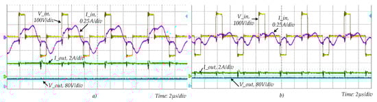
Figure 12.
Voltage and current waveforms in CC and CV modes: (a) voltage and current in the inverter (V_in, I_in) and battery charging voltage and current (V_out, I_out) in the CC mode at Rbat = 27 Ω; (b) voltage and current in the inverter (V_in, I_in) and battery charging voltage and current (V_out, I_out) in the CV mode at Rbat = 95 Ω.
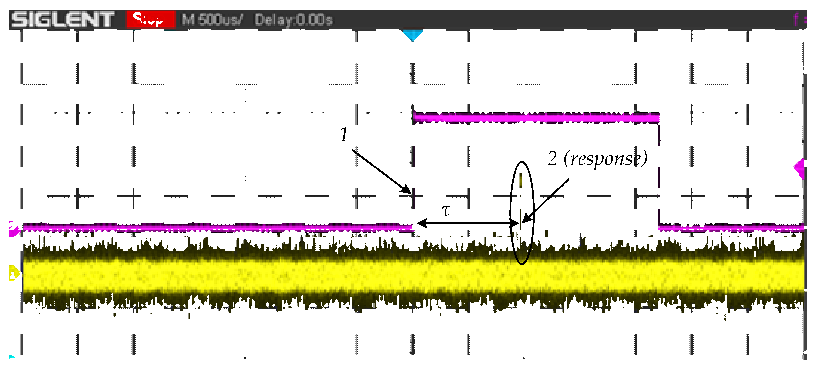
The transmission delay was determined also at the debugging of a closed–loop control system. The communication delay of the feedback system was about 1 ms, according to the test experimental oscillograms (Figure 13).

Figure 13.
Communication delay of the feedback system (τ), where curve 1 is the information signal from the secondary side, curve 2 is the response on the primary side.
It was confirmed that the equivalent resistance of a battery increases with the charging time and reaches a maximum when the battery is fully charged (Figure 4 and Figure 14e), as reported in [27,32,33,34]. Equivalent resistance Rbat of the batteries equals the ratio of the charging voltage Vbat and the charging current Ibat (Rbat = Vbat/Ibat). The battery load of IPT charging systems acts as an equivalent variable resistance Rbat, which is the rate of the charging voltage over the charging current [32].
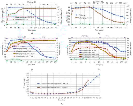
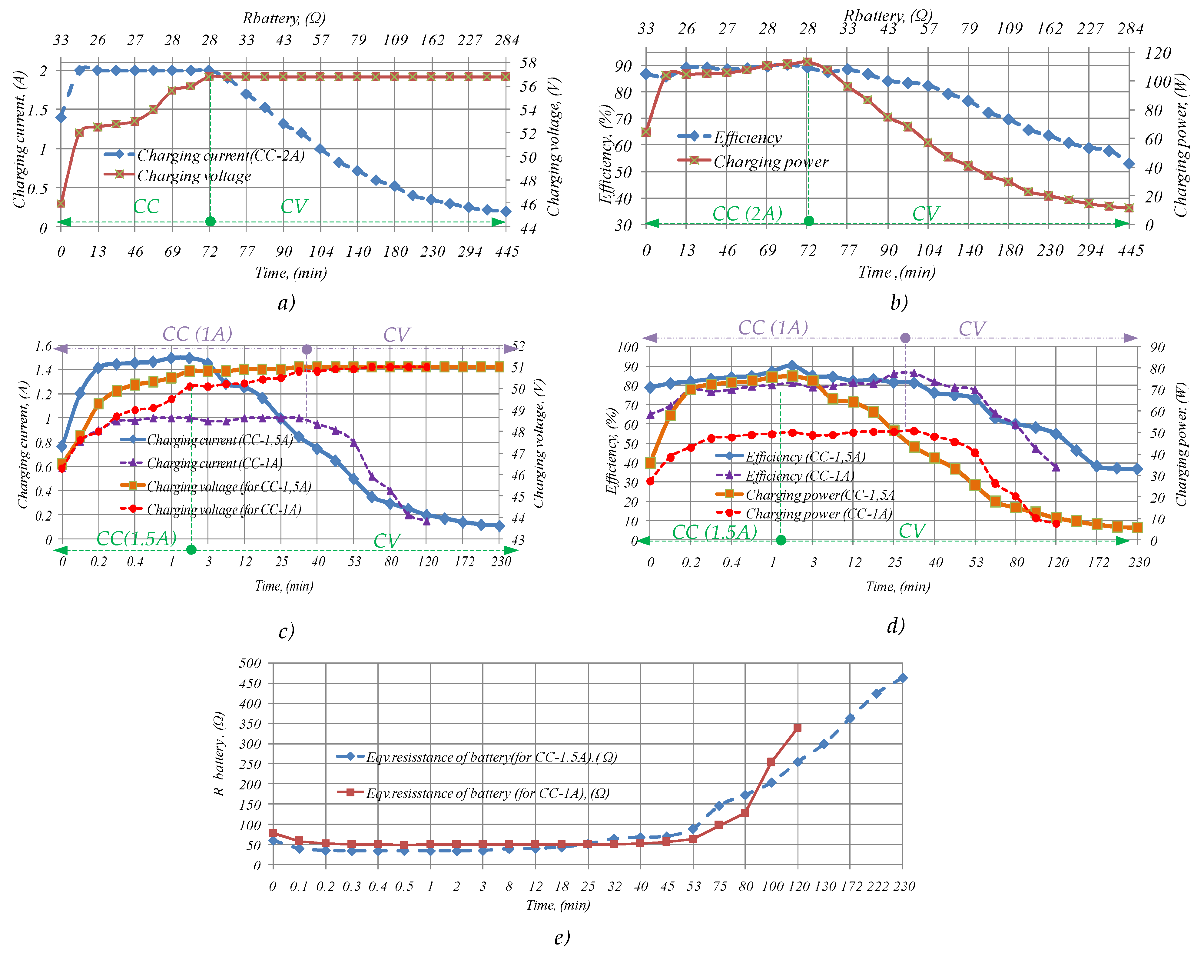
Figure 14.
Experimental dependences in the CC and CV modes for different batteries: (a) charging profile versus charging time and equivalent resistance of batteries at charging current 2 A in the CC mode; (b) efficiencies and output power of the WPT system at charging current 2 A in the CC mode; (c) charging profile versus charging time and equivalent resistance of batteries at charging current 1.5 A and 1 A in the CC mode; (d) efficiencies and output power of the WPT system at charging current 1.5 A and 1 A in the CC mode; (e) equivalent resistance of batteries versus charging time for charging current 1.5 A and 1 A in the CC mode.
The equivalent resistance of the batteries increased to 28 Ω in the CC mode (Figure 14a) and the voltage on the batteries reached a nominal value of 56.8 V. The battery charge time in the CC mode was 73 min. Figure 14b shows the change in the efficiency depending on the charging time. The maximum efficiency was 90.5% and did not decrease too much. The overall maximum DC-DC efficiency was 84%, taking into account the losses on the control system. The efficiency of the system could be slightly higher with higher transmission power. First of all, it is achieved by reducing the contribution of control losses to the total system losses.
From that point, the system automatically started charging in the CV mode. The maximum (88%) efficiency in the CV mode was slightly lower than in the CC mode, as expected. The oscillation of the charging voltage in the CV mode was less than 1%, which indicates excellent performance of the controller (Figure 12). In the CV mode, the minimum charging current is set, at which the charging process ends automatically. This is 10% of the maximum charging current, i.e., 0.2 A in this case. The equivalent resistance of the batteries at the end of the charging process was 284 Ω, the charging power dropped to 11.4 W, and the efficiency decreased to 53%.
The duration of charging in the CV mode was 6.2 h, which is certainly longer than charging with maximum current. The total duration of the wireless charging process was 7.5 h, which corresponded to the declared characteristics of the batteries.
Figure 14c,d shows the charging time of other batteries, Luxeon LT9 (9 Ah), with a charging current of 1.5 and 1 A. The duration of the CV mode was significantly reduced due to the longer duration of operation in the CC mode. This shows that in practice, it is more appropriate to charge the batteries not with the maximum current, but slightly lower. This will reduce the total charging time (from 230 to 120 min). The efficiency of the system may be slightly lower. The main results are shown in the comparative Table 4. It should be noted that no new batteries were used for the experiment. They had already lost part of their capacity after intensive operation, so the charge−discharge processes occurred fairly quickly.
Table 4.
Comparison of performance of different wireless chargers solutions.
The obtained results have values similar to those of existing solutions (Table 4). The maximum efficiency in both operating modes and charging time are not worse than other developed laboratory analogues, and in the range from 90 to 850 W, as can be seen from Table 4.
No commercial analogues of wireless chargers were found in a similar range of charging power and with power supply from the household network and an output voltage of 48 V. Therefore, it is not possible to compare the efficiency with the designed device. Only as an example, the maximum efficiency of wireless chargers for mobile phones is up to 80–85% on average at a power of 10–20 W. The maximum efficiency can be higher on average, around 90% in commercial serial wire analogues of this device with a power of 75 W or more. These values prove that the developed wireless charger with a new topology and the proposed control system with improved mass-dimensional parameters of the magnetic part has the same level of efficiency as commercial low-power wired and wireless devices. This perspective paves the way for the implementation of such devices.
The proposed control system is the simplest compared to the solution presented in Table 4, in addition, the advantage is also a method and algorithm for detecting the presence of the receiving coil. The magnetic part of the system has reduced mass-dimensional parameters, in contrast to the solutions presented in Table 4 and the vast majority of existing solutions. With minor modifications, this wireless charger can be adapted to charge batteries of other voltages and power levels.
6. Conclusions
The main contribution of this study is the development of a simple closed-loop control system with time-delay constraints for a wireless charger of low-voltage energy storage devices of low-power electric vehicles. This charger is suitable for the implementation of CC/CV modes in dual T-type SiC-based inverter and split transmission coils. Therefore, this system was firstly proposed, used and studied together with the developed control system with a communication delay for charging low-voltage batteries, which proves its effectiveness and feasibility in wireless chargers.
The optimal structure for the control of the low-power WPT system was selected as a result of reviewing and analyzing the existing solutions. The analysis of different wireless data networks and modules was conducted for feedback implementation, resulting in the selected nRF module as the best solution that has a low communication delay.
The transfer function of the control system was obtained and the coefficients of the controller were determined (the controller is adjusted) with the help of Laplace transform. The dynamic reaction of the system to a single jump was investigated at different delays. It was established that the system was still stable for a delay 10 times higher than the communication delay of the system, that is, with a delay of no more than 20 ms. Despite the fact that system linearization was made, the provided model was sufficient to estimate the control system parameters and verify them in an experimental section. Additionally, the influence of system stability was made for the different accuracies of output filter. These results show that in the provided system with a valuable communication delay, the influence of component accuracy on system stability is minor and can be neglected.
The proposed new algorithm for detecting the secondary coil increases the functionality, safety and usability of the wireless charger. In turn, this will always allow working at high efficiency, though in a smaller range of distances between coils. This solution reduces the reactive current circulating in the elements of the primary side, and thus may increase the reliability of the entire system and the durability of the electronic components. To increase the safety of battery charging, we implemented the automatic stop to the charging process in the normal mode and immediate stop in emergency modes (overvoltage and overcurrent protection). The entire magnetic part of the wireless charger system has reduced mass-dimensional parameters, which are facilitated by the proposed circuit (T-type inverter together with split transmission coils and with SP compensation).
An experimental prototype of the wireless charger was implemented and studied to test and confirmed the proposed control approach. The experimental results obtained complied with the existing solutions. The maximum transmission power was 113 W at the charging current 2 A. The maximum efficiency in the CC mode was reached at 90.5%, in CV, at 88%. The charging voltage oscillation in the CV mode was less than 1%, which indicates the desired performance of the controller. The total charging time was 7.5 h, which is normal according to the passport data on the batteries. The experimentally measured communication delay was 1 ms, which is several times lower than the instability limit.
7. Patents
Ukrainian patent No. 142050 “Wireless power transfer system based on three-level T-type inverter and two coupled transmission coils”.
Author Contributions
Idea, supervising: O.H.; theoretical review and software: B.P., O.M.; experiments and writing of article: V.S.; PCB design: O.V.; technical advice and experiments: O.L.; revising: J.L.; final editing, revising: J.Z. All authors have read and agreed to the published version of the manuscript.
Funding
This research and paper was funded by Ukrainian Ministry of Education and Science (Grants №0117U007260 “A highly effective system for low-voltage charging of low-voltage accumulators” and №0118U003865 “High-efficient wireless power transfer systems based on new semiconductor converters topologies”); Integrated Programme of Development of Gdansk University of Technology (POWR.03.05.00-00-Z044/17), Research grant for young scientists (Gdansk University of Technology), LINTE^2 Laboratory and Latvian Council of Science project No. lzp-2020/2-0252.
Institutional Review Board Statement
Not applicable.
Informed Consent Statement
Not applicable.
Conflicts of Interest
The authors declare no conflict of interest.
References
- Shevchenko, V.; Pakhaliuk, B.; Husev, O.; Veligorskyi, O.; Stepins, D.; Strzelecki, R. Feasibility study GaN transistors application in the novel split-coils inductive power transfer system with T-type inverter. Energies 2020, 13, 4535. [Google Scholar] [CrossRef]
- Dhand, R.; Lee, G.; Cole, G. Communication delay modeling and its impact on real-time distributed control systems. In Proceedings of the International Conference on Advanced Engineering Computing and Applications in Science, Florence, Italy, 25–30 October 2010; pp. 39–46. [Google Scholar]
- Anthon, A.; Zhang, Z.; Andersen, M.A.E.; Holmes, D.G.; McGrath, B.; Teixeira, C. The Benefits of SiC mosfets in a T-Type Inverter for Grid-Tie Applications. IEEE Trans. Power Electron. 2017, 32, 2808–2821. [Google Scholar] [CrossRef] [Green Version]
- Pakhaliuk, B.; Husev, O.; Shevchenko, V.; Zakis, J.; Khomenko, M.; Strzelecki, R. Modified inductive multi-coil wireless power transfer approach based on z-source network. IEEE J. Emerg. Sel. Top. Power Electron. 2020, 1. [Google Scholar] [CrossRef]
- Avci, E.; Uçar, M. Analysis and design of grid-connected 3-phase 3-level AT-NPC inverter for low-voltage applications. Turk. J. Electr. Eng. Comput. Sci. 2017, 25, 2464–2478. [Google Scholar] [CrossRef]
- Gurpinar, E.; Castellazzi, A. Single-phase T-type inverter performance benchmark using Si IGBTs, SiC MOSFETs, and GaN HEMTs. IEEE Trans. Power Electron. 2015, 31, 7148–7160. [Google Scholar] [CrossRef]
- Ma, C.-T.; Gu, Z.-H. Review of GaN HEMT applications in power converters over 500 W. Electronics 2019, 8, 1401. [Google Scholar] [CrossRef] [Green Version]
- Aksamit, W.; Rzeszutko, J. Application of GaN transistors to increase efficiency of switched-mode power supplies. Zesz. Nauk. Wydziału Elektrotech. Autom. Politech. Gdańskiej 2016, 49, 11–16. [Google Scholar]
- Wang, B.; Dong, S.; Jiang, S.; He, C.; Hu, J.; Ye, H.; Ding, X. A Comparative study on the switching performance of GaN and Si power devices for bipolar complementary modulated converter legs. Energies 2019, 12, 1146. [Google Scholar] [CrossRef] [Green Version]
- Shevchenko, V.; Husev, O.; Strzelecki, R.; Pakhaliuk, B.; Poliakov, N.; Strzelecka, N. Compensation topologies in IPT systems: Standards, requirements, classification, analysis, comparison and application. IEEE Access 2019, 7, 120559–120580. [Google Scholar] [CrossRef]
- Bosshard, R.; Kolar, J.W.; Mühlethaler, J.; Stevanović, I.; Wunsch, I.B.; Canales, F. Modeling and η-α-pareto optimization of inductive power transfer coils for electric vehicles. IEEE J. Emerg. Sel. Top. Power Electron. 2015, 3, 50–64. [Google Scholar] [CrossRef]
- Li, Z.; Song, K.; Jiang, J.; Zhu, C. Constant current charging and maximum efficiency tracking control scheme for supercapacitor wireless charging. IEEE Trans. Power Electron. 2018, 33, 9088–9100. [Google Scholar] [CrossRef]
- Yeo, T.-D.; Kwon, D.; Khang, S.-T.; Yu, J.-W. Design of maximum efficiency tracking control scheme for closed-loop wireless power charging system employing series resonant tank. IEEE Trans. Power Electron. 2017, 32, 471–478. [Google Scholar] [CrossRef]
- Pellitteri, F.; Di Tommaso, A.O.; Miceli, R. Investigation of inductive coupling solutions for E-bike wireless charging. In Proceedings of the 50th International Universities Power Engineering Conference (UPEC), Stoke on Trent, UK, 1–4 September 2015; pp. 1–6. [Google Scholar] [CrossRef]
- Al-Hitmi, M.A.; Iqbal, A.; Rahman, S.; Maroti, P.K.; Meraj, M.; Mehrjerdi, H. A dual active bridge based wireless power transfer system for EV battery charging controlled using high speed FPGA. In Proceedings of the 2020 IEEE International Conference on Informatics, IoT, and Enabling Technologies (ICIoT), Doha, Qatar, 2–5 February 2020; pp. 372–376. [Google Scholar] [CrossRef]
- Nutwong, S.; Sangswang, A.; Naetiladdanon, S. Output voltage control of the SP topology IPT system using a primary side controller. In Proceedings of the 13th International Conference on Electrical Engineering/Electronics, Computer, Telecommunications and Information Technology (ECTI-CON), Chiang Mai, Thailand, 28 June–1 July 2016. [Google Scholar]
- Koh, K.E.; Beh, T.C.; Imura, T.; Hori, Y. Impedance matching and power division using impedance inverter for wireless power transfer via magnetic resonant coupling. IEEE Trans. Ind. Appl. 2013, 50, 2061–2070. [Google Scholar] [CrossRef]
- Li, H.; Li, J.; Wang, K.; Chen, W.; Yang, X. A Maximum Efficiency Point Tracking Control Scheme for Wireless Power Transfer Systems Using Magnetic Resonant Coupling. IEEE Trans. Power Electron. 2015, 30, 3998–4008. [Google Scholar] [CrossRef]
- Ozawa, Y.; Sekiya, H. Implementation and evaluation of pre- and post-regulation control with class-e2 wireless power transfer system. In Proceedings of the 2017 IEEE International Telecommunications Energy Conference (INTELEC), Broadbeach, Australia, 22–26 October 2017; pp. 369–375. [Google Scholar]
- Femia, N.; Di Capua, G.; Lisi, G. Power vs efficiency analysis in high-frequency wireless power transfer systems—Part I: Model. In Proceedings of the 2016 IEEE 2nd International Forum on Research and Technologies for Society and Industry Leveraging a Better Tomorrow (RTSI), Bologna, Italy, 7–9 September 2016; pp. 1–5. [Google Scholar]
- Diekhans, T.; De Doncker, R.W. A Dual-side controlled inductive power transfer system optimized for large coupling factor variations and partial load. IEEE Trans. Power Electron. 2015, 30, 6320–6328. [Google Scholar] [CrossRef]
- Pellitteri, F.; Boscaino, V.; Di Tommaso, A.O.; Miceli, R.; Capponi, G. Wireless battery charging: E-bike application. In Proceedings of the 2013 International Conference on Renewable Energy Research and Applications (ICRERA), Madrid, Spain, 20–23 October 2013; pp. 247–251. [Google Scholar]
- Pamungkas, L.; Tampubolon, M.; Lin, Q.; Chiu, H.-J. Performance comparison of primary side PFM and secondary side PWM for SS wireless power transfer CC/CV control strategy. In Proceedings of the 2018 IEEE International Power Electronics and Application Conference and Exposition (PEAC), Shenzhen, China, 4–7 November 2018; pp. 1–5. [Google Scholar]
- Coppola, M.; Cennamo, P.; Dannier, A.; Iannuzzi, D.; Meo, S. Wireless Power Transfer circuit for e-bike battery charging system. In Proceedings of the 2018 IEEE International Conference on Electrical Systems for Aircraft, Railway, Ship Propulsion and Road Vehicles & International Transportation Electrification Conference (ESARS-ITEC), Nottingham, UK, 7–9 November 2018; pp. 1–5. [Google Scholar]
- Liu, F.; Chen, K.; Zhao, Z.; Li, K.; Yuan, L. Transmitter-side control of both the CC and CV modes for the wireless EV charging system with the weak communication. IEEE J. Emerg. Sel. Top. Power Electron. 2017, 6, 955–965. [Google Scholar] [CrossRef]
- Chen, Y.; Kou, Z.; Zhang, Y.; He, Z.; Mai, R.; Cao, G.-Z. Hybrid topology with configurable charge current and charge voltage output-based WPT charger for massive electric bicycles. IEEE J. Emerg. Sel. Top. Power Electron. 2018, 6, 1581–1594. [Google Scholar] [CrossRef]
- Chen, Y.; Yang, N.; Yang, B.; Dai, R.; He, Z.; Mai, R.; Gao, S. Two-/three-coil hybrid topology and coil design for WPT system charging electric bicycles. IET Power Electron. 2019, 12, 2501–2512. [Google Scholar] [CrossRef]
- Bosshard, R.; Badstubner, U.; Kolar, J.W.; Stevanovic, I. Comparative evaluation of control methods for Inductive Power Transfer. In Proceedings of the 2012 International Conference on Renewable Energy Research and Applications (ICRERA), Nagasaki, Japan, 11–14 November 2012; pp. 1–6. [Google Scholar]
- Omomo, A.; Takaoka, N.; NamLe, H.; Kusaka, K.; Itoh, J. T-type NPC inverter with active power decoupling capability using discontinuous current mode. In Proceedings of the 20th European Conference on Power Electronics and Applications (EPE’18 ECCE Europe), Riga, Latvia, 17–21 September 2018; pp. 1–10. [Google Scholar]
- İnci, M. Performance analysis of T-type inverter based on improved hysteresis current controller. Balk. J. Electr. Comput. Eng. 2019, 7, 149–155. [Google Scholar] [CrossRef]
- Tran, H.N.; Nguyen, T.D. Predictive voltage controller for T-type NPC inverter. In Proceedings of the 2016 IEEE Region 10 Conference (TENCON), Singapore, 22–25 November 2016; pp. 305–310. [Google Scholar] [CrossRef]
- Mai, R.; Chen, Y.; Li, Y.; Zhang, Y.; Cao, G.-Z.; He, Z. Inductive power transfer for massive electric bicycles charging based on hybrid topology switching with a single inverter. IEEE Trans. Power Electron. 2017, 32, 5897–5906. [Google Scholar] [CrossRef]
- Chen, Y.; Zhang, H.; Park, S.-J.; Kim, D.-H. A switching hybrid LCC-S compensation topology for constant current/voltage EV wireless charging. IEEE Access 2019, 7, 133924–133935. [Google Scholar] [CrossRef]
- Bottigheimer, M.; Parspour, N.; Maier, S. Design of an intrinsically safe inductive charging system against offset for low voltage onboard supply systems in lightweight construction electrical vehicles. In Proceedings of the 2018 International Symposium on Power Electronics, Electrical Drives, Automation and Motion (SPEEDAM), Amalfi, Italy, 20–22 June 2018; pp. 742–749. [Google Scholar] [CrossRef]
- Wei, Z.; Zhao, J.; Xiong, R.; Dong, G.; Pou, J.; Tseng, K.J. Online estimation of power capacity with noise effect attenuation for lithium-ion battery. IEEE Trans. Ind. Electron. 2019, 66, 5724–5735. [Google Scholar] [CrossRef]
- Wei, Z.; Dong, G.; Zhang, X.; Pou, J.; Quan, Z.; He, H. Noise-immune model identification and state-of-charge estimation for lithium-ion battery using bilinear parameterization. IEEE Trans. Ind. Electron. 2021, 68, 312–323. [Google Scholar] [CrossRef]
- Wei, Z.; He, H.; Pou, J.; Tsui, K.-L.; Quan, Z.; Li, Y. Signal-disturbance interfacing elimination for unbiased model parameter identification of lithium-ion battery. IEEE Trans. Ind. Informat. 2021, 17, 5887–5897. [Google Scholar] [CrossRef]
- Zhang, M.; Tan, L.; Li, J.; Huang, X. The charging control and efficiency optimization strategy for WPT system based on secondary side controllable rectifier. IEEE Access 2020, 8, 127993–128004. [Google Scholar] [CrossRef]
- Liu, J.; Xu, W.; Chan, K.W.; Liu, M.; Zhang, X.; Chan, N.H.L. A three-phase single-stage AC–DC wireless-power-transfer converter with power factor correction and bus voltage control. IEEE J. Emerg. Sel. Top. Power Electron. 2020, 8, 1782–1800. [Google Scholar] [CrossRef]
- Pellitteri, F.; Campagna, N.; Castiglia, V.; Damiano, A.; Miceli, R. Design, implementation and experimental results of a wireless charger for E-bikes. In Proceedings of the 2019 International Conference on Clean Electrical Power (ICCEP), Otranto, Italy, 2–4 July 2019; pp. 364–369. [Google Scholar] [CrossRef]
- Gil, A.; Sauras-Perez, P.; Taiber, J. Communication requirements for Dynamic Wireless Power Transfer for battery electric vehicles. In Proceedings of the 2014 IEEE International Electric Vehicle Conference (IEVC), Florence, Italy, 16–19 December 2014; pp. 1–7. [Google Scholar] [CrossRef]
- Scanlon, W.G. An overview of wireless networks in control and monitoring. In Computational Intelligence; Huang, D.S., Li, K., Irwin, G.W., Eds.; Springer: Berlin/Heidelberg, Germany, 2016; Volume 4114. [Google Scholar] [CrossRef]
- Li, Y.; Duan, Q.; Zou, Y. High robustness control for robotic wireless power transfer systems with multiple uncertain parameters using a virtual buck converter. Energies 2017, 10, 517. [Google Scholar] [CrossRef] [Green Version]
- Chao, C.; Shieh, J. Solar energy powered bicycle for wireless supervisory control and remote power management applications. In Proceedings of the 2010 International Conference on Electrical Machines and Systems, Incheon, Korea, 10–13 October 2010; pp. 660–663. [Google Scholar]
- Ploplys, N.; Kawka, P.; Alleyne, A. Closed-loop control over wireless networks. IEEE Control. Syst. 2004, 24, 58–71. [Google Scholar] [CrossRef]
- Willig, A.; Kubisch, M.; Hoene, C.; Wolisz, A. Measurements of a wireless link in an industrial environment using an IEEE 802.11-compliant physical layer. IEEE Trans. Ind. Electron. 2002, 49, 1265–1282. [Google Scholar] [CrossRef] [Green Version]
- Wang, Z.; Fukushima, S. Control strategy for networked control systems with time delay and packet dropout using linear matrix inequalities. EURASIP J. Wirel. Commun. Netw. 2020, 2020, 1–11. [Google Scholar] [CrossRef]
- Heemels, W.P.M.H.; Teel, A.R.; Van De Wouw, N.N.; Nesic, D. Networked control systems with communication constraints: Tradeoffs between transmission intervals, delays and performance. IEEE Trans. Autom. Control. 2010, 55, 1781–1796. [Google Scholar] [CrossRef]
- Han, C.; Sun, D.; Li, Z. Adaptive predictive power control for wireless communication systems with random delay. In Proceedings of the 2010 International Symposium on Computer, Communication, Control and Automation (3CA), Tainan, Taiwan, 5–7 May 2010; pp. 268–271. [Google Scholar] [CrossRef]
- Bucolo, M.; Buscarino, A.; Famoso, C.; Fortuna, L.; Frasca, M. Control of imperfect dynamical systems. Nonlinear Dyn. 2019, 98, 2989–2999. [Google Scholar] [CrossRef]
- Zhang, H.; Chen, Y.; Park, S.-J.; Kim, D.-H. A Hybrid compensation topology with single switch for battery charging of inductive power transfer systems. IEEE Access 2019, 7, 171095–171104. [Google Scholar] [CrossRef]

Publisher’s Note: MDPI stays neutral with regard to jurisdictional claims in published maps and institutional affiliations. |
© 2021 by the authors. Licensee MDPI, Basel, Switzerland. This article is an open access article distributed under the terms and conditions of the Creative Commons Attribution (CC BY) license (https://creativecommons.org/licenses/by/4.0/).