Article

Numerical Study of Lorentz Force Interaction with Micro Structure in Channel Flow

1
Institute of Geophysics and Geomatics, China University of Geosciences, Wuhan 430074, China
2
Department of Basic Sciences and Humanities, Muhammad Nawaz Sharif University of Engineering and Technology, Multan 60000, Pakistan
3
Centre for Advanced Studies in Pure and Applied Mathematics, Bahauddin Zakariya University, Multan 60000, Pakistan
*
Author to whom correspondence should be addressed.
Energies 2021, 14(14), 4286; https://doi.org/10.3390/en14144286
Submission received: 21 May 2021 / Revised: 6 July 2021 / Accepted: 12 July 2021 / Published: 15 July 2021

Abstract

:
The heat transfer Magnetohydrodynamics flows have been potentially used to enhance the thermal characteristics of several systems such as heat exchangers, electromagnetic casting, adjusting blood flow, X-rays, magnetic drug treatment, cooling of nuclear reactors, and magnetic devices for cell separation. Our concern in this article is to numerically investigate the flow of an incompressible Magnetohydrodynamics micropolar fluid with heat transportation through a channel having porous walls. By employing the suitable dimensionless coordinates, the flow model equations are converted into a nonlinear system of dimensionless ordinary differential equations, which are then numerically treated for different preeminent parameters with the help of quasi-linearization. The system of complex nonlinear differential equations can efficiently be solved using this technique. Impact of the problem parameters for microrotation, temperature, and velocity are interpreted and discussed through tables and graphs. The present numerical results are compared with those presented in previous literature and examined to be in good contact with them. It has been noted that the imposed magnetic field acts as a frictional force which not only increases the shear stresses and heat transfer rates at the channel walls, but also tends to rotate the micro particles in the fluid more rapidly. Furthermore, viscous dissipation may raise fluid temperature to such a level that the possibility of thermal reversal exists, at the geometric boundaries of the domain. It is therefore recommended that external magnetic fields and viscous dissipation effects may be considered with caution in applications where thermal control is required.

1. Introduction

The fluids involving nano-sized polymeric additives, mixed in a non-symmetric manner, are recognized as micropolar fluid. This fluid involves spinning micro fragments that provide a better mechanism for the successful employment of micropolar fluid in biotechnology and engineering. At first and almost at the same time, a hypothesis was proposed by Vogel and Patterson [1], Fabula and Hoyt [2] on the liquids encasing polymeric added substances in a small amount. Their examinations portrayed that the liquids having polymeric added substances show a reduction in the shear stresses in closeness to a rigid surface. The Newtonian fluids could not describe this characteristic. Eringen [3,4] initiated the framework of micropolar fluids. This work was further developed by Ariman et al. [5,6] who also provided examples and applications of micropolar fluids. Micropolar liquids can communicate the flow conduct of exotic lubricants, paints, polymeric materials, flow in capillaries, animal blood, and ferro liquids.
Exploration exercises expecting to investigate fluid material science at micro and nano scales have been expanding in recent years. The fluid flows in micromachined fluid systems (e.g., valves and pumps) and channels utilizing Navier–Stokes equations have been deeply analyzed in the existing literature [7]. In certain circumstances, the Navier–Stokes conditions (obtained from the classical continuum) cannot explain the fluid flow attributes at a large scale [8]. It may be due to the reason that the spinning molecules substantially affect the flow field when the molecular size is comparable to the channel size. The Navier–Stokes equation does not involve the effect of molecular spin. The theory of microcontinuum comprised of micromorphic, microstretch, and micropolar theories was established by Lee et al. [9] and Eringen [10,11,12]. This theory offered a mathematical structure to investigate such motions. The degree of freedom called gyration is used, in the micropolar theory, to find the rotation of micro-structured molecules. Therefore, the system of micropolar flow model equations consists of an additional transport equation to solve gyration. The molecular spin can be determined from this equation. The theory of micropolar fluid is an alternative persuasive methodology to numerically explore the microscale fluid dynamics, and is computationally effective rather than the molecular dynamics (MD) simulation. Papautsky et al. [13] adopted the model of micropolar fluid for the first time, and experimentally observed that the volume flow rate decreased for the flow in a rectangular microchannel.
Micropolar fluid flows have been explored analytically and numerically by several scholars. A persuasive numerical scheme “RKF 45-method” was applied by Souayeh et al. [14] to solve the flow model equations of micropolar nanofluid with allowance for warm nonlinear radiation. A framework of biothermal characteristics was established for all the preeminent parameters whose effects were elaborated through several graphs. An analytical and computational study of hybrid nano-micropolar flow was premeditated by Tassaddiq [15]. The findings of this study depicted that the macro-velocity field continuously reduced against increasing values of the material parameters. A blood flow of a two-phase model, in which blood is assumed to be a micropolar fluid, was examined by Jaiswal and Yadav [16]. A two-dimensional microscopic seepage channel flow model having a real core structure was established by Wang et al. [17]. The finite element method was used to simulate the flow of solid particles in the fluid and the fact of clogging reservoir was examined. The impact of uniform magnetic field was also taken in their analysis. The authors graphically analyzed the flow model parameters for several Darcy and Brinkman regions. A micropolar flow, with allowance for thermal radiation, in a channel, was carried out by Ahmad et al. [18]. They adopted finite difference discretization along with quasi linearization to solve the dimensionless differential equations and spotted that thermal radiation caused an increase in the mass transmission rate on the lower wall of the channel. Lund et al. [19] considered the viscous dissipation and thermal radiation effects with first-order slip in a micropolar fluid flow over a linear shrinking sheet. It was noticed that the fluid velocity increased in the presence of a strong magnetic field. The fourth-order PC4-FDM (predictor–corrector finite difference method) was employed by Khader et al. [20] to solve the non-dimensional model dynamical equations of micropolar fluid. The flow was considered over a contracting or expanding surface. Mass and heat transmission rates, as well as the friction factor, were enumerated under some specific conditions. The bioconvective flow of micropolar nanofluid and gyrotactic microorganisms with the coexistence of solutal and thermal stratifications was developed by Tlili et al. [21]. The flow model problem, in this study, was innovated by using the partial slip boundary conditions. The coupled and highly nonlinear differential equations were treated numerically via the Homotopy Analysis Method (HAM). It was profound that the effect of bio-convection Lewis number was to deteriorate the local density number. Gangadhar et al. [22] developed a model problem for the flow of micropolar fluid over an extending surface. The slip conditions were also taken into account in the flow. A numerical technique, bvp4c MATLAB solvers, was used to attain numerical solutions. A micropolar fluid flow model to solve the dynamical boundary layer problems was established by Sui et al. [23]. They introduced the power-law function in this model. In this study, the numerical solutions were found using the homotopy analysis method. The interaction of applied Lorentz force with the micropolar fluid inside a magnetohydrodynamic micropump was examined by Alizadeh et al. [24]. Their outcomes were correlated with that of experimental ones and were found to be almost similar to each other for special cases. Maleki et al. [25] presented a comprehensive study describing the magnetic nanoparticles effects on microfluidics. They proposed that the shear as well as magnetic force provided a better mechanism of vortices’ manipulation inside the droplet.
Flows across the channels play a pivotal role in biotechnology and industry because of their practical employments in binary gas diffusion, ablation cooling, air circulation in the respiratory system, and the combustion process in rocket motors (see [26]). The micropolar flows through channels have been deliberated by various authors. An incompressible, steady, and laminar flow of micropolar within a resistive permeable medium between walls of a channel with mass and heat deportation, by considering the effect of heat generation, was examined numerically by Ahmad et al. [27]. A micropolar flow between parallel plates of an inclined channel was analyzed by Srinivasacharya et al. [28]. The upper plate was placed at a fixed heat flux and the lower plate was maintained at a constant temperature. They used the spectral quasi-linearization method to solve the governing equations numerically. The flow of an unsteady micropolar fluid, by taking the Dirichlet boundary conditions over a domain Ωε, was scrutinized by Boukrouche et al. [29]. This flow problem was thus interpreted by the angular micro-rotation field, the pressure, and the fluid velocity. The MHD micropolar flow generated by peristaltic waves with heat and mass transfer attributes through a curved channel was determined by Ahmed et al. [30]. The lubrication approximation was utilized to reduce the relevant governing equations. The impacts of various parameters such as curvature parameter, Brinkman number, and micropolar parameter on the flow were analyzed in detail. Ding et al. [31] presented an interesting novel study of micropolar fluid flow in nanofluidic channels, in which it was argued that the microstructure nature of fluid particles had a profound effect on the electro kinetic phenomena. The effect of EDLs (electrical double layers) and velocity slip were also taken in this channel flow problem to investigate their effects on microrotation. Singh et al. [32] proposed a numerical study regarding the flow of micropolar fluid to report the effects of entropy generation on the flow within an inclined channel in the presence of thermal conductivity, changeable dynamic viscosity, and steady vortex viscosity. A channel flow involving micropolar fluid was considered by Ahmad et al. [33]. An increase in the micropolar material parameters increased the flow velocity, microrotation, and temperature while an increase in the porosity parameter produced an opposite effect.
The magneto-hydrodynamic phenomenon is widely used in the fields of astrophysics, engineering, geophysics, and aerospace engineering. Examples include photochemical reactors, plasma confinement, fiber coating, transportation, magnetic drug targeting, heat exchangers, electromagnetic casting, X-rays, cooling of nuclear reactors, sensors, and so forth. The flow of electrically conducting fluids immersed in external magnetic fields was numerically explored by Fonseca et al. [34] using the finite volume method. The influence of the magnetic field on the flow velocity, along with other parameters, was observed. The nature of the non-Newtonian pulsatile flow of micropolar-Casson fluid, influenced by Lorentz force, in a restrained channel subject to Darcy’s law was surveyed by Ali et al. [35]. In their study, the maximum velocity of the flow was attained at the constriction throat of a channel. The effect of Lorentz force on a flow-through cavity was determined by Sheikholeslami and Rokni [36] by using the finite element method which was based on control volume methodology. Their results portrayed that the Rayleigh number caused an increase in convective flow. The peristaltic flow of MHD micropolar fluid inside a tapered channel, to examine the impacts of thermal radiation and entropy generation, was explored by Asha and Deepa [37]. The relevant equations of motion and heat transfer were solved by Adomian Decomposition Method (ADM). A numerical investigation of two different types of immiscible fluids (one of which was micropolar fluid) flow through a vertical channel in the coexistence of magnetohydrodynamic was presented by Tetbirt et al. [38]. They discussed the comparative results of magnetic and non-magnetic terms. Umar et al. [39] analyzed the heat transfer of micropolar fluid flow in a constricted channel influenced by thermal radiation and the Lorentz force. A finite difference-based flow solver, on a Cartesian grid, was used to find the numerical solution.
Research is carried out by Ahmad et al. [40] to comprehend how much magnetic field affects the flow through a cavity in the presence of a dipole. Additionally, it was determined that the effect of the magnetic field shifted the temperature field towards the zone of higher temperature around the dipole location. Taking the flow of micropolar fluid along a two-dimensional channel, Mirzaaghaian and Ganji [41] found that the Reynolds number significantly affected the streamwise velocity and negligibly affected the concentration and temperature. They verified the validity and precision of the Differential Transformation Method (DTM) and declared that this method is prominent to find the approximate solutions of the fluid problems. The same flow was presumed in a channel having porous walls [42]. In this problem, the concentration equation contained the chemical reaction term. The numerical solution was determined via the homotopy perturbation method (HPM). It was concluded that the Sherwood and the Nusselt number are directly proportional to the Peclet number and suction/injection parameter. An effort was taken out by Mahian et al. [43] to investigate the magnetohydrodynamic effects on the distributions of temperature, entropy generation, and velocity. The flow was taken within the gap of two concentric rotating cylinders. The governing equations were solved analytically to determine the average and local entropy generation rate. A novel study on the fractal-based approaches and fractal models to elaborate the convective heat transfer, critical heat flux, and effective thermal conductivity was presented by Cai et al. [44]. Combined power and heat systems were discussed by Mahian et al. [45]. A technique (Grey Wolf Optimization) was introduced to model several structures of the system. The downward flow under the influence of a strong magnetic field through a vertical duct was explored numerically by Zhang and Zikanov [46] using the two-dimensional approximation. Ahmad et al. [47,48] offered novel studies involving the flow of hybrid nanoparticles under the magnetohydrodynamic environment. They determined that the effect of Lorentz force suppressed the velocity and enhanced the temperature.
The current study regarding the flow of micropolar liquids within permeable media (channel in the present case) has a scope in several fields of technology and industry like microemulsions, lubrication, micro machines, petrochemical, foams and aerogels, polymer blends, and alloys. A survey of the existing literature denotes that no work has been performed so far to numerically investigate the micropolar flow through porous channels taking into account the simultaneous effects of viscous dissipation and magnetohydrodynamics.
An important characteristic, viscous dissipation, is taken into account in the recent analysis. An efficient computational algorithm is presented to obtain a meaningful numerical solution. The novel results for the fluid flow through porous channels have been investigated and physically interpreted through graphs and tables.

2. Problem Formulation

Consider an incompressible and steady micropolar flow through the gap between the walls of a channel. Both channel walls are porous with different permeability. The fixed pressure gradient causes the motion of the fluid between channel walls and the magnetic field is applied along the y-axis. The impacts of the body, as well as couple forces, are considered to be negligible. Taking into account these flow assumptions, we intend to investigate the two-dimensional micropolar fluid flow problem involving the magnetic and viscous dissipation effects at any channel cross-section. The components u and v are appropriately taken as velocity components are taken along and across the channel, as appeared in Figure 1. The upper wall of the channel is situated at y = c and the lower wall is placed at y = c , so that 2 c is the entire channel width. The injection velocity at the lower wall is U 1 and that taken at the upper wall is U 2 . The permeability parameter, to analyze the effects of different permeability at both walls, is defined as
A = U 2 U 1 U 2 ,
The injection velocities through the porous walls can be determined by this parameter.
The relevant flow model equations of micropolar fluid, as suggested by Eringen [3], can be written as:
ρ t + · ( V ) = 0 ,
( · V ) λ + 2 μ + κ μ + κ × × V + κ × v π + f = V ,
α + β + γ ( · v ) + κ × V γ × × v 2 κ v + l = j v ,
The terms involved in the above equations such as V , π , l , f , ρ , v , and j represent the fluid velocity vector, pressure, body couple per unit mass, body force per unit mass, density, fluid velocity vector, and the microinertia, respectively. The material constants are denoted by λ , μ , α , β , γ , κ .
For the 2D problem under observation, the normal velocity v and the streamwise velocity u are two non-zero components of velocity. Hence, we may precise the microrotation and the velocity vectors as:
v = 0 , 0 , φ ( x , y ) V = u ( x , y ) , v ( x , y ) , 0 ,
Putting (5) in the Equations (2)–(4), we obtain:
v y + u x = 0 ,
1 ρ π x = u u x + v u y ( μ + κ ) ρ 2 u κ ρ φ y + σ B 0 2 ρ u
1 ρ π y = u v x + v v y ( μ + κ ) ρ 2 v + κ ρ φ y
ρ j u φ x + v φ y = γ 2 φ + κ v x u y 2 κ φ ,
ρ c p u T x + v T y = κ 0 2 T y 2 + μ u y 2 + σ B 0 2 u 2 ,
where κ 0 is the thermal conductivity, σ is the electrical conductivity, B 0 is the strength of the magnetic field, T is the temperature, and c p is the specific heat at constant pressure. The boundary conditions are given as:
u x , c = 0 , u x , c = 0 v x , c = U 2 , v x , c = U 1 φ x , c = 0 , φ x , c = 0 ,
where the injection/suction velocity at the lower and upper wall is U 1 and U 2 , respectively. It may be important to mention that one of these velocities will be positive, and the other will be negative. The microrotation and velocity field are acquired by solving Equations (6)–(10) under adequate boundary conditions (11). However, the following similarity variables are suggested, as proposed by Berman [49], to alter the relevant governing PDEs (6)–(10) into ordinary ones:
ψ x , y = U c A χ U 2 f ( η ) ,
Φ x , y = g ( η ) U c A χ U 2 ,
where η = y c is the similarity variable, and U c is a constant reference velocity. Furthermore, g ( η ) is the dimensionless angular velocity, and χ is the spatial variable along the horizontal direction. The components u and v in correlation with the stream function ψ are:
u = Ψ y = U A χ U 2 c f ( η ) v = Ψ x = U 2 f ( η ) ,
The continuity Equation (6) is satisfied identically by the above-proposed velocity field and, thus, these components describe possible fluid motion. The equation of continuity is not considered further because of the elimination of the pressure term from the governing equations. Using (12)–(14) in (7)–(10), we find
f μ + κ c 2 + 1 U A χ U 2 c π x + g π c 2 = f 2 f f ρ U 2 c ,
f μ + κ U 2 c 2 k U 2 g c 2 π y = 1 c ρ U 2 2 f f ,
γ g + κ c 2 f + 2 κ c 2 g = ρ j c U 2 f g f g ,
The notation of prime expresses the differentiation w.r.t. η . Now, boundary conditions (11) in view of (12) and (13) become:
g 1 = 0 , g 1 = 0 f 1 = 1 , f 1 = 1 A f 1 = 0 , f 1 = 0 ,
Excluding the terms of pressure from Equations (15) and (16), we get
f ( i v ) C 1 g M 1 C 1 f = Re f f f f ,
Equation (17) can be rearranged as:
C 2 2 g f + g C 3 ( f g f g ) = 0 ,
Equation (10) now takes the form:
θ + PrRe f θ + EcPr f 2 + M f 2 = 0 ,
In the above dimensionless equations, M expresses the magnetic field parameter, Re which represents the parameter that associates the injection velocity at both walls. Furthermore, the parameters such as C 3 , C 2 , and C 1 are the material parameters describing the microinertia density, spin gradient viscosity, and vortex viscosity, respectively. These parameters are written as
Re = ρ U 2 c μ + κ , M = σ B 0 2 c 2 μ , C 1 = κ μ + κ , C 2 = κ c 2 γ and   C 3 = ρ j U 2 c γ
As U 2 is included in Re , thus the value of Re will be less than zero at the upper wall. It is noticed that, if we eliminate the microrotation, then Equation (19) will become the equation of Newtonian fluid, whereas Equation (20) reduces to zero (identically) for j = 0 , as mentioned in [4,5,6]. This leads us towards the validation of our micropolar fluid flow model.

3. Numerical Approach

A typical approach to numerically solving the governing differential equations is as follows: Setting t = θ , s = g , p = f , q = f , r = f in Equations (19) and (20), we have
p = f , q = p , r = q , r = C 1 s + M 1 C 1 q Re f r p q θ = t , t = Pr Re t f E c Pr q 2 + M p 2 g = s , s = C 2 q 2 g + C 3 ( p g f s ) ,
With respect to the following BCs:
g ( 1 ) = 0 ,   f ( 1 ) = 0 ,   θ ( 1 ) = 1 ,   p ( 1 ) = 1 q ( 1 ) = α 1 ,   r ( 1 ) = α 2 ,   s ( 1 ) = α 3 ,   t ( 1 ) = α 4 ,
Here, the initial conditions to be determined are g ( 1 ) , f ( 1 ) , θ ( 1 ) and f ( 1 ) . Thus, it may be better to incorporate a shooting technique to solve the above system. This technique may associate an algorithm of fourth-dimensional zero (to determine the missing conditions) and the Runge–Kutta method (to determine the first-order differential equations). In order to satisfy the boundary conditions (e.g., p ( 1 ) = 0 , f ( 1 ) = 0 , g ( 1 ) = 0 , θ ( 1 ) = 0 ), the unknown initial conditions of the original boundary value problem are computed. A troubling situation appears when the shooting method diverges the solution before the completion of the iterative process. Usually, it happens even for exact guesses of the initial conditions. This singularity may be attributed due to the reason that the solution of the problem explicitly depends on the initial conditions or the differential equations are not stable. On the other side, a finite difference approach may not suffer from these inadequacies and can easily provide a better solution as compared to the shooting and RK methods. Along with these features, we employed a finite difference scheme in our previous work (see Refs. [50,51,52]), which we describe as follows:
We integrate Equation (19), which takes the following form:
f C 1 g M 1 C 1 f Re f 2 f f = β 0 ,
where β 0 denotes the integration constant to find out. This equation is further reduced into the following equation after substituting f = p :
p C 1 g M 1 C 1 p Re p 2 f p = β 0 ,
Equation (25) is solved with respect to the following BCs:
p ( 1 ) = 1 , p ( 1 ) = 0 , f ( ± 1 ) = 0 θ ( 1 ) = 1 , θ ( 1 ) = 0 , g ( ± 1 ) = 0 ,
To attain the numerical solution, first, Equations (20), (21) and (25) are discretized at a specific grid point by utilizing central differences instead of derivatives. Consequently, the resultant system is solved numerically by the SOR technique under the BCs (26). In the previous work, we employed a trial and error scheme to find the integration constant β 0 . It took an enormous amount of time to find β 0 by this method. Some manual calculation was also performed in each simulation. This is why we search for another persuasive approach that is based on the FDM and does not need to determine any unknown. In the present work, the Quasi-linearization method is intended to apply which is a simple numerical solution to the problem.

4. Numerical Solution Using Quasi-Linearization

The sequences of the vectors f k , g k , θ k , and ϕ ( k ) are assembled to incorporate the quasi-linearization for the system of Equations (19)–(21). Equation (19) will be linearized by defining the function Q such as:
Q ( s i v , s , s , s , s ) f ( i v ) C 1 g M ( 1 C 1 ) f Re ( f f f f ) Q ( s i v , s , s , s , s ) + ( s ( k + 1 ) s ( k ) ) Q s ( k ) + ( s ( k + 1 ) s ( k ) ) Q s ( k ) + ( s ( k + 1 ) s ( k ) ) Q s ( k ) + ( s ( k + 1 ) s ( k ) ) Q s ( k ) + ( s ( k + 1 ) i v s ( k ) i v ) Q s ( k ) i v = 0 } ,
Using Taylor’s series expansion, we obtain:
s ( k + 1 ) i v + Re s ( k ) s ( k + 1 ) Re s ( k ) ( 1 C 1 ) M s ( k + 1 ) Re s ( k ) s ( k + 1 ) + Re s ( k ) s ( k + 1 ) = Re ( s ( k ) s ( k ) s ( k ) s ( k ) ) + C 1 g ( k ) ,
Replacing the derivatives with the central differences in the ordinary differential Equation (28), we will obtain the equation that will determine the sequence s k : The matrix is linked as
B = B s ( k ) , g ( k )   and   A s ( k + 1 ) = B   with   A = A s ( k ) ,
where the number of grid points is denoted by n. The matrices A n × n and B n × 1 are initialized as follows:
A 1 , 1 = 1 , B 1 = 0 A 2 , 1 = 4 2 h Re f 1 M ( 1 C 1 ) h 2 A 2 , 2 = 6 h Re f 2 + h Re f 4 + 2 ( 1 C 1 ) M h 2 A 2 , 3 = 4 + 2 h Re f 3 M ( 1 C 1 ) h 2 A 2 , 4 = 1 + h Re f 2 B 2 = h 2 C 1 ( g 3 2 g 2 + g 1 ) + h Re f 2 ( f 2 + 2 f 1 2 f 3 + f 4 ) ,
and for   2 < i < n 1
A i , i 2 = 1 h Re f i A i , i 1 = 4 2 h Re f i 1 M ( 1 C 1 ) h 2 A i , i = 6 + h Re ( f i + 2 f i 2 ) f 4 2 ( 1 C 1 ) M h 2 A i , i + 1 = 4 h Re 2 f i + 1 M ( 1 C 1 ) h 2 A i , i + 2 = 1 + h Re f i B i = h 2 C 1 ( g i + 1 2 g i + g i 1 ) + h Re s i ( s i 2 + 2 s i 1 2 s i + 1 + s i + 2 ) + h Re 2 ( s i + 1 s i 1 ) ( s i + 1 2 s i + s i 1 ) ,
and
A n 1 , n 3 = 1 h Re f n 1 A n 1 , n 2 = 4 + 2 h Re f n 2 M ( 1 C 1 ) h 2 A n 1 , n 1 = 6 + h Re ( f i + 2 f i 2 ) + 2 M ( 1 C 1 ) h 2 A n 1 , n = 4 h Re f i + 1 M ( 1 C 1 ) h 2 B n 1 = h 2 C 1 ( g i + 1 2 g i + g i 1 ) + h Re 2 s i ( s i 2 + 2 s i 1 2 s i + 1 + s i + 2 ) h Re ( s i + 1 s i 1 ) ( s i + 1 2 s i + s i 1 ) A n , n = 1 ,   B n = 0 ,
On the contrary, Equations (20) and (21) are readily linear. Hence, these equations (to find { θ k } and { g k } ) can be rearranged as:
θ ( k + 1 ) + Re Pr θ ( k + 1 ) s ( k + 1 ) + Pr . E c M s ( k + 1 ) 2 + s ( k + 1 ) 2 = 0 C 3 g ( k + 1 ) C 1 C 2 2 g ( k + 1 ) s ( k + 1 ) = g ( k + 1 ) s ( k + 1 ) g ( k + 1 ) s ( k + 1 ) ,
The above equations s k + 1 are assumed to be known. The computational analysis is described below:
  • The suggested guesses for s ( 0 ) , g ( 0 ) , and θ ( 0 ) are provided, so that the conditions given in Equation (26) are satisfied.
  • The linear system (28) is solved to gain s ( 1 ) .
  • The linear system (32) is obtained from the FD discretization, and then the value of known s ( 1 ) is used to get θ ( 1 ) and g ( 1 ) .
  • The iteration process is continued until and unless the numerical solutions of the Equations (24) and (25) are attained.
  • The three sequences are produced until max θ k + 1 θ k L , g k + 1 g k L , s k + 1 s k L < 10 6 .
It may be essential to mention here that matrix A (in Equation (31)) is not diagonally dominant and is a pentadiagonal matrix. Hence, the SOR technique may not work well or fail. Thus, some other direct methods like Gaussian elimination or the LU factorization method can be used.

5. Results and Discussion

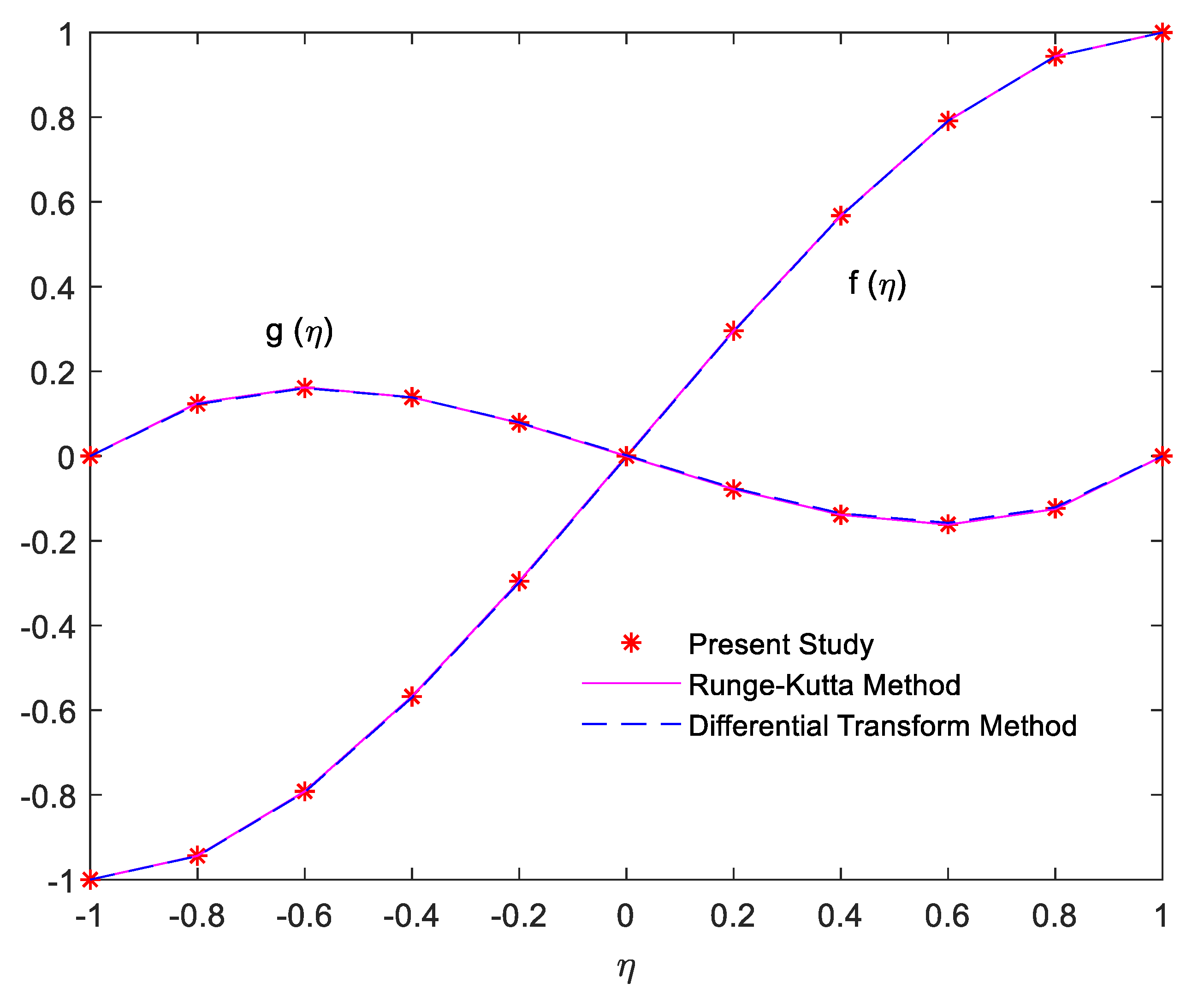
This section is committed to exploring the numerical outcomes with the support of physical interpretations. The flow and heat transport attributes through a permeable channel are characterized using micropolar fluid. A struggle is made to check out the impacts of pertinent parameters on the flow velocities f ( η ) & f ( η ) , microrotation g ( η ) , and temperature θ ( η ) as well as on shear stresses, couple stresses, and rate of heat transportation. The step sizes as well as the edges (for boundary layers) are balanced such that the flow, microrotation, and temperature profiles demonstrate an asymptotic behavior. We have taken fixed values of the parameter in the simulation (computational) analysis such as Re = 1 , C 1 = 0.1 , C 2 = 0.2 , C 3 = 0.3 , M = 1 , A = 0.5 , Pr = 6.2 , and Ec = 0.2 otherwise identified. An excellent comparison of our numerical results (please see Table 1) with the literature for the classical Newtonian fluid is a source of validation for our computational technique. In order to validate our mathematical model and the computational scheme for non-Newtonian fluid, our numerical results for f η and g η against the fixed values C 1 = 0.1 ,   C 2 = 1 , C 3 = 0.1 ,   M = 0 ,   A = 0 and Re = 0.1 of the governing parameters, for the liming case, have been plotted (please see Figure 2.) against the ones reported in literature (Mirzaaghaian and Ganji [41]), by employing the Runge–Kutta method and the Differential Transform method. Excellent comparison confirms the correctness of the micropolar model and the accuracy of our numerical approach.
The simulation values of the material constants are given in Table 2. The numerical consequences for several steps of η are enumerated in Table 3. This table specifies that our numerical results converge in the best way with the values of step-size η , and it confirms the accuracy of our numerical procedure. Table 4 reveals that the Reynolds number generates an opposite effect on the lower as well as an upper wall for shear and couple stresses. Its effect substantially reduces the couple and shear stresses on the lower wall y = c and increases on the upper wall y = c , whereas the heat transfer rate increases on both walls with its effect. The values of shear stresses, heat transport rates, and couple stresses on both channel walls for distinct values of the magnetic field are portrayed in Table 5. All values of f ( ± 1 ) and θ ( ± 1 ) seem to be increasing on both walls with the impact of M . The couple stress enhances for g ( 1 ) and reduces for g ( 1 ) . In view of mechanics, the magnetic field applies a frictional force, known as the Lorentz force. Due to this force, fluid is dragged towards the walls. This anomaly not only increases shear stresses at the walls but also tends to rotate microfluid particles rapidly. Moreover, the Lorentz force produces the temperature difference (between the temperature at channel walls and temperature of fluid) and hence increases the heat transport at both walls.
Table 6 reveals the influence of permeability parameter A on heat transfer rate, couple, and shear stress for fixed values of M ,   Pr ,   Ec ,   Re , and material constants C 1 , C 2 and C 3 . All of the physical quantities enhance on upper as well as lower channel walls with the effect of A . The analysis of skin frictions, couple stresses, and rates of heat transfer for material parameters on both the channel walls is provided in Table 7. The diverse values of micropolar material constants are given in Table 2. The first case (see Table 2) where all values of material parameters are taken as zero represents the Newtonian case, whereas the remaining values are randomly chosen to determine their impacts on the flow [54,55]. The combined impact of C 1 , C 2 and C 3 is to devaluate the skin friction and enhance the couple stresses, whereas the joint effect of these parameters causes a reduction in the heat transport rate on the lower wall and escalation on the upper permeable wall.
The rates of heat transfer for diverse  E c and Pr values recorded in Table 8 and Table 9 portray that the Eckert number upsurges the heat transport rate on both walls; however, the Prandtl number causes a decrease in θ ( 1 ) and an increase in θ ( 1 ) . This study leads to the results that the heat transportation rates, shear, and couple stresses may be accommodated by selecting suitable parametric values and the permeability on both walls to achieve the desired consequences.
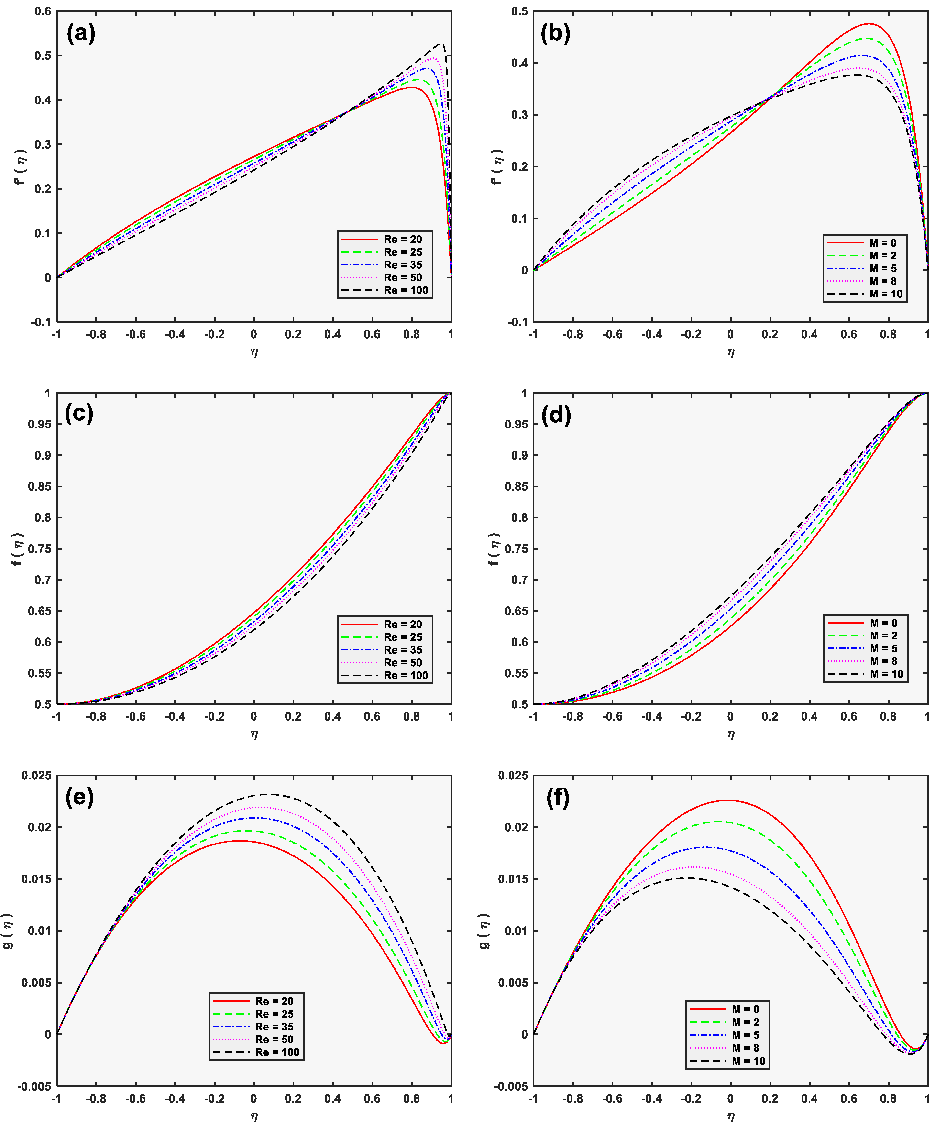
The streamwise velocity f , the angular velocity g , and the normal velocity f are depicted in Figure 3 for the assigned values of M and R e . The velocity f initially decreases and then increases gradually for R e when concavity changes, but, contrarily, the velocity f initially increases and then decreases gradually for M when concavity changes (see Figure 3a,b). It can be seen from Figure 3c,d that the effect of the Reynolds number is to downturn the normal velocity, but the magnetic field parameter enhances the normal velocity. In the same way, the angular velocity is increased by the Reynolds number and decreased by the magnetic field parameter (as depicted in Figure 3e,f). It is worth mentioning here that the value of a magnetic parameter is fixed (e.g., M = 10 ) in Figure 3a,c,e. Similarly, the value of Reynolds number is fixed (e.g., Re = 10 ) in Figure 3b,d,f. It is observed here that both the magnetic parameter and the Reynolds number yield opposite effects on the profiles of streamwise, angular, and normal velocities. The retarding force elevates with amplifying values of magnetic field parameters. Consequently, the magnetic field suppresses the streamwise velocity (after a change in concavity) and improves the heat transport rate.
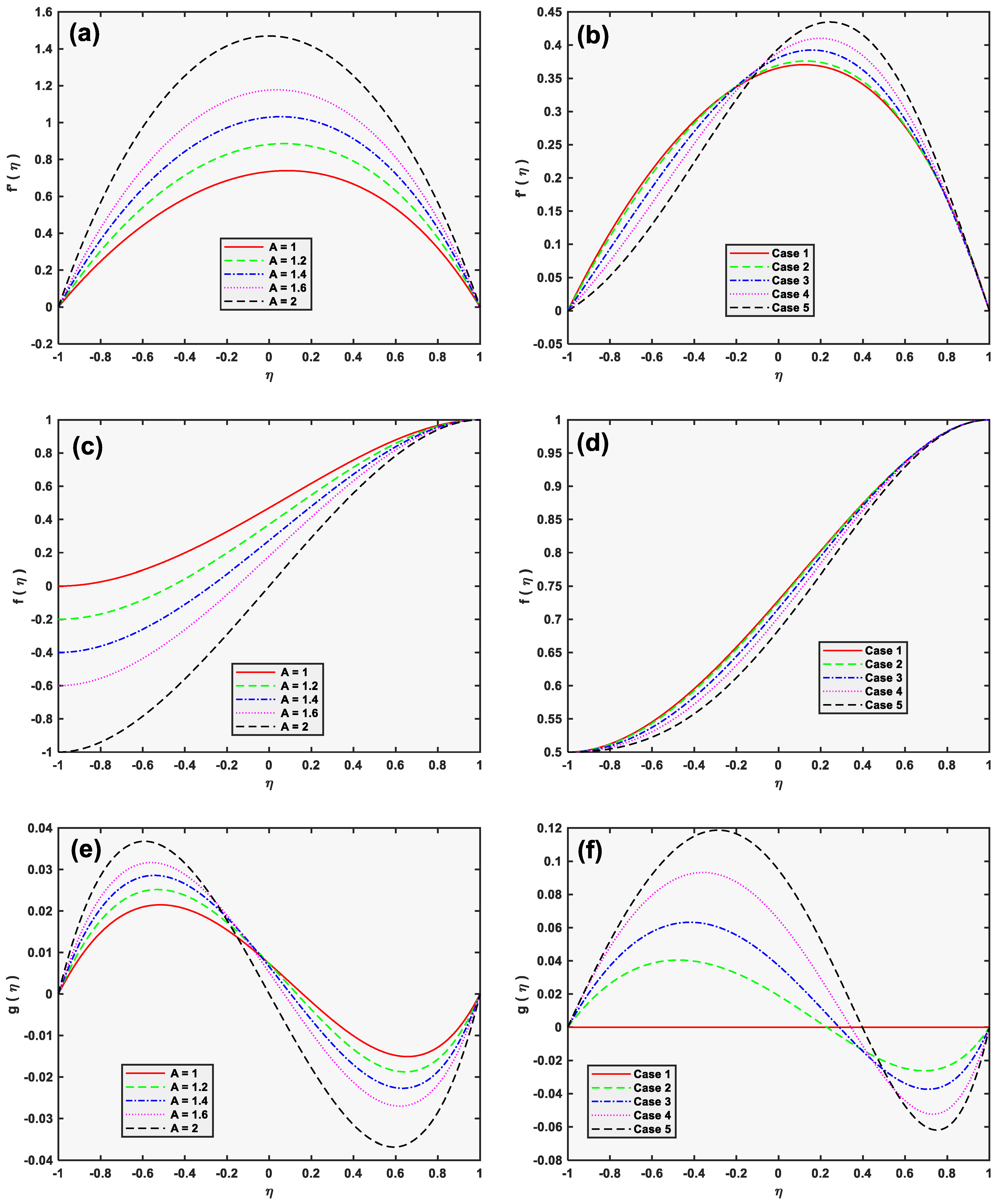
The effect of A (permeability parameter) on non-dimensional velocities is elucidated in Figure 4a,c,e. The streamwise velocity and the microrotation increase, whereas the normal velocity reduces with an increase in the permeability parameter.
The same velocities ( f , f and g ) are displayed in Figure 4b,d,f for various guesses of micropolar material parameters C 1 , C 2 & C 3 (see values in Table 2). The numerical results designate that the normal velocity is depressed while streamwise velocity (after concavity) and microrotation increase by escalating the material parameters. Velocity f tends to decrease at the start, but, after concavity, it attains maximum value near the upper wall of the channel (Figure 4b). It may be attributed because the permeability drives streamwise moving fluid beyond the wall and causes an increase in the velocity near the upper wall. The microrotation profile for micropolar parameters is concave upward in the upper half of the channel and concave downward in the lower half of the channel. When C 1 = C 2 = C 3 = 0 at both permeable walls, the effect of skin frictions equally spreads from the walls such that the angular velocity (microrotation) is zero at the center of the channel (see Figure 4f). The skin friction tends to rotate the micropolar fluid in opposite routes on the walls. This is why the microrotation has opposite signs near the lower channel wall.
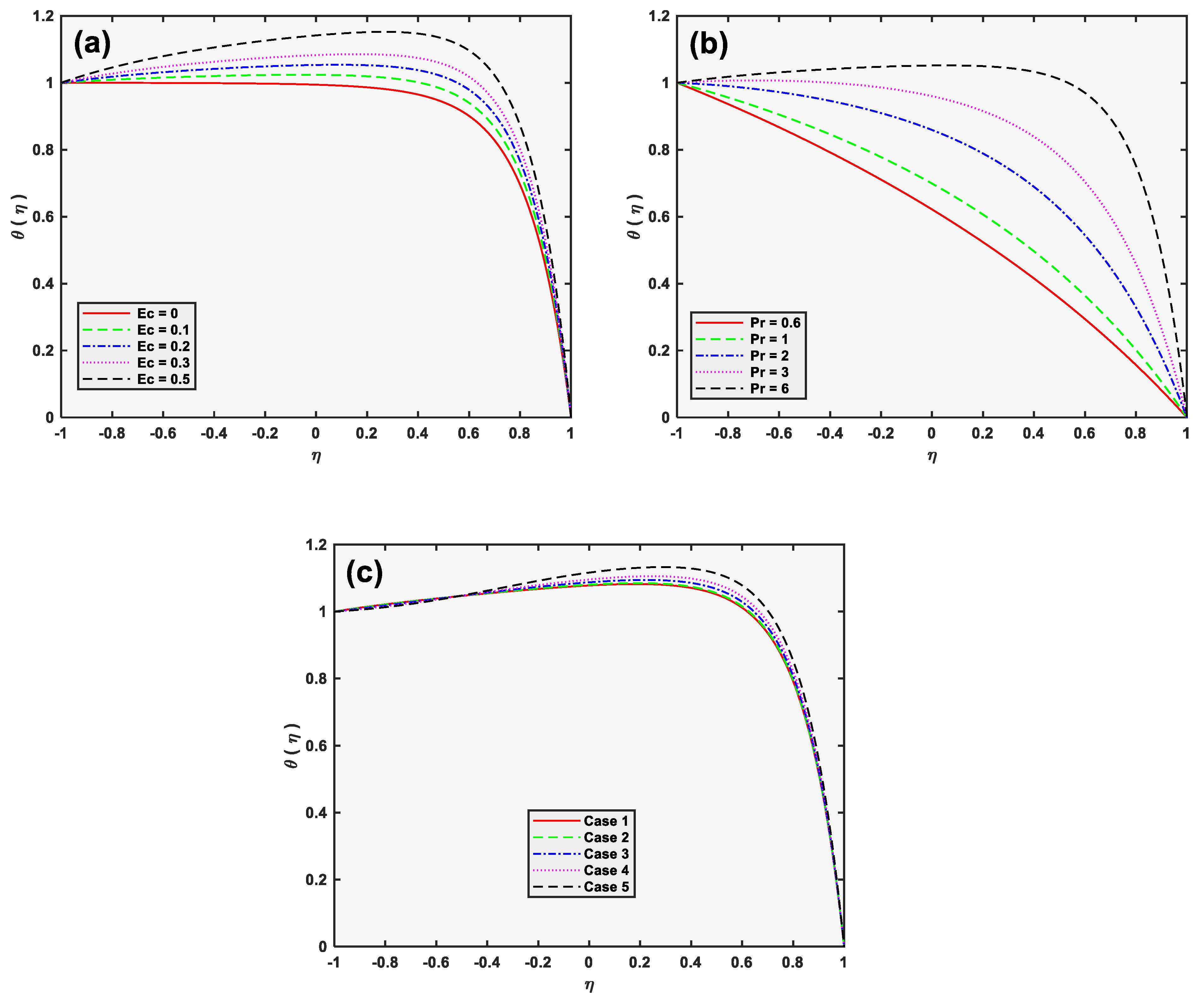
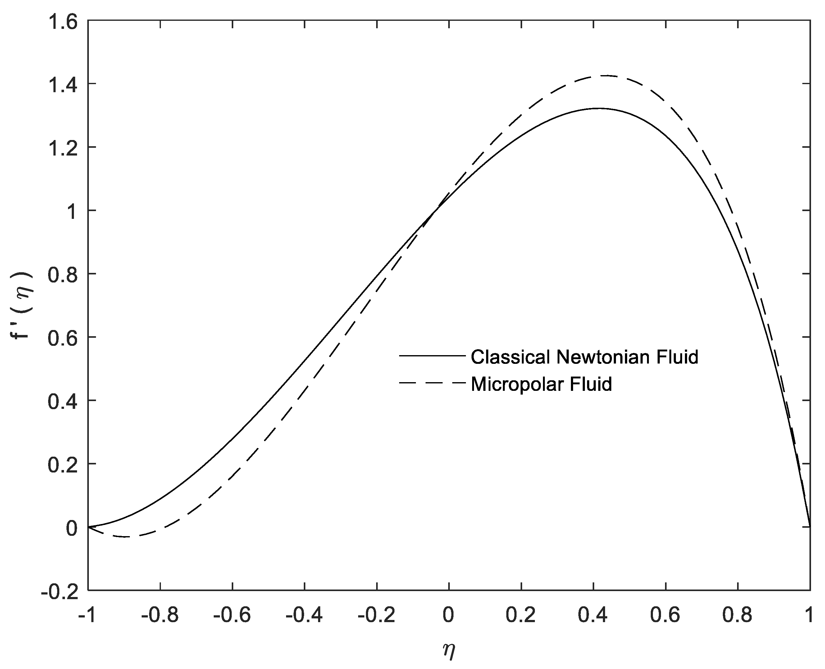
Temperature θ ( η ) is depicted in Figure 5a,b for multiple values of E c (Eckert number) and Pr (Prandtl number) as a function of the coordinate η . For both of these parameters, temperature enhances near the upper wall of the channel. The results of Figure 5c expresses that the temperature profile θ accelerates with an increment in the material parameters, while Figure 6 shows the velocity distribution across the channel for Newtonian and micropolar fluids.

6. Conclusions

An inclusive computational analysis of a micropolar flow with an allowance for heat transfer through a channel is presented. The effects of magnetohydrodynamics (MHD) and viscous dissipation have also been taken in the flow. The quasi-linearization is utilized to attain the solution against microrotation, velocity, and thermal energy. The key points of the present work may be mentioned as:
  • The permeability parameter and the material parameters tend to enhance the microrotation, but these parameters depreciate the normal velocities.
  • The Reynolds number inserts a low effect on couple stresses while it yields a significant effect on skin friction and heat transport rates.
  • The permeability parameter A substantially enhances shear stresses, couple stresses, and the rates of heat transfer on both the channel walls.
  • The impact of the Eckert and the Prandtl number is to uplift the temperature curves.
  • The micropolar constants C 1 , C 2 & C 3 intensively affect the microrotation rather than the streamwise and the normal velocities.
  • The micropolar fluid causes an escalation in couple stresses and a reduction in the shear stresses.

Author Contributions

Conceptualization, J.C., K.A. and S.A. (Shabbir Ahmad); methodology, K.A.; software, K.A.; S.A. (Shabbir Ahmad) validation; S.A. (Shabbir Ahmad), K.A. and S.A. (Sohail Ahmad); formal analysis, S.A. (Sohail Ahmad); investigation, S.A. (Shabbir Ahmad); resources, J.C., S.A. (Sohail Ahmad); data curation, S.A. (Shabbir Ahmad); writing—original draft preparation, S.A. (Shabbir Ahmad); writing—review and editing, J.C., S.A. (Sohail Ahmad); visualization, J.C.; supervision, K.A., J.C.; project administration, J.C.; funding acquisition, J.C.; All authors have read and agreed to the published version of the manuscript.

Funding

This research was funded by National Natural Science Foundation of China grant number 51874262, and the Fundamental Research Funds for the Central Universities (China University of Geosciences, Wuhan) grant number CUGGC04.

Data Availability Statement

Data will be provided by the authors on request.

Acknowledgments

The authors wish to express their sincere thanks to the China Scholarship Council (CSC) for the financial support to accomplish this research and honourable reviewers and the editor.

Conflicts of Interest

We declare that we have no conflict of interest.

References

  1. Vogel, W.; Patterson, A. An Experimental Investigation of Additives Injected into the Boundary Layer of an Underwater Body; Pacific Naval Laboratory of the Defense Research Board of Canada Report: Toronto, ON, Canada, 1964; p. 64-2. [Google Scholar]
  2. Fabula, A.; Hoyt, J. The Effect of Additives on Fluid Friction; National Technical Information Service: Columbus, OH, USA, 1964. [Google Scholar]
  3. Eringen, A.C. Theory of micropolar fluids. J. Math. Mech. 1966, 16, 1–18. [Google Scholar] [CrossRef]
  4. Eringen, A.C. Theory of thermomicrofluids. J. Math. Anal. Appl. 1972, 38, 480–496. [Google Scholar] [CrossRef] [Green Version]
  5. Ariman, T.; Turk, M.; Sylvester, N. Microcontinuum fluid mechanics—A review. Int. J. Eng. Sci. 1973, 11, 905–930. [Google Scholar] [CrossRef]
  6. Ariman, T.; Turk, M.; Sylvester, N. Applications of microcontinuum fluid mechanics. Int. J. Eng. Sci. 1974, 12, 273–293. [Google Scholar] [CrossRef]
  7. Brody, J.P.; Yager, P. Low Reynolds number micro-fluidic devices. In Proceedings of the Solid-State Sensor and Actuator Workshop, Washington, DC, USA, 2 June 1996; pp. 105–108. [Google Scholar]
  8. Holmes, D.; Vermeulen, J. Velocity profiles in ducts with rectangular cross sections. Chem. Eng. Sci. 1968, 23, 717–722. [Google Scholar] [CrossRef]
  9. Lee, J.; Wang, X.; Chen, J. An Overview of Micromorphic Theory in Multiscaling of Synthetic and Natural Systems with Self-Adaptive Capability; National Taiwan University of Science and Technology Press: Taipei, Taiwan, 2010; p. 81-4. [Google Scholar]
  10. Eringen, A.C. Simple microfluids. Int. J. Eng. Sci. 1964, 2, 205–217. [Google Scholar] [CrossRef]
  11. Eringen, A.C. Microcontinuum Field Theories: I. Foundations and Solids; Springer Science & Business Media: Berlin/Heidelberg, Germany, 2012. [Google Scholar]
  12. Eringen, A. Microcontinuum Field Theories. II: Fluent Media; Springer: New York, NY, USA, 2001. [Google Scholar]
  13. Papautsky, I.; Brazzle, J.; Ameel, T.; Frazier, A.B. Laminar fluid behavior in microchannels using micropolar fluid theory. Sens. Actuators A Phys. 1999, 73, 101–108. [Google Scholar] [CrossRef]
  14. Souayeh, B.; Alfannakh, H. Radiative melting heat transfer through a micropolar nanoliquid by using Koo and Kleinstreuer model. Eur. Phys. J. Plus 2021, 136, 1–15. [Google Scholar] [CrossRef]
  15. Tassaddiq, A. Impact of Cattaneo-Christov heat flux model on MHD hybrid nano-micropolar fluid flow and heat transfer with viscous and joule dissipation effects. Sci. Rep. 2021, 11, 1–14. [Google Scholar] [CrossRef] [PubMed]
  16. Jaiswal, S.; Yadav, P.K. A micropolar-Newtonian blood flow model through a porous layered artery in the presence of a magnetic field. Phys. Fluids 2019, 31, 071901. [Google Scholar] [CrossRef]
  17. Wang, Z.; Li, H.; Lan, X.; Wang, K.; Yang, Y.; Lisitsa, V. Formation damage mechanism of a sandstone reservoir based on micro-computed tomography. Adv. Geo-Energy Res. 2021, 5, 25–38. [Google Scholar] [CrossRef]
  18. Ahmad, S.; Ashraf, M.; Ali, K. Simulation of thermal radiation in a micropolar fluid flow through a porous medium between channel walls. J. Therm. Anal. Calorim. 2020, 144, 941–953. [Google Scholar] [CrossRef]
  19. Lund, L.A.; Omar, Z.; Khan, I.; Kadry, S.; Rho, S.; Mari, I.A.; Nisar, K.S. Effect of viscous dissipation in heat transfer of MHD flow of micropolar fluid partial slip conditions: Dual solutions and stability analysis. Energies 2019, 12, 4617. [Google Scholar] [CrossRef] [Green Version]
  20. Khader, M.; Sharma, R.P. Evaluating the unsteady MHD micropolar fluid flow past stretching/shirking sheet with heat source and thermal radiation: Implementing fourth order predictor–corrector FDM. Math. Comput. Simul. 2021, 181, 333–350. [Google Scholar] [CrossRef]
  21. Tlili, I.; Ramzan, M.; Nisa, H.U.; Shutaywi, M.; Shah, Z.; Kumam, P. Onset of gyrotactic microorganisms in MHD Micropolar nanofluid flow with partial slip and double stratification. J. King Saud Univ. Sci. 2020, 32, 2741–2751. [Google Scholar] [CrossRef]
  22. Gangadhar, K.; Narayana, K.L.; Kumar, P.S.; Kumar, B.R. MHD micropolar fluid flow over a stretching permeable sheet in the presence of thermal radiation and thermal slip flow: A numerical study. In Proceedings of the IOP Conference Series: Materials Science and Engineering, Ongole, India, 1 November 2017; p. 062010. [Google Scholar]
  23. Sui, J.; Zhao, P.; Cheng, Z.; Zheng, L.; Zhang, X. A novel investigation of a micropolar fluid characterized by nonlinear constitutive diffusion model in boundary layer flow and heat transfer. Phys. Fluids 2017, 29, 023105. [Google Scholar] [CrossRef] [PubMed] [Green Version]
  24. Alizadeh-Haghighi, E.; Jafarmadar, S.; Arya, S.K.; Rezazadeh, G. Study of micropolar fluid flow inside a magnetohydrodynamic micropump. J. Braz. Soc. Mech. Sci. Eng. 2017, 39, 4955–4963. [Google Scholar] [CrossRef]
  25. Maleki, M.A.; Soltani, M.; Kashaninejad, N.; Nguyen, N.-T. Effects of magnetic nanoparticles on mixing in droplet-based microfluidics. Phys. Fluids 2019, 31, 032001. [Google Scholar] [CrossRef] [Green Version]
  26. Ali, K.; Ashraf, M.; Jameel, N. Numerical simulation of magnetohydrodynamic micropolar fluid flow and heat transfer in a channel with shrinking walls. Can. J. Phys. 2014, 92, 987–996. [Google Scholar] [CrossRef]
  27. Ahmad, S.; Ashraf, M.; Ali, K. Micropolar Fluid Flow with Heat Generation through a Porous Medium. Punjab Univ. J. Math. 2020, 52, 101–113. [Google Scholar]
  28. Srinivasacharya, D.; Bindu, K.H. Entropy generation in a micropolar fluid flow through an inclined channel. Alex. Eng. J. 2016, 55, 973–982. [Google Scholar] [CrossRef] [Green Version]
  29. Boukrouche, M.; Paoli, L.; Ziane, F. Micropolar fluid flow in a thick domain with multiscale oscillating roughness and friction boundary conditions. J. Math. Anal. Appl. 2021, 495, 124688. [Google Scholar] [CrossRef]
  30. Ahmed, R.; Ali, N.; Khan, S.U.; Rashad, A.; Nabwey, H.A.; Tlili, I. Novel microstructural features on heat and mass transfer in peristaltic flow through a curved channel. Front. Phys. 2020, 8, 178. [Google Scholar] [CrossRef]
  31. Ding, Z.; Jian, Y.; Wang, L.; Yang, L. Analytical investigation of electrokinetic effects of micropolar fluids in nanofluidic channels. Phys. Fluids 2017, 29, 082008. [Google Scholar] [CrossRef]
  32. Singh, K.; Pandey, A.K.; Kumar, M. Entropy Generation Impact on Flow of Micropolar Fluid via an Inclined Channel with Non-Uniform Heat Source and Variable Fluid Properties. Int. J. Appl. Comput. Math. 2020, 6, 1–12. [Google Scholar] [CrossRef]
  33. Ahmad, S.; Ashraf, M.; Ali, K. Numerical simulation of viscous dissipation in a micropolar fluid flow through a porous medium. J. Appl. Mech. Tech. Phys. 2019, 60, 996–1004. [Google Scholar] [CrossRef]
  34. Fonseca, W.d.S.; Araújo, R.C.; Cruz, D.O.d.A. Analysis of the magnetohydrodynamic behavior of the fully developed flow of conducting fluid. Energies 2021, 14, 2463. [Google Scholar] [CrossRef]
  35. Ali, A.; Umar, M.; Bukhari, Z.; Abbas, Z. Pulsating flow of a micropolar-Casson fluid through a constricted channel influenced by a magnetic field and Darcian porous medium: A numerical study. Results Phys. 2020, 19, 103544. [Google Scholar] [CrossRef]
  36. Sheikholeslami, M.; Rokni, H.B. Magnetic nanofluid flow and convective heat transfer in a porous cavity considering Brownian motion effects. Phys. Fluids 2018, 30, 012003. [Google Scholar] [CrossRef]
  37. Asha, S.; Deepa, C. Entropy generation for peristaltic blood flow of a magneto-micropolar fluid with thermal radiation in a tapered asymmetric channel. Results Eng. 2019, 3, 100024. [Google Scholar] [CrossRef]
  38. Tetbirt, A.; Bouaziz, M.; Abbes, M.T. Numerical study of magnetic effect on the velocity distribution field in a macro/micro-scale of a micropolar and viscous fluid in vertical channel. J. Mol. Liq. 2016, 216, 103–110. [Google Scholar] [CrossRef]
  39. Umar, M.; Ali, A.; Bukhari, Z.; Shahzadi, G.; Saleem, A. Impact of Lorentz force in thermally developed pulsatile micropolar fluid flow in a constricted channel. Energies 2021, 14, 2173. [Google Scholar] [CrossRef]
  40. Ahmad, S.; Cai, J.; Ali, K. Prediction of new vortices in single-phase nanofluid due to dipole interaction. J. Therm. Anal. Calorim. 2020, 1–15. [Google Scholar] [CrossRef]
  41. Mirzaaghaian, A.; Ganji, D. Application of differential transformation method in micropolar fluid flow and heat transfer through permeable walls. Alex. Eng. J. 2016, 55, 2183–2191. [Google Scholar] [CrossRef] [Green Version]
  42. Singh, K.; Kumar, M. Influence of chemical reaction on heat and mass transfer flow of a micropolar fluid over a permeable channel with radiation and heat generation. J. Thermodyn. 2016. [Google Scholar] [CrossRef] [Green Version]
  43. Mahian, O.; Mahmud, S.; Pop, I. Analysis of first and second laws of thermodynamics between two isothermal cylinders with relative rotation in the presence of MHD flow. Int. J. Heat Mass Transf. 2012, 55, 4808–4816. [Google Scholar] [CrossRef]
  44. Cai, J.; Hu, X.; Xiao, B.; Zhou, Y.; Wei, W. Recent developments on fractal-based approaches to nanofluids and nanoparticle aggregation. Int. J. Heat Mass Transf. 2017, 105, 623–637. [Google Scholar] [CrossRef] [Green Version]
  45. Mahian, O.; Javidmehr, M.; Kasaeian, A.; Mohasseb, S.; Panahi, M. Optimal sizing and performance assessment of a hybrid combined heat and power system with energy storage for residential buildings. Energy Convers. Manag. 2020, 211, 112751. [Google Scholar] [CrossRef]
  46. Zhang, X.; Zikanov, O. Convection instability in a downward flow in a vertical duct with strong transverse magnetic field. Phys. Fluids 2018, 30, 117101. [Google Scholar] [CrossRef] [Green Version]
  47. Ahmad, S.; Ali, K.; Rizwan, M.; Ashraf, M. Heat and mass transfer attributes of copper–aluminum oxide hybrid nanoparticles flow through a porous medium. Case Stud. Therm. Eng. 2021, 25, 100932. [Google Scholar] [CrossRef]
  48. Ahmad, S.; Ali, K.; Ashraf, M. MHD flow of Cu-Al2O3/water hybrid nanofluid through a porous media. J. Porous Media 2021, 24, 61–73. [Google Scholar] [CrossRef]
  49. Berman, A.S. Laminar flow in channels with porous walls. J. Appl. Phys. 1953, 24, 1232–1235. [Google Scholar] [CrossRef]
  50. Ahraf, M.; Kamal, M.; Syed, K. Numerical simulation of a micropolar fluid between a porous disc and a non-porous disk. J. Appl. Math. Modeling 2009, 33, 1933–1943. [Google Scholar] [CrossRef]
  51. Ashraf, M.; Kamal, M.A.; Syed, K. Numerical study of asymmetric laminar flow of micropolar fluids in a porous channel. Comput. Fluids 2009, 38, 1895–1902. [Google Scholar] [CrossRef]
  52. Ahmad, S.; Ashraf, M.; Ali, K. Bioconvection due to gyrotactic microbes in a nanofluid flow through a porous medium. Heliyon 2020, 6, e05832. [Google Scholar] [CrossRef]
  53. Shrestha, G.; Terrill, R. Laminar flow with large injection through parallel and uniformly porous walls of different permearility. Q. J. Mech. Appl. Math. 1968, 21, 413–432. [Google Scholar] [CrossRef]
  54. Ashraf, M.; Batool, K. MHD flow and heat transfer of a micropolar fluid over a stretchable disk. J. Theor. Appl. Mech. 2013, 51, 25–38. [Google Scholar]
  55. Ashraf, M.; Syed, K.; Anwar Kamal, M. Numerical simulation of flow of micropolar fluids in a channel with a porous wall. Int. J. Numer. Methods Fluids 2011, 66, 906–918. [Google Scholar] [CrossRef]
Figure 1. Porous channel model.
Energies 14 04286 g001
Figure 2. Comparison of our numerical results with literature, for f η and g η for C 1 = 0.1 ,   C 2 = 1 ,   C 3 = 0.1 ,   M = 0 , A = 0 , and Re = 0.1 .
Energies 14 04286 g002
Figure 3. Impact of the Reynolds number Re and the magnetic parameter M on different profiles (a) Streamwise velocity with different Re ; (b) Streamwise velocity with different M ; (c) Normal velocity with different Re ; (d) Normal velocity with different M ; (e) Microrotation with different Re ; (f) Microrotation with different M .
Energies 14 04286 g003
Figure 4. Impact of the permeability parameter A and the micropolar parameters C 1 ,   C 2 ,   C 3 on different profiles (a) Streamwise velocity with different A ; (b) Streamwise velocity with various cases; (c) Normal velocity with different A ; (d) Normal velocity with various cases; (e) Microrotation with different A ; (f) Microrotation with various cases.
Energies 14 04286 g004
Figure 5. Impact of different parameters on temperature profile (a) Eckert number; (b) Prandtl number; (c) Various cases of Micropolar parameter.
Energies 14 04286 g005
Figure 6. Velocity distribution across the channel for Newtonian and micropolar fluids for R e = 5 , M = 0 ,   A = 1.5 ,   C 1 = 0.1 ,   C 2 = 1 , and C 3 = 0.1 .
Energies 14 04286 g006
Table 1. Comparison of our results with the literature for the classical Newtonian fluid proposed by Shrestha and Terrill [53].
Re A F 0
(Our Results)
F 0
(Literature)
F 1
(Our Results)
F 1
(Literature)
−149.131.92789.9953429.994 −9.274998−9.274
−74.721.930510.09908910.098−9.402380−9.402
−48.541.946110.19862110.197−9.658360−9.657
−16.161.976610.66225510.660−10.443826−10.440
−156.441.862210.03445210.035 −8.654121−8.635
Table 2. Non-dimensional parameters C 1 , C 2 , and C 3 for different cases.
C a s e s C 1 C 2 C 3
1 (Newtonian)0.00.00.0
20.50.80.6
31.51.21.0
42.01.81.5
52.52.21.8
Table 3. Heat transfer rate for different grids levels.
θ η
η 1 st   g r i d   h = 0.04 2 nd   g r i d   h = 0.02 3 rd   g r i d   h = 0.01
−101.110 × 10−142.220 × 10⁻¹⁴
−0.80.1148370.1148750.114884
−0.60.2097930.2098010.209803
−0.40.2844900.2844780.284474
−0.20.3377570.3377340.337728
00.3675010.3674800.367475
0.20.3705970.3705920.370591
0.40.3426640.3426900.342697
0.60.2776590.2777390.277759
0.80.1672260.1673840.167424
Table 4. Shear stresses, couple stresses, and heat transfer rate for different R e .
R e f ( 1 ) f ( 1 ) g ( 1 ) g ( 1 ) θ ( 1 ) θ ( 1 )
200.232365−9.5556300.0437480.0538470.001080−1.091 × 10²
250.228974−11.6633290.0436570.0539948.3896 × 10−4−1.293 × 10²
350.225328−15.5227210.0435580.0541605.802 × 10−4−1.628 × 10²
500.222740−20.5660320.0434880.0542813.969 × 10−4−2.008 × 10²
1000.219890−32.9746210.0434100.0544161.933 × 10−4−2.717 × 10²
Table 5. Shear stresses, couple stresses, and heat transfer rate for different M .
M f ( 1 ) f ( 1 ) g ( 1 ) g ( 1 ) θ ( 1 ) θ ( 1 )
00.580726−0.9700720.0479340.0496480.088538−6.553525
20.659488−1.0138880.0481190.0495860.120434−7.031084
50.762826−1.0812150.0483260.04953010.170245−7.729011
80.853300−1.1474120.0484780.0494990.221727−8.410174
100.908217−1.1902060.0485600.0494870.256740−8.856996
Table 6. Shear stresses, couple stresses, and heat transfer rate for different A .
A f ( 1 ) f ( 1 ) g ( 1 ) g ( 1 ) θ ( 1 ) θ ( 1 )
11.338391−1.8603580.0973100.0992331.027413−9.996802
1.21.659443−2.1720140.1173280.1190942.403682−13.10309
1.42.003807−2.4627210.1374990.1389695.734645−18.68517
1.62.374332−2.7321990.1578030.15886213.80296−28.85614
23.206550−3.2065500.1987240.19872464.49000−70.19019
Table 7. Shear stresses, couple stresses, and heat transfer rate for different cases.
C a s e s f ( 1 ) f ( 1 ) g ( 1 ) g ( 1 ) θ ( 1 ) θ ( 1 )
10.636754−0.989152000.106991−6.770115
20.590481−0.9656420.1705400.1950500.100538−6.785268
30.458533−0.9190760.2268820.2930290.082804−6.839315
40.335757−0.9069240.2805790.4442660.067329−6.908943
50.196319−0.9305650.2790390.5592870.052486−7.024112
Table 8. Heat transfer rate for different E c .
E c θ ( 1 ) θ ( 1 )
0−6.407 × 10⁻⁴−6.053392
0.10.051843−6.423560
0.20.104327−6.793728
0.30.156812−7.163896
0.50.261780−7.904233
Table 9. Heat transfer rate for different Pr .
Pr θ ( 1 ) θ ( 1 )
0.6−0.304826−0.841981
1−0.201856−1.129528
2−0.032221−2.029494
30.046912−3.099861
50.095148−5.401683
Publisher’s Note: MDPI stays neutral with regard to jurisdictional claims in published maps and institutional affiliations.