Article

Numerical Study of Heat Transfer Intensification in a Circular Tube Using a Thin, Radiation-Absorbing Insert. Part 1: Thermo-Hydraulic Characteristics

by
Piotr Bogusław Jasiński
Institute of Turbomachinery, Lodz University of Technology, 90-924 Lodz, Poland
Energies 2021, 14(15), 4596; https://doi.org/10.3390/en14154596
Submission received: 15 June 2021 / Revised: 20 July 2021 / Accepted: 21 July 2021 / Published: 29 July 2021
(This article belongs to the Special Issue Computational Heat Transfer and Fluid Mechanics)

Abstract

:
The presented paper, which is the first of two parts, shows the results of numerical investigations of a heat exchanger channel in the form of a cylindrical tube with a thin insert. The insert, placed concentrically in the pipe, uses the phenomenon of thermal radiation absorption to intensify the heat transfer between the pipe wall and the gas. Eight geometric configurations of the insert size were numerically investigated using CFD software, varying its diameter from 20% to 90% of the pipe diameter and obtaining the thermal-flow characteristics for each case. The tests were conducted for a range of numbers Re = 5000–100,000 and a constant temperature difference between the channel wall and the average gas temperature of ∆T = 100 °C. The results show that the highest increase in the Nu number was observed for the inserts with diameters of 0.3 and 0.4 of the channel diameter, while the highest flow resistance was noted for the inserts with diameters of 0.6–0.7 of the channel diameter. The f/fs(Re) and Nu/Nus(Re) ratios are shown on graphs indicating how much the flow resistance and heat transfer increased compared to the pipe without an insert. Two methods of calculating the Nu number are also presented and analysed. In the first one, the average fluid temperature of the entire pipe volume was used to calculate the Nu number, and in the second, only the average fluid temperature of the annular portion formed by the insert was used. The second one gives much larger Nu/Nus ratio values, reaching up to 8–9 for small Re numbers.

1. Introduction

There are many ways to intensify the heat transfer in heat exchanger channels, e.g., by using ribs of different shapes or special tabs on the inner wall [1,2,3]. They aim to increase the fluid’s turbulence in the laminar boundary layer and increase the heat transfer surface. Another, also quite a popular method to improve heat transfer is to disturb the flow in the whole pipe cross-section, which can be achieved by, e.g., introducing special disturbing inserts, twisted tapes, or wire coils into the duct. A common feature of this type of turbulisers, regardless of their shapes, is the strong influence of some geometrical parameters on the heat-flow characteristics (e.g., the rib angle, its height or thickness) [4,5,6,7,8]. However, any such turbuliser, in addition to a local increase in heat transfer intensity, simultaneously causes a significant increase in flow resistance, which involves an obvious power increase to pump the working fluid.
This paper presents testing channels with an insert that does not turbulise the flow as most such elements do, but instead uses an additional heat transport mechanism, thermal radiation. Obviously, due to the necessary radiation transmittance of the working fluid, it is only applicable to gases.
The insert presented in this article is made in the form of a thin, smooth pipe and placed parallel and concentrically to the exchanger channel’s walls (Figure 1). Apart from the standard, convective method of heat transport between the wall and the fluid, the heat transfer intensification mechanism additionally uses the phenomenon of thermal radiation between the pipe wall and the insert. During the fully developed fluid flow, the insert placed in the centre of the tube does not mix the fluid and has a different temperature than the wall. Due to the temperature difference, heat is transferred by radiation between the wall surface and the insert. Assuming that the working gas is completely transparent and does not absorb radiation, the total radiant heat flux is transferred to the insert, increasing its temperature and becoming an additional heat transfer surface while transferring heat to the fluid on both sides by convection.
Unfortunately, no papers describe this type of insert in the available literature, making it impossible to refer directly to the presented research. Therefore, the articles that describe the most similar cases using turbulence inserts and with radiation heat transfer were analysed.
There is quite a lot of research on solar collectors in the literature, where the phenomena of radiation and convection occur together. In such a collector, solar radiation penetrates through a transparent glass tube and, by heating the absorber, will transfer heat to the fluid by convection. However, it is only in the absorber (inside the channel) that the heat transfer is intensified by placing various inserts that turbulise the flow [9,10,11].
The intensification of the heat transfer in the channel, resulting from the turbulence of the fluid through various methods, has been analysed by many researchers. The variable value was often some geometrical feature of the insert, influencing the flow resistance and heat transfer. For example, Eiamsa-ard and Promvonge [12] studied diamond-shaped turbulence inserts with their ends touching each other. The variable parameters were the length of a single element and the angle of inclination of the diamond face. The highest Nu numbers were observed for the shortest elements and those with the highest inclination angles. Kongkaitpaiboon et al. [13] experimented with an insert consisting of round rings attached to a pipe wall. He analysed two geometric variables: the rings’ inner diameters and the distance between them (three diameters and three longitudinal distances) in a small range of Reynolds numbers (4000–20,000). The study showed that the best heat transfer occurred with the ring’s smallest inner diameter and the smallest distances between the rings. Durums [14], on the other hand, in their study, presents the influence of the conical nozzle angle on the pressure drop and heat transfer intensity. The presented results show that as the turbuliser nozzle angle increases, the Nusselt number and friction coefficient also increase nonlinearly. In papers [15,16,17], Jasiński presented a comprehensive experimental and numerical study of a ball insert, with varying ball diameters and longitudinal distances between them, at a fairly large range of Re numbers 5000–300,000. It turned out that the largest coefficient of thermal efficiency was obtained by the inserts with the smallest diameter and largest longitudinal distance, and additionally, at large Re numbers. One example of twisted tape inserts research was presented in [18] by Bas and Ozceyhan. The highest efficiencies were obtained for the smallest Re numbers 5000–10,000 with a small gap between the pipe wall and the insert for all the insert geometries they studied.
This work’s originality is based on the use of an additional heat transport mechanism, which is radiation from the pipe wall to the absorption insert. The presented results were obtained for a relatively small temperature difference ∆T = 100 °C, as is standard for radiation processes. Further work will focus on research for developing such inserts at greater temperature differences to improve the thermal efficiency of various devices, such as solar air ducts, heaters, and heat exchangers. The concept of this type of insert may be of great importance, especially for high-temperature combustion and heat recovery processes, where thermal radiation is the dominant method of heat transfer.

2. Geometry of Insert and Principle of Operation

The principle of operation of such an insert is based on the fact that the total heat flux supplied to the outer wall of the channel is partially transferred by convection to the fluid, and at the same time, a part of this flux is transferred to the insert by radiation, Figure 1. Because the insert does not cause turbulence and mixing of the fluid, its temperature mainly depends on the radius on which it is located. Since the temperature field in the cross-section changes as a function of the radius during a fully developed flow in the channel, there is some temperature difference between the pipe wall and the insert. If the flowing gas is transparent and going through convection, there is also a mechanism of heat transport through radiation Q ˙ rad between these surfaces. The absorption of radiation by the insert causes its slight heating, and thus the temperature difference between the wall and the insert is decreased, which in turn reduces the radiative heat flux. Simultaneously, the insert is washed on both sides by a working gas that flows both in the annular space and in the insert’s centre space, which also causes convective heat transfer to the gas flowing on both sides. The heat receipt from the insert causes a decrease in its temperature, i.e., an increase in ∆T (between the pipe wall and the insert). The convective heat fluxes Q ˙ 1 conv and Q ˙ 2 conv of the insert’s outer and inner surfaces are not equal due to different flow and thermal conditions. As you can see, the mechanism of this process is quite complex and depends on many parameters.
The thickness of such an insert should be as small as possible, and the insert itself should be made of a material that conducts heat well. The thickness can then be neglected, and the temperature can be assumed to be the same on both surfaces of the insert. In order to obtain the highest possible radiative heat flux, the emissivity of both surfaces involved in the radiative heat transfer, i.e., the pipe wall and the insert, should also be as high as possible.
Due to the fact that a boundary condition of constant temperature is assumed on the inner surface of the pipe, we are not really interested in “what happens” in the wall itself. Therefore, the pipe wall was can also be assumed to be negligible in the numerical calculations. Of course, a more realistic case would be with a pipe of a certain thickness, e.g., 1 mm and made of copper, but then the heat conduction resistance through the wall would be so small that the wall temperature would practically be the same anyways.
The use of this type of insert can be justified, especially in high-temperature exchangers, where due to a significant temperature difference, the radiation fraction in heat transfer is significant compared to convection, e.g., heat recovery from exhaust gases in gas boilers, cars, etc.
Nevertheless, the research presented in this article has shown that the use of such an insert, even with small differences in temperatures between the wall and the gas of approx. 100 °C, gives a noticeable effect of intensifying heat transfer. As the gas flow velocity increases, the convective heat flux also increases, and thus the proportion of the radiation flux decreases. Therefore, the channel efficiency with inserts absorbing thermal radiation is the greatest for small Reynolds numbers.

3. Numerical Model

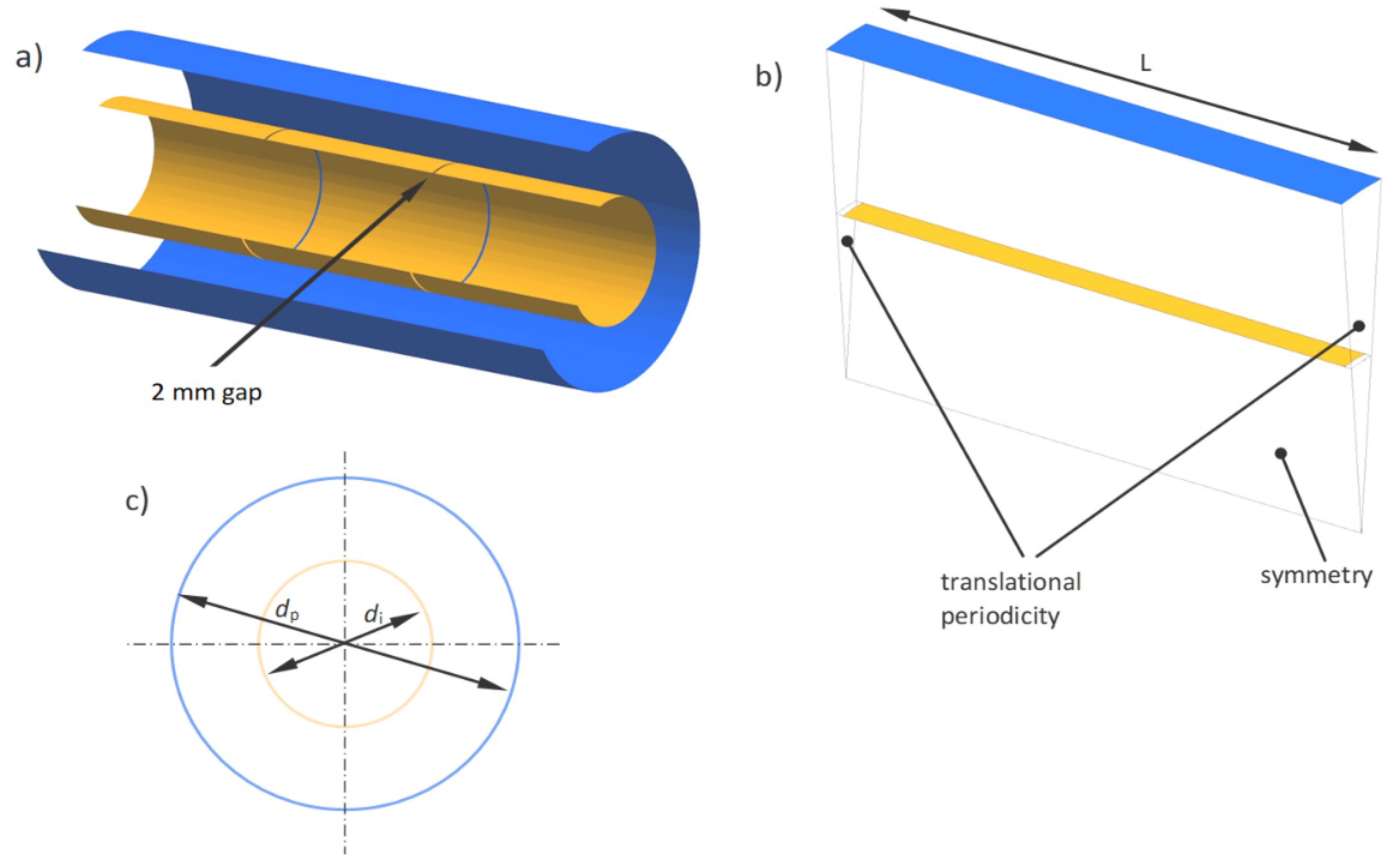
Numerical tests were conducted for various insert diameters di (Figure 2c) and a constant temperature difference ∆T = 100 °C between the wall and the average gas temperature in the pipe cross-section. On the outer wall of the channel, the heat transfer boundary condition of the first kind was applied, i.e., a constant wall temperature equal to 100 °C, while for gas, its mean volume temperature equal to 0 °C was a constant value. The working gas was the air with physical properties that were dependent on temperature.
In order to simplify the notation and the possibility of referencing other geometrical dimensions, the insert diameters di are presented in dimensionless form D = dp/di, with reference to the pipe diameter dp = 200 mm. The values of di and D, along with their final dimensions, are given in Table 1.
Due to the axial nature of the flow and the lack of a rotational velocity component in the flow, it is assumed that each tested insert can be considered as a two-dimensional case. Therefore, a computational domain in the shape of a longitudinal cylindrical slice with an aperture angle of 10° and length L = 152 mm was used in the simulations (Figure 2b), and the axial symmetry as the boundary conditions on the sides of the domain was set.
The appropriate method of conducting numerical simulations allowed the obtaining of a fully developed flow in this relatively short domain. In order to achieve this effect, the translational periodicity (as boundary conditions) at the inlet and outlet of the domain was set, and the fluid flow was forced with a pressure gradient. Thus, the computational domain has been reduced to a repeatable, periodic, and axisymmetric geometry representative of the entire channel. By reducing the domain size and the number of computational mesh nodes (up to 2D), it was possible to significantly shorten the computation time while maintaining the mesh’s high quality. This method of study has also been presented in [4,19,20,21], while other, less important details related to this method of numerical modelling are also presented in [15,16,17]. In order to ensure the same static pressure on both sides of the insert, slight gaps of 2 mm length in its continuity (Figure 2a) were applied, constituting about 1.5% of the total length of the insert.
For each insert, nine simulations were performed with different Reynolds numbers, resulting in 72 numerically tested cases, not counting the trial simulations. Based on the obtained results, thermal-flow characteristics of the tested inserts were prepared. Numerical simulations were performed with the ANSYS-CFX v18.2 calculation code.

4. Grid, Turbulence Model and Radiation Model

4.1. Governing Equations

Numerical calculations of the frictional resistance and the heat transfer were performed using the ANSYS-CFX code. During the calculations the basic equations of conservation of mass (1), momentum (2) and energy (3), which have the form [22], were solved:
ρ t + ( ρ U ¯ ) = 0
( ρ U ¯ ) t + ( ρ U ¯ × U ¯ ) = p + μ e ( U ¯ + ( U ¯ ) T 2 3 δ U ¯ ) + ( ρ ρ r e f ) g
( i t o t ρ ) t = ρ t + ( ρ U ¯ i t o t ) = ( k T ) + ( U ¯ τ w ) + S E
where the term ( U ¯ τ w ) represents the work of viscous forces, SE is a term of an energy source, and the total enthalpy itot is expressed as: i + 1 2 U ¯ 2 . For the turbulence model used, the governing equations are presented in detail in [16].

4.2. Grid Independence

Before the actual simulations, validation calculations for several geometries at different mesh densities were performed. Table 2 gives an example of the grid under test for one of the insert diameters, D = 0.4 and Re = 18,650. It was observed that the deviation between the grid elements of 25,440 and 49,820 is only 0.9% for the friction factor and 0.22% for the Nu number. Thus, for further calculations, a structural and hexagonal mesh (Figure 3) with 25,440 elements was chosen, which is the quality at which its further densification gives results differing by less than 1.5%.
For further calculations, a structured and hexagonal mesh, shown in Figure 3, was chosen with a quality at which further densification of the mesh gave results varying less than approximately1.5% for the most important flow parameters.
Of particular importance for flow and heat transfer phenomena is the hydraulic boundary layer. In the studied geometries, these layers form at the channel wall and on both sides of the insert, i.e., where the fluid contacts the solid. In these areas, the mesh was further compacted to obtain an appropriate y+ value for the turbulence model that was used [15,16,17,22,23].

4.3. Turbulence Model

Due to the assumed turbulent fluid flow, the SST k-ω (Shear Stress Transport) turbulence model was used in all of the numerical simulations. It is one of the most frequently used models in CFD applications due to its much better mapping of the flow-thermal phenomenon in calculations than the standard k-ε model [16,22]. The SST model’s main advantage is taking the viscous boundary sublayer into account by applying the k-ω model near the wall and using the standard k-ε model in the turbulent core region. A special function (the so-called blending function) implemented in the SST model [22] is responsible for selecting an appropriate model during the calculations.
One of the criteria for the numerical solution’s uniqueness was to achieve the appropriate convergence for the residues: momentum, energy, and turbulence. In all of the simulations, a convergence of 10 × 10−4 for the maximum residues and an order of magnitude lower (10 × 10−5) for mean residues (RMS—Root Mean Square) were obtained, both for the solutions of hydraulic equations and the energy equations. The second criterion for the solution’s uniqueness was stabilizing the flow-thermal parameters, such as velocity, pressure, and temperature, which were monitored both as average values and in several selected points in the computational domain. The computation process was terminated if the above parameters did not change for several consecutive iterations.

4.4. Radiation Model

For the radiative heat transfer calculations, shown in Figure 2c, the geometry of the tube with the insert can be treated as two infinitely long concentric cylinders with surfaces A1 and A2, emissivities ε1 and ε2, and temperatures T1 and T2 (where index 1 is referred to the smaller surface, i.e., the insert, and index 2 to the bigger surface, i.e., the pipe wall). For the tested geometries, where the outer cylinder completely surrounds the inner cylinder, it is assumed that the outer surface will intercept all radiation from the inner surface. Hence, considering the Stefan–Boltzman law for grey bodies, the net radiative heat flux transferred between these surfaces is described by Equation (4).
Q ˙ r a d = σ ( T 2 4 T 1 4 ) 1 ε 1 + A 1 A 2 ( 1 ε 2 1 ) = ε 12 σ ( T 2 4 T 1 4 )
where: ε 12 = 1 1 ε 1 + A 1 A 2 ( 1 ε 2 1 ) —interchange factor.
The above equation is the basic formula describing the radiative heat transfer for the studied geometry, and its derivation can be found in many literature sources, e.g., [24,25].
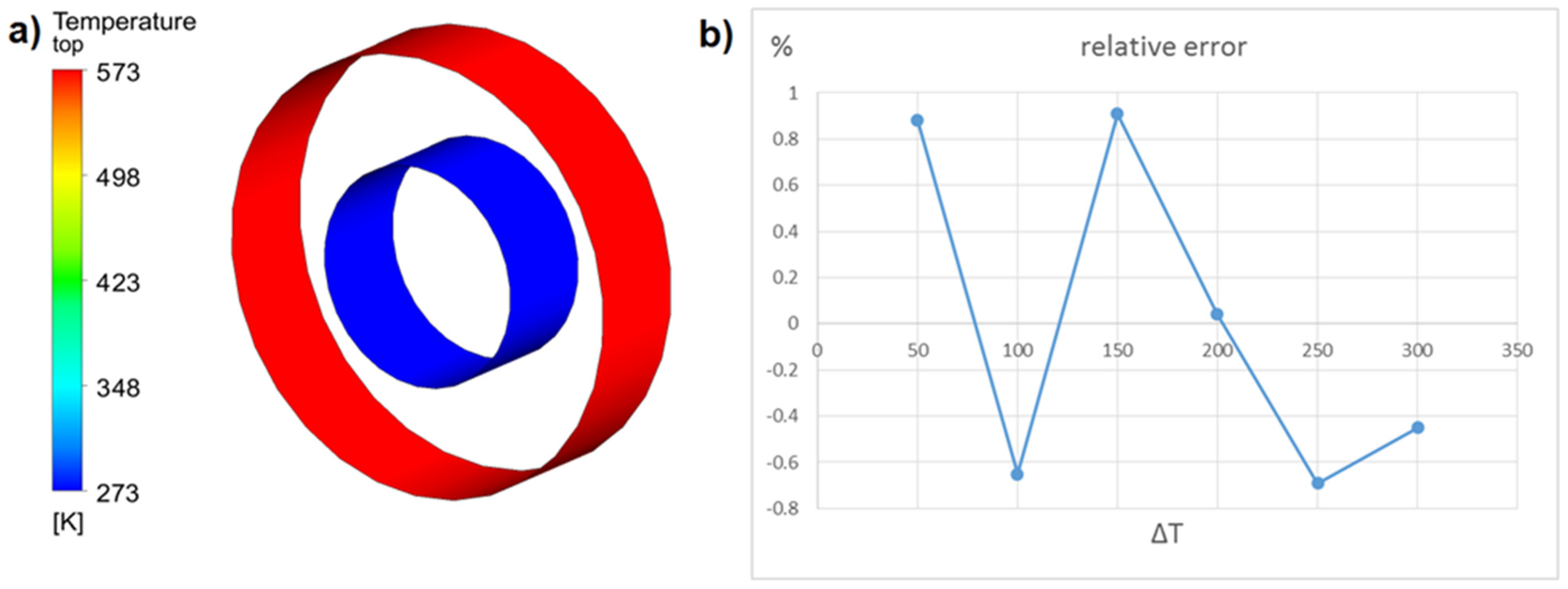
Using (4), a validation test for the selected insert geometry was performed, comparing the results obtained from the analytical calculations and numerical tests. The investigated quantity was the radiation heat flux exchanged between these surfaces for different pipe wall temperatures. The inner surface (Figure 4a) was kept at a constant temperature of 0 °C, while the outer surface temperature was changed every 50 °C. Both surfaces’ emissivities, both for this test and further numerical simulations, were the same and amounted to ε1 = ε2 = 0.9, while there was a vacuum between the surfaces to eliminate the effect of convection on heat transfer.
Due to very similar results, which would not be visible in the ordinary comparative chart, in Figure 4b, only the percentage difference of the heat fluxes in the form of the relative error calculated from (5) is shown.
δ = Q ˙ t h e o r y Q ˙ n u m e r i c a l Q ˙ t h e o r y 100 %
As shown in the diagram, the discrepancy in the value of the radiative heat flux transferred between the surfaces is within the limits of ±1% for the six temperature differences tested.
Several radiation models are available in the ANYS-CFX calculation program, such as Rosseland, P1, Discrete Transfer, and Monte Carlo. In a situation where the thermal energy of radiation is transferred between two surfaces, and the medium is transparent to radiation with wavelengths, which is where most of the heat transfer takes place, the Monte Carlo model is the only one that applies—and onlythis model was used in the simulations [20].

5. Hydraulic Characteristics—Friction Factor

5.1. Data Processing

The use of any insert in the flow channel always results in an increase in flow resistance. The situation is similar in the tested insert case, where the resistance increase is caused by the friction of the fluid against its two additional surfaces—outer and inner. As mentioned before, this kind of insert does not cause swirling and turbulisation of the fluid, which means that the flow resistances are much lower than in the case of inserts with a different construction and operation. These resistances mainly depend on the average gas velocity flow in the channel for a given insert diameter.
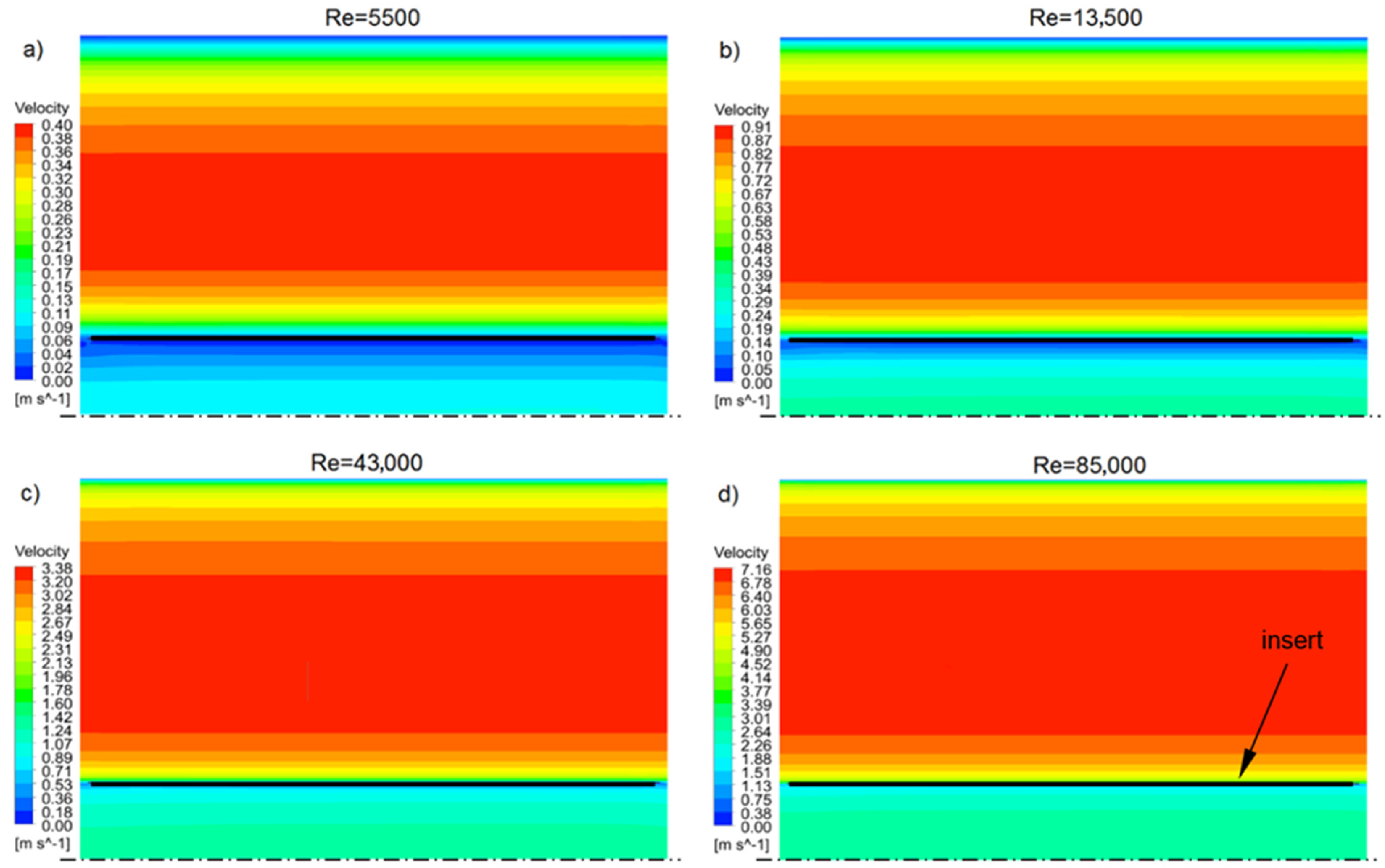
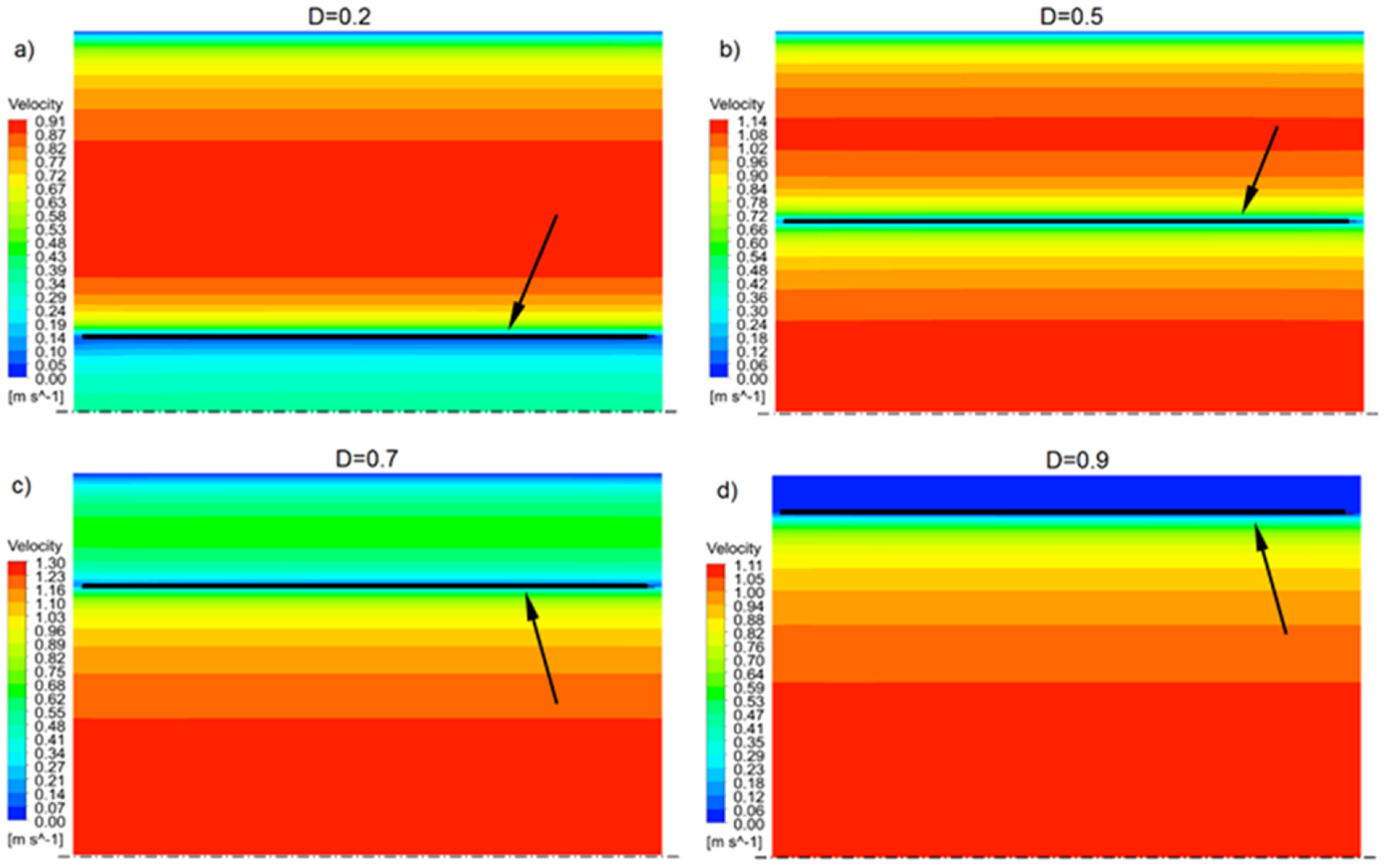
Figure 5 shows the velocity profiles in the symmetry plane (according to the diagram in Figure 2b) for an insert with a dimensionless diameter D = 0.2 and several Re numbers. Similarly, Figure 6 shows the velocity profiles for different dimensionless insert diameters D, but with the same number, Re = 13,500. By analysing the velocity fields shown, it can be concluded that the fluid velocities differ significantly in the inner and outer cross-section of the insert. These differences are due to the flow resistance and, as mentioned earlier, depend on the insert diameter and the Re number. As the flow resistance on both sides of the insert is the same, the gas flows in two streams, “adjusting” the velocity to the flow resistance. It can be assumed that in this way, there is a self-regulation of the amount of flowing medium outside and inside the insert.
To calculate the friction factor obtained from the numerical results, the Darcy–Weisbach Equation (6) was used:
f = 2 d p ρ u 2 d p d x
where the Re number is a function of the average velocity u in the pipe cross-section and the pipe diameter dp:
R e = u d p ν
The set value, forcing the fluid flow, was the pressure gradient dp/dx, while the average velocity in the pipe u resulted from numerical calculations. The friction factor for a smooth pipe was calculated using the Blassius formula (8):
f s = 0.3164 R e 0.25

5.2. Results and Discussion—Friction Factor

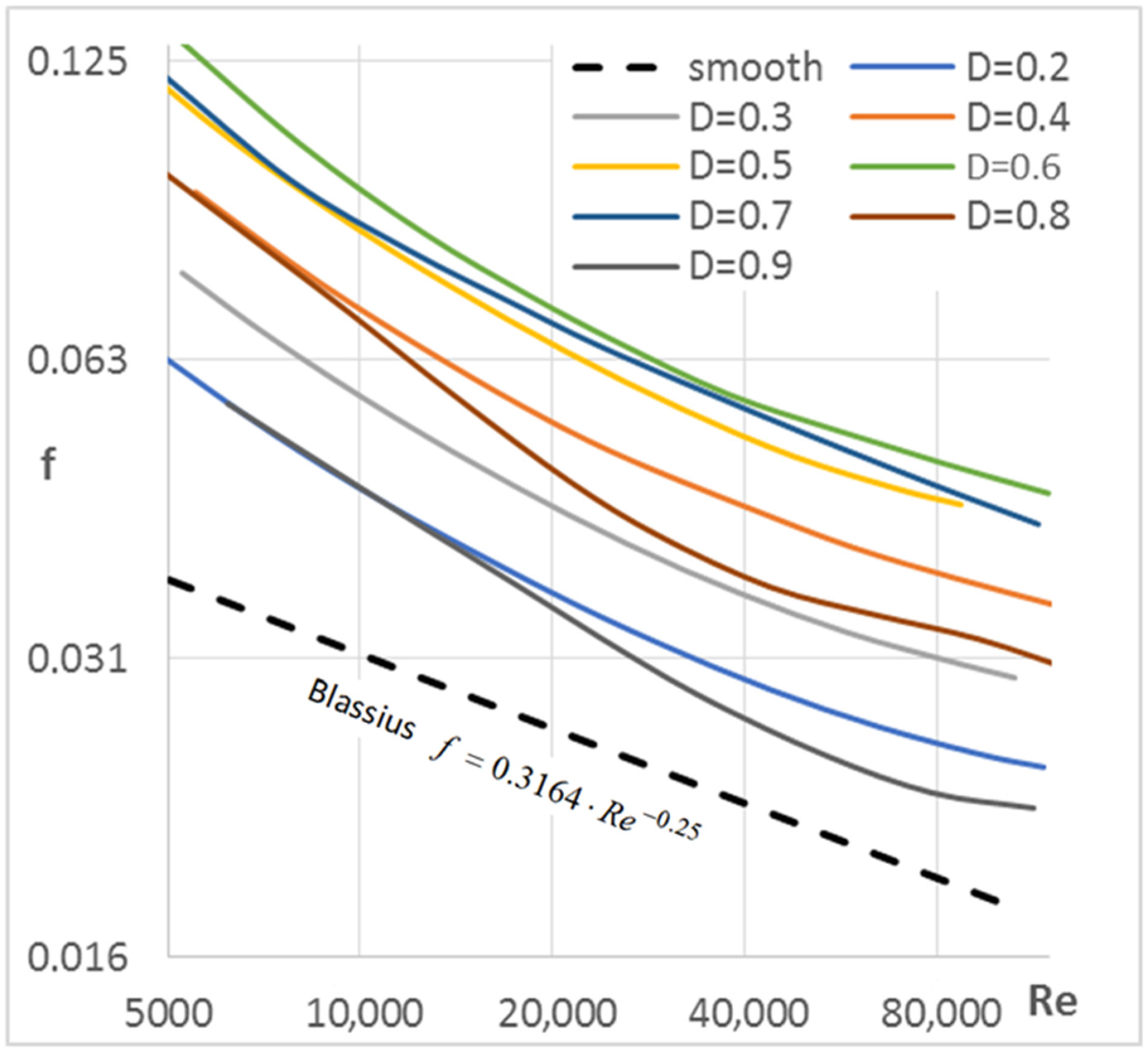
A total of nine numerical simulations for each geometry and different Reynolds numbers were performed. As mentioned earlier, the set amount forcing the flow was the pressure gradient dp/dx, and the average velocity in the pipe u was the result of the numerical calculations. In this way, the flow characteristics f(Re) for each insert geometry were prepared, while the friction factor was calculated from Equation (6). Figure 7 shows the characteristics of the friction factor as a function of Re for each tested insert diameter. Logarithmic scales were used on both axes, and the smooth pipe characteristics for comparison, calculated from (8), are also shown. As expected, for all insert sizes, the friction factor decreases as the Re number increases. The characteristics shown in the graph have a similar trend as the smooth pipe, but obviously different values.
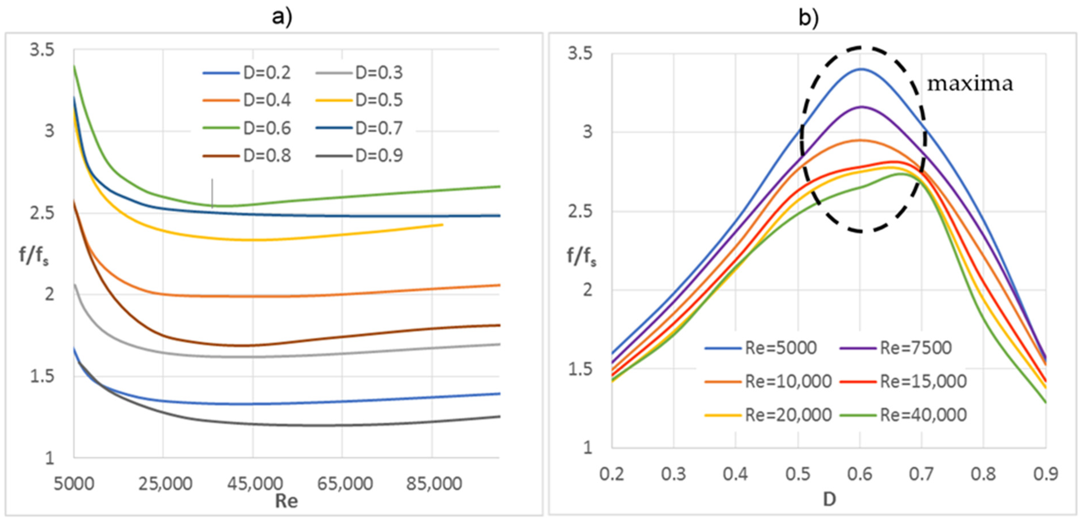
Figure 8a presents the ratio of f/fs as a Re number function, showing how many times the friction factor increased for a given insert diameter compared to the smooth pipe. As it can be seen, for all geometries, the largest increase occurs for the smallest Re numbers.
However, for larger Re numbers, from about 20,000 onwards, the characteristics align more or less horizontally or increase minimally, which means that these functions’ trends are similar to those of the smooth pipe. On the other hand, in Figure 8b, which shows the f/fs ratio as a function of the dimensionless insert diameter D, one can observe its effect on the friction factor value, according to several selected Re numbers. You can clearly see the maxima, exhibited by all of the characteristics in the D range from 0.5 to 0.7, which means that pipes with inserts of these diameters have the highest flow resistance.
However, compared to the turbulising flow inserts of other designs, e.g., those described in [26,27], the increase of the friction factor is several times smaller for the same Re numbers, which also translates to much smaller pressure drops.
In the aforementioned works, flow turbulising inserts were studied to improve heat transfer. Such inserts, in the form of twisted tape with cutouts that generate additional vortices during flow, specifically disrupt the flow and thus increase convective heat transfer, but at the same time, the flow resistance increases significantly.
The inserts studied in this paper do not disturb the flow because they have negligible thickness, are not equipped with vortex generators, and are arranged parallel to the flow direction. This design and the arrangement of the insert in the pipe result in much lower flow resistance and pressure drops than other inserts, while heat transfer enhancement takes place only through radiation.

6. Thermal Characteristics—Nusselt Number

6.1. Data Processing

In the simulation, the constant temperature of the pipes’ outer walls was assumed to be 100 °C (as the thermal boundary conditions), and the average gas temperature was assumed to be in the computational domain of 0 °C. This temperature difference was kept for all calculation cases in order to perform the tests under the same conditions. Due to the different flow conditions for each case, a different heat flux transferred to the fluid was obtained.
As mentioned earlier, the presented computational model obtained a fully developed, periodic flow at the inlet and outlet of the domain (forced by a pressure gradient). In order to obtain a fully developed thermal layer, and at the same time to maintain the energy balance in the system, the heat flux supplied by the wall to the gas domain had to be compensated by the use of an additional, equal in value, negative volumetric energy source that was different from the entire domain flow [16]. The working gas properties (air), such as thermal conductivity, viscosity, and density were functions of the temperature.
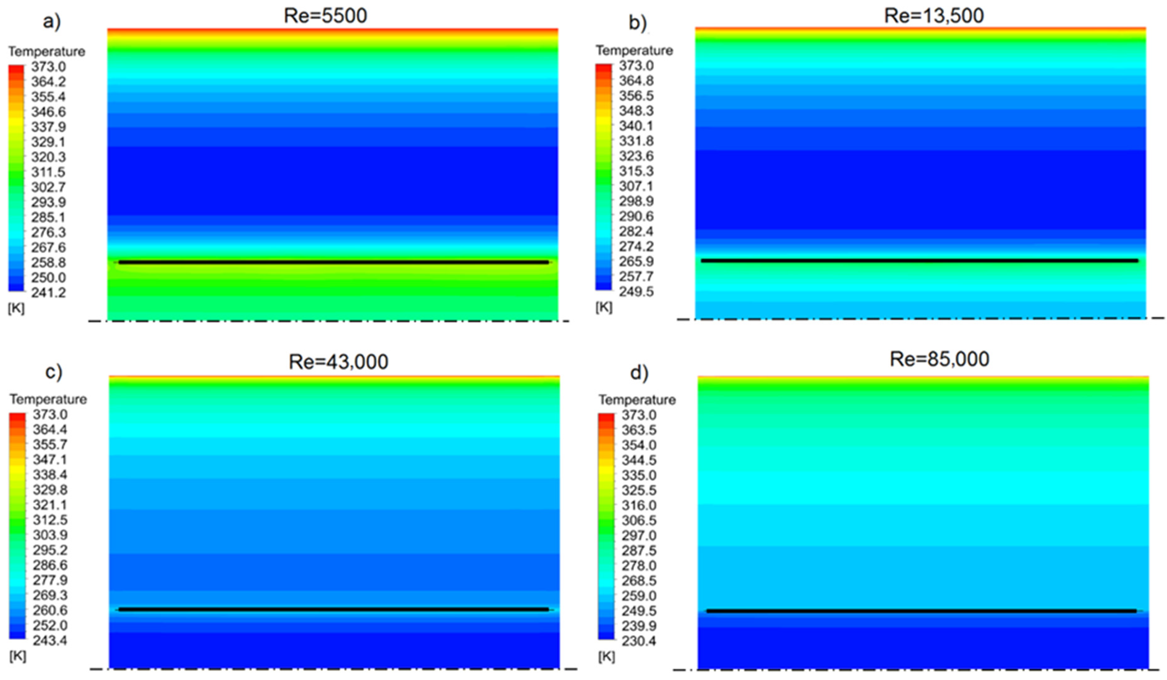
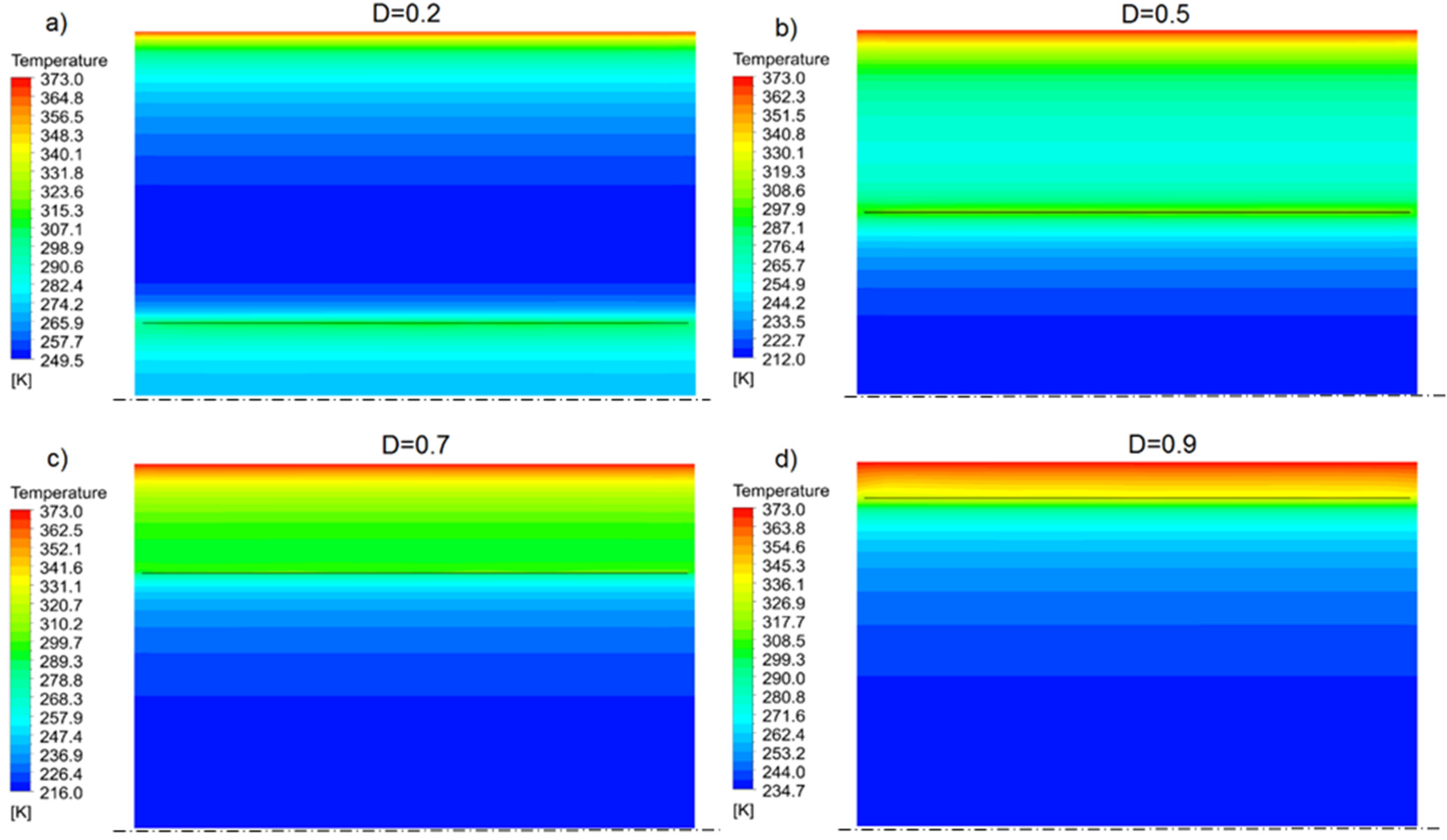
In Figure 9, in accordance with the diagram in Figure 2b, temperature profiles and several Re numbers, for example, the insert with dimensionless diameter D = 0.2, are shown. Similarly, Figure 10 shows the temperature profiles for several dimensionless diameters D of the inserts, but for the same number, Re = 13,500. As it can be seen, the temperature profiles in the inner and outer cross-sections of the insert differ significantly, highlighting the effects of radiation and the separation of the gas streams. The radiative heat flux transferred to the insert causes its heating, which allows this heat to be transferred to the fluid during convective heat transfer on both sides of the insert. To calculate the Nu number from the numerical analysis, the following relationship was used:
N u = Q ˙ tot d p k ( T w T b ) · A 2
While the Nu number for the smooth pipe without insert was calculated using the Dittus–Boelter correlation (10):
N u s = 0.023 · R e 0.8 · P r 0.4
As mentioned earlier, the insert divides the channel into two hydraulically independent spaces, except for small gaps for equalising static pressures (Figure 2a). This means that the fluids from the annular (outside the insert) and tubular (inside the insert) cross-section do not mix, but instead exchange heat energy among themselves through the insert’s thin wall. This situation significantly complicates the heat transfer calculation, i.e., the Nu number calculation, due to the problem’s two possible approaches.
The Nu number, calculated according to (9), characterises the heat transfer intensity on the flow channel wall—in this case, a round pipe. Therefore, calculating the temperature Tb can be related to either (a) the entire volume of the channel or (b) only the volume of the annular portion that actually contacts the channel wall. Both approaches have their justification.
Ad. (a) Tb calculated as the volume average temperature in the whole duct. This method of calculation is the most commonly used by most researchers, both for empty ducts and those equipped with inserts or other turbulators, e.g., [28,29,30,31,32,33,34]. The heat flux is transferred to the fluid that is in contact with the duct wall, and its average temperature is the result of the heat transfer conditions and the fluid velocity on both sides of the insert. One disadvantage of this approach with the considered insert is the lack of fluid mixing from the annular and tubular spaces. Thus, there are different velocity and temperature fields in these areas, and the temperature gradient in the duct wall layer is quite different from what it would be with a classical insert.
Ad. (b) Tb calculated as the volume average temperature from the annular part only. This approach is justified because the heat flux is directly transferred to the fluid in contact with the channel wall. Obviously, its average temperature is also affected by the amount of heat supplied to the insert by radiation and returned by the fluid’s insert due to convection to the annular and tubular parts.

6.2. Results and Discussion

According to the author, both ways of calculating the Nu number can be considered for this type of insert, even though they give different results. As it will be shown later in the paper, smaller values of Nu number are obtained using calculation method (a), i.e., taking the temperature in the whole volume of the pipe into account. In comparison, larger values are obtained using calculation method (b), i.e., only taking the annular part’s temperature into account.
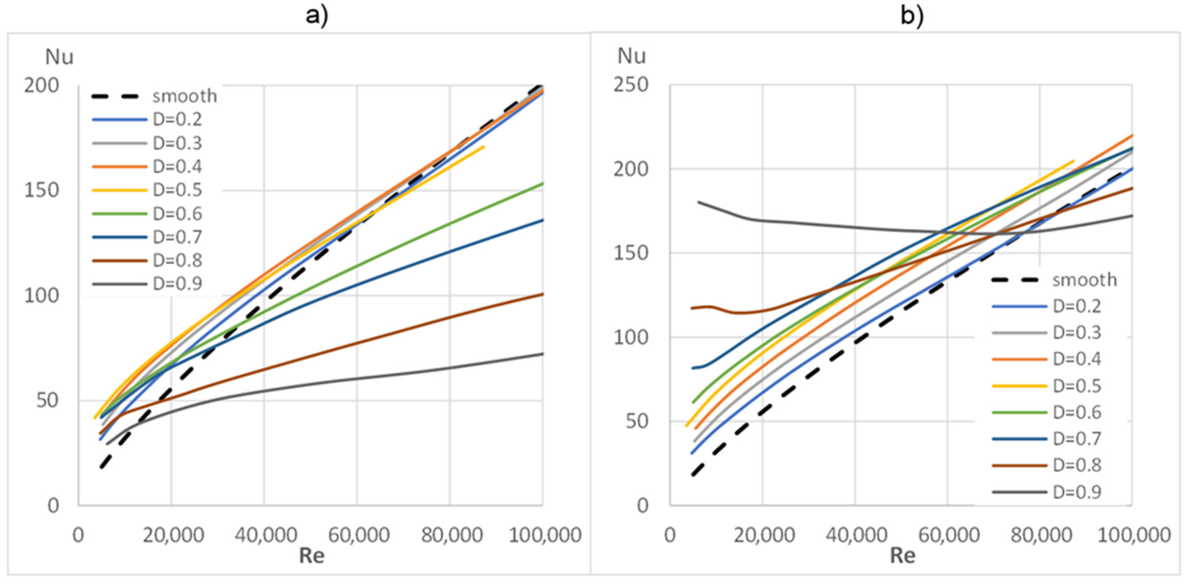
Figure 11 shows the characteristics of the Nu(Re) number calculated for methods (a) and (b), which additionally include the characteristics for a smooth pipe, calculated according to (7). It is clear that these charts differ quite significantly, both in terms of the value and the position of the curves. A characteristic feature is the values of the Nu numbers smaller than those of the smooth pipe, calculated using method (a), mainly for the largest diameters D = 0.9, 0.8, 0.7 and 0.6 (shown in Figure 11a), and calculated by method (b) in the range of large Re numbers and large insert diameters D = 0.9 and 0.8 (shown in Figure 11b). With normal turbulising inserts, such a phenomenon is unlikely to occur because any insert put into the pipe disrupts the flow by intensifying the convective heat flux while increasing the flow resistance.
Figure 11 shows the characteristics of the Nu(Re) number calculated for methods (a) and (b), which additionally include the characteristic for a smooth pipe, calculated according to (7). It is clear that these charts differ quite significantly, both in terms of the value and the position of the curves. A characteristic feature is the values of the Nu numbers smaller than those of the smooth pipe, calculated using method (a), mainly for the largest diameters D = 0.9, 0.8, 0.7 and 0.6 (shown in Figure 11a), and calculated by method (b) in the range of large Re numbers and large insert diameters D = 0.9 and 0.8 (shown in Figure 11b). With normal turbulising inserts, such a phenomenon is unlikely to occur because any insert put into the pipe would disrupt the flow by intensifying the convective heat flux while increasing the flow resistance.
In the case of the tested inserts, the appearance of Nu numbers smaller than the reference level, which would be for a smooth pipe, can be somehow explained by the creation of additional space between the pipe wall and the insert (annular cross-section). The larger the diameter of the insert, the smaller this space becomes, while at the same time, the average temperature of the gas in it increases, and its velocity decreases. This space gap can be treated as a kind of insulation layer between the pipe wall and the main flowing gas stream.
At small diameters, the insert is more or less evenly washed by the fluid on both sides. At large diameters, however, the mass flux of the flowing gas in the annular cross-section is much smaller than inside the insert, so the convective heat transfer decreases significantly, and the heat resistance from the conduction of the gas increases.
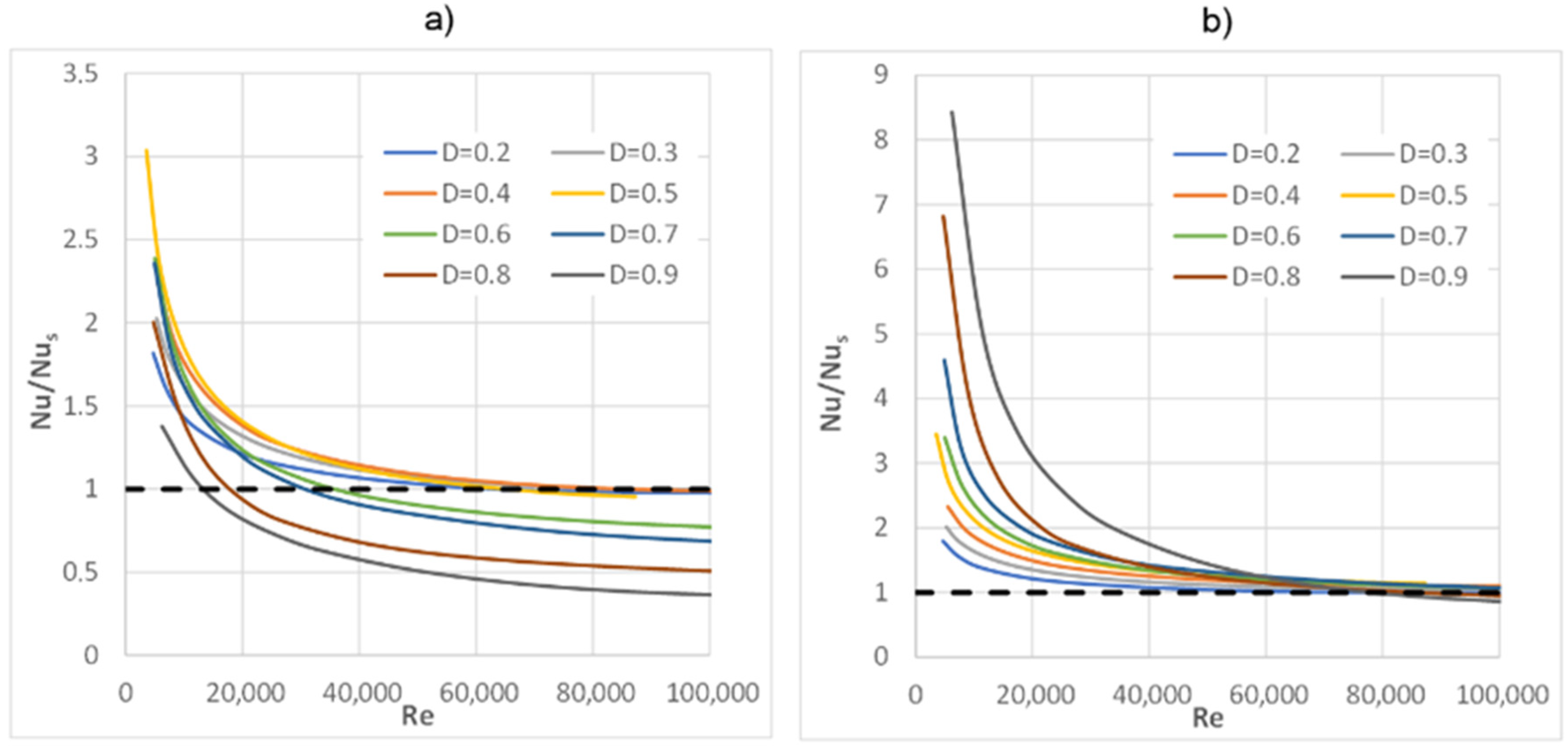
Figure 12a,b show the ratio of the Nu number of the tested inserts to the Nu number for a smooth pipe for the two above-mentioned calculation methods. Based on the average temperature Tb in the entire pipe (case a), it can be seen that for several inserts with diameters D = 0.9, 0.8, 0.7, 0.6, the values of the Nu/Nus characteristics are less than one. On the other hand, when only taking the temperature Tb for the calculations from the annular cross-section (case b), the curves are arranged in an “ideal” order, i.e., the intensification of heat transfer increases proportionally with the increase of the insert diameter.
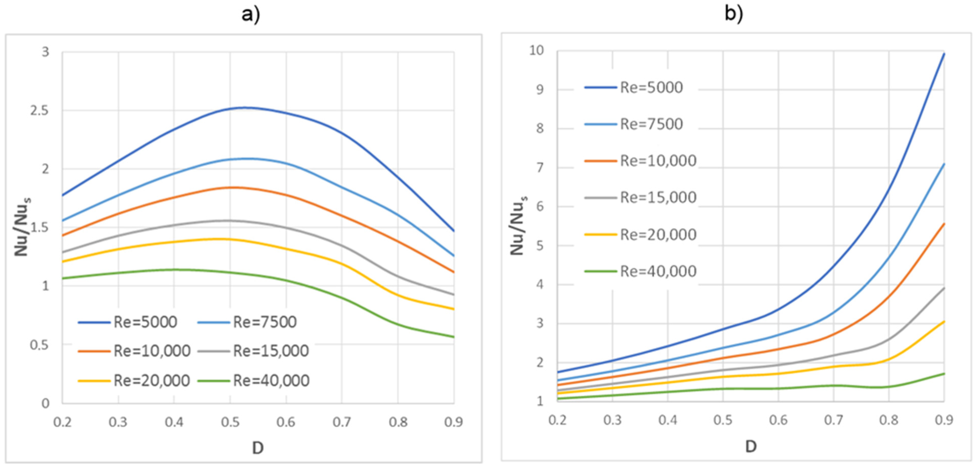
Figure 13 shows the Nu/Nus ratio as a function of the diameter D for several selected Re numbers, i.e., it illustrates the effect of the insert geometry on the heat transfer intensification. In Figure 13a, we can see a clear maximum that shows all of the characteristics at D = 0.5, which means that this is the largest increase in Nu number for this insert diameter in relation to the smooth pipe. These characteristics are very similar to the friction factors shown in Figure 8b.
When analysing Figure 13b, it was observed that along with increasing the insert diameter, the value of ratio Nu/Nus also increases, which is similar to what can be observed in Figure 12b.

7. Summary and Conclusions

This work presents numerical investigations for different diameters of an insert that absorbs radiative heat flux while simultaneously not turbulising the fluid. Based on these results, the characteristics of f(Re) and Nu(Re) were prepared and presented in graphs (Figure 7 and Figure 11). The characteristics of f/fs(Re) and Nu/Nus(Re) are also shown (in Figure 8 and Figure 12), i.e., the ratio of the friction factor and Nu numbers obtained from simulations, compared to a smooth pipe.
The velocity and temperature fields in the channel’s symmetry plane are also presented for a few exemplary insert geometries (Figure 6 and Figure 10) and a few Re numbers and constant diameters D (Figure 5 and Figure 9).
The analysis of the results allowed for the formulation of the following conclusions:
(1)
The highest increase in friction resistance (the friction factor ratio f/fs) was observed for inserts with diameters D = 0.5–0.7, while the lowest values were recorded for inserts with the smallest diameter D = 0.2 and the largest diameter D = 0.9;
(2)
The Nu number, which is the intensity of heat transfer, can be calculated in two ways that give different results. As mentioned earlier, there are two methods to determine the temperature Tb in formula (6). At the moment, the author suggests the “classical” way, (a), i.e., calculating the temperature Tb as an average over the entire volume channel. This method gives smaller, or one may say, “safer”, values of the Nu number than method (b). The Nu values obtained using method b) are quite large, up to about nine times larger than for a smooth pipe (for D = 0.9 and small Re numbers), but at relatively small velocities and pressure drops. Comparing the obtained results to the results of other insert geometries described in the available literature, it can be concluded that these are very high Nu numbers. Therefore, these values should be approached with caution, and the issue should still be thoroughly investigated and analysed;
(3)
The influence of radiation on heat transfer is shown in Figure 11 and Figure 12. Compared to a smooth pipe, the highest Nu numbers are noted for their small Re numbers. As the Re number increases, the difference between the Nu number of the tested inserts and that of a smooth pipe decreases quite quickly, and with large Re numbers, the Nu numbers of the values are comparable to those of a smooth pipe. This is a correct phenomenon because as the Re number and the gas flow velocity increase, the convective heat flux also increases, and the fraction of radiative heat flux decreases in the total heat flux, which is transferred from the wall to the fluid;
(4)
For the largest diameters D = 0.9, 0.8, 0.7, 0.6 (Figure 11a), a decrease in Nu numbers below the reference level, which is a smooth pipe, was observed. As previously mentioned, the tested insert does not turbulise the flow and therefore does not increase the convective heat flux. On the other hand, at larger insert diameters, the mainstream of fluid flows inside the insert, and the outer (annular) space becomes thinner, which causes a significant reduction in gas velocity in this region. As a result, the annular part, instead of participating in the heat transport to the gas, due to its low velocities, actually becomes an insulating layer inside the pipe. As it can be seen from the research, this phenomenon causes a deterioration of the overall heat transfer, even when compared to a smooth pipe.

Funding

This research received no external funding.

Institutional Review Board Statement

Not applicable.

Informed Consent Statement

Not applicable.

Data Availability Statement

Not applicable.

Conflicts of Interest

Author declares no conflict of interest.

Nomenclature

Aheat transfer area (m2)
diinsert diameter (m)
dppipe diameter (m)
Ddiameter ratio, (di/dp)
dp/dxpressure gradient (Pa/m)
ffriction factor
kthermal conductivity (W/mK)
Ldomain length (m)
NuNusselt number
Q ˙ tot total heat flux (W/m2)
Q ˙ rad radiative heat flux (W/m2)
Q ˙ conv convective heat flux (W/m2)
PrPrandtl number
ReReynolds number
Tbbulk temperature (K)
Twwall temperature (K)
uaverage velocity (m/s)
νkinematic viscosity (m2/s)
Ttemperature difference (K)
δrelative error (%)
εemissivity
ε12interchange factor
ρdensity (kg/m3)
indexes:
ssmooth tube
1for smaller heat transfer area
2for bigger heat transfer area

References

  1. Ozceyhan, V.; Gunes, S.; Buyukalaca, O.; Altuntop, N. Heat transfer enhancement in a tube using circular cross sectional rings separated from wall. Appl. Energy 2008, 85, 988–1001. [Google Scholar] [CrossRef]
  2. Min, C.; Qi, C.; Wang, E.; Tian, L.; Qin, Y. Numerical investigation of turbulent flow and heat transfer in a channel with novel longitudinal vortex generators. Int. J. Heat Mass Transf. 2012, 55, 7268–7277. [Google Scholar] [CrossRef]
  3. Lotfi, B.; Sundén, B.; Wang, Q. An investigation of the thermo-hydraulic performance of the smooth wavy fin-and-elliptical tube heat exchangers utilizing new type vortex generators. Appl. Energy 2016, 162, 1282–1302. [Google Scholar] [CrossRef]
  4. Jasiński, P. Numerical Study of Friction Factor and Heat Transfer Characteristics for Single-Phase Turbulent Flow in Tubes with Helical Micro-Fins. Arch. Mech. Eng. 2012, 59, 469–485. [Google Scholar] [CrossRef] [Green Version]
  5. Yeom, T.; Simon, T.; Zhang, T.; Zhang, M.; North, M.; Cui, T. Enhanced heat transfer of heat sink channels with micro pin fin roughened walls. Int. J. Heat Mass Transf. 2016, 92, 617–627. [Google Scholar] [CrossRef] [Green Version]
  6. Liu, G.; Yang, C.; Zhang, J.; Zong, H.; Xu, B.; Qian, J.-Y. Internal Flow Analysis of a Heat Transfer Enhanced Tube with a Segmented Twisted Tape Insert. Energies 2020, 13, 207. [Google Scholar] [CrossRef] [Green Version]
  7. Wijayanta, A.T.; Mirmanto, P.; Kristiawan, B.; Aziz, M. Internal Flow in an Enhanced Tube Having Square-cut Twisted Tape Insert. Energies 2019, 12, 306. [Google Scholar] [CrossRef] [Green Version]
  8. Bellos, E.; Tzivanidis, C. Enhancing the Performance of Evacuated and Non-Evacuated Parabolic Trough Collectors Using Twisted Tape Inserts, Perforated Plate Inserts and Internally Finned Absorber. Energies 2018, 11, 1129. [Google Scholar] [CrossRef] [Green Version]
  9. Mwesigye, A.; Bello-Ochende, T.; Meyer, J.P. Heat transfer and thermodynamic performance of a parabolic trough receiver with centrally placed perforated plate inserts. Appl. Energy 2014, 136, 989–1003. [Google Scholar] [CrossRef] [Green Version]
  10. Cerón, J.F.; Pérez-García, J.; Solano, J.P.; García, A.; Herrero-Martín, R. A coupled numerical model for tube-on-sheet flat-plate solar liquid collectors. Analysis and validation of the heat transfer mechanisms. Appl. Energy 2015, 140, 275–287. [Google Scholar] [CrossRef]
  11. Luo, L.; Wen, F.; Wang, L.; Sundén, B.; Wang, S. Thermal enhancement by using grooves and ribs combined with delta-winglet vortex generator in a solar receiver heat exchanger. Appl. Energy 2016, 183, 1317–1332. [Google Scholar] [CrossRef]
  12. Eiamsa-Ard, S.; Promvonge, P. Thermal characterization of turbulent tube flows over diamond-shaped elements in tandem. Int. J. Therm. Sci. 2010, 49, 1051–1062. [Google Scholar] [CrossRef]
  13. Kongkaitpaiboon, V.; Nanan, K.; Eiamsa-Ard, S. Experimental investigation of convective heat transfer and pressure loss in a round tube fitted with circular-ring turbulators. Int. Commun. Heat Mass Transf. 2010, 37, 568–574. [Google Scholar] [CrossRef]
  14. Aydin, D. Heat transfer and exergy loss in cut out conical turbulators. Energy Convers. Manag. 2004, 45, 785–796. [Google Scholar]
  15. Jasiński, P.B. Numerical study of thermal-hydraulic characteristics in a circular tube with ball turbulators. Part 1: PIV experiment and pressure drop. Int. J. Heat Mass Transf. 2014, 74, 48–59. [Google Scholar] [CrossRef]
  16. Jasiński, P.B. Numerical study of thermal-hydraulic characteristics in a circular tube with ball turbulators. Part 2: Heat transfer. Int. J. Heat Mass Transf. 2014, 74, 473–483. [Google Scholar] [CrossRef]
  17. Jasiński, P. Numerical study of thermo-hydraulic characteristics in a circular tube with ball turbulators. Part 3: Thermal performance analysis. Int. J. Heat Mass Transf. 2017, 107, 1138–1147. [Google Scholar] [CrossRef]
  18. Bas, H.; Ozceyhan, V. Heat transfer enhancement in a tube with twisted tape inserts placed separately from the tube wall. Exp. Therm. Fluid Sci. 2012, 41, 51–58. [Google Scholar] [CrossRef]
  19. Jasiński, P. Numerical optimization of flow-heat ducts with helical micro-fins, using Entropy Generation Minimization (EGM) method. In Proceedings of the WSEAS International Conferences (HTE’11), Florence, Italy, 23–25 August 2011; pp. 47–54. [Google Scholar]
  20. Fodemski, T.; Górecki, G.; Jasiński, P. Corrugated channels heat transfer efficiency Analysis based on velocity fields resulting from computer simulation and PIV Measurements. In Proceedings of the 8th International Conference on Heat Transfer, Fluid Mechanics and Thermodynamics, HEFAT 2011, Pointe Aux Piments, Mauritius, 11–13 July 2011. [Google Scholar]
  21. Li, X.-W.; Meng, J.-A.; Guo, Z.-Y. Turbulent flow and heat transfer in discrete double inclined ribs tube. Int. J. Heat Mass Transf. 2009, 52, 962–970. [Google Scholar] [CrossRef]
  22. ANSYS-CFX Manual v. 18.1. Available online: http://www.ansys.com (accessed on 25 July 2021).
  23. Gutkowski, A.N.; Łęcki, M.; Jasiński, P.; Jędrowiak, B. Flame behavior during propagation in small isothermal tubes characterized by different degrees of the end opening. Combust. Sci. Technol. 2018, 191, 711–725. [Google Scholar] [CrossRef]
  24. Karwa, R. Heat and Mass Transfer; Springer: Berlin/Heidelberg, Germany, 2016. [Google Scholar]
  25. Fakheri, A. Intermediate Heat Transfer; Taylor & Francis: Abingdon, UK, 2014. [Google Scholar]
  26. Arjmandi, H.; Amiri, P.; Pour, M.S. Geometric optimization of a double pipe heat exchanger with combined vortex generator and twisted tape: A CFD and response surface methodology (RSM) study. Therm. Sci. Eng. Prog. 2020, 18, 100514. [Google Scholar] [CrossRef]
  27. Wijayanta, A.T.; Yaningsih, I.; Aziz, M.; Miyazaki, T.; Koyama, S. Double-sided delta-wing tape inserts to enhance convective heat transfer and fluid flow characteristics of a double-pipe heat exchanger. Appl. Therm. Eng. 2018, 145, 27–37. [Google Scholar] [CrossRef]
  28. Zheng, N.; Liu, P.; Wang, X.; Shan, F.; Liu, Z.; Liu, W. Numerical simulation and optimization of heat transfer enhancement in a heat exchanger tube fitted with vortex rod inserts. Appl. Therm. Eng. 2017, 123, 471–484. [Google Scholar] [CrossRef]
  29. Huanga, S.; Chena, H.; Zhang, X. Experimental evaluation of thermal performance in a circular tube with Y-branch insert. Int. Commun. Heat Mass Transf. 2019, 106, 15–21. [Google Scholar] [CrossRef]
  30. Bhuiyaa, M.; Ahamed, J. Heat transfer enhancement and development of correlation for turbulent flow through a tube with triple helical tape inserts. Int. Commun. Heat Mass Transf. 2012, 39, 94–101. [Google Scholar] [CrossRef]
  31. Hasanpour, A.; Farhadi, M.; Sedighi, K. A review study on twisted tape inserts on turbulent flow heat exchangers: The overall enhancement ratio criteria. Int. Commun. Heat Mass Transf. 2014, 55, 53–62. [Google Scholar] [CrossRef]
  32. Jasiński, P.; Kowalczyk, M.; Romaniak, A.; Warwas, B.; Obidowski, D.; Gutkowski, A. Investigation of Thermal-Flow Characteristics of Pipes with Helical Micro-Fins of Variable Height. Energies 2021, 14, 2048. [Google Scholar] [CrossRef]
  33. Ho, C.; Liu, Y.-C.; Yang, T.-F.; Ghalambaz, M.; Yan, W.-M. Convective heat transfer of nano-encapsulated phase change material suspension in a divergent minichannel heatsink. Int. J. Heat Mass Transf. 2021, 165, 120717. [Google Scholar] [CrossRef]
  34. Ho, C.; Liu, Y.-C.; Ghalambaz, M.; Yan, W.-M. Forced convection heat transfer of Nano-Encapsulated Phase Change Material (NEPCM) suspension in a mini-channel heatsink. Int. J. Heat Mass Transf. 2020, 155, 119858. [Google Scholar] [CrossRef]
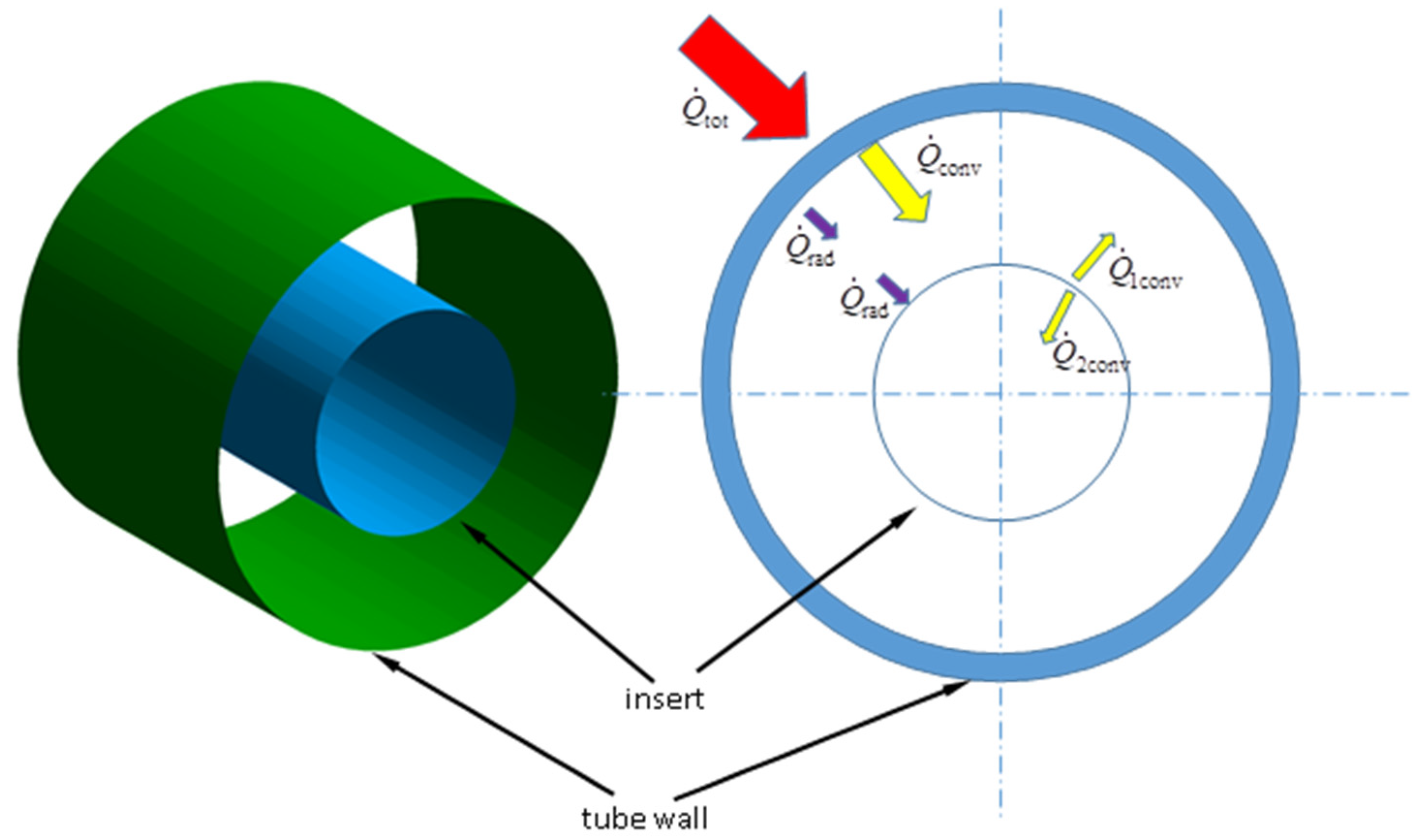
Figure 1. A fragment of a pipe with an insert and a schematic view of heat fluxes.
Energies 14 04596 g001
Figure 2. Repeatable insert segment: (a) 3D view of the pipe section with insert, (b) computational domain, (c) channel cross-section diagram.
Energies 14 04596 g002
Figure 3. Computational mesh with densification areas at the walls.
Energies 14 04596 g003
Figure 4. (a) View of the tested geometry, 1-insert, 2-pipe; (b) relative error of radiation fluxes.
Energies 14 04596 g004
Figure 5. Velocity profiles in the symmetry plane for dimensionless insert diameter D = 0.2 and different Re numbers: (a) Re = 5500, (b) Re = 13,500, (c) Re = 43,000 and (d) Re = 85,000.
Energies 14 04596 g005
Figure 6. Velocity profiles in the symmetry plane for several dimensionless diameters D of the insert and the same number Re = 13,500. (a) D = 0.2, (b) D = 0.5, (c) D = 0.7, (d) D = 0.9.
Energies 14 04596 g006
Figure 7. Friction factor f(Re) for dimensionless insert diameters D.
Energies 14 04596 g007
Figure 8. (a) f/fs(Re) ratio for dimensionless insert diameters D; (b) f/fs(D) ratio for several Re numbers.
Energies 14 04596 g008
Figure 9. Temperature profiles in the symmetry plane for a dimensionless insert diameter D = 0.2 and several Re numbers: (a) Re = 5500, (b) Re = 13,500, (c) Re = 43,000 and (d) Re = 85,000.
Energies 14 04596 g009
Figure 10. Schemes follow the same formatting. Temperature profiles in the symmetry plane for several dimensionless insert diameters D and the same number Re = 13,500. (a) D = 0.2, (b) D = 0.5, (c) D = 0.7, (d) D = 0.9.
Energies 14 04596 g010
Figure 11. Nusselt number Nu(Re) as a function of Re number, calculated on the basis of the average temperature: (a) from the entire pipe; (b) from the annular section of pipe.
Energies 14 04596 g011
Figure 12. The ratio of the Nu number obtained from simulation to the Nu number for a smooth pipe Nu/Nus(Re) as a function of the Re number, calculated on the basis of the average temperature: (a) from the entire pipe; (b) from the annular cross-section.
Energies 14 04596 g012
Figure 13. Nu/Nus(D) ratio for several Re numbers, calculated from the average temperature: (a) from the whole pipe; (b) from the annular section.
Energies 14 04596 g013
Table 1. Dimensions of the tested insert and the corresponding dimensionless diameters.
di [mm]406080100120140160180
D [—]0.20.30.40.50.60.70.80.9
Table 2. Grid independent test for Re = 18,650 and insert diameter D = 0.4.
No. of ElementsfDev. %NuDev. %
61400.0461-73.23-
11,9600.05089.3878.056.18
18,2300.05436.3280.132.60
25,4400.05511.4580.620.61
49,8200.05560.980.800.22
Publisher’s Note: MDPI stays neutral with regard to jurisdictional claims in published maps and institutional affiliations.