
Selected Issues of Safe Operation of the Railway Traffic Control System in the Event of Exposition to Damage Caused by Lightning Discharges


Abstract
:1. Introduction
2. Materials and Methods
2.1. Lightning Risk Management According to PN-EN 62305-2:2012
- R1: Risk of loss of life or permanent injury L1;
- R2: Risk of loss of service to the public L2;
- R3: Risk of loss of cultural heritage L3;
- R4: Risk of loss of economic value L4.
- NX—Number of dangerous events related to particular source and type of damage (Table 1);
- PX—Probability of damage caused by one dangerous event of a particular source of damage;
- LX—Loss factor that allows estimating the loss related to the damage.
- Identify the components RX forming the risk R;
- Calculate the components RX and the entire risk R;
- Identify the value of the tolerated risk RT, based on recommendations of applicable standards or bodies having jurisdiction;
- Compare the calculated risk R with the tolerated value RT.
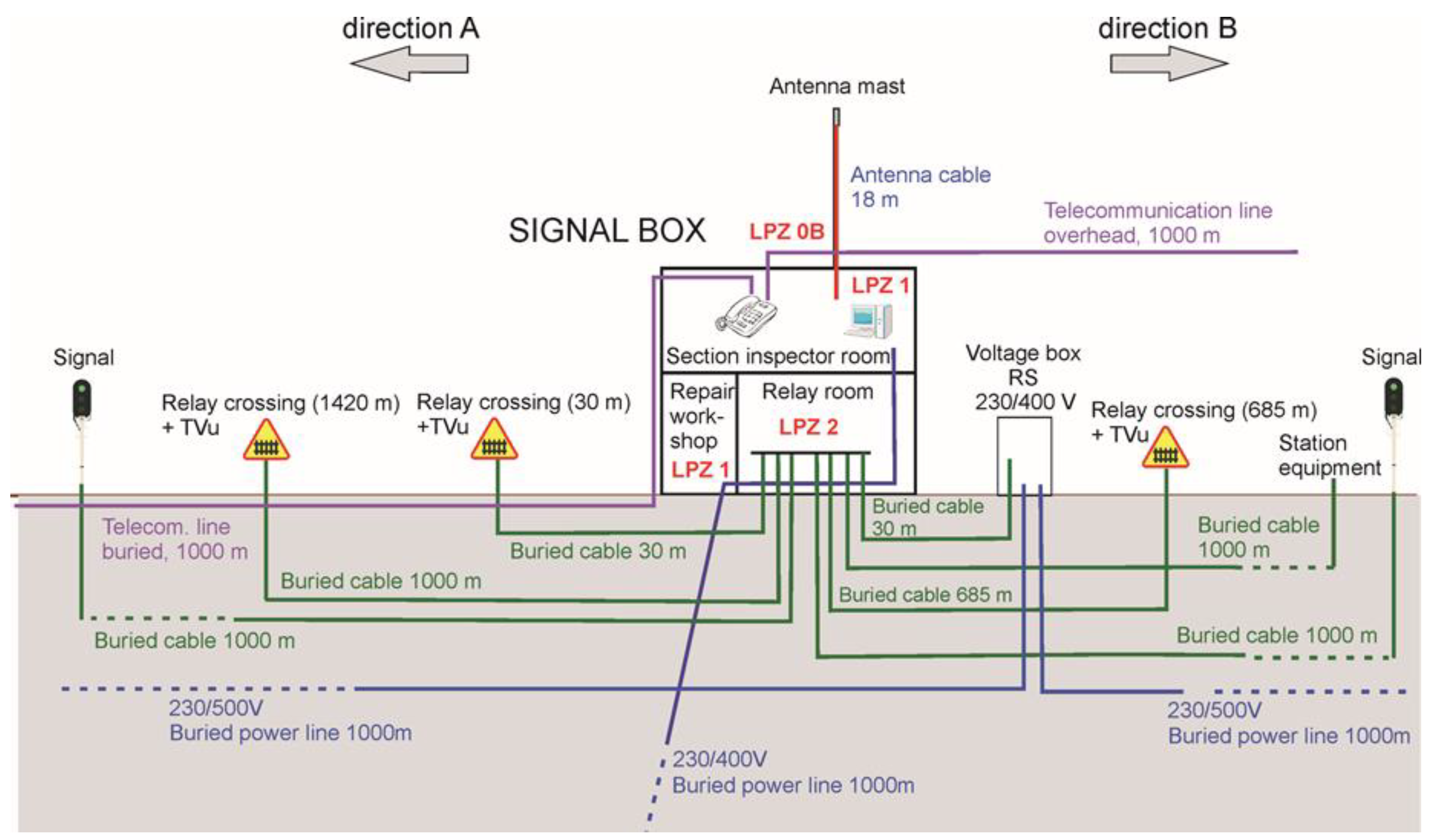
2.2. Application of PN-EN 62305-2:2012 Lightning Risk Procedure to the Case Study—The Railway Object
- electrical power feeding line 230/400 V connected to the low voltage power system;
- two telecommunication lines;
- antenna cable connected to the antenna installed on a mast at the roof;
- two feeding lines 230/500 V of automatic line block system;
- three control lines of automatic level crossings;
- two signal lines for remote signaling;
- signal line connected to station equipment.
- For LPZ 0A or 0B (outside the signal box):▪ Z1—around the signal box, access from the ground;▪ Z2—around the antenna mast, access from the roof of the signal box;
- For LPZ 1 (inside the signal box):▪ Z3—section inspector auty room;▪ Z4—repair workshop room;
- For LPZ 2 (inside the signal box with better shielding properties than LPZ 1 if needed):▪ Z5—relay room.
- LPZ 0A: Zone unprotected against lightning electromagnetic pulse.
- LPZ 0B: Zone protected against direct lightning strikes by external lightning protection system (LPS). Equipment is exposed to parts of lightning currents and full lightning electromagnetic fields.
- LPZ 1: Internal zone, where the failure surge currents and voltages are limited by equipotential bonding and surge protective devices (SPD), and the lightning electromagnetic field is attenuated by spatial shielding at the zone boundary.
- LPZ 2…n: Internal zones, where current and voltage impulses are further limited by equipotential bonding and additional SPD, and the lightning electromagnetic field is further limited by additional spatial shielding at the zones’ boundaries.
- External lightning protection system (LPS) on the object—no external LPS present;
- Protection against electric shock due to direct lightning flash to the object—no protection;
- Screening effectiveness of the structure at the boundary LPZ 0/1—no shielding;
- Screening effectiveness of internal shields, i.e., within LPZ 1—no internal shielding;
- Type, shielding, grounding, and isolation conditions of the incoming lines:
- antenna cable line—telecommunication (TLC), aerial, shielded with shield resistance higher than 5 Ω/km up to 20 Ω/km, no connection at the entrance (internal system);
- electrical power feeding line 230/400 V—power, buried, unshielded;
- electrical power feeding lines 230/500 V—power, buried unshielded;
- telecommunication line 1—TLC, buried, unshielded;
- telecommunication line 2—TLC, aerial, unshielded;
- control lines of automatic level crossings (1, 2, and 3)—TLC/data, buried, unshielded;
- signal line for station equipment—TLC/data, buried, unshielded;
- signal lines for remote signaling (1 and 2)—TLC/data, buried, unshielded;
- Type of internal wiring of the internal electrical and electronic systems:
- antenna system—shielded;
- electrical power 230/400 V—unshielded, routing precautions to avoid large loops;
- electrical power 230/500 V—unshielded, routing precautions to avoid large loops;
- telecommunication (1 and 2)—unshielded, routing precautions to avoid large loops;
- control of level crossings (1, 2, 3)—unshielded, routing precautions to avoid large loops;
- station equipment—unshielded, routing precautions to avoid large loops;
- remote signaling (1, 2)—unshielded, routing precautions to avoid large loops;
- Lowest impulse withstand voltage—from 1.0 kV to 2.5 kV, depending on the zone and the internal system;
- Protection against electric shock due to direct lightning flash to the incoming lines—electrical insulation and/or physical restrictions, depending on the zone and the incoming line;
- Coordinated surge protective devices (SPDs) in the internal electrical and electronic systems, according to PN-EN 62305-4 [23]—no coordinated SPDs in all systems and zones;
- Equipotential bonding provided by SPDs at the entry of the incoming lines to the object, according to PN-EN 62305-3 [22]—no SPDs in all systems and zones.
- Calculating the equivalent collection areas of lightning flashes to and near the external lines (power, telecom, data) incoming to the object following the same or similar routes when collection areas of particular lines overlap (Table 2), and selecting the worst case characteristics (Table A13, Table A14 and Table A15) for estimating the probabilities of damage;
- Proposing the typical mean values of losses of service to the public and of economic value due to physical damage LF and failures of internal electrical and electronic systems LO, which can be regarded specific for the objects (Table 4);
- Proposing the typical mean value of loss of human life due to failures of internal electrical and electronic systems for people present in the dangerous place outside the object (zone ZE) LOE (Table 4) and the time of presence of people in the place te (Table 5), and calculating the corresponding risk of loss of human life in the outside zone ZE;
- Proposing the numbers of users served by the object, relevant to the loss of service to the public, as specific to the considered objects (Table 6);
- Proposing the economic value of the object and its content, relevant to the economic loss, as specific to the considered objects (Table 7).
3. Results
3.1. Object without Protection Measures—Base Case
3.2. Selection of Protection Measures and Its Characteristics—Object with Protection Measures
4. Discussion
- Calculating the equivalent collection areas in the case when several lines incoming to the object follow the same or similar routes and selecting the worst case characteristics for estimation of probability parameters.
- Taking into account and evaluating the amount of loss of human life due to failures of RTC systems for people present in dangerous places outside the object. The typical mean value of loss LOE was assumed as 10 times lower than for less significant parts of the hospital and the yearly time of presence of people in the dangerous places was taken as 1/3 of the year.
- Proposing the mean values of loss of public service due to physical damage and failures of RTC systems. The loss factors were assumed the same as for TV and telecommunication objects.
- Proposing the mean values of economic loss due to physical damage and failures of RTC systems. The loss factors were assumed near or lower as for industrial and commercial objects.
- Proposing the number of users served by the object, relevant to the loss of service to the public.
- Estimating the economic value of the object and its content relevant to the economic loss, according to PN-EN 62305-2:2012 using the lowest reference value for typical industrial structures.
5. Conclusions
Author Contributions
Funding
Institutional Review Board Statement
Informed Consent Statement
Data Availability Statement
Conflicts of Interest
List of Symbols and Abbreviations
| AD (m2) | equivalent collection area for lightning flashes to an isolated object (structure), |
| AL (m2) | equivalent collection area for lightning flashes to a line, |
| AI (m2) | equivalent collection area for lightning flashes near a line, |
| ADJ (m2) | equivalent collection area of direct lightning flashes to an adjacent structure, |
| AM | equivalent collection area for lightning flashes striking near a structure, |
| ca | value of the animals, in currency, |
| cb | value of the building, in currency, |
| cc | value of the content of an object, in currency, |
| CD | location factor, |
| CE | environmental factor, |
| CDJ | location factor of an adjacent structure, |
| CLD | factor depending on shielding, grounding, and isolation conditions of the line for lightning flashes to a line, |
| CLI | factor depending on shielding, grounding, and isolation conditions of the line for lightning flashes near a line, |
| CI | installation factor, |
| cs | value of the internal systems (including their activities), in currency, |
| ct | total value of a structure, in currency, |
| CT | line type factor for an HV/LV transformer on the line, |
| D1 | injury to living beings by electric shock, |
| D2 | physical damage, |
| D3 | failure of internal system, |
| EB | equipotential bonding, |
| EMC | Electromagnetic compatibility, |
| GPS | Global Positioning System, |
| H (m) | height of the structure, |
| hz | factor increasing the loss when a special hazard is present, |
| KS1 | factor relevant to the screening effectiveness of the object, |
| KS2 | factor relevant to the screening effectiveness of shields internal to the object, |
| KS3 | factor relevant to the characteristics of internal wiring, |
| KS4 | factor relevant to the impulse withstand voltage of internal system, |
| L (m) LL (m) | length of an object, length of a line, |
| L1 | loss of human life, |
| L2 | loss of service to the public, |
| L3 | loss of cultural heritage, |
| L4 | loss of economic value, |
| LA | loss due to injury to living beings by electric shock (flashes to the object), |
| LB | loss due to physical damage (flashes to the object), |
| LC | loss related to failure of internal systems (flashes to the object), |
| LM | loss related to failure of internal systems (flashes near the object), |
| LF | typical mean amount of loss in a structure due to physical damage, |
| LO | typical mean amount of loss in a structure due to failure of internal systems, |
| LT | typical mean amount of loss in a structure due to injury by electric shock, |
| LU | loss in a structure due to injury by electric shock (flashes to a line), |
| LV | loss in a structure due to physical damage (flashes to a line), |
| LW | loss in a structure due to failure of internal systems (flashes to a line), |
| LZ | loss in a structure due to failure of internal systems (flashes near a line), |
| LINET (TOA) | Lightning Detection Network (Time-of-Arrival), |
| LPL | lightning protection level number related to a set of values of lightning current parameters relevant to the probability that the associated maximum and minimum design values will not be exceeded in naturally occurring lighting, |
| LPZ | lightning protection zone where the lightning electromagnetic environment is defined, |
| LPS | lightning protection system (complete system used to reduce physical damage due to lightning flashes to a structure), |
| ND | number of dangerous events due to flashes to a structure (expected average annual number of dangerous events due to lightning flashes to a structure), |
| NDJ | number of dangerous events due to flashes to an adjacent structure, |
| Ng | lightning ground flash density (number of lightning discharges to ground per square kilometer per year), |
| NI | number of dangerous events due to flashes near a line, |
| NL | number of dangerous events due to flashes to a line, |
| NM | number of dangerous events due to flashes near a structure, |
| NTL | non-traction line, |
| nt | expected total number of persons (or users served), |
| nz | number of possible endangered persons (victims or users not served), |
| PA | probability of injury to living beings by electric shock (flashes to a structure), |
| PB | probability of physical damage to a structure (flashes to a structure), |
| PC | probability of failure of internal systems (flashes to a structure), |
| PLD | probability reducing PU, PV, and PW depending on line characteristics and withstand voltage of equipment (flashes to a line), |
| PLI | probability reducing PZ depending on line characteristics and withstand voltage of equipment (flashes near a line), |
| PU | probability of injury to living beings by electric shock (flashes to a line), |
| PV | probability of physical damage to a structure (flashes to a line), |
| PW | probability of failure of internal systems (flashes to line), |
| PZ | probability of failure of internal systems (flashes near a line), |
| R1 | risk of loss of human life in a structure, |
| R2 | risk of loss of service to the public, |
| R3 | risk of loss of cultural heritage, |
| R4 | risk of loss of economic value, |
| RA | risk component (injury to living beings—flashes to a structure), |
| RB | risk component (physical damage to a structure—flashes to a structure), |
| RC | risk component (failure of internal systems—flashes to a structure), |
| RCE | risk components related to environmental effects of damage in an object, i.e., outside the object (failure of internal systems—flashes to a structure), |
| rf | factor reducing loss depending on the risk of fire, |
| RM | risk component (failure of internal systems—flashes near a structure), |
| RME | risk components related to environmental effects of damage in an object, i.e., outside the object (failure of internal systems—flashes near a structure), |
| rp | factor reducing the loss due to provisions against fire, |
| rt | factor reducing the loss, associated with the type of surface, |
| RT | tolerable risk—maximum value of the risk which can be tolerated for the structure to be protected, |
| RU | risk component (injury to a living being—flashes to a line), |
| RV | risk component (physical damage to the structure—flashes to a line), |
| RW | risk components (failure of internal systems—flashes to a line), |
| RWE | risk components related to environmental effects of damage in an object, i.e., outside the object (failure of internal systems—flashes to a line), |
| RZ | risk component (failure of internal systems—flashes near a line), |
| RZE | risk components related to environmental effects of damage in an object, i.e., outside the object (failure of internal systems—flashes near a line), |
| RTC | railway traffic control, |
| SPD | surge protective device, |
| TLC | telecommunication (line lines intended for communication between equipment that may be located in separate structures, such as phone lines and data lines), |
| te | time in hours per year of the presence of people in a dangerous place outside the structure, |
| tz | time in hours per year that persons are present in a dangerous place in the structure, |
| UW | impulse withstand voltage assigned by the manufacturer to the equipment or a part of it characterizing the specified withstand capability of its insulation against transient overvoltages, |
| W (m) | width of a structure, |
| Z1 | zone of the object around the signal box, access from the ground, |
| Z2 | zone of the object around the antenna mast, access from the roof of the signal box, |
| Z3 | zone of the object—section inspector auty room, |
| Z4 | zone of the object—repair workshop room, |
| Z5 | zone of the object—relay room, |
| ZE | zone outside the object where environmental effects of damage in the object may occur. |
Appendix A

| Parameter | Symbol | Value (Property) |
|---|---|---|
| Physical dimensions | L; W; H; Hmax (m) | 14; 10; 8; 16 |
| Equivalent collection area of direct flashes | AD (m2) | 7238 |
| Location factor | CD (-) | 1 (Isolated ) |
| Equivalent collection area of near flashes | AM (m2) | 809,398 |
| Parameter | Symbol | Value (Property) |
|---|---|---|
| Length | LL (m) | 1000 |
| Collection area of direct flashes | AL (m2) | 40,000 |
| Installation factor | CI (-) | 0.5 (Buried) |
| Line type factor | CT (-) | 1 (Low voltage power) |
| Environmental factor | CE (-) | 0.5 (Suburban) |
| Collection area of near flashes | AI (m2) | 4,000,000 |
| Structure at the opposite end of the line (MV/LV station): | ||
| Physical dimensions | L; W; H; Hmax (m) | 0; 0; 0; 0 |
| Collection area of direct flashes | ADJ (m2) | 0 |
| Location factor | CDJ (-) | 1 (Isolated) |
| Parameter | Symbol | Value (Property) |
|---|---|---|
| Length | LL (m) | 1000 |
| Collection area of direct flashes | AL (m2) | 40,000 |
| Installation factor | CI (-) | 0.5 (Buried) |
| Line type factor | CT (-) | 1 (Telecommunication) |
| Environmental factor | CE (-) | 0.5 (Suburban) |
| Collection area of near flashes | AI (m2) | 4,000,000 |
| Structure at the opposite end of the line (local exchange): | ||
| Physical dimensions | L; W; H; Hmax (m) | 0; 0; 0; 0 |
| Collection area of direct flashes | ADJ (m2) | 0 |
| Location factor | CDJ (-) | 1 (Isolated) |
| Parameter | Symbol | Value (Property) |
|---|---|---|
| Length | LL (m) | 1000 |
| Collection area of direct flashes | AL (m2) | 40,000 |
| Installation factor | CI (-) | 1 (Aerial) |
| Line type factor | CT (-) | 1 (Telecommunication) |
| Environmental factor | CE (-) | 0.5 (Suburban) |
| Collection area of near flashes | AI (m2) | 4,000,000 |
| Structure at the opposite end of the line (local exchange): | ||
| Physical dimensions | L; W; H; Hmax (m) | 0; 0; 0; 0 |
| Collection area of direct flashes | ADJ (m2) | 0 |
| Location factor | CDJ (-) | 1 (Isolated) |
| Parameter | Symbol | Value (Property) |
|---|---|---|
| Length | LL (m) | 30 |
| Collection area of direct flashes | AL (m2) | 1200 |
| Installation factor | CI (-) | 0.5 (Buried) |
| Line type factor | CT (-) | 1 (Low voltage power) |
| Environmental factor | CE (-) | 0.5 (Suburban) |
| Collection area of near flashes | AI (m2) | 120,000 |
| Structure at the opposite end of the line (voltage box): | ||
| Physical dimensions | L; W; H; Hmax (m) | 0; 0; 0; 0 |
| Collection area of direct flashes | ADJ (m2) | 0 |
| Location factor | CDJ (-) | 0.25 (Surrounded by higher objects) |
| Parameter | Symbol | Value (Property) |
|---|---|---|
| Length | LL (m) | 1000 |
| Collection area of direct flashes | AL (m2) | 40,000 |
| Installation factor | CI (-) | 0.5 (Buried) |
| Line type factor | CT (-) | 1 (Low voltage power) |
| Environmental factor | CE (-) | 1 (Rural) |
| Collection area of near flashes | AI (m2) | 4,000,000 |
| Structure at the opposite end of the line (supplied system): | ||
| Physical dimensions | L; W; H; Hmax (m) | 0; 0; 0; 0 |
| Collection area of direct flashes | ADJ (m2) | 0 |
| Location factor | CDJ (-) | 1 (Isolated) |
| Parameter | Symbol | Value (Property) |
|---|---|---|
| Length | LL (m) | 30 |
| Collection area of direct flashes | AL (m2) | 1200 |
| Installation factor | CI (-) | 0.5 (Buried) |
| Line type factor | CT (-) | 1 (Data) |
| Environmental factor | CE (-) | 0.5 (Suburban) |
| Collection area of near flashes | AI (m2) | 120,000 |
| Structure at the opposite end of the line (crossing 1): | ||
| Physical dimensions | L; W; H; Hmax (m) | 0; 0; 0; 0 |
| Collection area of direct flashes | ADJ (m2) | 0 |
| Location factor | CDJ (-) | 0.25 (Surrounded by higher objects) |
| Parameter | Symbol | Value (Property) |
|---|---|---|
| Length | LL (m) | 1420 |
| Collection area of direct flashes | AL (m2) | 56,800 |
| Installation factor | CI (-) | 0.5 (Buried) |
| Line type factor | CT (-) | 1 (Data) |
| Environmental factor | CE (-) | 1 (Rural) |
| Collection area of near flashes | AI (m2) | 5,680,000 |
| Structure at the opposite end of the line (crossing 2): | ||
| Physical dimensions | L; W; H; Hmax (m) | 0; 0; 0; 0 |
| Collection area of direct flashes | ADJ (m2) | 0 |
| Location factor | CDJ (-) | 1 (Isolated) |
| Parameter | Symbol | Value (Property) |
|---|---|---|
| Length | LL (m) | 685 |
| Collection area of direct flashes | AL (m2) | 27,400 |
| Installation factor | CI (-) | 0.5 (Buried) |
| Line type factor | CT (-) | 1 (Data) |
| Environmental factor | CE (-) | 1 (Rural) |
| Collection area of near flashes | AI (m2) | 2,740,000 |
| Structure at the opposite end of the line (crossing 3): | ||
| Physical dimensions | L; W; H; Hmax (m) | 0; 0; 0; 0 |
| Collection area of direct flashes | ADJ (m2) | 0 |
| Location factor | CDJ (-) | 1 (Isolated) |
| Parameter | Symbol | Value (Property) |
|---|---|---|
| Length | LL (m) | 1000 |
| Collection area of direct flashes | AL (m2) | 40,000 |
| Installation factor | CI (-) | 0.5 (Buried) |
| Line type factor | CT (-) | 1 (Data) |
| Environmental factor | CE (-) | 1 (Rural) |
| Collection area of near flashes | AI (m2) | 4,000,000 |
| Structure at the opposite end of the line (station equipment): | ||
| Physical dimensions | L; W; H; Hmax (m) | 0; 0; 0; 0 |
| Collection area of direct flashes | ADJ (m2) | 0 |
| Location factor | CDJ (-) | 1 (Isolated) |
| Parameter | Symbol | Value (Property) |
|---|---|---|
| Length | LL (m) | 1000 |
| Collection area of direct flashes | AL (m2) | 40,000 |
| Installation factor | CI (-) | 0.5 (Buried) |
| Line type factor | CT (-) | 1 (Data) |
| Environmental factor | CE (-) | 1 (Rural) |
| Collection area of near flashes | AI (m2) | 4,000,000 |
| Structure at the opposite end of the line (signaling equipment): | ||
| Physical dimensions | L; W; H; Hmax (m) | 0; 0; 0; 0 |
| Collection area of direct flashes | ADJ (m2) | 0 |
| Location factor | CDJ (-) | 1 (Isolated) |
Appendix B
| Property | Parameter | Characteristics | ||||
|---|---|---|---|---|---|---|
| Z1 | Z2 | Z3 | Z4 | Z5 | ||
| Lightning protection system (LPS) | PB | No protection | No protection | No protection | No protection | No protection |
| Protection against electric shock due to a direct lightning flash | PTA | No protection | No protection | No protection | No protection | No protection |
| Screening effectiveness of the structure at the boundary LPZ 0/1 | KS1 | No shielding | No shielding | No shielding | No shielding | No shielding |
| Screening effectiveness of internal shields, i.e. within LPZ 1 | KS2 | No shielding | No shielding | No shielding | No shielding | No shielding |
| Internal System | Zones where Internal System Extends | CLD, CLI, PLD | PLD | PLI | |
|---|---|---|---|---|---|
| Shielding, Grounding, and Isolation Conditions of the Incoming Line | Resistance RS of the Shield (Ω/km) | Line Type | |||
| Line Type | Connection at Entrance | ||||
| Antenna | Z2, Z3 | Aerial, shielded | No connection (internal line) | (5; 20〉 | Telecom |
| Power 230/400 V | Z1, Z3, Z4, Z5 | Buried, unshielded | Power | ||
| Power 230/500 V | Z1, Z5 | Buried, unshielded | Power | ||
| Telecommunication 1 | Z1, Z3 | Buried, unshielded | Telecom | ||
| Telecommunication 2 | Z1, Z3 | Aerial, unshielded | Telecom | ||
| Control of crossing 1 | Z1, Z5 | Buried, unshielded | Telecom | ||
| Control of crossing 2 | Z1, Z5 | Buried, unshielded | Telecom | ||
| Control of crossing 3 | Z1, Z5 | Buried, unshielded | Telecom | ||
| Station equipment | Z1, Z5 | Buried, unshielded | Telecom | ||
| Signaling 1 | Z1, Z5 | Buried, unshielded | Telecom | ||
| Signaling 2 | Z1, Z5 | Buried, unshielded | Telecom | ||
| a. Type of internal wiring. | |||||
| Internal System | KS3 | ||||
| Type of Internal Wiring of the System | |||||
| Z1 | Z2 | Z3 | Z4 | Z5 | |
| Antenna | - | Shielded | Shielded | - | - |
| Power 230/400 V | Unshielded, route avoiding large loops | - | Unshielded, route avoiding large loops | Unshielded, route avoiding large loops | Unshielded, route avoiding large loops |
| Power 230/500 V | Unshielded, route avoiding large loops | - | - | - | Unshielded, route avoiding large loops |
| Telecom. 1 | Unshielded, route avoiding large loops | - | Unshielded, route avoiding large loops | - | - |
| Telecom. 2 | Unshielded, route avoiding large loops | - | Unshielded, route avoiding large loops | - | - |
| Control of crossing 1 | Unshielded, route avoiding large loops | - | - | - | Unshielded, route avoiding large loops |
| Control of crossing 2 | Unshielded, route avoiding large loops | - | - | - | Unshielded, route avoiding large loops |
| Control of crossing 3 | Unshielded, route avoiding large loops | - | - | - | Unshielded, route avoiding large loops |
| Station equipment | Unshielded, route avoiding large loops | - | - | - | Unshielded, route avoiding large loops |
| Signaling 1 | Unshielded, route avoiding large loops | - | - | - | Unshielded, route avoiding large loops |
| Signaling 2 | Unshielded, route avoiding large loops | - | - | - | Unshielded, route avoiding large loops |
| b. Impulse withstand voltage. | |||||
| Internal System | KS4, PLD, PLI | ||||
| Lowest Impulse Withstand Voltage UW (kV) | |||||
| Z1 | Z2 | Z3 | Z4 | Z5 | |
| Antenna | - | 1.0 | 1.0 | - | - |
| Power 230/400 V | 2.5 | - | 2.5 | 2.5 | 1.5 |
| Power 230/500 V | 1.0 | - | - | - | 1.0 |
| Telecommunication 1 | 1.0 | - | 1.0 | - | - |
| Telecommunication 2 | 1.0 | - | 1.0 | - | - |
| Control of crossing 1 | 1.0 | - | - | - | 1.0 |
| Control of crossing 2 | 1.0 | - | - | - | 1.0 |
| Control of crossing 3 | 1.0 | - | - | - | 1.0 |
| Station equipment | 1.0 | - | - | - | 1.0 |
| Signaling 1 | 1.0 | - | - | - | 1.0 |
| Signaling 2 | 1.0 | - | - | - | 1.0 |
| a. Protection against electric shock. | |||||
| Internal System | PTU | ||||
| Protection against Electric Shock Due to the Flash to the Incoming Line | |||||
| Z1 | Z2 | Z3 | Z4 | Z5 | |
| Antenna | - | Electrical insulation, physical restrictions | Electrical insulation | - | - |
| Power 230/400 V | Electrical insulation, physical restrictions | - | Electrical insulation | Electrical insulation | Electrical insulation |
| Power 230/500 V | Electrical insulation, physical restrictions | - | - | - | Electrical insulation |
| Telecom. 1 | Electrical insulation, physical restrictions | - | Electrical insulation | - | - |
| Telecom. 2 | Electrical insulation, physical restrictions | - | Electrical insulation | - | - |
| Control of crossing 1 | Electrical insulation, physical restrictions | - | - | - | Electrical insulation |
| Control of crossing 2 | Electrical insulation, physical restrictions | - | - | - | Electrical insulation |
| Control of crossing 3 | Electrical insulation, physical restrictions | - | - | - | Electrical insulation |
| Station equipment | Electrical insulation, physical restrictions | - | - | - | Electrical insulation |
| Signaling 1 | Electrical insulation, physical restrictions | - | - | - | Electrical insulation |
| Signaling 2 | Electrical insulation, physical restrictions | - | - | - | Electrical insulation |
| b. Coordinated surge protective devices. | |||||
| Internal System | PSPD | ||||
| Coordinated Surge Protective Devices (SPD’s) in the Internal System | |||||
| Z1 | Z2 | Z3 | Z4 | Z5 | |
| Antenna | - | No coordinated SPDs | No coordinated SPDs | - | - |
| Power 230/400 V | No coordinated SPDs | - | No coordinated SPDs | No coordinated SPDs | No coordinated SPDs |
| Power 230/500 V | No coordinated SPDs | - | - | - | No coordinated SPDs |
| Telecom. 1 | No coordinated SPDs | - | No coordinated SPDs | - | - |
| Telecom. 2 | No coordinated SPDs | - | No coordinated SPDs | - | - |
| Control of crossing 1 | No coordinated SPDs | - | - | - | No coordinated SPDs |
| Control of crossing 2 | No coordinated SPDs | - | - | - | No coordinated SPDs |
| Control of crossing 3 | No coordinated SPDs | - | - | - | No coordinated SPDs |
| Station equipment | No coordinated SPDs | - | - | - | No coordinated SPDs |
| Signaling 1 | No coordinated SPDs | - | - | - | No coordinated SPDs |
| Signaling 2 | No coordinated SPDs | - | - | - | No coordinated SPDs |
| c. Equipotential bonding. | |||||
| Internal System | PEB | ||||
| Equipotential Bonding Provided by SPD at the Entry of the Incoming Line | |||||
| Z1 | Z2 | Z3 | Z4 | Z5 | |
| Antenna | - | No SPD | No SPD | - | - |
| Power 230/400 V | No SPD | - | No SPD | No SPD | No SPD |
| Power 230/500 V | No SPD | - | - | - | No SPD |
| Telecom. 1 | No SPD | - | No SPD | - | No SPD |
| Telecom. 2 | No SPD | - | No SPD | - | No SPD |
| Control of crossing 1 | No SPD | - | - | - | No SPD |
| Control of crossing 2 | No SPD | - | - | - | No SPD |
| Control of crossing 3 | No SPD | - | - | - | No SPD |
| Station equipment | No SPD | - | - | - | No SPD |
| Signaling 1 | No SPD | - | - | - | No SPD |
| Signaling 2 | No SPD | - | No SPD | ||
References
- Unpublished proprietary material of PKP Polish Railway Lines JSC, Railway Lines Establishment in Rzeszów©, made available for the purpose of this work.
- Jakubowski, J.L. Podstawy Teorii Przepięć w Układach Energoelektrycznych (Fundamentals of Overvoltage Theory in Power Systems); PWN: Warszawa, Poland, 1968. [Google Scholar]
- Linie I Stacje Elektroenergetyczne W Środowisku Człowieka (Power Lines and Stations in the Human Environment), Informator (Register); PSE–Operator: Warszawa, Poland, 2008.
- Krehbiel, P.R.; Brook, M.; McCrory, R.A. An Analysis of the Charge Structure of Lightning Discharges to Ground. J. Geophys. Res. 1979, 84, 2432–2456. [Google Scholar] [CrossRef]
- Rakov, V.A.; Uman, M. Lightning. Physics and Effects; Cambridge University: Cambridge, UK, 2005. [Google Scholar]
- Wróbel, Z. Surge threats appear in railway devices feeding lines. In Proceedings of the 34th International Conference on Lightning Protection, ICLP2018, Rzeszow, Poland, 2–7 September 2018. [Google Scholar]
- Wróbel, Z. The Group and Individual Connection to the Rail System Modelling in a Lightning Discharge Analysis. In Proceedings of the 11th Scientific Conference on Selected Issues of Electrical Engineering and Electronics (WZEE), Rzeszow, Poland, 27–30 September 2013. [Google Scholar]
- Wróbel, Z. Simulation Possibility of Performance of Avalanche Diode Using a Combination Wave Generator. In Proceedings of the 20th IEEE International Symposium on Industrial Electronics (ISIE), Gdansk, Poland, 27–30 June 2011. [Google Scholar]
- Laskowski, M.; Malesa, R.; Wróbel, Z. Określenie Istniejących Poziomów Zakłóceń Elektromagnetycznych W Ruchomych I Stacjonarnych Obiektach Kolejowych (Determination of the Existing Levels of Electromagnetic Interference in Mobile and Stationary Railway Facilities); Praca CNTK (Zakład Telekomunikacji): Warszawa, Poland, 1997. [Google Scholar]
- Rakov, V.A. Transient response of a tall object to lightning. IEEE Trans. Electromagn. Compat. 2001, 43, 654–661. [Google Scholar] [CrossRef] [Green Version]
- Heidler, F. Traveling Current source model for LEMP calculation. In Proceedings of the 6th Symposium EMC, Zurich, Switzerland, 5–7 March 1985; pp. 157–162. [Google Scholar]
- Nucci, C.A. Lightning Induced Overvoltages on Overhead Power Lines. Part I: Return Stroke Current Models with Specified Channel-Base Current for The Evaluation of Return Stroke Electromagnetic Fields; CIGRE Electra: Paris, France, 1995; No 161. [Google Scholar]
- Nucci, C.A. Lightning Induced Overvoltages on Overhead Power Lines. Part II: Coupling Models for the Evaluation of the Induced Voltages; CIGRE Electra: Paris, France, 1995; No 162. [Google Scholar]
- Nucci, C.A.; Borghetti, A.; Piantini, A.; Janiszewski, J.M. Lightning Induced Voltages on Distribution Overhead Lines: Comparison Between Experimental Results from a Reduced-Scale Models and Most Reduced Approaches. In Proceedings of the 24th International Conference on Lightning Protection ICLP’98, Birmingham, UK, 14–18 September 1998; pp. 314–320. [Google Scholar]
- Loboda, M.; Szewczyk, M.; Flisowski, Z. Lightning risk numerical calculation programme based on new version of IEC 62305-2. In Proceedings of the 26th International Conference on Lightning Protection (ICLP 2002), Cracow, Poland, 2–6 September 2002; Volume II, 10b.4, pp. 842–847. [Google Scholar]
- Markowska, R.; Sowa, A.W. Ochrona Odgromowa Obiektów Radiokomunikacyjnych (Lightning Protection of Radio Communication Objects); Oficyna Wydawnicza Politechniki Białostockiej: Białystok, Poland, 2013. [Google Scholar]
- Surtees, A.J.; Gillespie, A.; Kern, A.; Rousseau, A. Development of a risk assessment calculator based on a simplified form of the IEC 62305-2 standard on lighting protection. In Proceedings of the 27th International Conference on Lightning Protection (ICLP 2004), Avignon, France, 13–16 September 2004. [Google Scholar]
- Sowa, A.; Flisowski, Z. Determination of voltages induced in communication and control lines by lightning. In Proceedings of the 16th International Conference on Lightning Protection (ICLP), SZEGED (Budapest), Hungary; 1981. Paper 2.07. [Google Scholar]
- IEC Standards Publication. PN-EN 62305-1:2011/EN 62305-1:2011/IEC 62305-1:2010, Protection against Lightning—Part 1: General Principles; IEC Standards Publication: Geneva, Switzerland, 2010. [Google Scholar]
- IEC Standards Publication. PN-EN 62305-2:2008/EN 62305-2:2006, Protection against Lightning—Part 2: Risk Management; IEC Standards Publication: Geneva, Switzerland, 2006. [Google Scholar]
- IEC Standards Publication. PN-EN 62305-2:2012/EN 62305-2:2012/IEC 62305-2:2010, Protection against lightning—Part 2: Risk management; IEC Standards Publication: Geneva, Switzerland, 2010. [Google Scholar]
- IEC Standards Publication. PN-EN 62305-3:2011/EN 62305-3:2011/IEC 62305-3:2010, Protection against Lightning—Part 3: Physical Damage to Structures and Life Hazard; IEC Standards Publication: Geneva, Switzerland, 2010. [Google Scholar]
- IEC Standards Publication. PN-EN 62305-4:2011/EN 62305-4:2011/IEC 62305-4:2010, Protection against Lightning. Part 4: Electrical and Electronic Systems within Structures; IEC Standards Publication: Geneva, Switzerland, 2010. [Google Scholar]
- ITU-T Recommendation, K.39. (10/1996), Series K: Risk Assessment of Damages to Telecommunication Sites Due to Lightning Discharge; International Telecommunication Union: Geneva, Switzerland, 1996.
- Rousseau, A.; Kern, A. How to deal with environmental risk in IEC 62305-2. In Proceedings of the 32nd International Conference on Lightning Protection (ICLP), Shanghai, China, 11–18 October 2014. Paper 149. [Google Scholar]
- Surtes, A.J.; Gilespie, A.; Kern, A.; Rousseau, A. The Risk Assessment Calculator as a Simple Tool for the Application of the Standard IEC 62305-2. In Proceedings of the 8th International Symposium on Lightning Protection, Sao Paulo, Brazil, 21–25 November 2005. [Google Scholar]
- Wincencik, K. Ochrona Odgromowa Według Nowych Polskich Norm (Lightning Protection according to New Polish Standards); Wiedza i praktyka: Warszawa, Poland, 2018. [Google Scholar]
- Wróbel, Z.; Jagiełło, A.S. The Risk of Lightning Losses in a Structure Equipped with RTC Devices According to the Standard EN 62305-2.2008. Energies 2021, 14, 1704. [Google Scholar] [CrossRef]
- Wróbel, Z. The Horn Gap Arresters Modelling in a Lightning Discharge Analysis. In Proceedings of the 13th Scientific Conference on Selected Issues of Electrical Engineering and Electronics (WZEE), Rzeszow, Poland, 4–8 May 2016. [Google Scholar]
- Wymagania Techniczne dla Zapewnienia Ochrony Przed Przepięciamii od Wyładowań Atmosferycznych Urządzeń Sterowania Ruchem kolejowym, Łączności i DSAT (Technical Requirements for Protection Against Overvoltage and Lightning Discharges of Railway Traffic Control, Communication and DSAT Devices). Report. Ie-120; PKP Polskie Linie Kolejowe: Warszawa, Poland, 2017.


| Source of Damage | Lightning Flash: | Risk Related to the Type of Damage D | ||||
|---|---|---|---|---|---|---|
| Type of Damage | To the Structure (S1) | Near the Structure (S2) | To a Connected Line (S3) | Near a Connected Line (S4) | ||
| Injuries due to Electric Shock (D1) | RA = ND × PA × LA | NA 1 | RU = (NL + NDJ) × PU × LU | NA 1 | RA + RU | |
| Physical Damage (D2) | RB = ND × PB × LB | NA 1 | RV = (NL + NDJ) × PV × LV | NA 1 | RB + RV | |
| Failure of Internal Systems (D3) | RC = ND × PC × LC | RM = NM × PM × LM | RW = (NL + NDJ) × PW × LW | RZ = NI × PZ × LZ | RC + RM + RW + RZ | |
| Risk Related to the Source of Damage S | RA + RB + RC | RM | RU + RV + RW | RZ | R = RA + RB + RC + RM + RU + RV + RW + RZ | |
| Route | Line Length LL (m) | Product of Line Factors CI × CT × CE (-) | Equivalent Collection Area of Direct Flashes AL (m2) | Equivalent Collection Area of Near Flashes AI (m2) | Product of Adjacent Structure Factors CDJ × CT (-) | Collection Area of Flashes to the Adjacent Structure ADJ (m2) |
|---|---|---|---|---|---|---|
| A 1 | 1,420 | 0.5 | 56,400 | 4,260,000 | 1 | 0 |
| B 2 | 1,030 | 0.5 | 40,800 | 3,090,000 | 1 | 0 |
| C 3 | 1,000 | 0.25 | 39,600 | 2,775,000 | 1 | 0 |
| D 4 | 1,000 | 0.5 | 39,600 | 2,775,000 | 1 | 0 |
| Decreasing or Increasing Factor | Symbol | Characteristics | ||||
|---|---|---|---|---|---|---|
| Z1 | Z2 | Z3 | Z4 | Z5 | ||
| Type of surface of soil or floor | rt | Concrete, agriculture | Asphalt | Linoleum | Linoleum | Linoleum |
| Provisions taken to reduce the consequences of fire | rp | Hydrant | Fire extinguisher | Fire extinguisher | Fire extinguisher | Fire extinguisher |
| Risk of fire or explosion of the structure | rf | Ordinary | Ordinary | Ordinary | Ordinary | Ordinary |
| Special hazard related to panic and evacuation | hz | No special hazard | No special hazard | Low level of panic | Low level of panic | Low level of panic |
| Type of Loss | Symbol | LT | LF | LO | LOE 1 |
|---|---|---|---|---|---|
| Injuries | Physical Damage | Failure of Internal System | Environmental Effects of Failure 1 | ||
| Loss of human life | L1 | All types | Other | No danger for people inside | Specific: 1.0 × 10⁻⁴ 1 |
| Loss of service to the public 1 | L2 | - | Specific: 1.0 × 10⁻² 1 | Specific: 1.0 × 10⁻³ 1 | |
| Loss of cultural heritage | L3 | - | No cultural heritage | - | |
| Economic loss 1 | L4 | No animals present | Specific: 2.0 × 10⁻¹ 1 | Specific: 2.0 × 10⁻³ 1 |
| Conditions | Symbol | Value | ||||
|---|---|---|---|---|---|---|
| Z1 | Z2 | Z3 | Z4 | Z5 | ||
| Number of persons in the zone | nz | 0 | 0 | 2 | 2 | 1 |
| Total number of persons in the structure | nt | 5 | ||||
| Time in hours per year for which people are present in the zone | tz | 0 | 0 | 8760 | 2090 | 2090 |
| Time of presence of people in the dangerous places outside the object 1 | te | 2920 1 | ||||
| Conditions | Symbol | Value | ||||
|---|---|---|---|---|---|---|
| Z1 | Z2 | Z3 | Z4 | Z5 | ||
| Number of users served by the zone (average per day) 1 | nz | 0 1 | 0 1 | 5000 1 | 0 1 | 20,000 1 |
| Total number of users served by the object (average per day) 1 | nt | 25,000 1 | ||||
| Conditions | Symbol | Value (Euro) | ||||
|---|---|---|---|---|---|---|
| Z1 | Z2 | Z3 | Z4 | Z5 | ||
| Value of animals in the zone | ca | 0 | 0 | 0 | 0 | 0 |
| Value of building relevant to the zone | cb | 0 | 0 | 150,000 | 150,000 | 75,000 |
| Value of content in the zone | cc | 0 | 5000 | 20,000 | 15,000 | 10,000 |
| Value of internal systems, including their activities, in the zone | cs | 0 | 10,000 | 30,000 | 10,000 | 25,000 |
| Total value of the object | ct | 500,000 | ||||
| Type of Loss | Tolerable Risk | ||
|---|---|---|---|
| Symbol | Value | Reference | |
| Loss of human life | RT1 | 1.0 × 10⁻⁵ | PN-EN 62305-2:2012 [21] |
| Loss of service to the public | RT2 | 1.0 × 10⁻³ | PN-EN 62305-2:2012 [21] |
| Loss of economic value | RT4 | 1.0 × 10⁻⁴ | Proposed |
| Lightning Flashes Related to: | Number of Dangerous Events Due to Flashes: | Symbol | Value |
|---|---|---|---|
| the object in concern | to the object | ND | 1.95 × 10⁻² |
| near the object | NM | 2.19 × 10+0 | |
| lines incoming from direction A | to the line | NL(A) | 7.61 × 10⁻² |
| near the line | NI(A) | 5.75 × 10+0 | |
| to an adjacent structure connected to the line | NDJ(A) | 0.00 × 10+0 | |
| lines incoming from direction B | to the line | NL(B) | 5.51 × 10⁻² |
| near the line | NI(B) | 4.17 × 10+0 | |
| to an adjacent structure connected to the line | NDJ(B) | 0.00 × 10+0 | |
| lines incoming from direction C | to the line | NL(C) | 2.67 × 10⁻² |
| near the line | NI(C) | 1.87 × 10+0 | |
| to an adjacent structure connected to the line | NDJ(C) | 0.00 × 10+0 | |
| lines incoming from direction D | to the line | NL(D) | 5.35 × 10⁻² |
| near the line | NI(D) | 3.75 × 10+0 | |
| to an adjacent structure connected to the line | NDJ(D) | 0.00 × 10+0 |
| Lightning Flashes: | Type of Damage | Symbol | Probability of Damage | ||||
|---|---|---|---|---|---|---|---|
| Z1 | Z2 | Z3 | Z4 | Z5 | |||
| To the object in concern | Injuries | PA | 1 | 1 | 1 | 1 | 1 |
| Physical damage | PB | 1 | 1 | 1 | 1 | 1 | |
| Failure of internal systems | PC | 1 | 0 | 1 | 1 | 1 | |
| Near the object | Failure of internal systems | PM | 3.7 × 10⁻¹ | 1.0 × 10⁻⁸ | 8.4 × 10⁻² | 6.4 × 10⁻³ | 3.2 × 10⁻¹ |
| To the lines incoming from direction A | Injuries | PU(A) | 0 | 0 | 0 | 0 | 1.0 × 10⁻² |
| Physical damage | PV(A) | 1 | 0 | 0 | 0 | 1 | |
| Failure of internal systems | PW(A) | 1 | 0 | 0 | 0 | 1 | |
| Near the lines from direction A | Failure of internal systems | PZ(A) | 1 | 0 | 0 | 0 | 1 |
| To the lines incoming from direction B | Injuries | PU(B) | 0 | 0 | 0 | 0 | 1.0 × 10⁻² |
| Physical damage | PV(B) | 1 | 0 | 0 | 0 | 1 | |
| Failure of internal systems | PW(B) | 1 | 0 | 0 | 0 | 1 | |
| Near the lines from direction B | Failure of internal systems | PZ(B) | 1 | 0 | 0 | 0 | 1 |
| To the lines incoming from direction C | Injuries | PU(C) | 0 | 0 | 1.0 × 10⁻² | 1.0 × 10⁻² | 1.0 × 10⁻² |
| Physical damage | PV(C) | 1 | 0 | 1 | 1 | 1 | |
| Failure of internal systems | PW(C) | 1 | 0 | 1 | 1 | 1 | |
| Near the lines from direction C | Failure of internal systems | PZ(C) | 1 | 0 | 1 | 0.3 | 0.6 |
| To the lines incoming from direction D | Injuries | PU(D) | 0 | 0 | 1.0 × 10⁻² | 0 | 0 |
| Physical damage | PV(D) | 1 | 0 | 1 | 0 | 0 | |
| Failure of internal systems | PW(D) | 1 | 0 | 1 | 0 | 0 | |
| Near the lines from direction D | Failure of internal systems | PZ(D) | 1 | 0 | 1 | 0 | 0 |
| Type of Loss | Type of Damage | Symbol | Loss | ||||
|---|---|---|---|---|---|---|---|
| Z1 | Z2 | Z3 | Z4 | Z5 | |||
| Human life of injury | Injuries | LA | 0 | 0 | - | - | - |
| Injuries | LU | - | - | 4.0 × 10⁻⁸ | 9.5 × 10⁻⁹ | 4.8 × 10⁻⁹ | |
| Physical damage | LB = LV | 0 | 0 | 4.0 × 10⁻⁵ | 9.5 × 10⁻⁶ | 4.8 × 10⁻⁶ | |
| Failure of internal systems | LC = LM = LW = LZ | 0 | 0 | 4.0 × 10⁻⁴ | 9.5 × 10⁻⁵ | 4.8 × 10⁻⁵ | |
| Environmental effects of failure of internal systems | LCE = LME = LWE = LZE | 3.4 × 10⁻⁵ | |||||
| Service to the public | Physical damage | LB = LV | 0 | 0 | 1.0 × 10⁻⁵ | 0 | 4.0 × 10⁻⁵ |
| Failure of internal systems | LC = LM = LW = LZ | 0 | 0 | 2.0 × 10⁻⁴ | 0 | 8.0 × 10⁻⁴ | |
| Economic value | Injuries | LA | 0 | 0 | - | - | - |
| Injuries | LU | - | - | 0 | 0 | 0 | |
| Physical damage | LB = LV | 0 | 3.0 × 10⁻⁵ | 4.0 × 10⁻⁴ | 3.5 × 10⁻⁴ | 2.2 × 10⁻⁴ | |
| Failure of internal systems | LC = LM = LW = LZ | 0 | 4.0 × 10⁻⁵ | 1.2 × 10⁻⁴ | 4.0 × 10⁻⁵ | 1.0 × 10⁻⁴ | |
| Lightning Flashes: | Type of Damage | Symbol | Probability of Damage | ||||
|---|---|---|---|---|---|---|---|
| Z1 | Z2 | Z3 | Z4 | Z5 | |||
| To the object in concern | Injuries | PA | 1 | 1 | 1 | 1 | 1 |
| Physical damage | PB | 1 | 1 | 1 | 1 | 1 | |
| Failure of internal systems | PC | 1 | 0 | 1 | 1 | 1 | |
| Near the object | Failure of internal systems | PM | 2.2 × 10⁻² | 1.0 × 10⁻⁸ | 4.3 × 10⁻³ | 3.2 × 10⁻⁴ | 1.9 × 10⁻² |
| To the lines incoming from direction A | Injuries | PU(A) | 0 | 0 | 0 | 0 | 5.0 × 10⁻⁴ |
| Physical damage | PV(A) | 5.0 × 10⁻² | 0 | 0 | 0 | 5.0 × 10⁻² | |
| Failure of internal systems | PW(A) | 5.0 × 10⁻² | 0 | 0 | 0 | 5.0 × 10⁻² | |
| Near the lines from direction A | Failure of internal systems | PZ(A) | 5.0 × 10⁻² | 0 | 0 | 0 | 5.0 × 10⁻² |
| To the lines incoming from direction B | Injuries | PU(B) | 0 | 0 | 0 | 0 | 5.0 × 10⁻⁴ |
| Physical damage | PV(B) | 5.0 × 10⁻² | 0 | 0 | 0 | 5.0 × 10⁻² | |
| Failure of internal systems | PW(B) | 5.0 × 10⁻² | 0 | 0 | 0 | 5.0 × 10⁻² | |
| Near the lines from direction B | Failure of internal systems | PZ(B) | 5.0 × 10⁻² | 0 | 0 | 0 | 5.0 × 10⁻² |
| To the lines incoming from direction C | Injuries | PU(C) | 0 | 0 | 5.0 × 10⁻⁴ | 5.0 × 10⁻⁴ | 5.0 × 10⁻⁴ |
| Physical damage | PV(C) | 5.0 × 10⁻² | 0 | 5.0 × 10⁻² | 5.0 × 10⁻² | 5.0 × 10⁻² | |
| Failure of internal systems | PW(C) | 5.0 × 10⁻² | 0 | 5.0 × 10⁻² | 5.0 × 10⁻² | 5.0 × 10⁻² | |
| Near the lines from direction C | Failure of internal systems | PZ(C) | 5.0 × 10⁻² | 0 | 5.0 × 10⁻² | 1.5 × 10⁻² | 3.0 × 10⁻² |
| To the lines incoming from direction D | Injuries | PU(D) | 0 | 0 | 5.0 × 10⁻⁴ | 0 | 0 |
| Physical damage | PV(D) | 5.0 × 10⁻² | 0 | 5.0 × 10⁻² | 0 | 0 | |
| Failure of internal systems | PW(D) | 5.0 × 10⁻² | 0 | 5.0 × 10⁻² | 0 | 0 | |
| Near the lines from direction D | Failure of internal systems | PZ(D) | 5.0 × 10⁻² | 0 | 5.0 × 10⁻² | 0 | 0 |
| R1: Risk of Loss of Human Life | R2: Risk of Loss of Service to the Public | R4: Risk of Loss of Economic Value | |
|---|---|---|---|
| Tolerable risk value | 1.0 × 10⁻⁵ | 1.0 × 10⁻³ | 1.0 × 10⁻⁴ |
| Without protection measures | 5.37 × 10⁻⁴ | 1.07 × 10⁻² | 2.02 × 10⁻³ |
| Coordinated SPDs of LPL III-IV | 2.82 × 10⁻⁵ | 5.61 × 10⁻⁴ | 1.25 × 10⁻⁴ |
| Coordinated SPDs of LPL II | 1.23 × 10⁻⁵ | 2.37 × 10⁻⁴ | 6.48 × 10⁻⁵ |
| Coordinated SPDs of LPL I | 7.01 × 10⁻⁶ | 1.29 × 10⁻⁴ | 4.47 × 10⁻⁵ |
| Required protection measures | Coordinated SPDs of LPL I | Coordinated SPDs of LPL III-IV | Coordinated SPDs of LPL II |
| R1: Risk of Loss of Human Life | R2: Risk of Loss of Service to the Public | R4: Risk of Loss of Economic Value | ||
|---|---|---|---|---|
| Tolerable risk value | 1.0 × 10⁻⁵ | 1.0 × 10⁻³ | 1.0 × 10⁻⁴ | |
| Without protection measures | 5.37 × 10⁻⁴ | 1.07 × 10⁻² | 2.02 × 10⁻³ | |
| Shielded incoming external lines | Shield not bonded to the same bonding bar as equipment | 9.25 × 10⁻⁵ | 1.91 × 10⁻³ | 4.92 × 10⁻⁴ |
| Shield bonded to the same bonding bar as equipment | 8.74 × 10⁻⁶ | 7.02 × 10⁻⁴ | 1.73 × 10⁻⁴ | |
| Shield bonded to the same bonding bar as equipment + SPDs of LPL III-IV | 6.45 × 10⁻⁶ | 6.98 × 10⁻⁴ | 1.35 × 10⁻⁴ | |
| Shield bonded to the same bonding bar as equipment + coordinated SPDs of LPL III-IV | 2.09 × 10⁻⁶ | 5.94 × 10⁻⁵ | 3.27 × 10⁻⁵ | |
Publisher’s Note: MDPI stays neutral with regard to jurisdictional claims in published maps and institutional affiliations. |
© 2021 by the authors. Licensee MDPI, Basel, Switzerland. This article is an open access article distributed under the terms and conditions of the Creative Commons Attribution (CC BY) license (https://creativecommons.org/licenses/by/4.0/).
Share and Cite
Markowska, R.; Wróbel, Z. Selected Issues of Safe Operation of the Railway Traffic Control System in the Event of Exposition to Damage Caused by Lightning Discharges. Energies 2021, 14, 5808. https://doi.org/10.3390/en14185808
Markowska R, Wróbel Z. Selected Issues of Safe Operation of the Railway Traffic Control System in the Event of Exposition to Damage Caused by Lightning Discharges. Energies. 2021; 14(18):5808. https://doi.org/10.3390/en14185808
Chicago/Turabian StyleMarkowska, Renata, and Zofia Wróbel. 2021. "Selected Issues of Safe Operation of the Railway Traffic Control System in the Event of Exposition to Damage Caused by Lightning Discharges" Energies 14, no. 18: 5808. https://doi.org/10.3390/en14185808
APA StyleMarkowska, R., & Wróbel, Z. (2021). Selected Issues of Safe Operation of the Railway Traffic Control System in the Event of Exposition to Damage Caused by Lightning Discharges. Energies, 14(18), 5808. https://doi.org/10.3390/en14185808