1. Introduction
Tanks used for the transportation of flammable liquids by road are a specific type of tank whose design and construction, due to their specialized use, fall within strict standards. More specifically, the corresponding safety regulations are outlined by the “European Agreement Concerning the International Carriage of Dangerous Goods by Road” (ADR): Part 6—Requirements for the construction and testing of packagings, intermediate bulk containers” [
1]. In this agreement, the typical requirements for design, construction, testing, inspection, retesting, qualification and maintenance of such tanks are thoroughly described. The tanks for the transport of flammable liquids are metallic, and their working pressure does not exceed 0.5 bar (0.05 MPa). The design and construction of such tanks are thoroughly described in the European Standard EN 13094:2015 [
2]. In Annex A of EN13094:2015, finite element stress analysis is referenced as a valid method for the verification of the design of the tank. For the finite element stress analysis, the minimum required thickness of the sheet material used for the construction of the tank is provided by the standards (shell thickness) and the stress values on the shell, ends, and partitions, and the supporting structures of the tank are monitored and compared to the design stress. In addition, the stress developed on the weldment areas is monitored and its maximum value is compared to the weldment strength, as it is defined in the EN13094:2015 through the weldment efficiency factor. The design of a tank for the transportation of flammable liquids can vary in the shape of its cross-section, which can be cyclical, elliptical, or box-shaped and in the shape of its section, which can be rectangular, wedge-shaped, or cone-shaped. Furthermore, such a tank can be compartmented or not.
In order to transport the flammable liquids by road, these tanks are mounted on freight vehicles, forming tank vehicles or road tankers. The technical permissible laden mass, the number of the axles, and the technically permissible mass on each axle of the tank vehicle depends on the capacity of the tank. A tank vehicle has to be safe and efficient since it is one of the main ways of transporting flammable liquids, such as Diesel. As a matter of fact, according to Eurostat, in Europe in 2019, 39,330 million ton-kilometers (TKM) of flammable liquids were transported by road.
In the literature, tanks have been studied alone or as tank vehicles mostly analytically, mathematically and computationally. Due to the complexity and the cost of such vehicles the experimental works are very few. The main point of interest in the literature is oriented towards the increase of the safety of the tank vehicle and the efficiency of the tank construction. More specifically, the safety of tank vehicles is studied in terms of roll stiffness and lateral stability using analytical methods [
3,
4]. Furthermore, with the use of mathematical models simulating the dynamics of the tank vehicle, their dynamic response has been studied [
5]. The optimization of the technical characteristics of a fixed-tank vehicle [
6] has been performed, and the mechanical characteristics of the tank supports have been calculated [
7] using a mathematical model that simulates the vertical dynamics of such a vehicle. The sloshing effect of the liquid in the tank has also been studied using both mathematical [
8,
9,
10,
11] and finite element models [
12]. With the use of the finite element method, the behavior of a three-axle semi-trailer road tank [
13] has been investigated. In addition, the finite element method and analytical methods have been used to investigate the effect of the distance of the axles of a tank vehicle to the load sharing [
14]. The finite element method has also been used to assess fatigue in tanks [
15] and the structural integrity of the weldments of a tank [
16]. Finally, extensive investigation of tank constructions with different cross-sectional geometry, compartmentalization and construction material has been performed computationally using the finite element method [
17,
18,
19,
20].
In the present paper, the number of supporting structures (Ss) used for the mounting of a tank on a freight vehicle has been investigated in terms of structural integrity. Even though the design of the tank carrying liquid dangerous materials is described in detail in Standards and Regulations, as mentioned above, there are no clear guidelines on how this tank should be mounted on the chassis of the freight vehicle in order to provide the necessary support and transfer the weight of the tank to the vehicle in an optimized way. In order to investigate the effect of the number of Ss of a tank, a geometrical model of an existing box-shaped tank was built in Solidworks® Computer-Aided Design (CAD) software and its corresponding finite element (FE) model was built in Ansys Workbench® Computer-Aided Engineering (CAE) Software. This tank has five Ss bolted on the freight vehicle in specific positions. Firstly, the tank and the Ss structural integrity are monitored in typical loading cases provided by the relative standards. Then, the effect of the removal of Ss was studied in the structural integrity of the whole structure. The Ss were altered in terms of positioning and thickness of the construction material in order to obtain feasible designs using five, four, three and two Ss. Moreover, the dynamic behavior of all feasible designs was investigated through modal analysis. Finally, the effect of the number of the Ss on the axle load distribution has been studied using a simplified mechanical model of the vehicle chassis.
It was concluded that two Ss, one at each end of the tank, can contribute to the construction of a more efficient tank in terms of weight of the transported material since the reduction of Ss does not reduce the structural integrity of the tank structure. Moreover, fewer Ss lead to a more efficient tank manufacturing procedure, since the construction of tank Ss, due to their complexity, is time-consuming. Finally, fewer Ss can be translated to a more sustainable freight vehicle since energy is saved in the stage of manufacturing of the tank, mounting of the tank on the vehicle and freight vehicle operation.
2. Materials and Methods
An existing box-shaped tank mounted on a four-axle freight vehicle was used as a case study. The technically permissible maximum laden mass of the vehicle is 35 tn. In
Table 1, the technically permissible mass on each axle of the freight vehicle is presented. Axles 3 and 4 are twin axles.
At first, the geometrical model of the tank with its five Ss was built in Solidworks® v.2019, and then FE Models with different numbers of Ss were built in Ansys® v.2020R1 in order to identify the minimum number of Ss that result in a feasible design. In order to get feasible designs, both the positioning of the Ss and the thickness of their construction material were altered where needed.
2.1. Geometrical Model
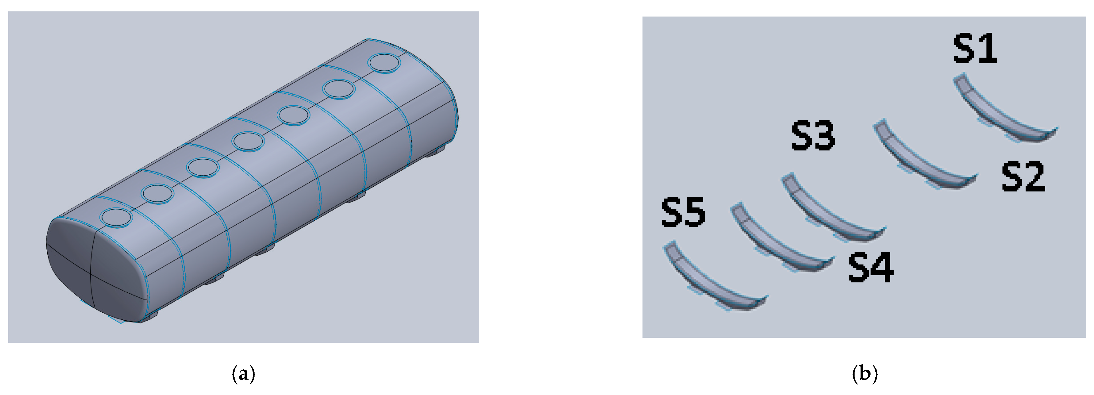
The geometrical model, shown in
Figure 1 consists of the tank and its Ss. The tank consists of the shell walls of the tank, the front and rear shell, six partitions and seven top openings simulating manholes. The Ss (
Figure 1b) of the tank are five (S1–S5) and each one of them consists of the sheet metal that is welded on the shell walls of the tank, the support body and the two mounting plates, one on each side of the support body. The mounting plates are used to bolt the tank to the chassis of the freight vehicle. On each mounting plate, four bolts Μ22 8.8 are used.
The overall dimensions of the tank are presented in
Table 2.
The tank consists of seven compartments, with the first six having length equal to 1.12 m and the last one having length equal to 0.92 m and it has a theoretical capacity of 27,435 lt. In
Figure 2, the placement of the Ss on the tank is presented.
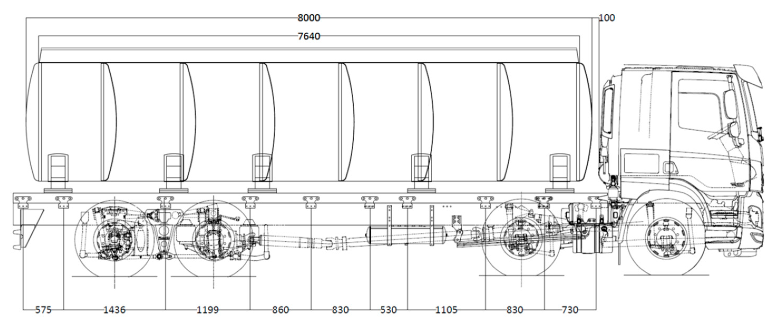
As mentioned above, the tank is mounted on the freight vehicle with five Ss, and the relative positioning of the tank on the freight vehicle is presented in
Figure 3.
The tank and its Ss are built from aluminum alloy sheets, specifically EN 5182 H111. According to Standard 14268:2008 [
21] the minimum tensile strength of EN 5182 H111 equals 280 MPa, and its minimum elongation equals 26%. Given the mechanical characteristics of the aluminum alloy, the geometrical characteristics of the cross-section of the tank and the capacity of each compartment, according to EN13094:2015, the minimum thickness of the aluminum alloy sheet to be used in each component is shown in
Table 3.
In
Table 4, the aluminum alloy sheet thickness that is related to the structural integrity of the tank and is not a strict requirement of EN13094:2015 is presented.
The density of EN5182 H111 is equal to 2660 , which results to a total weight of the structure equal to 1436 kg.
2.2. Finite Element Models of the Tank
Different surface FE models were built in order to decide on feasible designs with different numbers of Ss. The base models differ in the number of Ss and from now on, are referred to as T_iS, where i denotes the number of Ss. The physical and mechanical properties used in all the FE models are summarized in
Table 5.
The design strength was calculated with respect to the yield and the ultimate strength using Equation (1).
All components of the tank are considered to be in fully bonded contact, simulating the corresponding weldments. All contacts are performed surface-to-surface except for those of neighboring shell walls, which are performed edge-to-edge, and the ones simulating the weldments of the manholes to the shell walls that are performed as edge-to-surface.
As far as the weldment design strength is concerned, it was calculated using the weld efficiency factor of 0.8 to the design stress. In
Table 6, the design strength values are presented.
For the meshing the FE size of 50.0 mm was used, and no adaptive sizing was considered. The mesh in all FE models is identical, and
Figure 4 presents the mesh of the FE model T_5S.
The mesh of the tank and the Ss consists of SHELL181 surface FE. SHELL181 are four-nodded FE with three translational and three rotational degrees of freedom at each node, and they employ a five-point integration rule. For the surface-to-surface fully-bonded contacts CONTA174 and TARGE170 surface contact FE were used, while for the edge-to-edge and edge-to-surface fully-bonded contacts, CONTA175 and TARGE170 surface contact FE have been used.
In
Table 7, the number of FE in each FE model, along with the average element quality, is presented. The element quality metric, for shell elements, is based on the ratio of the area of the elements to the sum of the square of the edge lengths, and the value of 1.00 denotes a perfect square or an equilateral triangle.
For the FE analysis, the Sparse Direct solver was used, since it is suitable for structural linear analysis and requires less computational time than Preconditioned Conjugate Gradient solver.
According to EN13094:2015, the shell walls, shell ends and their attachments shall withstand the stress developed due to dynamic, pressure and partial vacuum conditions. This results in seven loading conditions (LC). In order to calculate the mounting of the tank on the freight vehicle, three of them are used, since they cause greater reaction forces. These are:
LC1: The pressure condition, where the applied load was set equal to the pressure created by a column of water equal to twice the depth of the tank.
LC2: Dynamic load, where the applied load was set equal to an acceleration of 2 g acting on the maximum design mass in the direction of travel (-Ζ-axis)
LC3: Dynamic load, where the applied load was set equal to an acceleration of 1 g acting on the maximum design mass at right angles of the travel (X-axis)
In both LC2 and LC3, the total payload of the tank was considered, taking into account the full capacity of the tank and considering that the transported liquid is water with density equal to 1,000,000 .
In
Table 8, the type of load for each LC, its maximum value and the area of application are presented.
Both the pressure and the hydrostatic pressure loads simulated the added mass of the transported substance. For the application of the hydrostatic pressure, FE SURF154 was used. In all LCs, all the degrees of freedom on the nodes of the mounting plates were considered fully fixed.
3. Results
In this section, we present the results of the FE models for different designs, considering the different number of Ss, different positioning and different thickness of sheet material. The main goal was to decide on feasible tank designs with different numbers of Ss. A design was considered feasible when the maximum value of the equivalent von Mises stress (SEQV), as well as the stresses developed on the weldments (Sweld), were lower than and , respectively. Within this framework, four different surface FE models (T_5S_t1, T_4S_t1, T_3S_t1, T2S_t1) were built to investigate the contribution of the number of Ss to the structural integrity of the tank. Moreover, two FE models were built to investigate the alternate positioning of three Ss (T_3SF_t1 & T_3SM_t1). In order to investigate the effect of the thickness of the Ss, three more FE models were built in the case of the three and two supporting structures, taking into consideration the different placement in the case of the triple support (T_3SF_t2, T_3SM_t3, T_3S_t2, T_3SF_t3, T_3SM_t2, T_3S_t3, T_2S_t2 and T_2S_t3). The meshing of the models was identical to the base models. In each investigation, the results of the FE analysis for all the FE models and all LCs under investigation are presented in terms of maximum values and contours SEQV, and Sweld. Furthermore, the reaction forces, leading to conclusions for the bolted connection of the tank on the chassis of the freight vehicle for all feasible designs and all LCs, are presented.
3.1. Investigation of the Reduction of the Number of Supports
In
Table 9, the maximum value of SEQV for each FE in all loading conditions is presented.
In
Table 10, the maximum Sweld for the weldments within the tank is presented for each LC.
In
Table 9 and
Table 10, it is obvious that for LC2, the maximum SEQV value is greater than σd for the models with 3 and 2 Ss and the maximum Sweld value is greater than
for the same models, while for LC3, the maximum SEQV value is greater than
in the model with 2 Ss. In
Figure 5, the SEQV contours are presented for all loading cases for the model T_5S_t1.
The maximum value for LC1 is located on the rear end, for LC2 on the rear Ss (S5) and LC3 in the middle support (S3).
Changing the number of Ss, besides the maximum value of SEQV, also alters the location of the maximum value in LC3. In
Figure 6, the SEQV contour plot for all models is presented for LC3, and the shift of the location from the front Ss to the rear one is obvious.
3.2. Investigation of the Positioning of 3 Ss
In order to obtain a feasible design using 3 Ss, the positioning of the Ss was investigated. Three different positions presented in
Figure 7 were investigated.
The maximum value of SEQV is summarized in
Table 11.
In
Table 12, the component where the maximum value of SEQV appears is shown for all LCs.
In
Table 11 and
Table 12, it is obvious that no feasible design is obtained in the case of the use of 3 Ss, but the T_3S_t1 model results in lower stress values.
3.3. Investigation of the Sheet Material Thickness in the Case of 3 and 2 Ss
Furthermore, the change in thickness of the sheet material is investigated in the case of two and three supports. For the case of three supports, the T_3SR was chosen. Three different thicknesses were used, t1 = 8 mm, t2 = 10 mm and t3 = 12 mm. In
Table 13, the maximum value of SEQV in the case of the use of three supports for all the thicknesses is summarized for all LCs.
In
Table 14, the maximum value of SEQV in the case of the use of two supports for all the thicknesses is summarized for all LCs.
In
Table 13 and
Table 14, it is obvious that when 3 Ss are used, sheet material of a thickness of 10 mm can be used, while in the case of 2 Ss sheet material, a thickness of 12 mm must be used, leading to two feasible designs (T_3S_t2 and T_2S_t3). In
Table 15, the maximum values of contact stress (Sweld) are provided for the feasible designs.
3.4. Reaction Forces in All Feasible Designs
Altering the number of Ss, apart from the structural integrity of the tank construction, also influences the load applied on the bolted connection of the tank construction to the freight vehicle chassis, hence the load distribution between the tank construction and the chassis of the freight vehicle. In order to assess the effect of the number of the Ss on the load distribution the reaction forces developed on the mounting plates are monitored and presented in
Table 16 for all feasible designs for LC1. In LC1 the load is on the Y-axis.
In
Table 17, the reaction forces for all feasible designs for LC2 are presented.
Finally, in
Table 18, the reaction forces for all feasible designs for LC3 are presented.
In
Table 16,
Table 17 and
Table 18, it can be noted that the larger reaction forces are developed in LC2 on the X-axis, loading the bolted connections in shear.
4. Discussion
The tank for the road transport of flammable liquids used as a case study (T_5S_t1) in this work was designed according to the aforementioned standards, and because of its cross-sectional geometry and the compartment capacity, was constructed using reduced thickness for the aluminum alloy sheets, which is presented in
Table 3. Moreover, the thickness of the sheet material used for the manufacturing of the Ss is shown in
Table 4. In order to get a feasible design with 3 and 2 Ss, the thickness of the sheet material used for the support body increased to 10 mm and 12 mm, respectively. In
Figure 8, the weight of all feasible designs is presented, and as expected, reducing the number of Ss leads to reduced weight even if a thicker sheet material is used.
In
Table 9,
Table 13 and
Table 14, the maximum SEQV values (
) per LC for all feasible designs were presented. In order to comparatively assess the feasible designs in terms of structural integrity, the material usage (MU) index is defined as it is shown in Equation (2).
In
Table 19, the MU index for each feasible design in all LCs is provided.
In
Table 19, it is obvious that the value of MU index lies between 0.49 to 0.67. The LC that is more susceptible to the change of the number of Ss is LC3, which overall presents the lower MU values.
A similar index can be also defined for the weldments, as shown in Equation (3). The values of the contact stress developed on the area of the weldments are presented in
Table 10 and
Table 15.
In
Table 20, the
values are presented for all feasible designs and LCs. The value of the MU index lies between 0.18 to 0.74. The LC that is more susceptible to the change of the number of Ss is LC3, and the LC with the highest value of
is LC2.
4.1. Effect of the Number of Ss on the Dynamic Behavior of the Tank
In order to investigate the effect of the number of Ss on the dynamic behavior of the tank construction, modal analysis was performed in all the feasible designs. During modal analysis, it was shown that the number of Ss affects the value of the first three eigen frequencies, which are summarized in
Table 21.
In
Figure 9, the eigenshapes for these eigenfrequencies are presented in the feasible design with five Ss.
In
Table 21, it is noted that the reduction of the number of Ss leads to a reduction of the value of the first three eigenfrequencies. However, the change in the number of Ss affects neither the eigen shape nor the values of maximum displacement that are presented in
Figure 9 for the case of five Ss.
4.2. Effect of the Number of the Ss on the Load Distribution to the Vehicle Chassis
In order to assess the effect of the number of Ss on the distribution of the load of the tank to the chassis of the freight vehicle, firstly, the reaction forces developed on the mounting plates should be reviewed. In
Table 16,
Table 17 and
Table 18, it is obvious that the highest values of the reaction forces appear in LC2, which simulates the braking of the freight vehicle. Furthermore, in all LCs, the rear Ss receives less load than the front one. In order to assess this in further detail, the effect of the number of the Ss on the distribution of the load to the mounting plates the % of the load received by each Ss is presented in
Table 22 for all feasible designs for LC1. Even in the case of five Ss, the ones that receive the higher % of the load are the front (S1) and the rear (S5) Ss.
In
Table 23, the percentage of total loading for all feasible designs for LC2 is presented. In this loading case, all the Ss participate equally in the mounting of the tank to the chassis.
Finally, in
Table 24, the percentage of total loading for all feasible designs for LC2 is presented. In this LC, the intermediate Ss are highly loaded. In the case of 2 Ss (T_2S_t3), the load is equally distributed between the two Ss.
In order to qualitatively assess the axle load-sharing on the freight vehicle, a simplified surface FE model simulating the beams of the chassis has been developed (
Figure 10).
On the top of the beam, the five mounting plates of the tank were modeled, while on the bottom of the beam, the four mounting plates corresponding to the mounting of the axles on the chassis of the freight vehicle, as they are presented in
Figure 3, are also modeled. The model consists of 906 FE and 972 nodes. All mounting plates were considered fully bonded on the beam. Structural steel was considered as the material of the chassis and the bottom plates simulating the axle mounting and aluminum alloy for the top ones simulating the tank mounting.
In
Figure 11, the loading conditions in the case of five Ss for all LCs are presented. On the top plates, the reaction forces provided in
Table 16,
Table 17 and
Table 18 were applied, simulating the tank LCs and the reduction of the Ss. The translational as well as the rotational degrees of freedom of the nodes on the bottom plates, were fully fixed.
The reaction forces on the four bottom plates, where the mounting of the axles to the chassis are, were monitored. In order to assess the effect of the number of the Ss % of the total reaction force received by each supporting structure, it was monitored and presented in
Table 25 for all feasible designs for LC1 on the Y-axis.
In
Table 26 the percentage of total loading for all feasible designs for LC2 on the Z-axis is presented.
Finally, in
Table 27, the percentage of total loading for all feasible designs for LC2 is presented.
In LC1 (
Table 25) and LC3 (
Table 27), the axle with the highest load is the fourth one, while in LC2 (
Table 26), the axle with the highest load is the third one. Furthermore, in LC2 and LC3, the reduction of the number of Ss of the tank causes a shift of load from the two intermediate axles to the first and fourth one, as is shown in
Figure 12.
5. Conclusions
In the present paper, the reduction of the number of Ss of a tank transporting flammable liquid was studied computationally using the FE method. The effect of the number of Ss on the overall performance of the tank and the freight vehicle was investigated in terms of structural integrity, dynamic behavior and load distribution to the axles of the freight vehicle. The aforementioned methodology can be used in any tank vehicle with different cross-sectional geometry, length and compartmentalization in order to provide a lighter and more efficient tank vehicle.
For the performed computational investigation, a real-life tank for the transport of flammable liquids with a maximum capacity equal to 27 tn, five Ss and mounted on a four-axle freight vehicle with a maximum permissible laden mass of 35 tn was used. A total of fourteen FE models with different numbers of Ss, ranging from five to two, different Ss positioning and different thickness of the sheet material used for the manufacturing of the support body, ranging from 8 mm to 10 mm, ware built. In all the FE models, the maximum values of SEQV and Sweld were lower than and , but as a feasible design, was defined as a design having maximum values of SEQV and Sweld lower than and . In all feasible designs, although the increase in the thickness of the sheet material improved the structural integrity of the tank, the positioning of the Ss did not influence it. The reduction of the number of Ss from five to two leads to a reduction of the tank tare weight by 9.6%, proving that the Ss contribute gravely to the tare weight of the tank. In order to find the most demanding load case and the most efficient design in terms of structural integrity, the MU index was defined. The LC with the highest MU is LC2 and the design with the highest MU in all the LCs is T_2S_t3, meaning that it is the most efficient in terms of structural integrity.
As far as the dynamic behavior of the tank is concerned, it was found that the reduction in the number of Ss influences the first three eigenfrequencies, thereby reducing them (
Table 21), but does not affect the corresponding eigen shapes. The lowest eigenfrequency is met in T_2S_t3 (30 Hz) which is still high enough, considering that the eigenfrequencies of the axle of a heavy vehicle are in the range of 10–15 Hz [
22], the eigenfrequencies of the sprung mass are in the range of 1–4 Hz [
23] and the eigenfrequencies of the liquid sloshing are less than 6 Hz for fully-loaded tanks [
24].
When examining the load distribution to the Ss, it is obvious that the usage of fewer Ss leads to smoother load distribution in all LC. When comparing the design with two Ss to that with 5 Ss in terms of the magnitude of the supported load in LC1, it is obvious that the load distribution remains roughly the same for both Ss, with a slight decrease in S1 and a slight increase in S5 (less than 5%); additionally, in LC2, the load supported by S1 and S5 increases by almost 30% and in LC3 by almost 35%. This enforces the change of the bolts used in the bolted connection of the tank on the chassis of the freight vehicle in terms of geometrical and mechanical properties, i.e., their diameter and grade. Still, the reduction of the number of Ss from five to two affects the number of the needed bolts. In more detail, a tank with five Ss needs 40 bolts while one with two Ss needs 16 bolts, making the mounting of the tank on the freight vehicle and the maintenance of the bolted connections quicker in terms of time.
Finally, in reviewing the load distribution to the axles of the freight vehicle, retrieved by the simplified qualitative FE model, it is obvious that it is not gravely affected by the reduction of the number of Ss. Still, in LC2 and LC3, a transfer of load from axles 2 & 3 to axels 1 & 4 can be observed.
Using the FE method, the reduction of the number of the Ss on a tank used for the transport of flammable liquids has been thoroughly investigated. The outcome of this investigation can be used as a guideline for the tank design and construction, suggesting that the number of supports should be the minimum that can result in a feasible design. Using fewer Ss can maximize the payload of the tank and minimize the time needed for each manufacturing and maintenance.


