Abstract
Due to the simple structure, low inertia and the ability to operate for a long time under high-speed and high-temperature conditions, the induction motor is widely used in high-speed applications. Aiming at the most prominent loss and stress problems in high-speed induction motors, the use of low loss material and the choice of a reliable rotor structure are effective optimized methods. In this paper, the electromagnetic loss, stator temperature distribution and performance parameters of high-speed induction motor are analyzed with stator cores of different materials. In addition, for the different rotor structures, the mechanical stress is compared. Furthermore, the comparison and analysis are used to improve the motor performance and provide a reference for prototype development. A performance test of the prototype is conducted, which proves the validity of the study in this paper.
1. Introduction
With the continuous innovation of industrial technology and the actual needs of production and application, high-speed motors are the research hotspot in motor field. Compared with the conventional motor, the high-speed motor has high power density, high transmission efficiency, low noise and fast dynamic response, and therefore is generally used in air compressors, CNC engraving machines and other equipment [1,2,3,4,5].
The high-speed induction motor is the most widely used in the field of high-speed motors [6]. However, the loss of the motor is much greater than that of the conventional one due to the high frequency and loss density; while the centrifugal force of the motor rotor will increase significantly when the speed is over 10,000 rpm, resulting in rotor strength problems. Thus, a reasonable electromagnetic design to reduce loss and improve motor mechanical performance is the key point in the design of high-speed induction motors.
In recent decades, the usage of the amorphous alloy (AA) as the stator core material is attracting great attention [7]. An analytical model of electromagnetic vibration and noise for a high-speed AA permanent magnet synchronous motor was presented in [8]. A new loss factor correction model of the amorphous alloy core was proposed to analyze the influence of the processing and core size on the loss in [9]. Much research and many studies have shown that using AA material can effectively reduce motor loss, thus improve the overall efficiency of the motor [10,11,12].
The effect of different rotor structures on motor performance was studied in previous research [13,14,15,16]. The rotor structure of the high-speed motor is usually slender. With a small rotor radius, it is easier for the entire rotor system to reach the critical speed, causing bending resonance of the rotor. Different rotor structures have different effects on the performance of high-speed induction motors. In the design process, it is necessary to select a suitable rotor structure scheme according to the actual situation.
In this paper, the electromagnetic loss and the motor performance of the high-speed induction motor with amorphous alloy and silicon steel core are compared under the same working conditions. In addition, the characteristics and the mechanical stress of different rotor structures are studied to obtain a reliable rotor mechanical structure. Thereafter, an optimization design is identified based on the study and a prototype is made for verification research.
2. Loss Analysis and Material Comparison
2.1. Loss Analysis
Loss is a decisive factor affecting the efficiency of the motor. To reach a certain efficiency index, it is particularly important to accurately calculate the motor loss and effectively control the temperature rise. The loss of high-speed induction motor mainly includes copper loss and core loss.
2.1.1. Copper Loss
In the traditional way, the copper loss of each part can be calculated separately by multiplying the square of the current and the resistance , and then superimposed to get the total copper loss :
Given full consideration to the characteristics of winding distribution and the influence of harmonic currents caused by saturation and other factors, copper loss calculation based on finite element analysis is as follow [17]:
where is the copper loss of the stator winding, is the winding resistance per phase, is the harmonic current and k is the odd harmonic current; is the copper loss of the rotor bar, is the equivalent length of the bar, is the unit area of the bar, is the current density and is the conductivity.
2.1.2. Core Loss
The core loss can be divided into hysteresis loss, eddy current loss, and excess loss. The hysteresis loss is a lag in response to changing forces based on energy loss resulting from internal friction, which is caused by the phenomenon of hysteresis that occurs in the alternating magnetization process of ferromagnetic materials. The hysteresis loop as shown in Figure 1 is often applied to describe and calculate the hysteresis loss. In one magnetization period T, the hysteresis loss can be defined as:
where f is the frequency, V is the volume, is the area of the hysteresis loop. Hence, the hysteresis loss is proportional to the hysteresis loop area for ferromagnetic materials.

Figure 1.
Hysteresis Loop of Ferromagnetic Materials.
Normally, can be approximately written as [18]:
where is the calculation coefficient of hysteresis loss, is the maximum magnetic flux density, is the coefficient.
Due to the excellent magnetic conductivity, ferromagnetic materials in an alternating magnetic field generate induced electromotive force and induced current, leading to the power loss on the equivalent resistance of the circuit, called the eddy current loss. According to the law of electromagnetic induction, the induced electromotive force of a piece of silicon steel sheet with thickness d, height h and length l in Figure 2 can be written as:
where K is the induced electromotive force proportional constant, x is the distance between the eddy current loop and the symmetry axis of the silicon steel sheet. The differentiation of the equivalent resistance of the eddy current loop can be described as:
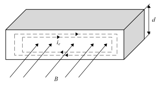
Figure 2.
Cause of the Eddy Current Loss.
From the above equations, the differential of the eddy current loss in the eddy current loop can be obtained as:
By integrating the both sides, the eddy current loss in the silicon steel sheet can be obtained as:
The cause and process of excess loss are relatively complicated. After actual calculation and verification, it can be written as:
where is the excess loss factor.
In the classical constant coefficient trinomial model proposed by the Italian scholar Bertotti [19,20,21], the total core loss can be written as:
where is the hysteresis loss factor, is the classical eddy current loss, is the classical eddy current loss factor.
In addition to the material properties, there is also a difference in the price between 1K101 and 20JNEH1200. The price of amorphous alloy 1K101 is 45 CNY/kg, while that of silicon steel 20JNEH1200 is 36 CNY/kg.
2.2. Material Characteristics Comparison
The material properties comparison between amorphous alloy 1K101 and silicon steel 20JNEH1200 are shown in Table 1. By Comparing, it can be seen that AA has higher resistivity, thinner thickness and lower coercivity.

Table 1.
Material Properties Comparison.
Figure 3 and Figure 4 show the B–H curves of the above two. The inflection point of the magnetic density of 1K101 is lower than that of 20JNEH1200, which means that the saturation magnetic density of the former is smaller.
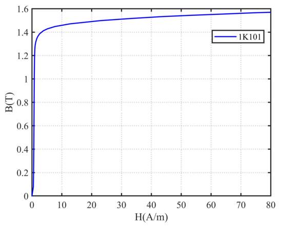
Figure 3.
B-H Curves of 1K101.
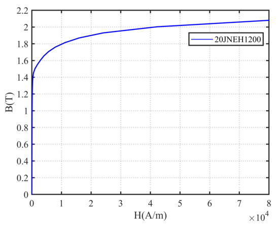
Figure 4.
B-H Curves of 20JNEH1200.
2.3. Comparison of Motor Loss and Performance with Stator Core of Different Materials
To calculate and analyze the motor loss and performance with stator core of different materials, finite element simulation is established in this section. The main parameters of high-speed induction motor are shown in Table 2.
Table 2.
Material Properties Comparison.
The finite element simulation is carried out on Ansys Maxwell 2D software, which is a large-scale general finite element analysis software developed by American ANSYS Company, Canonsburg, PA, USA. Maxwell 2D is a powerful and easy-to-use two-dimensional electromagnetic field finite element numerical calculation and analysis software. It is based on Maxwell’s differential equations and uses a finite element discrete form to convert electromagnetic field calculations into a huge matrix solution. As is known to all, when the motor is in motion, the magnetic field, force and speed and other physical quantities will change with time, and the changes are mostly nonlinear. Therefore, transient analysis is adopted to get reliable and accurate results. The 2D Transient magnetic model of the motor and its skin-depth mesh structure are shown in Figure 5. The model includes the stator, rotor, stator windings, rotor bars, and the shaft part of the motor.
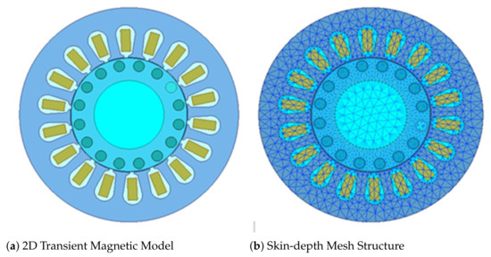
Figure 5.
Maxwell 2D Transient Magnetic Model and Skin-depth Mesh Structure.
The above two materials are taken as the stator core material respectively. According to the material data sheets of 1K101 and 20JNEH1200 provided by the manufacturer, the core loss calculation coefficients in Equation (12) of the two materials are shown respectively:
, , ;
, , . The comparison of the copper loss are shown in Figure 6 and Figure 7, while that of the core loss is shown in Figure 8. The exact values of the motor losses are indicated in Table 3.
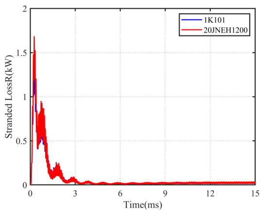
Figure 6.
Comparison of the Copper Loss in the Stator Winding.
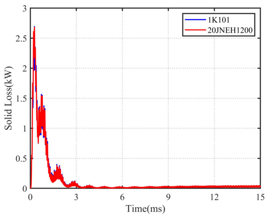
Figure 7.
Comparison of the Copper Loss in the Rotor Bar.
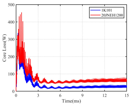
Figure 8.
Comparison of the Core Loss.
Table 3.
Comparison of the Motor Losses.
In steady state, the average core loss of the silicon steel motor is 62.34 W, while that of the AA motor is 24.12 W, significantly reduced by about 61%. However, the average copper loss is almost the same. As can be seen in Figure 9 and Figure 10, the stator temperature of the AA motor is much lower than that of the silicon steel motor. Table 4 shows the performance parameters at the rated speed of the two motors. Compared with the silicon steel motor, the total loss of the AA motor is reduced by 81.2 W, the efficiency is increased by 3.2%, the power factor is increased by 0.016, and the output torque is increased by 0.02 N·m. All the results demonstrate the advantages of the amorphous alloy as the stator core material.
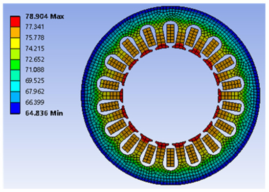
Figure 9.
Stator Temperature Distribution of AA Motor.
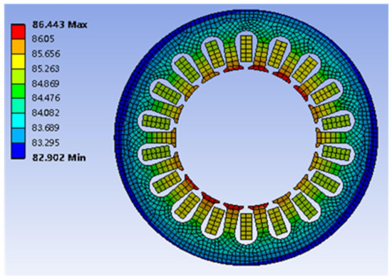
Figure 10.
Stator Temperature Distribution of the Silicon Steel Motor.
Table 4.
Comparison of the Performance Parameters at Rated Speed.
3. Mechanical Stress Analysis and Comparison of Rotor Structures
3.1. Types of Rotor Structures
The laminated rotor and the solid rotor are usually adopted in a high-speed induction motor. The laminated rotor usually has a closed-slot, mainly including the round, the drop-shaped, and the parallel three types, as shown in Figure 11. With a low cost and a simple manufacturing process, the rotor bar of the round slot is small, which can reduce the influence of the mechanical stress and ensure the mechanical strength of the rotor in high-speed operation. However, the small shape makes a small slot pitch, increases the magnetic flux density of the rotor teeth and the current density of the rotor bar, consequently leads to an increase of the copper loss. The drop-shaped and parallel slot are the improvement over the round slot, but have a weakness on the mechanical strength.
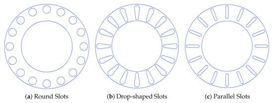
Figure 11.
Slot Types of the Laminated Rotor.
At present, the topological structure of solid rotors is mainly divided into smooth solid rotors, slotted solid rotors, copper-plated solid rotors, and squirrel cage solid rotors [22]. The smooth solid rotor is of high mechanical strength, resistance and leakage inductance, but is easy to cause large eddy current loss. To reduce that loss, the slitted solid rotor appears. The axially slitted solid rotor can control the direction of the eddy current on the rotor surface to increase the output torque of the motor, whereas the radially slitted solid rotor can increase the length of the eddy current loop to reduce the eddy current loss. However, the processing technology of the slitted solid rotor is relatively complicated. Generally, the coated solid rotor (the solid rotor coated with a copper layer) is more used. As for the caged rotor, it has the worst torque-speed characteristic with low pull-out torque, fast-changing rotor speed with the load and a weak structure [13].
3.2. Mechanical Stress Analysis
For high-speed motors, the maximum mechanical stress that the rotor can withstand limits the output power and maximum speed, which places a higher demand on the rotor structure [23,24]. The maximum mechanical stress caused by the centrifugal force of the rotor is proportional to the square of the angular velocity :
where for the smooth and uniform cylinder, ; for the cylinder with small holes, ; for the thin hollow cylinder, . R is the rotor radius, is the material density, is the Poisson’s ratio.
Equation (13) is used to judge the distribution of the stress rather than to calculate. Usually, the maximum point of stress is in the center of the rotor or at the welding point of the rotor end ring. In these areas, the stress value cannot exceed the ultimate strength of the material.
The centrifugal force applied to an object with a mass m rotating at a specific linear velocity at the radius of r can be written as:
According to Equations (13) and (14), the maximum stress caused by the centrifugal force is proportional to the square of the angular velocity.
3.3. Mechanical Stress Comparison of Different Rotor Structures
In this section, the motor rotor stress of the laminated rotor and the smooth solid rotor is compared. To maximize the mechanical strength and increase the starting torque, the round slot with two 5 mm end rings is adopted in the laminated rotor structure. The results are shown in Figure 12 and Figure 13. At the rated speed of 59,000 rpm, the maximum stress of the latter appears at the inner surface, which is 16.042 Mpa, while that of the former is significantly increased due to the end rings, which is 100.54 Mpa. However, both of them are less than the yield strength of the materials.
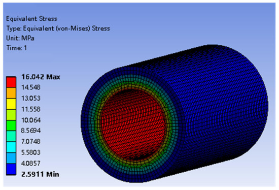
Figure 12.
Mechanical Stress of the Smooth Solid Rotor.
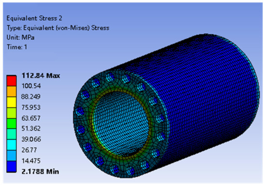
Figure 13.
Mechanical Stress of the Laminated Rotor.
According to Figure 14, the maximum stress of the laminated rotor at the maximum speed is 415.93 Mpa, less than the usual yield strength of the material. Although the smooth solid rotor motor has better mechanical performance, the laminated rotor motor can effectively reduce the eddy current loss, thereby has a higher efficiency [25,26].
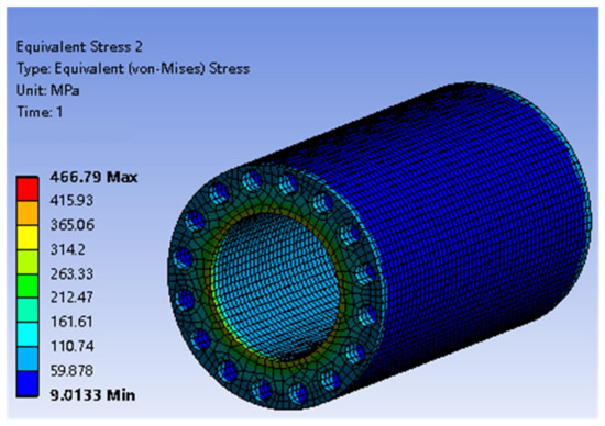
Figure 14.
Maximum Mechanical Stress of the Laminated Rotor.
4. Prototyping and Performance Test
According to the simulation results, the round slot laminated rotor is applied to the high-speed amorphous alloy induction motor proposed. Based on the above finite element calculation of the motor, the SVPWM is used for the voltage control and the MTPA control strategy is adopted in this section to get an efficiency MAP diagram of the entire process of motor operation. The efficiency MAP diagram plays an important role in the evaluation and testing of the motor efficiency. It can assist the designer to find the most efficient, low-consumption, and high-endurance solution, which can improve the overall performance of the electric vehicle.
ANSYS Maxwell Toolkit is used to get the motor efficiency MAP diagram. In the simulation, the maximum speed is set as 60,000 rpm. When the motor speed is below the rated speed, the amplitude and the phase angle of the stator current, and the speed are scanned parametrically to simulate working conditions at different speeds and torques; when the speed is over the rated speed, the current power angle changes constantly to simulate different direct-axis demagnetization currents, and the maximum input voltage is taken as the constraint condition to obtain the output characteristics of the motor in the field weakening work area. After obtaining most output and loss data in operating area, the efficiency of the motor under different working conditions is calculated. The efficiency MAP diagram of the motor is obtained in Figure 15.
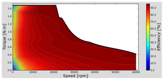
Figure 15.
Efficiency MAP Diagram of the Motor.
The motor efficiency MAP diagram reflects the distribution of motor efficiency at different speeds and torques. It can be seen that when the motor is at low torque and low speed, the efficiency is low; and as the speed increases, the efficiency also gradually increases. Moreover, the efficiency is the largest near the rated operating point of the motor, and the maximum efficiency is about 95%. The motor can maintain a high efficiency of more than 90% in the speed range of 10,000–60,000 rpm.
The prototype of the motor is shown in Figure 16. The 0.025 mm amorphous alloy 1K101 strip is laminated to the required thickness, then annealed, dipped, and solidified to form an amorphous alloy block, and finally the amorphous alloy block is processed into the required motor stator core by a wire cutting process. The copper conductor bars of the winding are welded together with end rings. When starting, the end rings will be severely saturated, so the rotor can obtain a high resistance. Additionally, the rotor core is laminated with copper-clad laminates, which can make a smooth surface to reduce wind friction loss.
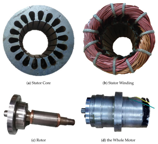
Figure 16.
Prototype of the Motor.
To verify the performance of high-speed amorphous alloy induction motor and prove the validity of the study in this paper, a performance test is conducted. Figure 17 shows the test bench of the motor prototype, mainly including the dynamometer and its controller, driver system, and power supplies. The WH6000 motor dynamometer controller adopts digital synchronous sampling technology and microcomputer technology, and it can accurately measure the speed, torque, power, and efficiency of the motor dynamometer. The performance test was conducted up to 60,000 rpm.
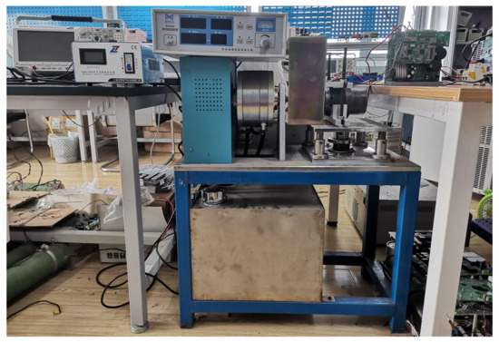
Figure 17.
Test Bench of Prototype.
The comparison of the motor performance between simulation and measurement are shown in Figure 18, Figure 19 and Figure 20.
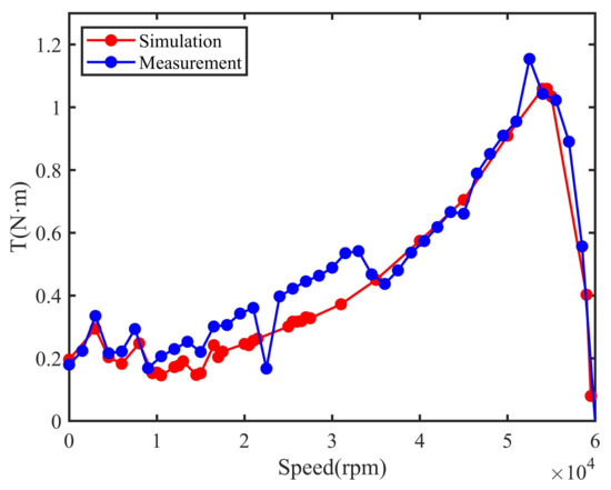
Figure 18.
Comparison of Speed-Torque Curve.
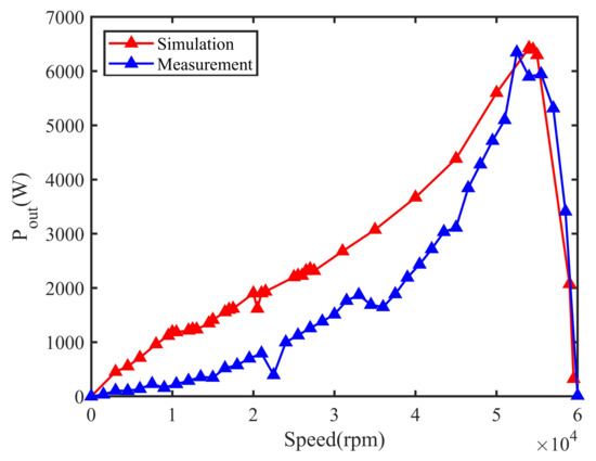
Figure 19.
Comparison of Speed-Output Power Curve.
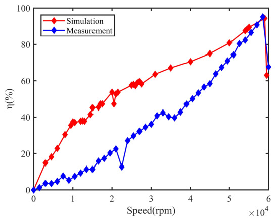
Figure 20.
Comparison of Speed-Efficiency Curve.
The test data of measurement and simulation are shown in Table A1 and Table A2 of Appendix A. From the above curves, it can be seen that there is a certain gap between the prototype test values and the simulation values of the same performance parameter. The simulation values of the motor torque, output power, and efficiency are significantly better than the actual measured values. However, the trends of the curves are quite consistent, and the errors are within a reasonable range. According to the results, the high-speed amorphous alloy induction motor has a good performance.
5. Conclusions
In this paper, the composition and generation mechanism of electromagnetic loss in the high-speed induction motor are studied, and the calculation methods are given. Moreover, the motor loss with different materials is calculated and compared based on finite element simulation. Furthermore, the characteristics and the mechanical stress of different rotor structures are studied and analyzed. Based on the simulation results, a reliable rotor mechanical structure is obtained and a high-speed amorphous alloy induction motor is made. Finally, the results of the prototype performance test verify the performance of high-speed amorphous alloy induction motor and prove the validity of the study in this paper.
Author Contributions
Conceptualization, Z.F.; investigation, H.Y.; methodology, J.X., K.X. and Y.Q.; resources, Z.F., J.X. and K.X.; writing-original draft, S.R. and H.W.; writing-review and editing, H.Y., Y.Q., H.W. and S.R. All authors have read and agreed to the published version of the manuscript.
Funding
This research received no external funding.
Institutional Review Board Statement
Not applicable.
Informed Consent Statement
Not applicable.
Data Availability Statement
Not applicable.
Acknowledgments
The authors would like to thank the members of Key Laboratory of Marine Intelligent Equipment and System (Ministry of Education) and China Ship Development and Design Center for their help in this study.
Conflicts of Interest
The authors declare no conflict of interest.
Abbreviations
The following abbreviations are used in this manuscript:
| CNC | Computer Numerical Control |
| AA | Amorphous Alloy |
| CNY | Chinese Yuan |
| SVPWM | Space Vector Pulse Width Modulation |
| MTPA | Maximum Torque Per Ampere |
Appendix A
Table A1.
Prototype Performance Test Data.
Table A1.
Prototype Performance Test Data.
| Number | Speed | Torque | Input Power | Output Power | Efficiency |
|---|---|---|---|---|---|
| (rpm) | (N·m) | (W) | (W) | (%) | |
| 1 | 0 | 0.196019 | 2997.55 | 0 | 0 |
| 2 | 3000 | 0.294189 | 3067.07 | 453.93 | 14.8 |
| 3 | 4500 | 0.203523 | 3066.85 | 555.64 | 18.12 |
| 4 | 6000 | 0.182651 | 3127.15 | 712.76 | 22.79 |
| 5 | 8000 | 0.247552 | 3162.71 | 962.43 | 30.43 |
| 6 | 9500 | 0.152614 | 3145.89 | 1119.08 | 35.57 |
| 7 | 10,000 | 0.154452 | 3167.13 | 1185.33 | 37.43 |
| 8 | 10,500 | 0.145520 | 3193.01 | 1184.60 | 37.10 |
| 9 | 12,000 | 0.172023 | 3219.63 | 1216.31 | 37.78 |
| 10 | 12,500 | 0.176870 | 3254.01 | 1236.48 | 38.00 |
| 11 | 13,000 | 0.190634 | 3269.80 | 1235.60 | 37.79 |
| 12 | 14,500 | 0.147138 | 3248.90 | 1348.29 | 41.50 |
| 13 | 15,000 | 0.152417 | 3168.05 | 1413.40 | 45.18 |
| 14 | 16,500 | 0.241848 | 3417.87 | 1554.51 | 45.48 |
| 15 | 17,000 | 0.203657 | 3386.30 | 1599.85 | 47.24 |
| 16 | 17,500 | 0.221533 | 3425.06 | 1618.80 | 47.26 |
| 17 | 20,000 | 0.245917 | 3541.61 | 1901.36 | 53.69 |
| 18 | 20,500 | 0.241755 | 3425.06 | 1618.68 | 47.26 |
| 19 | 21,000 | 0.255911 | 3612.02 | 1903.25 | 52.69 |
| 20 | 21,500 | 0.262509 | 3604.54 | 1934.29 | 53.66 |
| 21 | 25,000 | 0.301267 | 3826.45 | 2201.47 | 57.53 |
| 22 | 25,500 | 0.316899 | 3885.19 | 2227.16 | 58.01 |
| 23 | 26,000 | 0.316899 | 3885.19 | 2227.16 | 57.32 |
| 24 | 26,500 | 0.318622 | 3927.73 | 2313.31 | 58.90 |
| 25 | 27,000 | 0.330644 | 3945.88 | 2348.45 | 59.52 |
| 26 | 27,500 | 0.327650 | 3975.60 | 2315.79 | 58.25 |
| 27 | 31,000 | 0.372236 | 4209.22 | 2677.48 | 63.61 |
| 28 | 35,000 | 0.449925 | 4583.75 | 3074.66 | 67.08 |
| 29 | 40,000 | 0.574427 | 5203.65 | 3670.32 | 70.53 |
| 30 | 45,000 | 0.704867 | 5848.09 | 4384.27 | 74.97 |
| 31 | 50,000 | 0.909315 | 6934.04 | 5600.73 | 80.77 |
| 32 | 54,000 | 1.058910 | 7343.48 | 6427.44 | 87.53 |
| 33 | 54,500 | 1.058910 | 7231.88 | 6397.59 | 88.46 |
| 34 | 55,000 | 1.034429 | 7042.91 | 6297.01 | 89.41 |
| 35 | 59,000 | 0.402674 | 2197.68 | 2074.34 | 94.39 |
| 36 | 59,500 | 0.079928 | 513.41 | 323.78 | 63.06 |
Table A2.
Simulation Data.
Table A2.
Simulation Data.
| Number | Speed (rpm) | Torque (N·m) | Input Power (W) | Output Power (W) | Efficiency (%) |
|---|---|---|---|---|---|
| 1 | 0 | 0.179860 | 3808.74 | 0 | 0 |
| 2 | 1500 | 0.223726 | 3867.88 | 35.14 | 1.24 |
| 3 | 3000 | 0.335093 | 3911.09 | 105.27 | 3.65 |
| 4 | 4500 | 0.216263 | 3935.97 | 101.91 | 3.52 |
| 5 | 6000 | 0.221909 | 3947.89 | 139.43 | 4.75 |
| 6 | 7500 | 0.293345 | 3879.64 | 230.39 | 7.67 |
| 7 | 9000 | 0.168453 | 3934.51 | 158.76 | 5.41 |
| 8 | 10,500 | 0.206529 | 4015.59 | 227.09 | 7.50 |
| 9 | 12,000 | 0.229392 | 4074.94 | 288.26 | 9.35 |
| 10 | 13,500 | 0.252820 | 4122.88 | 357.42 | 11.34 |
| 11 | 15,000 | 0.220382 | 3991.31 | 346.18 | 11.35 |
| 12 | 16,500 | 0.301273 | 4229.42 | 520.56 | 15.79 |
| 13 | 18,000 | 0.306130 | 4305.29 | 577.04 | 17.29 |
| 14 | 19,500 | 0.342538 | 4349.30 | 699.48 | 20.28 |
| 15 | 21,000 | 0.360786 | 4412.97 | 793.41 | 22.50 |
| 16 | 22,500 | 0.167253 | 4404.97 | 394.08 | 12.67 |
| 17 | 24,000 | 0.397220 | 4550.06 | 998.32 | 27.04 |
| 18 | 25,500 | 0.422175 | 4651.79 | 1127.36 | 29.69 |
| 19 | 27,000 | 0.445176 | 4719.14 | 1258.71 | 32.24 |
| 20 | 28,500 | 0.463302 | 4802.57 | 1382.73 | 34.53 |
| 21 | 30,000 | 2.228737 | 3829.72 | 7001.78 | 72.11 |
| 22 | 31,500 | 0.535167 | 5001.22 | 1765.34 | 40.82 |
| 23 | 33,000 | 0.541701 | 5115.64 | 1871.99 | 42.39 |
| 24 | 34,500 | 0.467698 | 5289.97 | 1689.71 | 40.29 |
| 25 | 36,000 | 0.437137 | 5412.87 | 1647.97 | 39.71 |
| 26 | 37,500 | 0.480183 | 5471.30 | 1885.67 | 42.85 |
| 27 | 39,000 | 0.536936 | 5708.00 | 2192.89 | 47.16 |
| 28 | 40,500 | 0.573760 | 5881.07 | 2433.40 | 50.10 |
| 29 | 42,000 | 0.618045 | 6074.37 | 2718.31 | 53.28 |
| 30 | 43,500 | 0.666158 | 6297.36 | 3034.56 | 56.58 |
| 31 | 45,000 | 0.660873 | 6563.94 | 3114.29 | 58.42 |
| 32 | 46,500 | 0.789207 | 6778.41 | 3843.02 | 63.82 |
| 33 | 48,000 | 0.851525 | 7031.28 | 4280.23 | 67.41 |
| 34 | 49,500 | 0.909824 | 7266.67 | 4716.19 | 70.93 |
| 35 | 51,000 | 0.954736 | 7482.60 | 5098.97 | 74.29 |
| 36 | 52,500 | 1.154322 | 7758.21 | 6346.21 | 80.39 |
| 37 | 54,000 | 1.042989 | 7506.11 | 5897.96 | 82.35 |
| 38 | 55,500 | 1.022872 | 7044.18 | 5944.87 | 86.52 |
| 39 | 57,000 | 0.890487 | 5908.61 | 5315.34 | 90.76 |
| 40 | 58,500 | 0.556827 | 3559.67 | 3411.18 | 95.17 |
| 41 | 60,000 | −0.003362 | 21.13 | 12.78 | 67.65 |
References
- Jung, E.; Yoo, H.; Sul, S.K.; Choi, H.S.; Choi, Y.Y. Nine-Phase Permanent Magnet Motor Drive System for Ultra High-Speed Elevator. In Proceedings of the 2009 IEEE Energy Conversion Congress and Exposition, San Jose, CA, USA, 20–24 September 2009; pp. 1841–1846. [Google Scholar]
- Wen, J.S.; Wang, C.H.; Chang, Y.D.; Teng, C.C. Intelligent control of high-speed sensorless brushless DC motor for intelligent automobiles. In Proceedings of the 2008 IEEE International Conference on Systems, Man and Cybernetics, Singapore, 12–15 October 2008; pp. 3394–3398. [Google Scholar]
- Pyrhonen, J.; Nerg, J.; Kurronen, P.; Lauber, U. High-Speed High-Output Solid-Rotor Induction-Motor Technology for Gas Compression. IEEE Trans. Ind. Electron. 2010, 57, 272–280. [Google Scholar] [CrossRef]
- Liu, X.; Du, J.; Liang, D. Analysis and speed ripple mitigation of a space vector pulse width modulation-based permanent magnet synchronous motor with a particle swarm optimization algorithm. Energies 2016, 9, 923. [Google Scholar] [CrossRef]
- Yu, Y.N.; Liang, D.L.; Liu, X. Optimal Design of the Rotor Structure of a HSPMSM Based on Analytic Calculation of Eddy Current Losses. Energies 2017, 10, 551. [Google Scholar] [CrossRef]
- Tenconi, A.; Vaschetto, S.; Vigliani, A. Electrical Machines for High-Speed Applications: Design Considerations and Tradeoffs. IEEE Trans. Ind. Electron. 2014, 61, 3022–3029. [Google Scholar] [CrossRef]
- Fan, T.; Li, Q.; Wen, X. Development of a High Power Density Motor Made of Amorphous Alloy Cores. IEEE Trans. Ind. Electron. 2014, 61, 4510–4518. [Google Scholar] [CrossRef]
- Chen, P.; Chen, J.; Liao, Y.; Zhang, C.; Du, J. Vibration and Noise of High Speed Amorphous Alloy Permanent Magnet Synchronous Motor. In Proceedings of the 2018 21st International Conference on Electrical Machines and Systems (ICEMS), Jeju, Korea, 7–10 October 2018; pp. 318–322. [Google Scholar]
- Chai, F.; Li, Z.; Chen, L.; Pei, Y. Effect of Cutting and Slot Opening on Amorphous Alloy Core for High-Speed Switched Reluctance Motor. IEEE Trans. Magn. 2021, 57, 1–5. [Google Scholar] [CrossRef]
- Okamoto, S.; Denis, N.; Kato, Y.; Ieki, M.; Fujisaki, K. Core Loss Reduction of an Interior Permanent-Magnet Synchronous Motor Using Amorphous Stator Core. IEEE Trans. Ind. Appl. 2016, 52, 2261–2268. [Google Scholar] [CrossRef]
- Kolano, R.; Krykowski, K.; Kolano-burian, A.; Polak, M.; Szynowski, J.; Zackiewicz, P. Amorphous Soft Magnetic Materials for the Stator of a Novel High-Speed PMBLDC Motor. IEEE Trans. Magn. 2013, 49, 1367–1371. [Google Scholar] [CrossRef]
- Dems, M.; Komeza, K. Performance Characteristics of a High-Speed Energy-Saving Induction Motor With an Amorphous Stator Core. IEEE Trans. Ind. Electron. 2014, 61, 3046–3055. [Google Scholar] [CrossRef]
- McGuiness, D.T.; Gulbahce, M.O.; Kocabas, D.A. A performance comparison of different rotor types for high-speed induction motors. In Proceedings of the 2015 9th International Conference on Electrical and Electronics Engineering (ELECO), Bursa, Turkey, 26–28 November 2015; pp. 584–589. [Google Scholar]
- Dong, A.G.; Du, B.Y.; Jin, C.N.; Shi, D.L. Effect of different inner rotor structures on characteristics of a new energy-storage slip-clutch motor. In Proceedings of the 2016 19th International Conference on Electrical Machines and Systems (ICEMS), Chiba, Japan, 13–16 November 2016; pp. 1–5. [Google Scholar]
- Liu, C.; Zhu, J.; Wang, Y.; Guo, Y.; Lei, G. Comparison of Claw-Pole Machines With Different Rotor Structures. IEEE Trans. Magn. 2015, 51, 1–4. [Google Scholar]
- Chai, F.; Li, Z.; Ou, J.; Yu, Y. Torque analysis of high-speed switched reluctance motor with amorphous alloy core. In Proceedings of the 2020 International Conference on Electrical Machines (ICEM), Gothenburg, Sweden, 23–26 August 2020; pp. 2464–2468. [Google Scholar]
- Yang, W.; Huang, C.; Zhang, Q. Optimization of Squirrel-Cage Rotor for Amorphous Asynchronous Motor. In Proceedings of the 2019 Chinese Automation Congress (CAC), Hangzhou, China, 22–24 November 2019; pp. 2107–2110. [Google Scholar]
- Enokizono, M.; Shimoji, H.; Horibe, T. Loss evaluation of induction motor by using magnetic hysteresis E&S/sup 2/ model. IEEE Trans. Magn. 2002, 38, 2379–2381. [Google Scholar]
- Bertotti, G. General properties of power losses in soft ferromagnetic materials. IEEE Trans. Magn. 1988, 24, 621–630. [Google Scholar] [CrossRef]
- Tao, D.J.; Zhou, K.L.; Lv, F.; Dou, Q.P.; Wu, J.X.; Sun, Y.T.; Zou, J.B. Magnetic Field Characteristics and Stator Core Losses of High-Speed Permanent Magnet Synchronous Motors. Energies 2020, 13, 535. [Google Scholar] [CrossRef]
- Wan, Y.; Cui, S.M.; Wu, S.P.; Song, L.W. Electromagnetic Design and Losses Analysis of a High-Speed Permanent Magnet Synchronous Motor with Toroidal Windings for Pulsed Alternator. Energies 2018, 11, 562. [Google Scholar] [CrossRef]
- Chen, S.F.; Han, Y.F.; Ma, Z.X.; Chen, G.Z.; Xu, S.; Si, J.K. Influence Analysis of Structural Parameters on the Performance of 120° Phase Belts Toroidal Winding Solid Rotor Induction Motor. Energies 2020, 13, 5387. [Google Scholar] [CrossRef]
- Huynh, T.A.; Hsieh, M.F. Performance analysis of permanent magnet motors for electric vehicles (EV) traction considering driving cycles. Energies 2018, 11, 1385. [Google Scholar] [CrossRef]
- Gundabattini, E.; Mystkowski, A.; Idzkowski, A.; Raja, R.S.; Solomon, D.G. Thermal Mapping of a High-Speed Electric Motor Used for Traction Applications and Analysis of Various Cooling Methods—A Review. Energies 2021, 14, 1472. [Google Scholar] [CrossRef]
- Zhou, F.Z.; Shen, J.X.; Wang, K. Influence of rotor structure on rotor eddy-current loss in high-speed permanent magnet brushless DC motors. J. Zhejiang Univ. Sci. 2008, 9, 102–106. [Google Scholar]
- Du, G.H.; Huang, N.; Mi, X.F.; Zhang, L. Comprehensive Analysis of High-speed Induction Motor With Different Laminated Rotor Structures. Micromotors 2017, 5, 2–5. [Google Scholar]


Publisher’s Note: MDPI stays neutral with regard to jurisdictional claims in published maps and institutional affiliations. |
© 2021 by the authors. Licensee MDPI, Basel, Switzerland. This article is an open access article distributed under the terms and conditions of the Creative Commons Attribution (CC BY) license (https://creativecommons.org/licenses/by/4.0/).