Abstract
This study deals with the characteristic analysis of a permanent magnet synchronous generator (PMSG) with a bolting and an overhang structure. Bolting is applied to a PMSG to prevent the defects caused by scattering. To compensate the flux reduction caused by the end effect and bolting material, an overhang structure is used for the permanent magnet machine. Therefore, an overhang structure must be considered in the three-dimensional (3D) analysis of a PMSG; however, such an analysis is time-intensive. To reduce the initial analysis time, we performed a semi-3D analysis of a PMSG considering a bolting and an overhang structure. Subsequently, we compared the output results of the characteristic analysis with a 3D finite element method and experimental results under loading.
1. Introduction
Generators are machines that convert mechanical energy into electrical energy. They are being actively studied in the design and analysis of devices for generating renewable energy owing to environmental issues. Among them, a permanent magnet synchronous generator (PMSG) uses a rare earth magnet having a high energy density. Therefore, it is advantageous for light-weighting and miniaturization compared with other generators, while achieving a high-generating efficiency. A PMSG is also utilized to convert power into energy using waves. Numerous systems are being studied to develop a wave power generator for renewable energy using PMSGs [1,2,3,4].
An oscillating water column system employed in a wave power generator should be designed to operate over a wide variable speed range [2,5,6,7,8,9,10,11,12]. Because a wave power generator endures continuous variation about speed under the effect of wave power, as such, when the power is generated at high speed due to the change in speed, the scattering of permanent magnets may occur. Therefore, methods such as sleeves and permanent magnet (PM) bolting are used to prevent the defects caused by scattering.
In this paper, the generator use a bolting. The bolting is more useful than sleeves in manufacturing processes. However, the magnetic flux is reduced by the bolting material characteristics. In addition, the end effect of PM machines also causes the leakage magnetic flux. To mitigate this problem, an overhang structure is used in which the axial length of the rotor is different from the length of the stator [6]. A PMSG with a bolting and an overhang structure should be considered as a complex three-dimensional (3D) structure. The 3D finite element method (FEM) is preferred to accurately consider and analyze these structural elements [6,13,14,15].
The FEM has been extensively used as a useful numerical method for analyzing complex generators in electromagnetics. The advantage of the FEM is that it enables precise analysis; therefore, the results of the characteristic analysis are similar to the experimental ones. However, it requires a long analysis time owing to various design variables, and a complex shape implies difficultly in dividing the elements [3]. One method to compensate this demerit of the FEM is the equivalent circuit method. In this method, the circuit parameters obtained from a PMSG form a semi-3D circuit and a characteristic analysis is performed. The equivalent circuit allows the analysis to not be bound to the shape of the machine, unlike the FEM, and can simplify the circuit. In addition, it is easy and can derive characteristic results and a reduced analysis time considering the circuit parameters.
In this study, a semi-3D electromagnetic characteristic analysis of a PMSG was performed, considering a bolting and an overhang structure. We used a semi-3D circuit to reduce the initial analysis time. Subsequently, an operating point of the PM obtained from a magnetic equivalent circuit was applied to a semi-3D model for considering the overhang [6,10]. The semi-3D equivalent circuit employed the circuit parameters, which were derived based on the PMSG design specifications. Inductance in the circuit parameters was also considered for accuracy. In addition, the PMSG was divided into regions of the PM with and without the bolting, and a characteristic analysis was conducted by superposition [5]. Therefore, the semi-3D analysis results were compared with the 3D FEM and experimental results.
2. Analysis Model
Analysis Model of PMSG and Design Specification
Figure 1 shows the model shape of the analyzed PMSG in this study. The figure on the left shows the section view of the machine along the axial direction, and the right shows the side view. The latter shows the row of radial PMs that are bolted. In addition, the axial length of the rotor is longer than the length of the stator, as shown in Figure 1, which is the overhang to compensate the leakage flux. Table 1 summarizing the design specification shows that the length is increased by 2 mm due to the overhang. Normal two-dimensional (2D) analysis of the PMSG cannot consider an overhang and bolting because the 2D FEM is based on the axial cross-section. The PMSG should be divided into the overhang and bolting regions to analyze it structurally.
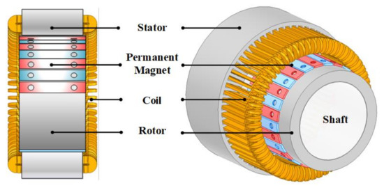
Figure 1.
Analysis model of PMSG.

Table 1.
Design Specifications.
3. A Semi-3D Technique Method
3.1. Magnetic Equivalent Circuit
PM overhang compensates for leakage flux and increases effective air gap flux. The increased air gap flux means a variation in elements through the existing magnetic circuit analysis. The magnetic equivalent circuit is a characteristic analytical method to calculate flux density based on an analogy of the electric circuit. The method can algebraically represent the relationship between the magnetic flux generated by the magnet to the air gap flux. From that, it is possible to define the operating point of PMSG [10,11,16,17,18].
Figure 2 shows the magnetic equivalent circuit of a surface permanent magnet device. Rsy and Rry are the magnetic reluctance of the stator and rotor yoke. RLmm is the leakage reluctance to express magnetic flux leaking to adjacent poles or other poles. Rlmr is the leakage reluctance between the rotor and the magnet. A permanent magnet and airgap consist of a magnetic flux source Φr and a reluctance of Rmo and Rg corresponding to the half pole. Figure 2a shows the magnetic equivalent circuit of a surface magnet type permanent magnet device. Figure 2c is the simplified equivalent circuit from (a) to (b) and (b) to (c). Rsy and Rry are negligible given the assumption that the magnetic saturation of the stator and rotor cores are neglected [10,11,19,20,21].
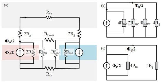
Figure 2.
Surface-attached permanent magnet device: (a) magnetic equivalent circuit, (b,c) simplifications of the magnetic circuit [10,11].
Equation (1) is the permeance for the magnetic flux source. To express the magnetic flux source and the air gap flux algebraically, first, the reluctance of the magnet was synthesized in parallel. For the convenience of calculating the parallel reluctance, it is expressed as permeance.
In Figure 2c, you can see the equivalent circuit composed of permeance and air gap reluctance. As Equation (2), the air gap flux Φg is expressed only as magnetic flux Φr by the equivalent circuit analysis, where PL is the leakage permeance of the magnet. In addition, the magnetic flux due to the magnet can also be expressed only with the magnetic flux r as follows:
The magnetic flux Φm was derived from Equation (3) by substituting Equation (2) from the relation between the air gap flux and the magnetic flux source. Therefore, from the derived Equations (2) and (3), the air gap flux along with the leakage factor can be newly defined [10,11]. The leakage factor is usually defined, in general, as the ratio of airgap flux to magnet flux [8]:
The Φg and Φm from Equation (4) is substituted by Equations (2) and (3) as follows:
Finally, given that Φg = BgAg and Φr = BrAm, Equation (5) gives another convenient formula for Bg [8].
where Bg is the average airgap flux-density across the airgap area Ag, and Am is the magnet pole area, both being circulated for one pole [8].
3.2. Operating Point of PMSG Using Magnetic Energy
As the magnetic flux increases using the PM overhang, the overall magnetic energy increases. The magnetic energy equation is as follows:
An equation considering the increase in the magnetic energy from Equation (1) can be derived. For the equation, the 3D magnetic energy is calculated the same as in the 2D model [7]. The equation is expressed as follows [19,20,21,22]:
The left side of Equation (8) is the magnetic energy of the 3D model, and the right side is the magnetic energy of the semi-3D model. Bm and Hm are the magnetic flux density and the magnetic field at the operating point of the 3D model, respectively. Bm′ and Hm′ are represented by the operating points of the semi-3D model considering the overhang. V and V′ are the volumes of the PM. The volume is calculated using the axial length and the area per pole. Assuming that the thickness values of the PMs of the 3D and semi-3D models are the same, the volume varies depending on the length of the overhang, resulting in a variation in the operating point [15].
Figure 3 shows the demagnetization curve. It can yield the permeance coefficient (PC) as a variation from a to a′. The PC in Equation (9) is defined as the load line slope from being derived in Equation (6). The slope can be expressed algebraically in the Cartesian coordinate system by the magnetic field and magnetic flux density shown in Figure 2. In addition, the PC can be expressed as Equation (9) [8,13,14].
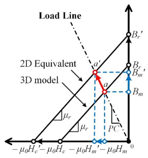
Figure 3.
Demagnetization curve.
In Equation (9), fLKG is the leakage factor, which typically has a value in the range of 0.85–0.95, with a calculated median value of 0.9, discretionally [8]. g and LPM are the radial width of the air gap and the PM, per pole, respectively. Ag and Am are areas of the air gap and the axial cross-sectional per pole of the PM, respectively.
From Equations (8) and (9), the semi-3D permanent magnet operating point equation can be derived as follows:
The results of the equation for the operating point are summarized in Table 2. The residual magnetic flux density, Br, obtained from Equations (10) and (11), ranges from 1.1056 [T] to 1.1209 [T]. Br was applied to the semi-3D model to consider the overhang structure.
Table 2.
Equivalent results considering overhang.
3.3. Analysis Method Considering Bolting and Overhang
The magnetic energy is used to consider the overhang; however, the method to analyze the bolting is different. The bolting does not need to consider the length of the PM for the overhang. This is because the effect on the increase in the magnetic energy is applied in the overhang region. Instead, it is necessary to understand the bolting structure of the 3D model and change it to a semi-3D model.
The bolting structure has a cylindrical form, as shown in Figure 4a. However, radial cylindrical columns cannot be expressed in the 2D FEM. Therefore, in 2D, the bolting is modeled as a rectangular parallelepiped volume. For simplification, the bolting volumes of the 2D and 3D models are the same in the bolting regions. The equation for calculating the width is expressed as follows:
where BWidth is the bolting width obtained from Equation (12) for the semi-3D model. DBol is the diameter of the 3D bolting. The diameter is used along the axial length of the bolting region. MThick is the thickness of the PM. Figure 4 shows a part of the analysis model.
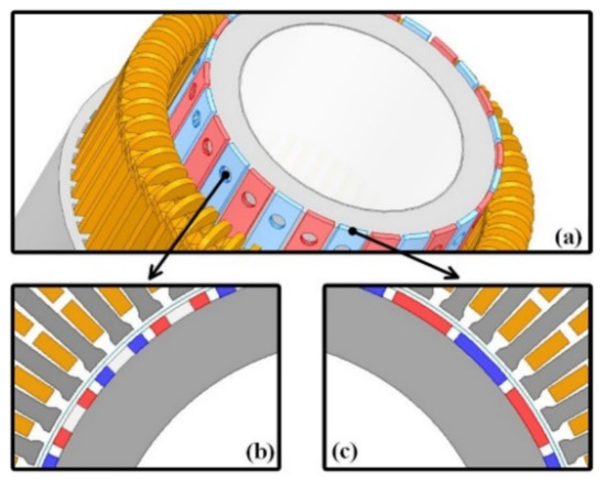
Figure 4.
Analysis models: (a) 3D model, (b) PM with bolting, (c) PM without bolting.
Figure 4a–c are the 3D model, bolting region, and overhang region, respectively. The semi-3D model considering a bolting and an overhang can be analyzed by dividing it into corresponding regions, as in the above method. Subsequently, characteristic analyses of the divided regions are performed based on superposition [5]. Table 3 lists the magnetic flux density applied to each region.
Table 3.
Axial length and flux density for analysis model.
3.4. Equivalent Circuit Method
The equivalent circuit method consists of the circuit parameters obtained from the design specifications of a PMSG. It assumes the induced voltage of a generator as a sine wave. Subsequently, the output characteristics are derived using the equivalent resistance, synchronous inductance, and load resistance based on the circuit parameters. Among the circuit parameters, the phase resistance was directly calculated through the equation. The no-load back electromotive force (EMF) and a phase inductance were derived through FEM. The voltage, current, and power calculated using the equivalent circuit vary according to the circuit parameters. Figure 5 presents the equivalent circuit of the PMSG with an AC load.
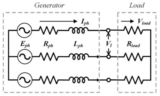
Figure 5.
Equivalent circuit of PMSG with an AC load.
Equations (13)–(15) yield the circuit parameters. Eph is the no-load EMF of the AC load. Rph is the phase resistance calculated to 1.3 Ω. Lc is the length of winding in a coil. The output characteristics equations are as follows:
The output voltage can be derived from the no-load back EMF by the voltage divider rule. Vload in Equation (16) is derived from Rload, which is the load resistance [9]. Therefore, the output current is also obtained from Equation (17). The output power, Pout, is calculated using the output voltage and the current obtained. In addition, among the elements composing the equation, inductance Lph derived through 2D and 3D FEM is the circuit parameter of the equivalent circuit. w is the speed.
Table 4 lists the considered circuit parameters. It also summarizes the output characteristics of PMSG determined from Equations (16)–(18) according to the circuit parameters.
Table 4.
Circuit parameters.
4. Analysis and Experiment Results
4.1. Experiment Model
Figure 6a–c show the manufactured model—specifically, the experimental set, stator, and rotor with the PM bolting, respectively. The bolting material is steel, which affects performance. The characteristic analyses of the model have performed the characteristic analysis to AC.
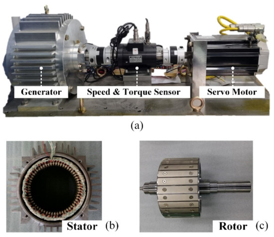
Figure 6.
Manufactured model: (a) experimental set, (b) stator, and (c) rotor.
4.2. No-Load Analysis
Figure 7 shows the phase-to-phase voltage results from the no-load analysis. Figure 7a shows the voltage according to the effect of the overhang and bolting. The overhang compensated for the leakage flux caused by the end effect and showed a voltage increase rate of about 0.6% compared to that without consideration. Although the bolting of PMs reduces output performance due to the reduction of permanent magnets, the advantages in the manufacturing process are more useful. In addition, it can be seen from the semi-3D analysis that the output is compensated for by the overhang.
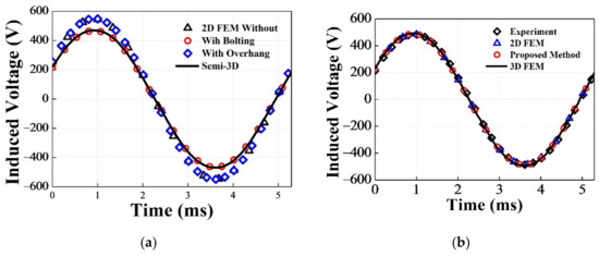
Figure 7.
No-load characteristic curve: (a) effect of the overhang and bolting, (b) comparison of the results.
In Figure 7b, The 2D FEM is the characteristic curve that does not consider the operating point of PM. The proposed method considers the overhang and the bolting in the semi-3D model. For verification, the results are compared to the 3D FEM and experimental result. In the analysis specifications, the speed is 800 rpm. Table 4 summarizes the compared results. The error between the semi-3D analysis and the experiment (Exp.) is less than 4%. Although the 3D FEM has a lower error rate than the semi-3D analysis, the results of the latter are similar to the experimental ones.
4.3. AC Load Analysis
Figure 8 shows the characteristic curves of the semi-3D model under AC load. Figure 8a,b present the output power–voltage and current–voltage curves, respectively. For the PMSG model analysis, the overhang is considered using the operating point. Subsequently, the circuit parameters are applied to the equivalent circuit with the AC load.
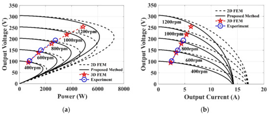
Figure 8.
Load characteristic curve: (a) power–voltage curves, (b) current–voltage curves.
For accurate results, inductances derived from 2D and 3D FEMs are used as circuit parameters, as listed in Table 4. The characteristic curve shows that the output has applied inductance, as shown in Figure 8a,b, respectively. The 2D FEM shows the results using the inductance derived from the 2D FEM, and the proposed method presents the results using the inductance derived from the 3D FEM. The result using the inductance derived from 3D FEM matched better with 3D FEM than the result using 2D FEM inductance. Table 5 lists the output power results according to the speed when Rload is 40 Ω. From the results, the semi-3D analysis and 3D FEM are compared to the experiment, and the error rate is derived. The error between the semi-3D analysis and Exp. is less than 4% at 600 rpm. Therefore, the semi-3D analysis using the equivalent circuit is similar to the characteristic analysis from Exp.
Table 5.
AC load analysis results according to speed.
5. Conclusions
In this study, we performed the characteristic analysis of a PMSG considering an overhang and bolting. First, for considering the overhang structure, the operating point was obtained using the magnetic energy equation. Subsequently, the equivalent circuit of the PMSG considered inductance for the output characteristics analysis. The proposed method uses inductance derived from the 3D FEM. The semi-3D analysis applying two methods derived results based on superposition. The results of the proposed method were compared to 3D FEM and Exp. analysis results. However, the validity of the proposed method was verified by the similarity of these results. Therefore, it is considered that the method using inductance derived from the 3D FEM will be more useful than the previous one using the 2D inductance.
Author Contributions
J.-Y.C.: conceptualization, review, and editing; J.-S.H.: analysis and original draft preparation; H.-K.L.: experiment and co-simulation; J.N.: review and editing; K.-H.S.: co-simulation and review; K.-H.K.: funding acquisition and supervision. All authors have read and agreed to the published version of the manuscript.
Funding
This work was supported by the Korea Institute of Energy Technology Evaluation and Planning (KETEP) and the Ministry of Trade, Industry & Energy (MOTIE) of the Republic of Korea. (No. 20183010025420), This work was supported by the Korea Institute of Energy Technology Evaluation and Planning (KETEP) grant funded by the Korea government (MOTIE) (No. 20213030020320).
Institutional Review Board Statement
Not applicable.
Informed Consent Statement
Not applicable.
Data Availability Statement
The data presented in this study are available on request from the corresponding author.
Conflicts of Interest
The authors declare no conflict of interest.
References
- Hong, K.P.; Kang, G.H.; Lee, S.K. Design of a 6kW permanent magnet synchronous generator with low speed and high torque for gyro wave power generation. J. Korean Soc. Mar. Eng. 2017, 41, 878–883. [Google Scholar]
- O’Sullivan, D.L.; Lewis, A.W. Generator Selection and Comparative Performance in Offshore Oscillating Water Column Ocean Wave Energy Converters. IEEE Trans. Energy Convers. 2011, 26, 603–614. [Google Scholar] [CrossRef]
- Lee, C.W. Calculation of Self and Mutual Inductances in Multi-Phase Permanent Magnet Synchronous Motor. J. Korean Magn. Soc. 2017, 27, 9–17. [Google Scholar] [CrossRef][Green Version]
- Choi, J.Y.; Kang, H.B.; Hong, S.A. Review of Linear Permanent Magnet Generator for Wave Energy Converter according to Magnetic Circuit Construction. KAOSTS 2014, 2397–2402. [Google Scholar]
- Shin, K.H. Characteristic Analysis of Wave Power Generator Considering Bolting to Fix Permanent Magnet Based on Analytical Method. IEEE Trans. Magn. 2019, 55, 7501805. [Google Scholar] [CrossRef]
- Woo, D.-K.; Lim, D.-K.; Yeo, H.-K.; Ro, J.-S.; Jung, H.-K. A 2-D finite-element analysis for a permanent magnet synchronous motor taking an overhang effect into consideration. IEEE Trans. Magn. 2013, 49, 4894–4899. [Google Scholar] [CrossRef]
- Lee, T.-Y.; Seo, M.-K.; Kim, Y.-J.; Jung, S.-Y. Motor design and characteristics comparison of outer-rotor-type BLDC motor and BLAC motor based on numerical analysis. IEEE Trans. Appl. Supercond. 2016, 26, 5205506. [Google Scholar] [CrossRef]
- Hendershot, J.R., Jr.; Miller, T.J.E. Design of Brushless Permanent-Magnet Motors; Magna Physics Publishing and Clarendon Press: Oxford, UK, 1994. [Google Scholar]
- Chan, T.F.; Lai, L.L.; Yan, L.-T. Performance of a three-phase AC generator with inset NdFeB permanent-magnet rotor. IEEE Trans. Energy Convers. 2004, 19, 88–94. [Google Scholar] [CrossRef]
- Yeo, H.-K.; Lim, D.-K.; Woo, D.-K.; Ro, J.-S.; Jung, H.-K. Magnetic Equivalent Circuit Model Considering Overhang Structure of a Surface-Mounted Permanent-Magnet Motor. IEEE Trans. Magn. 2015, 51, 8201004. [Google Scholar]
- Qu, R.; Lipo, T.A. Analysis and modeling of air-gap and zigzag leakage fluxes in a surface-mounted permanent-magnet Machine. IEEE Trans. Ind. Appl. 2004, 40, 121–127. [Google Scholar] [CrossRef]
- Delmonte, N.; Barater, D.; Giuliani, F.; Cova, P.; Buticchi, G. Review of Oscillating Water Column Converters. IEEE Trans. Ind. Appl. 2016, 52, 1698–1710. [Google Scholar] [CrossRef]
- Ko, Y.; Song, J.; Seo, M.; Han, W.; Kim, Y.; Jung, S. Analytical Method for Overhang Effect of Surface-Mounted Permanent-Magnet Motor Using Conformal Mapping. IEEE Trans. Magn. 2018, 54, 8208005. [Google Scholar] [CrossRef]
- Koo, M.; Choi, J.; Park, Y.; Jang, S. Influence of Rotor Overhang Variation on Generating Performance of Axial Flux Permanent Magnet Machine Based on 3-D Analytical Method. IEEE Trans. Magn. 2014, 50, 8205905. [Google Scholar] [CrossRef]
- Yeo, H.; Ro, J. Novel Analytical Method for Overhang Effects in Surface-Mounted Permanent-Magnet Machines. IEEE Access 2019, 7, 148453–148461. [Google Scholar] [CrossRef]
- Sheikh-Ghalavand, B.; Vaez-Zadeh, S.; Isfahani, A.H. An Improved Magnetic Equivalent Circuit Model for Iron-Core Linear Permanent-Magnet Synchronous Motors. IEEE Trans. Magn. 2010, 46, 112–120. [Google Scholar] [CrossRef]
- Moallem, M.; Dawson, G.E. An improved magnetic equivalent circuit method for predicting the characteristics of highly saturated electromagnetic devices. IEEE Trans. Magn. 1998, 34, 3632–3635. [Google Scholar] [CrossRef]
- Mi, C.; Filippa, M.; Liu, W.; Ma, R. Analytical method for predicting the air-gap flux of interior-type permanent-magnet machines. IEEE Trans. Magn. 2004, 40, 50–58. [Google Scholar] [CrossRef]
- Tsai, W.-B.; Chang, T.-Y. Analysis of flux leakage in a brushless permanent-magnet motor with embedded magnets. IEEE Trans. Magn. 1999, 35, 543–547. [Google Scholar] [CrossRef]
- Hsieh, M.; Hsu, Y. A Generalized Magnetic Circuit Modeling Approach for Design of Surface Permanent-Magnet Machines. IEEE Trans. Ind. Electron. 2012, 59, 779–792. [Google Scholar] [CrossRef]
- Kano, Y.; Kosaka, T.; Matsui, N. Simple nonlinear magnetic analysis for permanent-magnet motors. IEEE Trans. Ind. Appl. 2005, 41, 1205–1214. [Google Scholar] [CrossRef]
- Song, J.; Lee, J.H.; Kim, Y.; Jung, S. Computational Method of Effective Remanence Flux Density to Consider PM Overhang Effect for Spoke-Type PM Motor With 2-D Analysis Using Magnetic Energy. IEEE Trans. Magn. 2016, 52, 8200304. [Google Scholar] [CrossRef]
Publisher’s Note: MDPI stays neutral with regard to jurisdictional claims in published maps and institutional affiliations. |
© 2022 by the authors. Licensee MDPI, Basel, Switzerland. This article is an open access article distributed under the terms and conditions of the Creative Commons Attribution (CC BY) license (https://creativecommons.org/licenses/by/4.0/).