1. Introduction
Traditional electrolytic capacitors have been popularly used in DC-link inverters for more than 40 years due to their energy storage capabilities and excellent DC-voltage filtering abilities. However, these electrolytic capacitors are very expensive and have large volumes and a short lifespan. To solve these problems, several researchers have focused on using small-film capacitors to replace electrolytic capacitors in low-power appliances. However, by using small-film capacitors, the input currents and DC-link voltages fluctuate and require advanced control algorithms to smooth the fluctuations. Several researchers have proposed different control algorithms for these three-phase diode-rectified small-film DC-link drive systems. For example, Inazuma et al. proposed a repetitive controller, which was very complicated and required a lot of computation time for a DSP to execute the control algorithm [
1]. Zhao et al. investigated inverter power control in which a phase-locked loop, a power reference generator, and a power resonant controller were used. The power control system, therefore, was too complicated [
2]. Bau used a hybrid control for a small DC-link capacitor drive system [
3] in which a PI controller and a resonant controller were used. However, the implementation and analysis of the system were both very difficult. Son et al. implemented grid current control for a small DC-link capacitor motor drive system [
4], which included current, speed, and power controllers. As a result, the implemented system became very complicated. Son realized that direct power control for a small-capacitor DC-link motor drive system required a current reference generator, motor current control, power control, and phase-locked loop [
5]. Li proposed a novel active damping control [
6], in which a DC-link small-film capacitor and a first-order high-pass filter were used. However, this did not effectively reduce the output harmonic currents of the inverter.
Improving the control of the power of small-film DC-link capacitor PMSM drive systems is important, but only a few researchers have focused on this issue. For example, a few researchers have recently investigated feedback linearizing control [
7], sliding mode control [
8], resonance reduction control [
9], voltage modulation techniques which use virtual positive impedance control [
10], and improved fast control of DC-link voltages [
11]. However, the control methods proposed in [
7,
8,
9,
10,
11] were very difficult to implement by using a DSP.
Little-to-no previous research has been done on using predictive control for three-phase DC-link capacitor PMSM drive systems. To fill this research gap, in this paper, predictive speed- and current-loop controllers are implemented to enhance the performance of three-phase small-film DC-link IPMSM drive systems, which provide good transient responses, good load disturbance responses, and good tracking responses. In addition, the harmonic currents of the PMSM are also obviously reduced. The main contributions of this paper include two parts. The first part proposes a fifth-order band-pass filter to replace a traditional first-order high-pass filter. By using a fifth-order band-pass filter, the output a-phase, b-phase, and c-phase currents of the inverter are closer to the desired square current waveforms. In addition, by using the proposed predictive control, the dynamic speed responses are greatly improved, and the harmonic currents of the motor are significantly reduced. Moreover, the predictive controllers are easily implemented by using a DSP, which only requires simple addition, subtraction, multiplication, division, and comparison, unlike other advanced control algorithms. The practical applications of this paper include many home and industrial uses, such as air conditioners, vacuum cleaners, washing machines, and heaters for diode manufacturing processes [
12,
13]. To the authors’ best knowledge, the ideas for using predictive controllers that are proposed in this paper are original and have not been investigated in previous papers [
1,
2,
3,
4,
5,
6,
7,
8,
9,
10,
11,
12,
13]. Furthermore, a high-order band-pass filter for active damping control is also an original idea in this paper and has not been published in previous papers [
1,
2,
3,
4,
5,
6,
7,
8,
9,
10,
11,
12,
13].
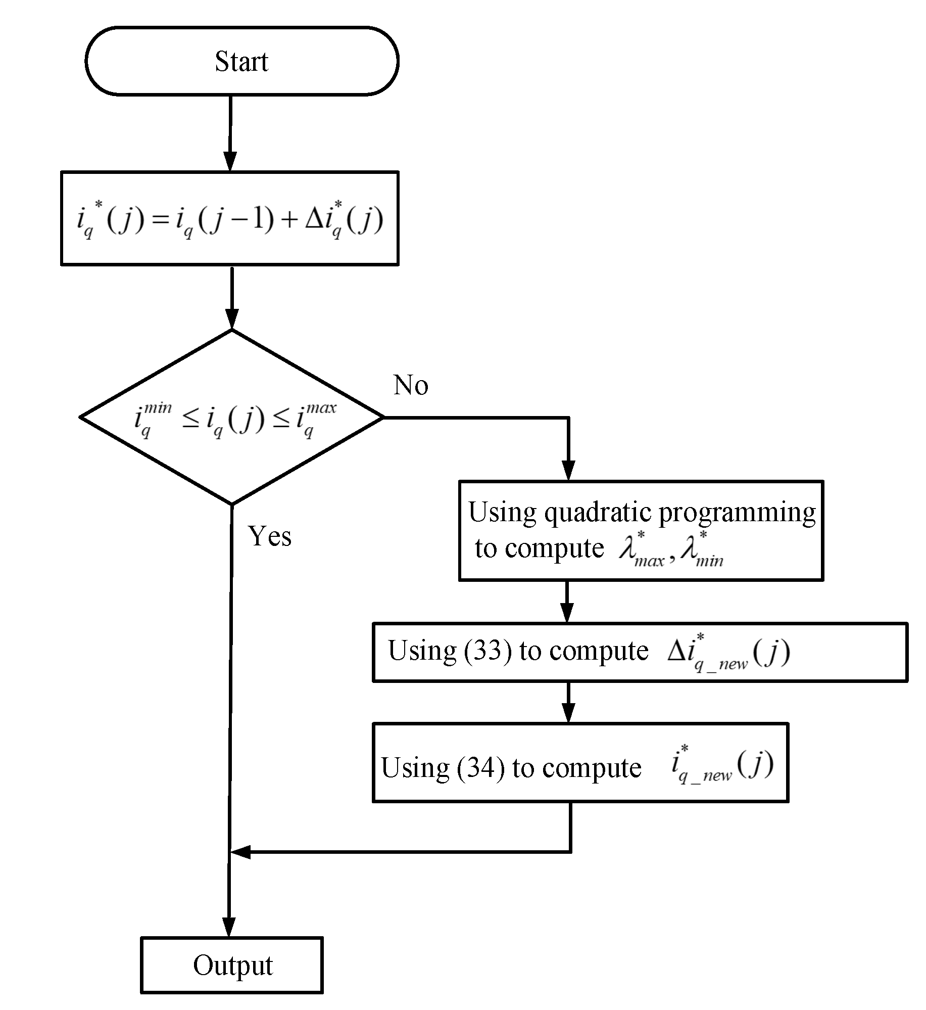
5. Implementation
Figure 7 shows the block diagram of the implemented IPMSM drive system. First, the speed command
is compared with the real speed
to obtain the speed error. Second, the predictive speed controller uses the speed error
to generate the q-axis current command
and uses the real speed to generate the d-axis current command
. Then, the
is compared to the
in order to create the q-axis voltage command
, and then the
is compared to the
in order to create
. Next, the
is added to the active damping q-axis voltage
, and then the
is added to the active damping d-axis voltage
. After that, the summations of the
and
and the summations of the
and
are transferred into
,
, and
. Finally, the
,
, and
use a space-vector pulse-width modulation to generate the triggering signals of the six IGBTs in order to drive the IPMSM, and then a closed-loop drive system is achieved.
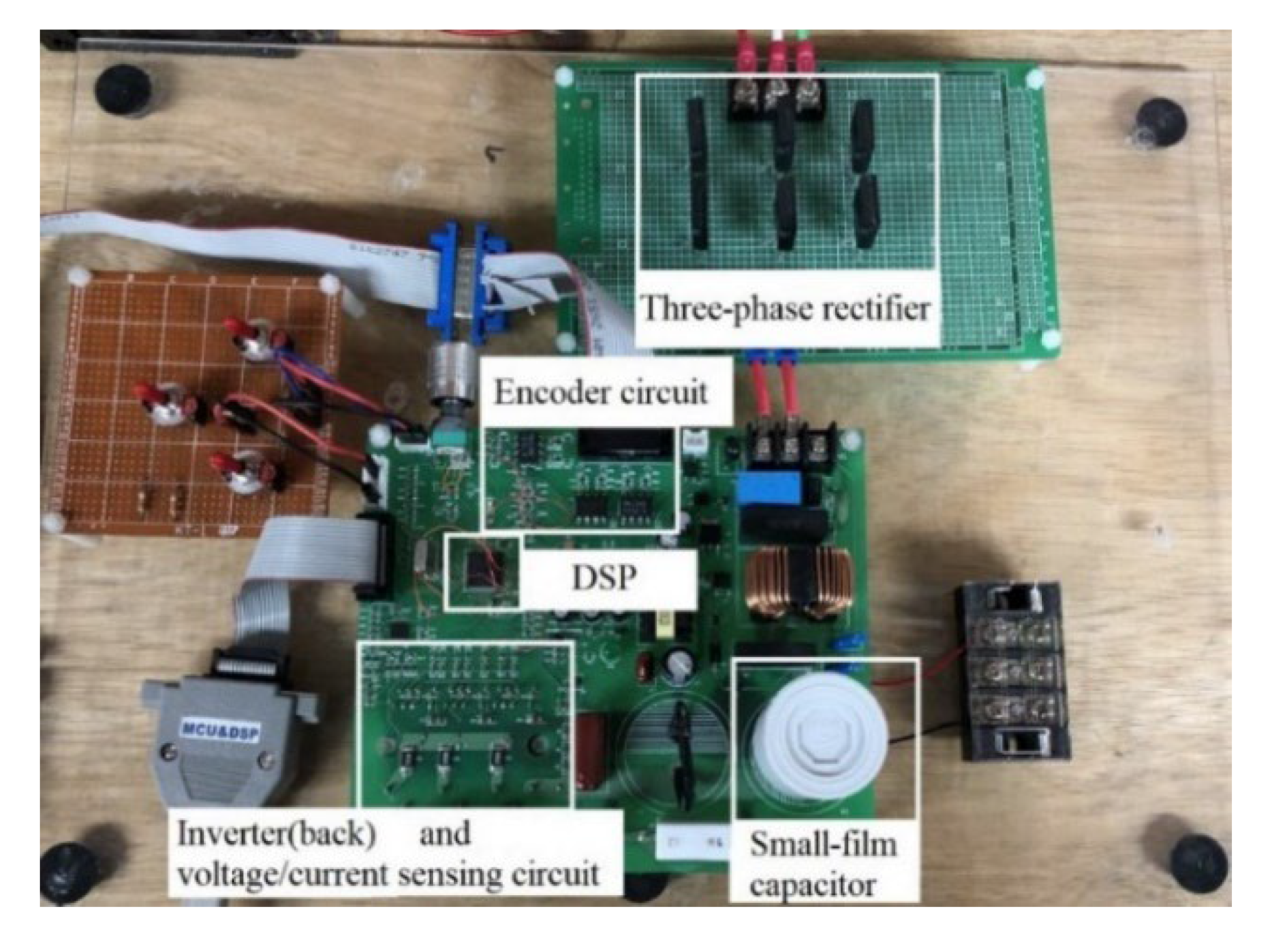
Figure 8 shows a photograph of the hardware circuits in this proposed drive system, including a three-phase rectifier, an encoder circuit, a DSP which is used to execute the high-frequency high-order active damping control, the predictive speed-loop control, and the predictive current-loop control, a six-IGBT inverter in the back of the PCB, voltage sensing circuits, current sensing circuits, and a small-film capacitor which has a much smaller size than traditional electrolytic capacitors. A comparison of the volume, weight, and cost of a traditional electrolytic capacitor and a small-film capacitor is shown in
Table 1 [
20]. This small-film capacitor uses Metal Injection Molding (MIM) technology [
21], and it can be used for low-speed, middle-speed, and high-speed motor drive systems.
6. Simulated and Experimental Results
A 10 small-film capacitor is used here, and the DC-bus voltage varies from 270 V to 311 V with a frequency of 360 Hz. Furthermore, a three-phase 220 60 Hz AC source is used. A 4-pole IPMSM with a rated power of 500 W, a rated current of 3 A, and a rated speed of 1800 r/min is also used. This motor has the following parameters: the stator resistance is 1.9 , the d-axis inductance is 15.1 mH, the q-axis inductance is 31 mH, the flux linkage is 0.227 V.s/rad, the inertia of the motor is 0.0005 kg.m, and the viscous coefficient of the motor is 0.003 N.m.s/rad. This simulation uses Simulink software, and the is 2.5 A and the is 0.2 A. In order to verify the correctness of the theoretical analysis, several simulated and measured results are shown and compared, which can be divided into three categories. The first category includes the input AC source voltages, the input AC source currents, and the DC-link voltages using a 440 electrolytic capacitor and a 10 small-film capacitor. The second category includes the measured current waveforms using a predictive current controller and a PI controller. The third category includes the measured speed responses with and without constraints, including transient responses, load disturbance responses, and sinusoidal tracking and triangular tracking responses.
The measured results of the first category are demonstrated in
Figure 9a,b,
Figure 10,
Figure 11,
Figure 12a,b.
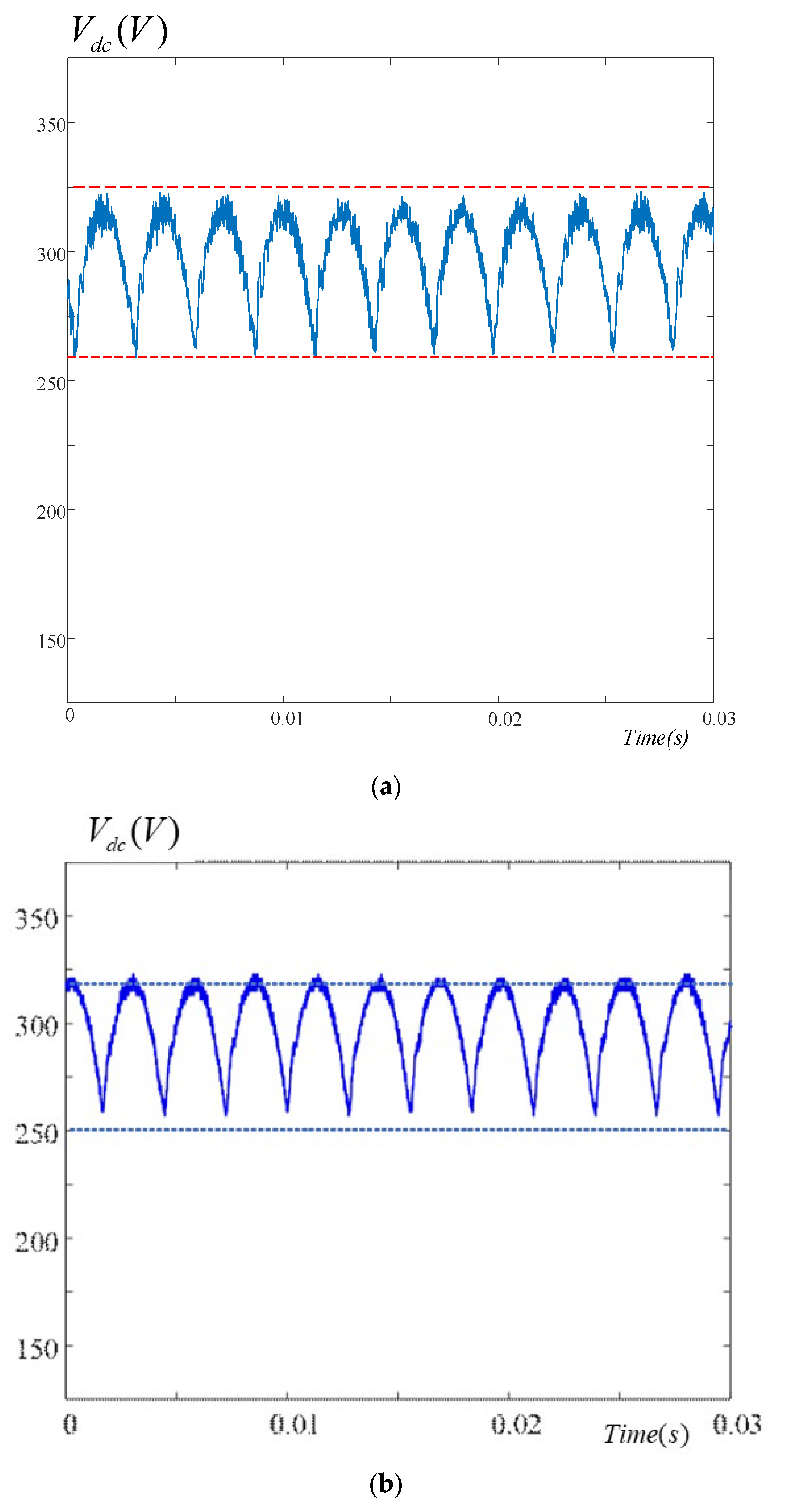
Figure 9a demonstrates the simulated DC-link voltages using a small-film capacitor. The simulated DC-link voltages vary from 258 V to 320 V within a 2.76 ms.
Figure 9b demonstrates the measured results using the same process. If we compare
Figure 9a,b, we see that both of them have the same voltage and period fluctuations. We can see that the DC-bus voltage creates more serious fluctuations than traditional electrolytic capacitors.
Figure 10a illustrates the simulated input currents at the AC source. The input current has a 3.5 A peak when using a 440
electrolytic capacitor.
Figure 10b illustrates the measured results by using the same process. After comparing
Figure 10a,b, we can see that both of them have the same peak current fluctuations and also have the same two discontinuous current pulsations in each half cycle. The major reason for this is that when the input voltage is smaller than the DC-bus voltage, the rectifying diodes are turned off, and then the a-phase current becomes zero.
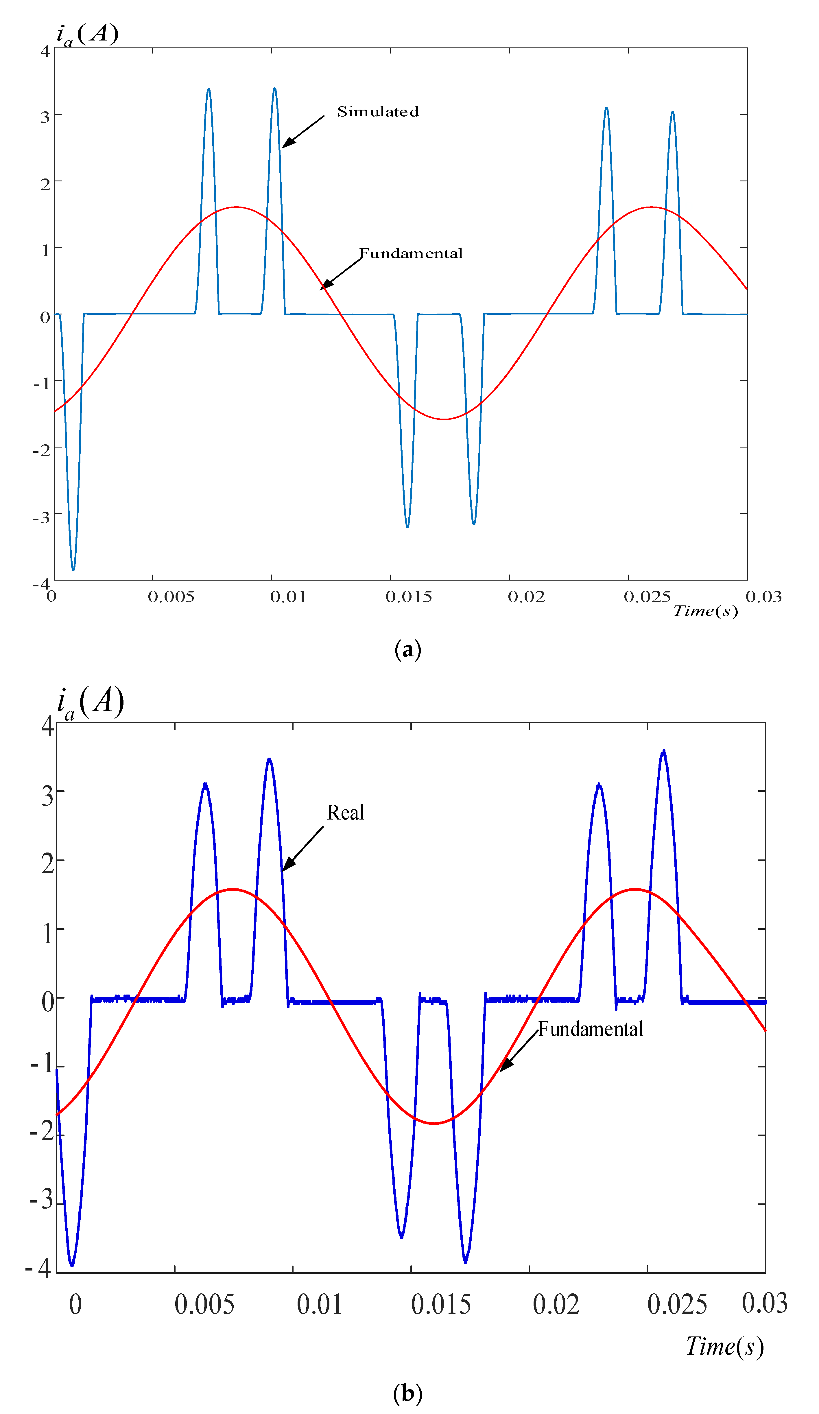
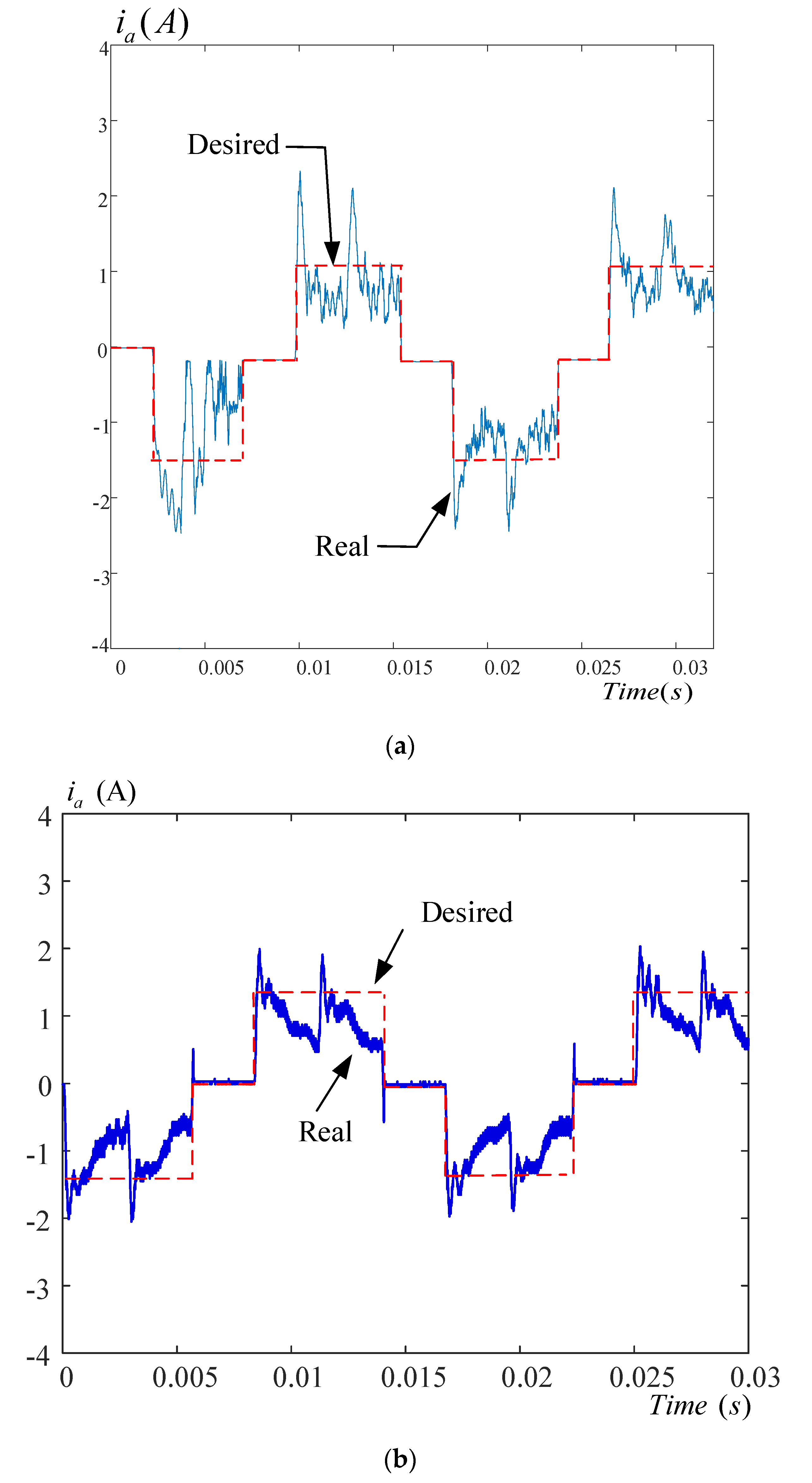
Figure 11a shows the simulated input a-phase current at the AC source by using a 10
small-film capacitor without using active damping control. Here, we can see that the input current has obvious pulsations.
Figure 11b shows the measured waveform in the same situation. Both
Figure 11a,b show that the desired square-wave currents are different from the measured currents due to their small inductance at the input AC source. When a small-film capacitor is used, the a-phase current changes from pulses into square waveforms because the DC-bus voltage is reduced.
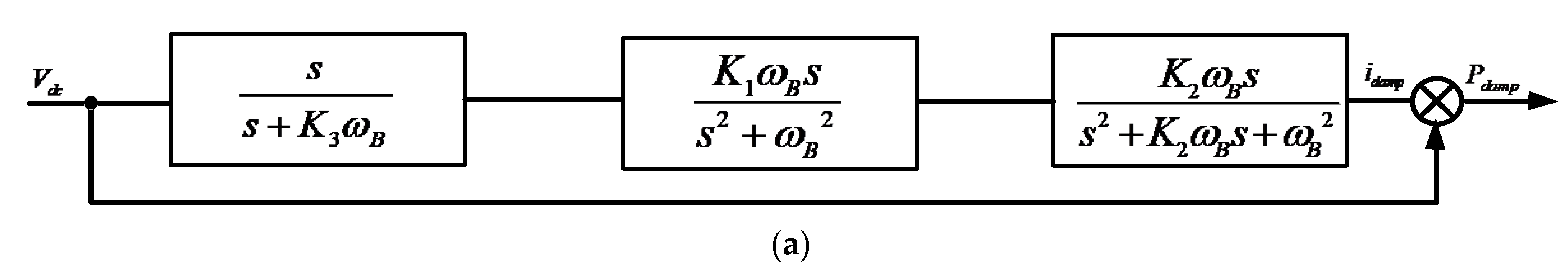
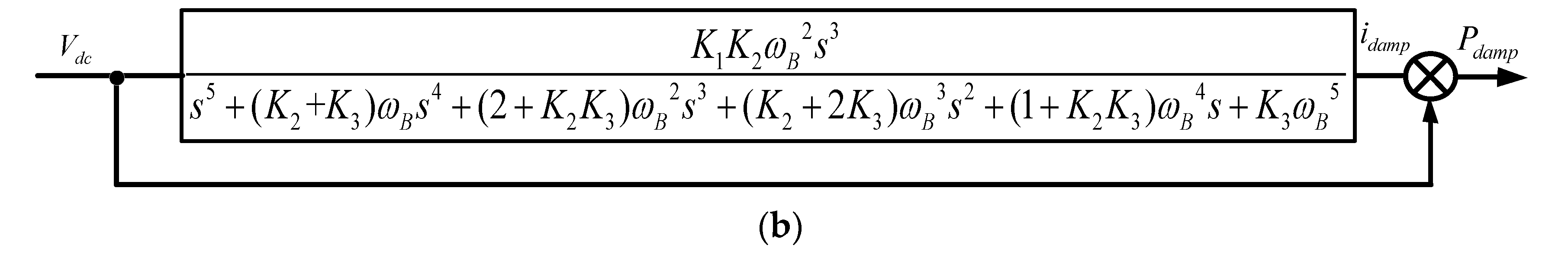
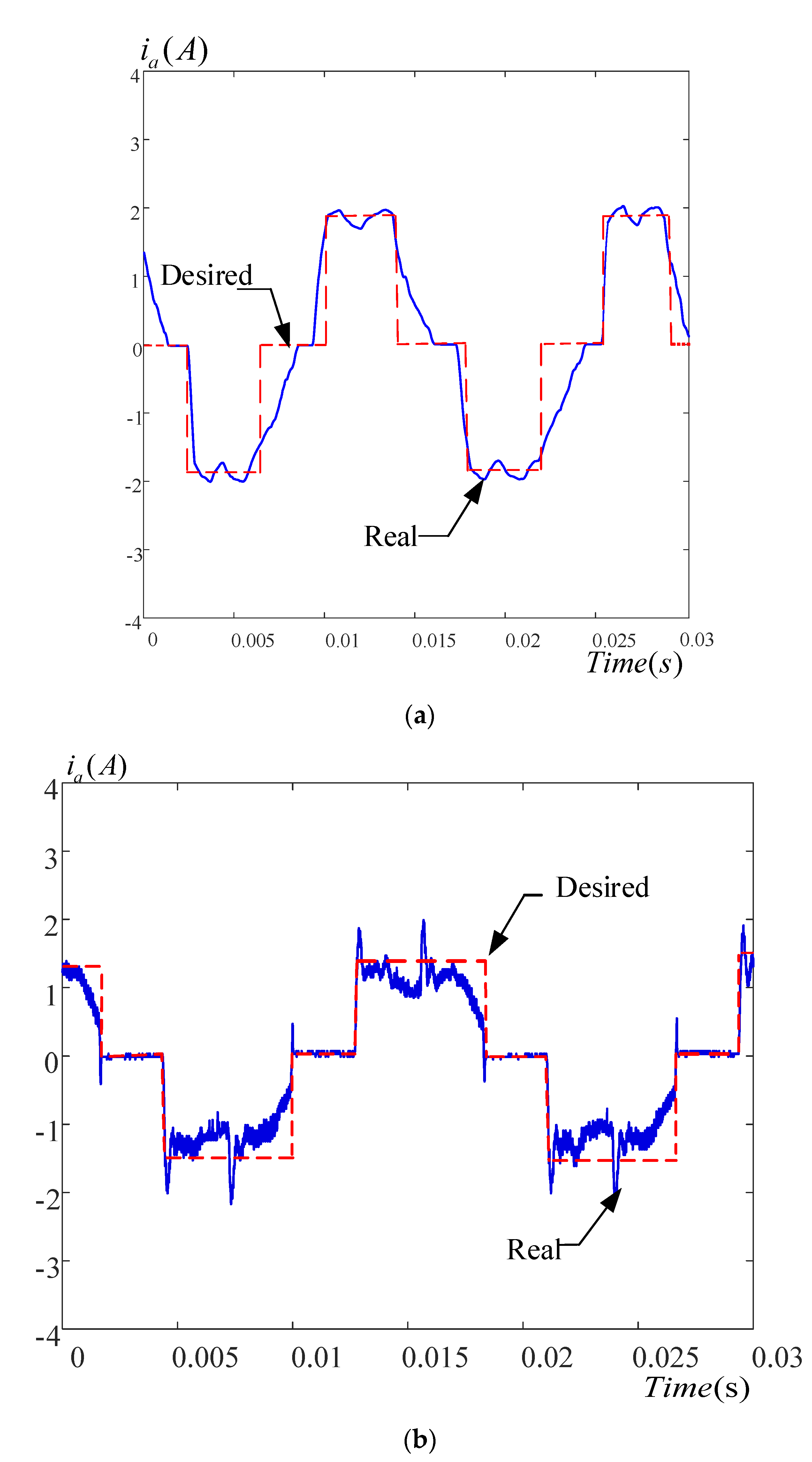
Figure 12a displays the measured input current waveform using a high-order band-pass active damping control. The transfer function is
with
= 720
,
K = 1.0468,
K 4.1095, and
K = 0.00927.
Figure 12b shows the measured input current using a first-order high-pass active damping control, which has a bandwidth of 5 kHz, and a cut off frequency of 2.26 kHz and can be expressed as
. As we can observe, the results in
Figure 12a show a better performance than the results in
Figure 12b. The major reason for this is that the fifth-order band-pass filter provides a wider middle-frequency bandwidth than the high-pass filter.
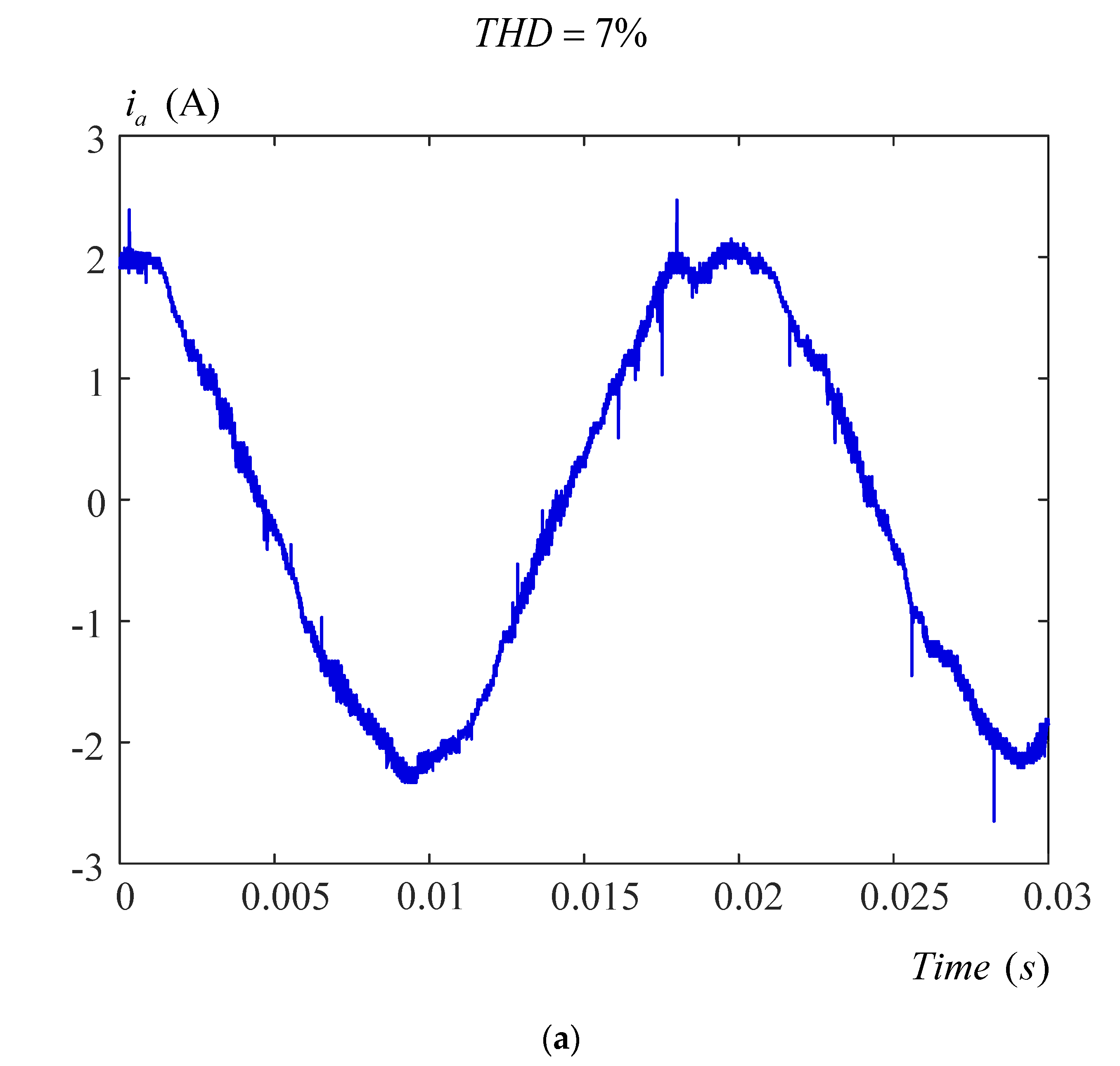
The measured results of the secondary category are demonstrated in
Figure 13a,b.
Figure 13a demonstrates the measured a-phase motor current by using PI current control, which generates a 7% THD.
Figure 13b demonstrates the measured a-phase current by using predictive current control, which has a 6.4% THD. Again, the predictive current control provides better performance than the PI current control. The major reason for this is that the predictive control uses past, present, and future information to control the system; however, the PI control only uses present information to control the system.
The simulated and measured results of the third category are shown in
Figure 14a,b,
Figure 15,
Figure 16,
Figure 17,
Figure 18a,b.
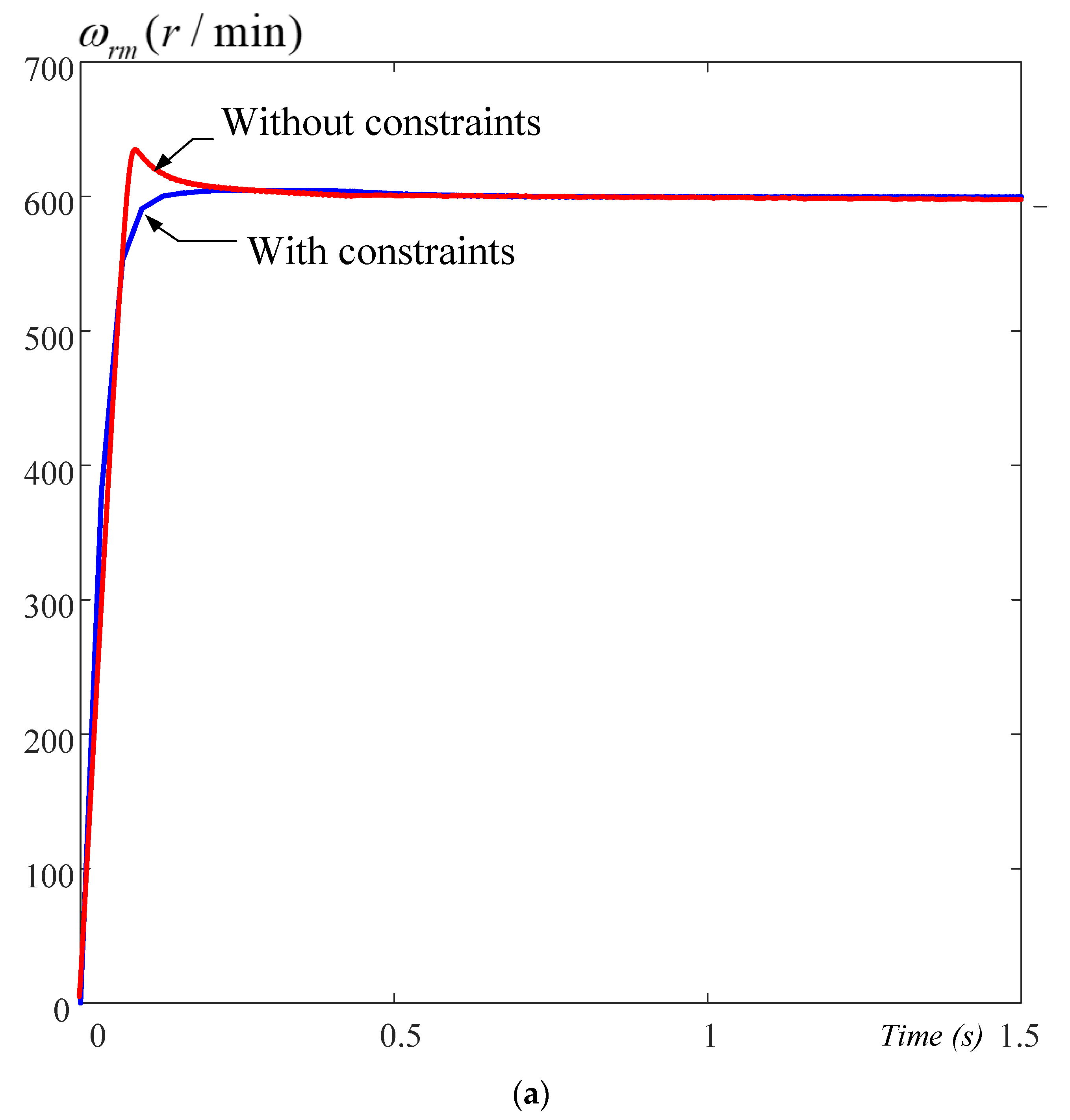
Figure 14a shows the simulated results of the predictive control with constraints and the predictive control without constraints. The predictive control with constraints has a lower overshoot than the predictive control without constraints.
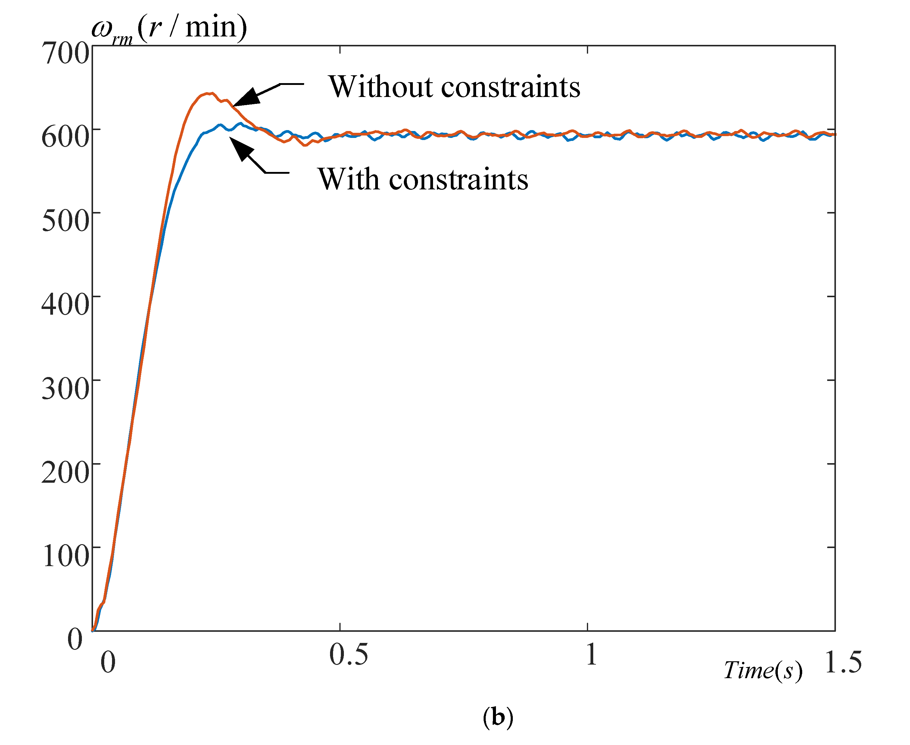
Figure 14b illustrates the measured results, which provide the same conclusions as the simulated results.
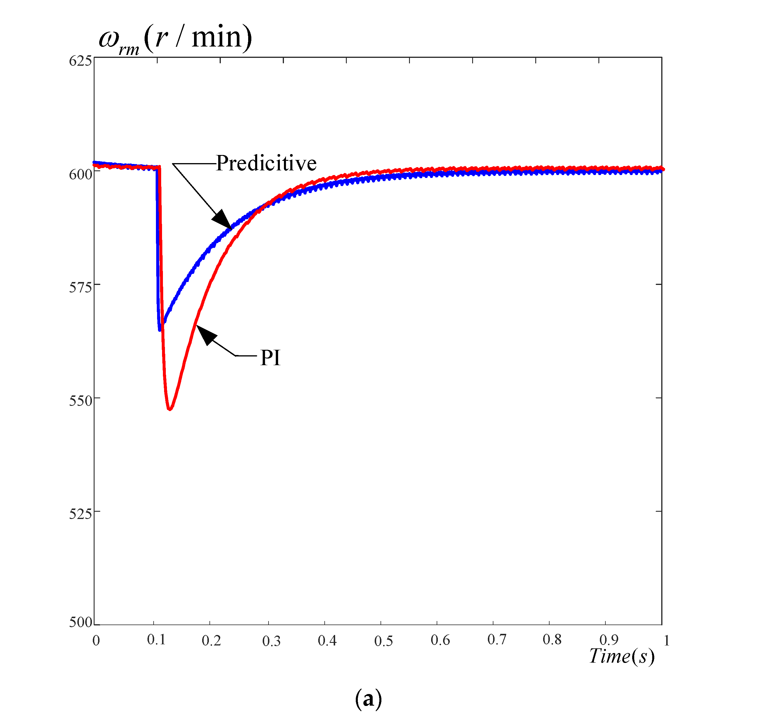
Figure 15a shows the simulated results of the load disturbance with a 2 N.m external load.
Figure 15b shows the measured results of the same situation. Both the simulated and measured results show that the predictive control provides a lower speed drop and a quicker recovery time than the PI control does. This is because the predictive control uses past, present, and future information to control the system. In addition, a real-time optimization of the cost function is applied. As a result, the predictive control shows better performance than the PI control.
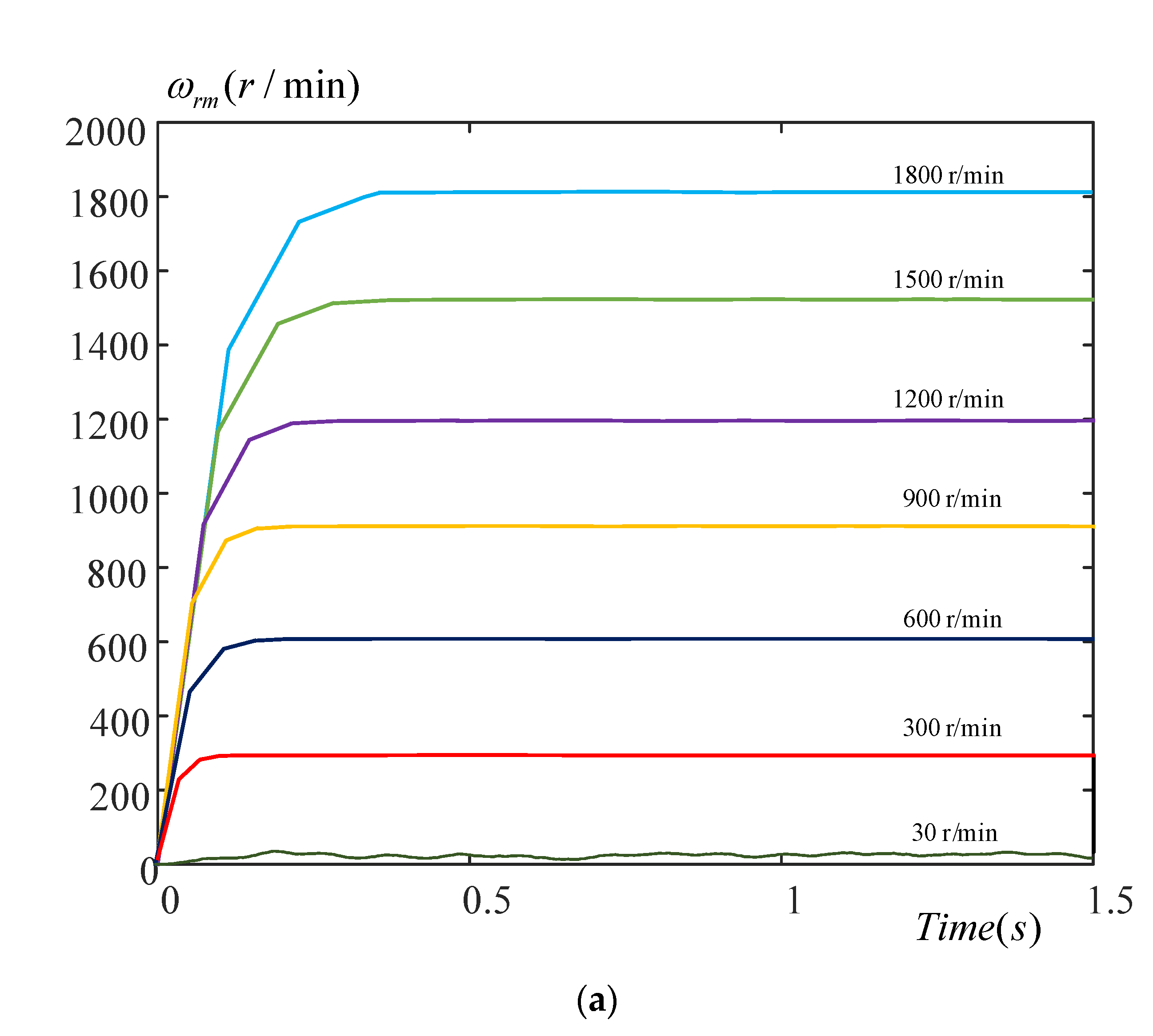
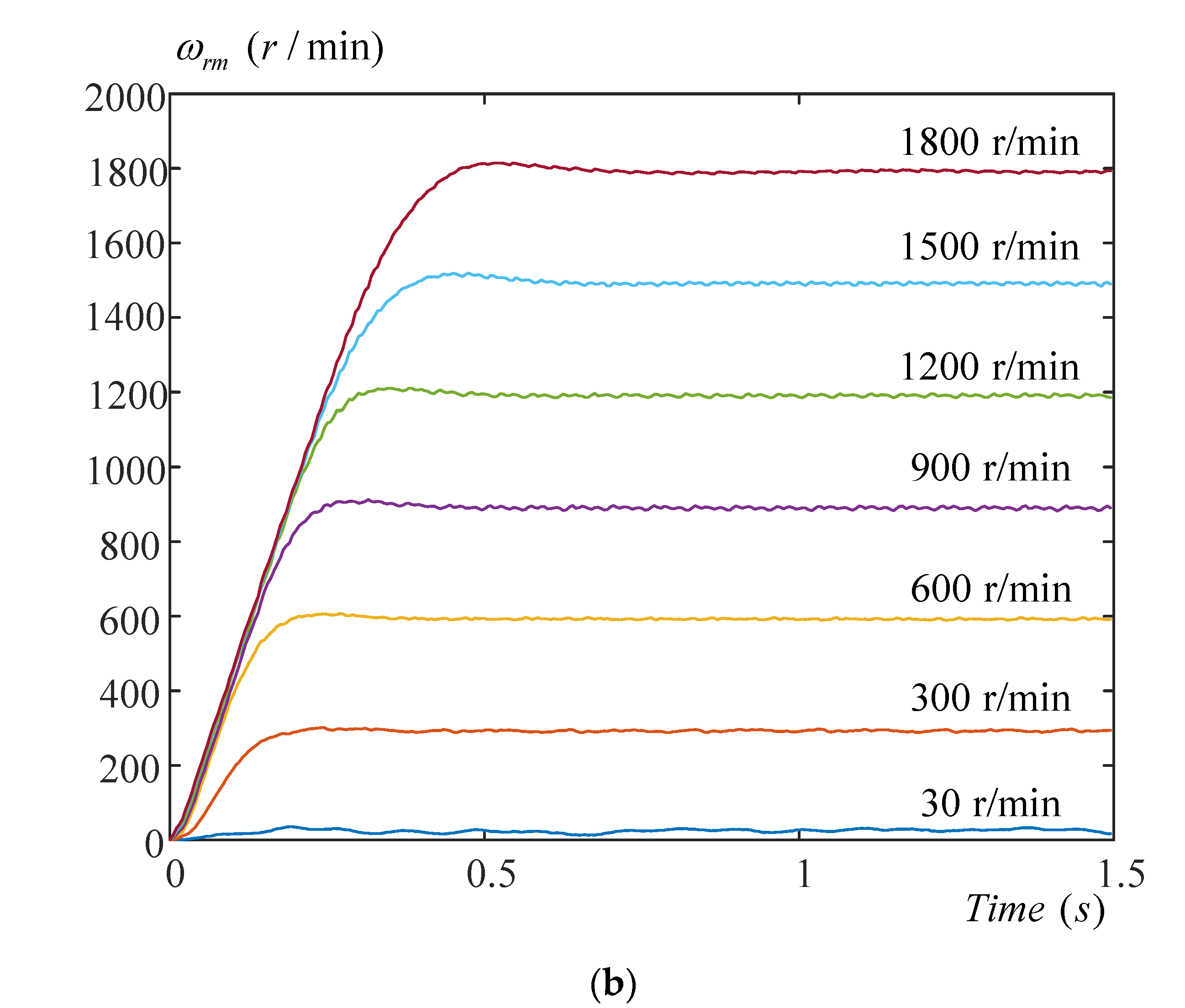
Figure 16a shows the simulated speed responses from 30 r/min to 1800 r/min, and
Figure 16b shows the actual measured responses. The results of simulated and measured responses are very similar.
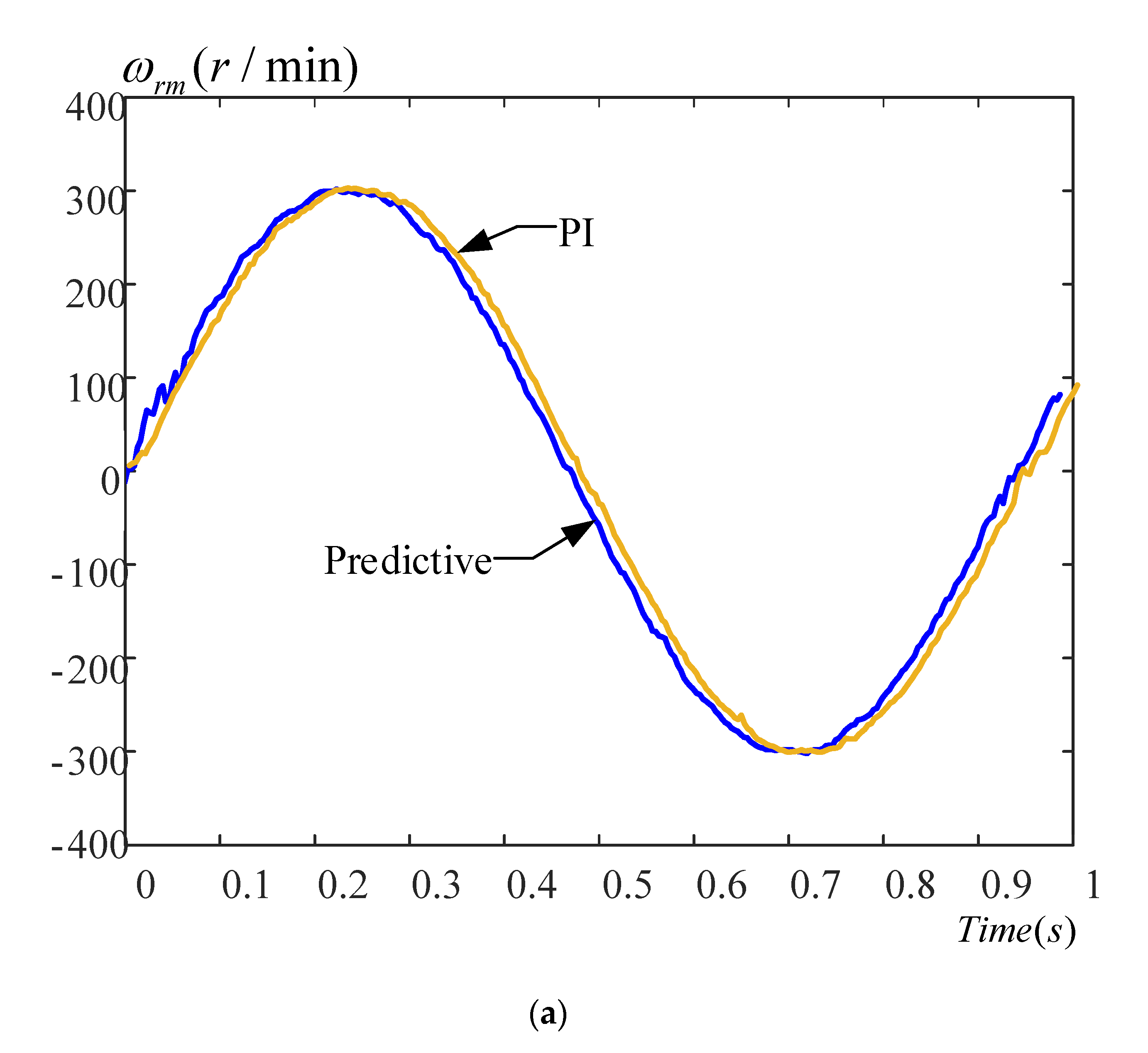
Figure 17a shows the measured speed responses of a sinusoidal speed command at
300 r/min. We can see that the predictive control can follow the speed commands well, but the PI control has lagging responses.
Figure 17b shows the speed errors, and we can see that the PI control has greater speed errors than the predictive control does.
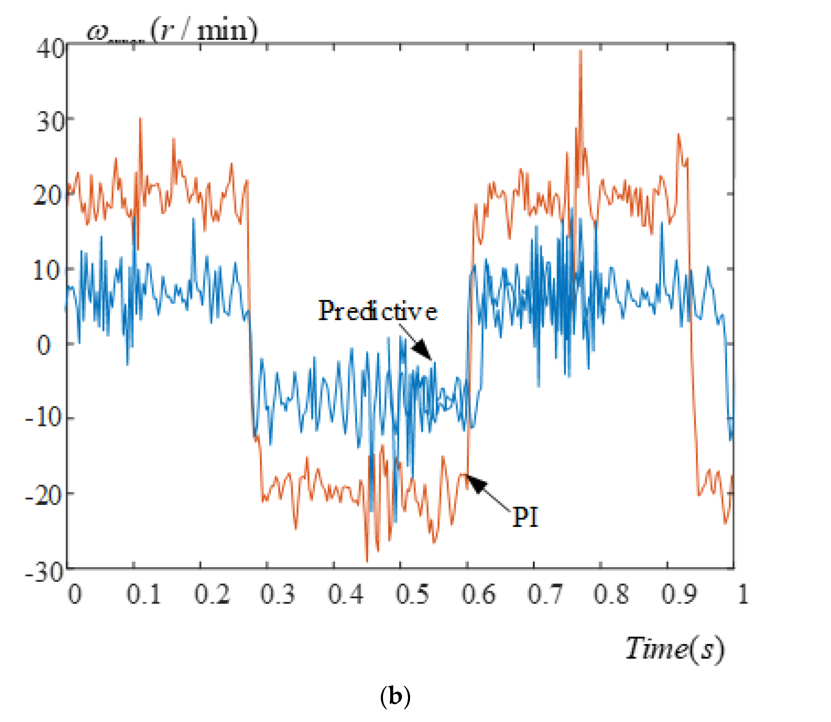
Figure 18a displays the measured speed responses of a triangular speed command at
300 r/min, and we can observe that the predictive control has a better tracking ability than the PI control does.
Figure 18b displays the speed tracking errors, and the predictive control provides
10 r/min tracking errors; however, the PI control has
20 r/min tracking errors. Thus, we can see that the predictive control has better performance than the PI control because the predictive control uses real-time optimization techniques. The PI control, however, uses integrational control, and this causes serious time delays. Generally speaking, in this paper, the speed errors in steady-state conditions are
r/min, and the current errors in the steady-state conditions are
Ampere. In addition, the THD of the a-phase, b-phase, and c-phase currents is near 6.5% when using the predictive control and active damping control.
7. Conclusions
In this paper, a high-order band-pass active damping controller is proposed to eliminate the input harmonic currents of small-film capacitor IPMSM drive systems. A systematic predictive constrained speed controller is designed to improve the transient, load disturbance, and tracking responses. Furthermore, a systematic predictive constrained current controller is used to reduce motor harmonic currents, in which a Lagrange multiplier is used to calculate the input constraints. After that, an optimization technique is employed to obtain the control input. A DSP, type TMS320F28035, manufactured by Texas Instruments, is used as a control center. Experimental results validate the theoretical analysis. Although the development of the predictive constrained control algorithms is complicated, the implementation of the predictive constrained control algorithms is very simple.
The proposed drive system in this paper has lower input harmonic currents and a better power factor than electrolytic capacitor DC-link inverters. In addition, this small-film DC-link capacitor drive system has a smaller size, a lower cost, and a longer life than traditional electrolytic capacitor DC-link IPMSM drive systems.


