Article

Numerical Simulation of the Cleaning Performance of a Venturi Scrubber

by
Haouari Khadra
1,
Rahmani Kouider
2,
Naas Toufik Tayeb
3,
Awf Al-Kassir
4 and
Juan Pablo Carrasco-Amador
4,*
1
LDMM Laboratory, Ziane Achour University of Djelfa, Djelfa 17000, Algeria
2
Research Laboratory Modeling Simulation and Optimization of Real Complex Systems, Djelfa 17000, Algeria
3
Gas Turbine Joint Research Team, Ziane Achour University of Djelfa, Djelfa 17000, Algeria
4
School of Industrial Engineering, University of Extremadura, 06006 Badajoz, Spain
*
Author to whom correspondence should be addressed.
Energies 2022, 15(4), 1531; https://doi.org/10.3390/en15041531
Submission received: 28 January 2022 / Revised: 11 February 2022 / Accepted: 14 February 2022 / Published: 18 February 2022
(This article belongs to the Special Issue Pyrolysis and Gasification of Biomass and Waste)

Abstract

:
Industrial applications need to use different systems for the problem of gas cleaning. A lot of processes have been developed, such as the use of a venturi for gas cleaning and pollution reduction. Additionally, several studies have been developed especially in terms of pressure drop because it is one of the main parameters to determine its efficiency. While the phenomenon of mass transfer in a venturi scrubber has not found much attention, in the present study, a mass transfer two-dimensional simulation is developed for gasification gas cleaning through a venturi scrubber with boundary conditions represented in air inlet velocities of 10, 15, and 20 m/s and water inlet mass flow of 0.02, 0.04 and 0.06 kg/s. In this work, Navier–Stokes equations are solved numerically and the mass transfer technique is treated by the volume of fluid (VOF) model, using CFD software. The obtained results were analyzed by presenting the mass fraction, velocity and pressure contours, and profiles. The probability density function (PDF) of mass transfer is studied too, showing how the removal efficiency of the venturi scrubber increases with a decrease in the liquid flow rate and an increase in the gas velocity. Therefore, the results show that the proposed venturi has the best mass transfer performance with a PDF that reaches 97.6 for velocity liquid of 20 m/s and the removal efficiency showed higher values at low liquid flow rates.

1. Introduction

It is important for the industry to clean the gas resulting from different processes. Therefore, to achieve this objective, a venturi shape is one of the most used devices because of its high efficiency in removing fine particles, its low cost, ease of maintenance, and its simple design.
The venturi consists of three principal sections: convergence, diffuser, and the throat. It also contains orifices for liquid introduction, which may be in the throat or before the convergence section. Venturi uses the high energy produced by accelerating the gas in the convergence section to break up the liquid into droplets in the throat. These droplets are responsible for cleaning the gas as they encapsulate and trap the particles [1,2].
Given the importance of venturi scrubbers, it has received a lot of interest from many mathematical and computational models that have been developed to study the parameters affecting venturi scrubbers. Lina [3] provided a study on the influence of venturi on the cleaning performance of elliptical filter cartridges. Sunuk et al. [4] proposed a thermal cyclic test device with a venturi injector designed to test a large number of samples rapidly. Kenneth [5] presented a paper based on Boll’s model containing a set of design charts and equations to give general solutions for estimating pressure drop in venturi devices. Kailash [2] investigated the performance evaluation of a venturi aeration system. Breitenmoser et al. [1] presented a model to predict the efficiency of droplet size distribution in a venturi scrubber with liquid film injection. Viswanathan [6] developed an annular flow model to predict the pressure drop in a venturi and considers venturi geometry, throat gas velocity, liquid-to-gas ratio, and liquid film flow rate. Through the integral momentum equation, Azzopardi [7] developed a model involving the growth of the boundary layer in the diffuser for a venturi to predict the pressure drop. Pulley et al. [8] extended the model by Azobardi to include the prediction of the efficiency of particle collection by a venturi scrubber. Ananthanarayanan et al. [9] tested a bi-dimensional simplified model, depending on the experimental data to predict collection efficiency and liquid flux distribution in a venturi scrubber, as well as the effect of throat gas velocity, liquid-to-gas ratio, aspect ratio, and nozzle diameter. Gonçalves et al. [10] evaluated the models available to predict pressure drop in a venturi by comparing the mathematical equations for these models with experimental data. Mohebbi developed a two-dimensional model based on the (Eulerian/Lagrangian) method to predict the efficiency of particle collection from the gas stream in the one- orifice venturi scrubber [11]. Sunand Azzopardi [12] extended the boundary layer model in the diffuser section to include a description of the boundary layer in the three venturi sections to predict the pressure loss for a venturi device of the type of Pearse–Anthony at high pressure. Viswanathan proposed an improved algorithm based on the prediction of minimum pressure drop prediction to improve venturi performance. It takes into account the design and operating parameters. This algorithm was applied cylindrical and rectangular venturi devices of the type of Pearse–Anthony [13]. Nasseh et al. [14] relied on the artificial neural network approach to predict the pressure drop in the venturi. He applied the design of three independent artificial neural networks using three data sets of five different venturi. Based on models of Clavert and Young, Alexia et al. [15] improved graphical tools to estimate the overall collection efficiency of venturi devices. Under the defined operating conditions and design, Kumar developed a mathematical model to study the drop in the Reynolds number effect on the small particle collection of a venturi scrubber [16]. An artificial neural network design was used by Taheri, based on a genetic algorithm, where he used experimental data to create these artificial neural networks to predict the collection efficiency of venturi scrubber [17]. Nasseh used neural networks to estimate the pressure loss in a venturi scrubber with an annular two-phase flow model, genetic algorithm, and artificial neural networks. He used experimental data for differently designed venturi devices, three injection systems, and different operating conditions for design these networks [18]. Shraiber et al. [19] developed a mathematical model that includes gas turbulence to study its effects on the aggregation efficiency in a venturi scrubber. To study the fluid mechanics of the two liquid and gas phases and their effect on the pressure drop in venturi, Guerra et al. [20] performed a three-dimensional simulation on a rectangular venturi used the VOF model and evaluated the influence of the number of the orifices on the distribution of the liquid in venturi. Ali et al. [21] performed a 3D simulation on a venturi scrubber based on Euler’s model by CFX and presented his work through three scientific papers. The first paper focused on lower pressures and studied the effect of the flow gas and static pressure rate in the liquid inlet. The second paper includes the evaluation of the pressure in the throat and the study of fluid dynamics in the venturi. The third paper contained the effect of gas and liquid flow rate on dust removal efficiency [22,23]. Toledo-Melchor et al. [24] performed a three-dimensional simulation of different gas flows on five venturi geometries, with a difference between them in the angles of convergence and divergence. Additionally, they studied the two-phase simulation of a single venturi geometry to analyze the behavior of gas flow and the effect of water flow on pressure drop. Luan et al. [25] achieved a 3D numerical simulation of the flow of tar gas inside a square venturi scrubber using ANSYS-fluent and compared contours of velocity, pressure, and the wall shear stress with a circular venturi scrubber. Qamar studied the effect of the number and location of holes on dust collection efficiency in the venturi through numerical simulations based on the Euler–Lagrange approach using ANSYS–CFX [26]. Manisha Balsimulated [27] proposed a three-dimensional flow fluid in a venturi scrubber by CFD to study the effects of throat gas velocity, liquid mass flow rate, and liquid-to-gas ratio on the pressure loss In this simulation, a Reynolds reorganization group (RNG), k–ε turbulence model, and the volume of the fluid model (VOF) were used. To examine the effect of the liquid-to-gas ratio on the collection efficiency of potassium oxide particles in a venturi, Safdar et al. [28] made a 3D simulation using CFX for different streams of gas and liquid. Few studies have been concerned with thermal and mass transfer in a venturi. Placek’s model for determining the particle collection efficiency of the venturi scrubber includes heat and mass transfer and analyzes the mechanisms of particle collection [29]. Taheri et al. [30] includes a 3D simulation of the absorption of SO2 based on a mathematical model. Additionally, they studied the mass transfer process assuming that the liquid was a mixture of droplets and film. Rahimi et al. [31,32] developed a one-dimensional model to analyze the effect of heat and mass transfer on the efficiency of venturi devices and the operating parameters’ effects on the phenomenon of heat and mass transfer. They presented another model by developing the equations governing the transfer of heat and mass between two stages. For the analysis of the laminar forced convection heat and mass transfer in a tube venturi with a wetted wall, Igo et al. [33,34] conducted a numerical simulation on the rectangular venturi, where he focused on the influences of the venturi effect, inlet Reynolds number, and venturi diameter ratio. He also studied the turbulent flow in a venturi by a two-dimensional simulation of air turbulent flow. This work aims to study the cleaning of the gas produced by the gasification of biomass in a venturi and mass transfer in a venturi scrubber. Many authors have studied the gasification process of biomass to produce a clean gas that is combustible for energy production, such as Al-Kassir et al. [35]. The use of biomass residues as non-pollutant fuels in combustion processes has an economical benefit as well as helping in the social development of rural zones as it decreases the environmental impact by eliminating the remnants and decreasing the emissions of pollutants to the atmosphere as deduced by Awf Al-Kassir et al. [36]. They developed a study on the drying and combustion of solid biomass residues and their combustion inside a boiler to produce clean combustible gas.
Due to the difficulty of cleaning the gas resulting from industrial applications, the venturi shape is one of the most used devices because of its high efficiency in removing fine particles, its low cost, ease of maintenance, and its simple design. Therefore, this paper aims to improve the high mass transfer and cleaning performance for the gasification of biomass fluid inside a new venturi scrubber. Various gas velocities with different mass flow liquid are proposed to investigate the flow formation and mass fraction characteristics within the suggested venturi. The important energy efficiency and removal efficiency of the venturi system are also appraised.

2. Geometry Details and Modeling

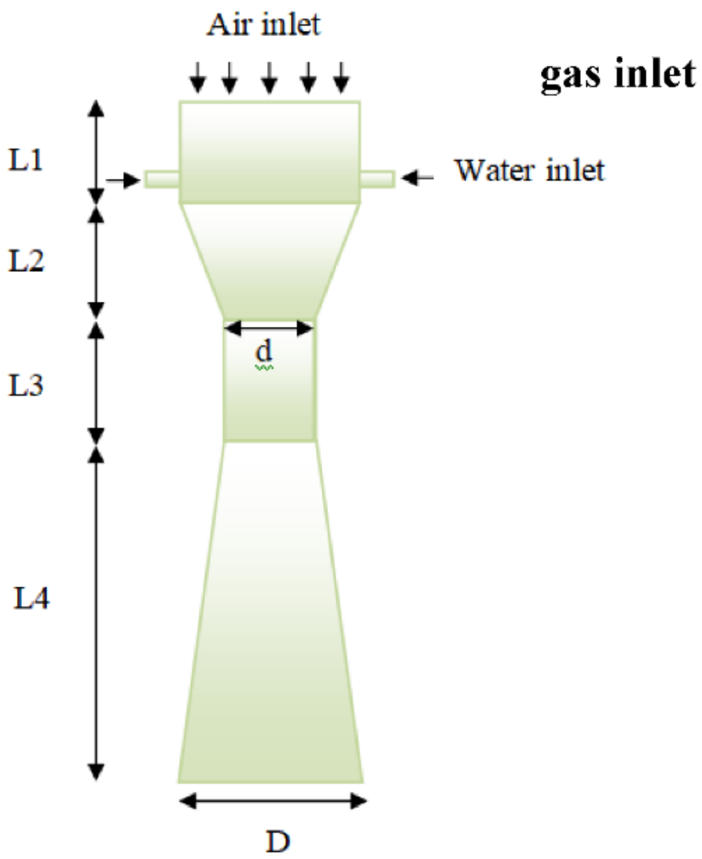
2.1. Geometry Description

Figure 1 presents the 2D geometry utilized in this work. The venturi geometry consists of a convergent and a diffuser section with a diameter of 0.075 m, and a throat section with a diameter of 0.027 m. The length of the convergent section, diffuser, and throat are 0.13, 0.34, 0.165 m, respectively (as show in Table 1).
The boundary conditions are to impose a velocity of the gas on the gas inlet with a volumetric fraction equal to zero; the velocity of the liquid at the liquid inlet with a volumetric fraction equals one, and the static pressure at outlet equal zero. A no-slip velocity condition was applied at the wall surfaces.

2.2. Properties of Gas

Table 2 includes the properties of the gas produced by the gasification of biomass used in this study [37].

2.3. Governing Equations

The continuity, momentum, diffusion, and species transfer equations that express the governing equations for Newtonian, incompressible, and immiscible flows are defined as follows [1,2]:
u = 0
ρ u t + ρ u u = p + μ 2 u + ρ g
c i t + c i u = D i 2 c
ρ is the total density, t is the time, p is the pressure, g is the gravitational acceleration, D i is the species mass diffusivity, and c i is molar concentration.
The pressure drop must be taken into account with the removal efficiency and the flow rate when evaluating the overall performances of the cleaning venturi reliability. For this, it is important to present the removal energy cost “REC”, which is expressed by:
R E C = Q × Δ p E R
The removal efficiency is determined from the following equation:
E R = C i n C 0 C i n
where Q is the flow rate (m3/s), Δ p is the pressure drop along the venturi, E R is the removal efficiency of the proposed venturi, and C is the mass fraction of water.

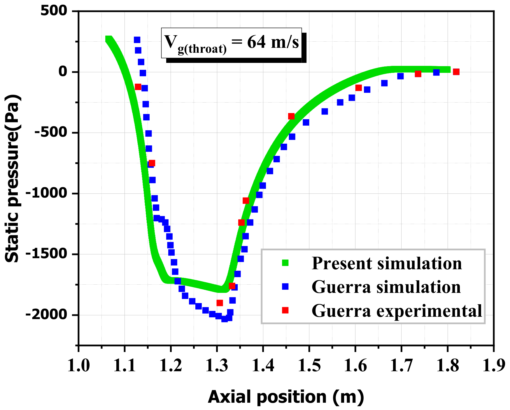
3. Meshing Study and Validation

The grid independency has an essential role in simulating CFD to obtain approximate results. So, choosing the best network is very important. Four different meshes were identified for simulation. The nodes number in these models is as follows: 13,557, 31,345, 81,938 and 144,696. The simulation in these models had a velocity gas of 20 m/s, and the mass flow is 0.02 kg/s. The velocity variations were evaluated for increasing nodes, as shown in Figure 2. As we noted, there is no significant difference between the different mesh results. As a result, the mesh with 81,938 nodes was adopted as a suitable mesh for investigation.
Numerical simulations of air and water flow in the venturi scrubber were performed using a CFD code. The multiphase flow is processed using the VOF model. The solutions in this simulation were to use the explicit schema for time estimation. The PISO algorithm for pressure, velocity coupling, and PRESTO pressure diagram were applied. The second-order upwind scheme was used for the discretization momentum equations.
In order to evaluate and ensure the CFD accuracy, a quantitative validation with the results obtained by Silva et al. [38] was performed; the results show a gas velocity along the venturi, for the case of mass flow rate, of 0.075 kg/s. The comparison is satisfactory and revealed good agreements among the results, as shown in Figure 3.
Another validation was performed for a gas–liquid flow simulation in a venturi scrubber at a velocity of 64 m/s and compared to the simulations and experimental work conducted by Guerra et al. [20]. The results that were compared were the static pressure behavior of the venturi. The simulation results were satisfactory (as shown in Figure 4).

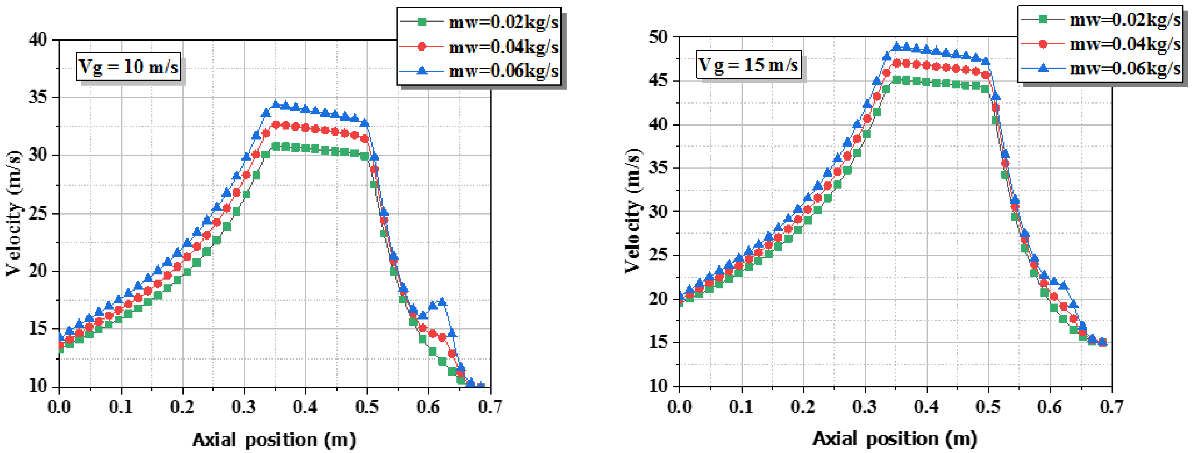
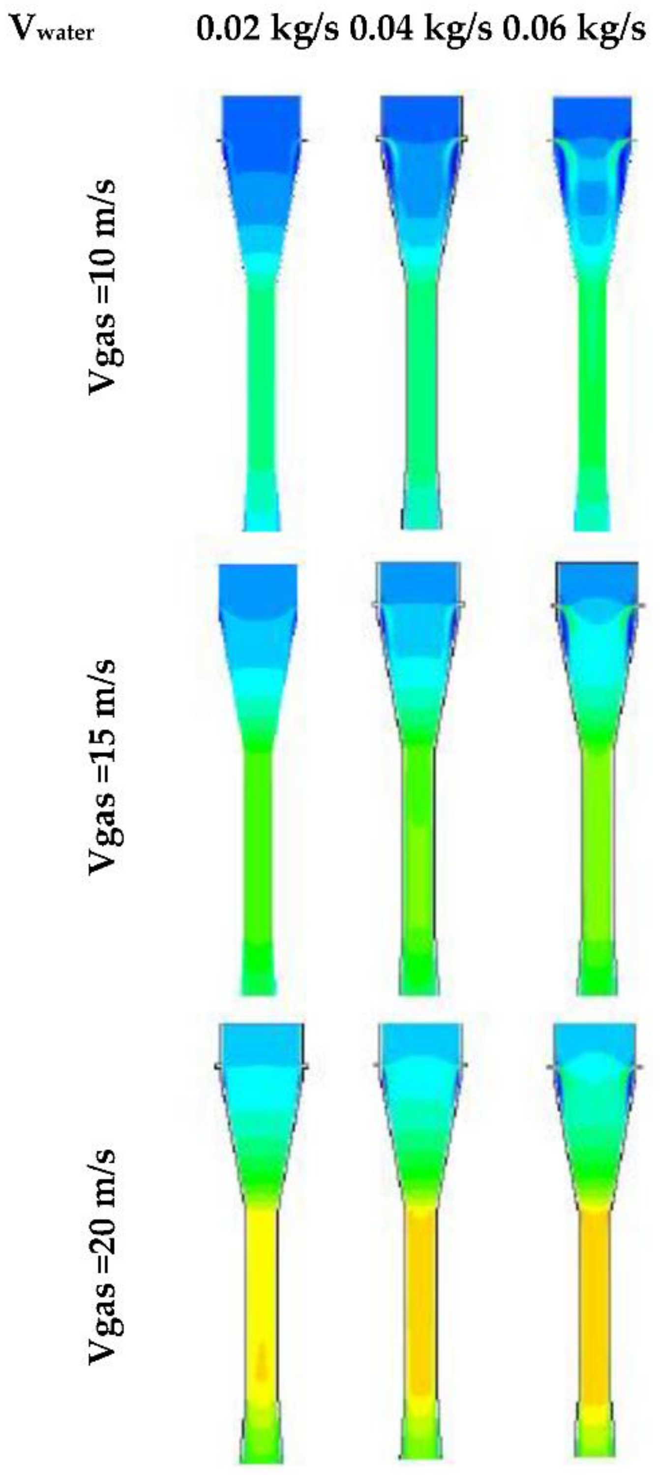
4. Results and Discussions

Pressure, velocity, and mass fraction are the most important parameters in the evaluation of the performance of a venturi scrubber. In this study, a numerical simulation of a venturi cleaning flow using CFD code was conducted. The simulation results depended on the boundary conditions, represented in gas velocities of 10, 15, and 20 m/s and mass flow liquid values of 0.02, 0.04, and 0.06 kg/s.
Figure 5 shows the velocity evolution in the venturi as a function of the change in inlet gas velocity and constant inlet water mass flow equal to 0.06 kg/s. The three curves have the same behavior. In the range from 0.7 to 0.5, we noticed an increase in the velocity until it arrived at the water inlet. Then, it decreases because there is a contraction in the airway at the water inlet. The velocity increases in the range converging section from 0.7 to 0.6 m/s due to the section diameter change according to the principle of mass continuity. In addition, it continues to increase until it arrives at its maximum value in the field from 0.5 to 0.35 m/s, due to the friction between the maximum fluid velocity and the wall in the throat section. We noticed the decrease in velocity in the diffuser range from 0.35 to 0 m/s because of the change in the section diameter.
Figure 6 and Figure 7 represent the contours and the graphs of the velocity of flow multiphase in venture scrubber at gas velocities inlet of 10, 15, and 20 m/s and at inlet water mass flow values of 0.02, 0.04, and 0.06 kg/s. We observed that the increase in inlet velocity influences the velocity development in the venturi scrubbers. The velocity reaches 30.81, 32.67, and 34.36 m/s at a gas inlet velocity of 10 m/s, at an inlet water mass flow of 0.02, 0.04, and 0.06 kg/s, respectively. It reaches 45.08, 47.04, and 48.84 m/s at a gas inlet velocity of 15 m/s, at an inlet water mass flow of 0.02, 0.04, and 0.06 kg/s, respectively. It reaches at 59.33, 61.3, and 63.22 m/s at a gas inlet velocity of 20 m/s, at an inlet water mass flow of 0.02, 0.04, and 0.06 kg/s, respectively.
Figure 8 indicates the contour of static pressure in the venturi. The static pressure is high at the beginning of the venturi. It begins to decrease in the convergent section due to the conversion of static pressure into kinetic energy. There is a sharp drop of static pressure due to friction in the throat. Part of the pressure is recovered in the diffuser due to the conversion of kinetic energy into pressure.
The results of the comparison of static pressure with mass flow difference for inlet water mass flow and static gas velocity inlet are represented in Figure 9, where we note that, at the gas velocity inlet of 10 m/s and the inlet water mass flow 0.02, 0.04, and 0.06 kg/s, the static pressure approximate values at the beginning of the venturi were 93.29, 109.06, and 117.96 (Pa), respectively. The minimum value of static pressure at the throat is approximately −606.73 Pa for the three mass flows at the water inlet. For air velocity inlet of 15 m/s and the inlet water mass flow 0.02, 0.04, and 0.06 kg/s, the static pressure approximate values at the beginning of the venturi were 182.84, 210.03, and 231.48 (Pa), respectively. The minimum value of static pressure at the throat was approximately −1239.73 Pa for the three velocities of water at the inlet. Additionally, for gas velocity inlet of 20 m/s and the inlet water mass flow 0.02, 0.04, and 0.06 kg/s, the static pressure approximate values at the beginning of the venturi were 298.69, 335.22, and 369.14 (Pa), respectively. The minimum value of static pressure at the throat was approximately −2097.18 Pa for the three velocities of water at the inlet.
Figure 10 includes a comparison of dynamic pressure results with the velocity difference of water velocity inlet and a constant air velocity inlet. Through the curves, we noticed that the dynamic pressure behaves the same as velocity because its value is related to the square of velocity. The dynamic pressure also increases with the increase in velocity water inlet. The contour of dynamic pressure is shown in Figure 11. The dynamic pressure increases in the convergent section and arrives at its high values in the throat. In the diffuser section, the dynamic pressure decreases.
The mass fraction of the water contour represents in Figure 12. In all cases, the mass fraction is high at the water inlet, especially with the mass flow water inlet 0.06 kg/s, then concentrates on the wall under the influence of the high velocity of the gas.
Figure 13 illustrates the mass transfer for different inlet water velocity cases at the throat of the venturi. It has been observed that the mass fraction is more enhanced with the increase in water velocity in the throat section of the venturi scrubber for all cases of inlet gas flows. The mass fraction of gas downstream of orifices gradually reduces because of scrubbing water solution entering from orifices. This increases the importance of the proposed venturi efficiency.
Figure 14 expresses the probability density function for the volume fraction of water with the velocity difference of water mass flow inlet and a constant air velocity inlet in a venturi. We see that the large percentages of PDF were with a volume fraction of less than 0.1 for all cases. This result indicates that the mass transfer in the venturi scrubber is weak.
Figure 15 expresses the pressure drop values for the four mass flow rates. We note that the highest value of the pressure drop is approximately 1600 Pa with the highest rate of liquid flow.
Figure 16 shows the difference in removal efficiency at different mass flow rates. It has been observed that the removal efficiency of the venturi scrubber increases with a decrease in the liquid flow rate and an increase in the gas velocity.
Figure 17 illustrates the evolution of the cost of removal energy of the venturi system for various cases of inlet mass flow rates. As can be seen, the REC increases with the increase in the inlet water flow rate and increase in gas velocity.

5. Conclusions

We investigated the performance of the best venturi efficiency for a gas generated from biomass gasifiers. The results achieved are relevant in industrial systems. Through the results, we can conclude that:
-
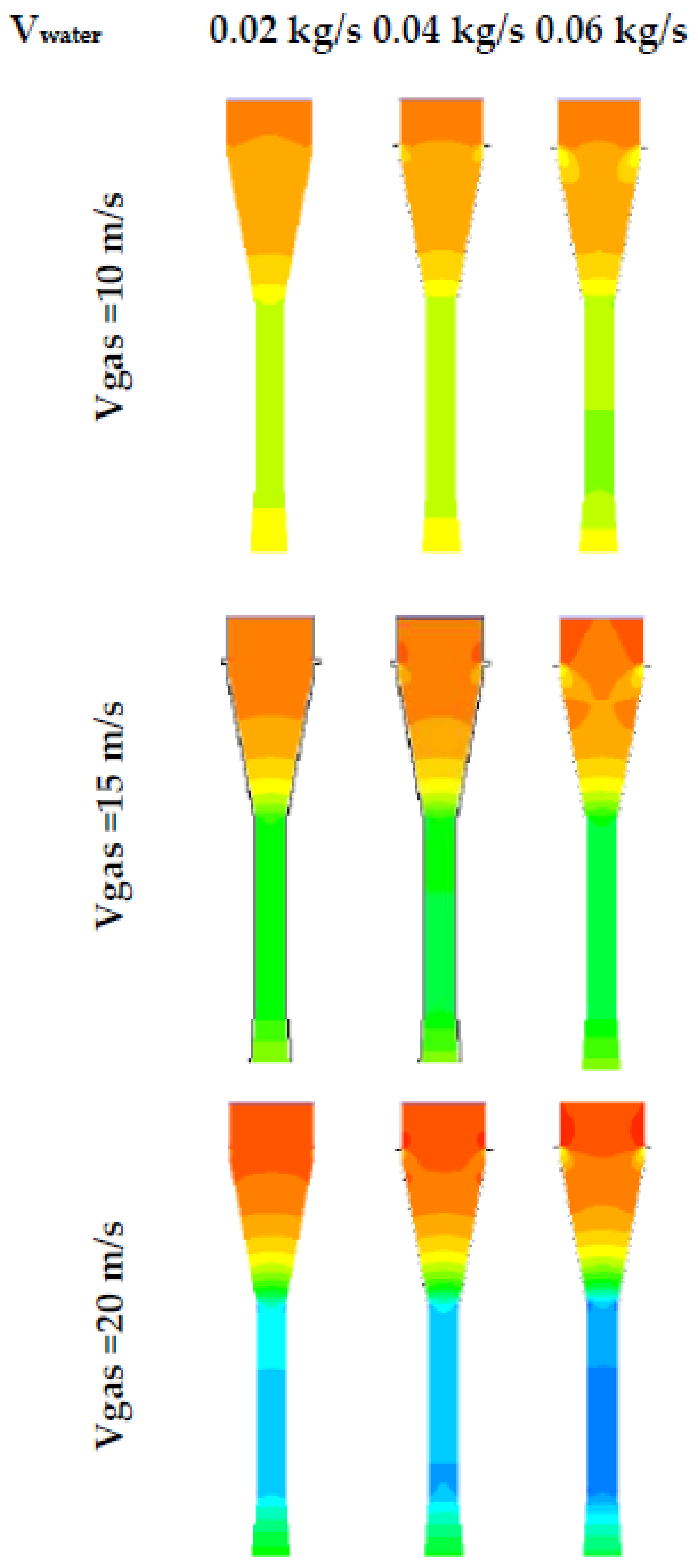
The liquid flow affects the velocity as the velocity increases with the increase in the liquid flow with the same velocity of the air.
-
The dynamic has the same behavior velocity, with decreases with the increase in gas velocity and water velocity at inlets.
-
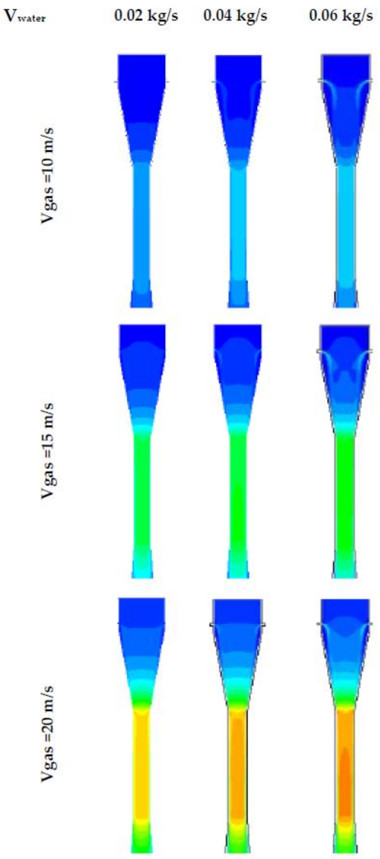
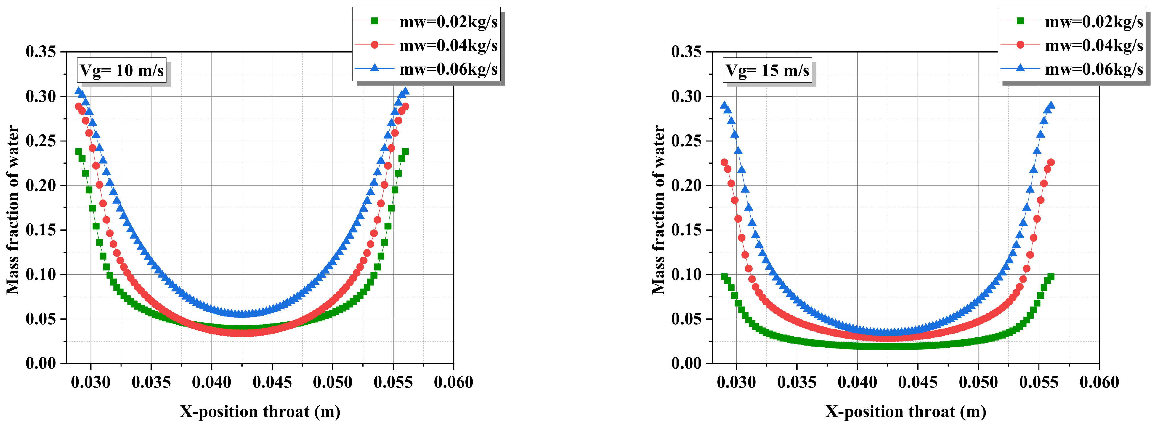
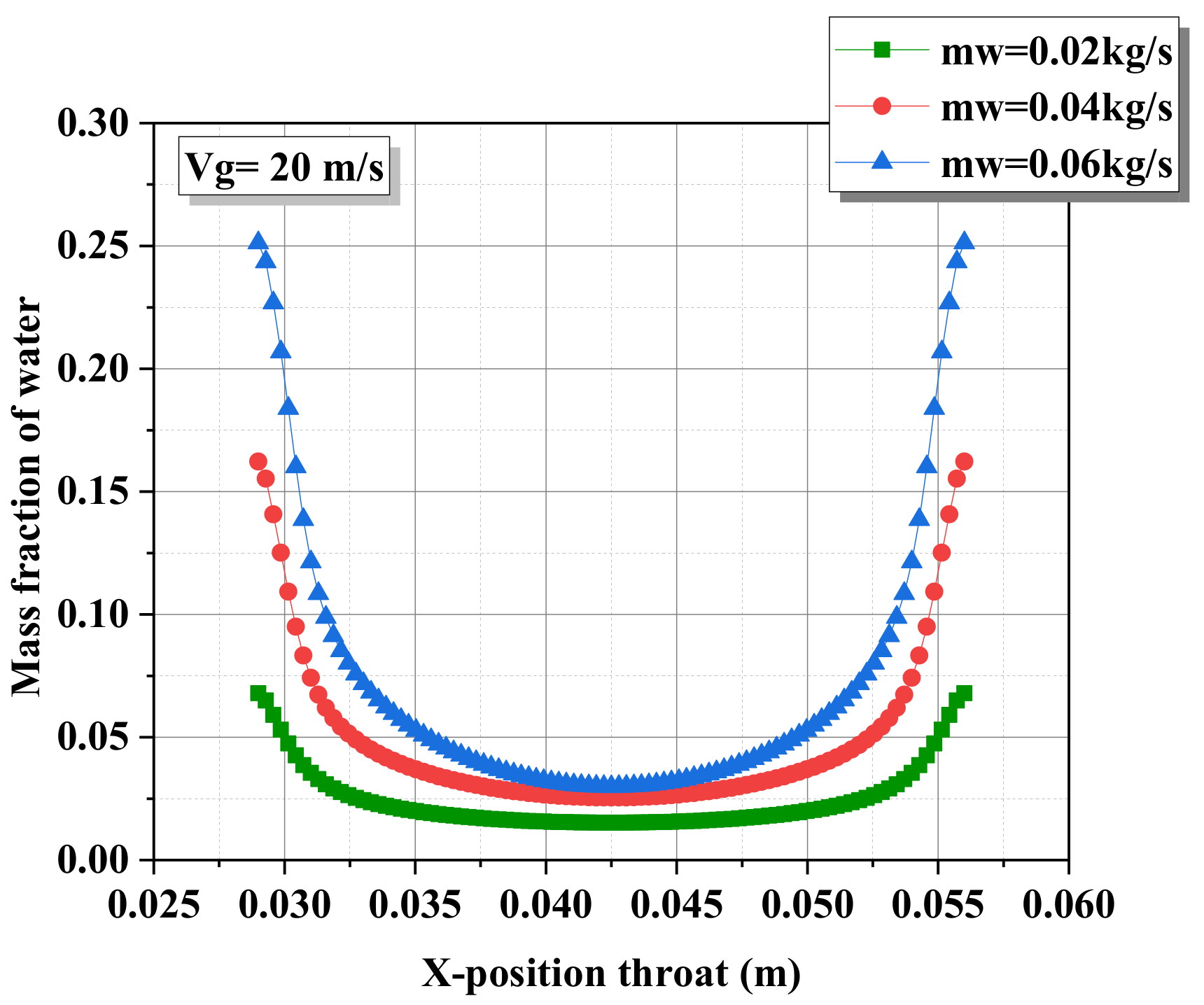
The mass fraction of the water concentrates on the wall under the influence of the high velocity of the gas.
-
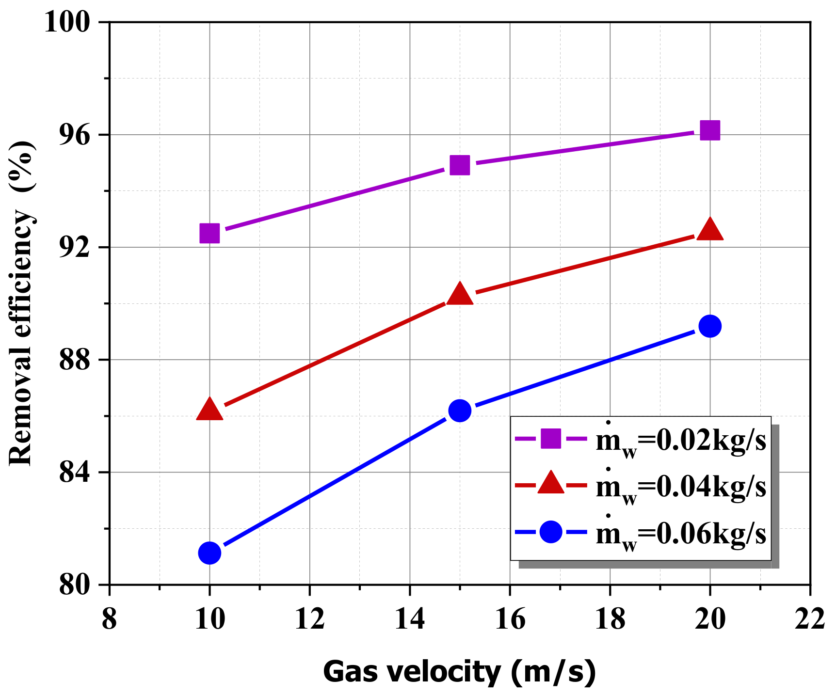
The removal efficiency of the venturi scrubber increases with a decrease in the liquid flow rate and an increase in the gas velocity.
-
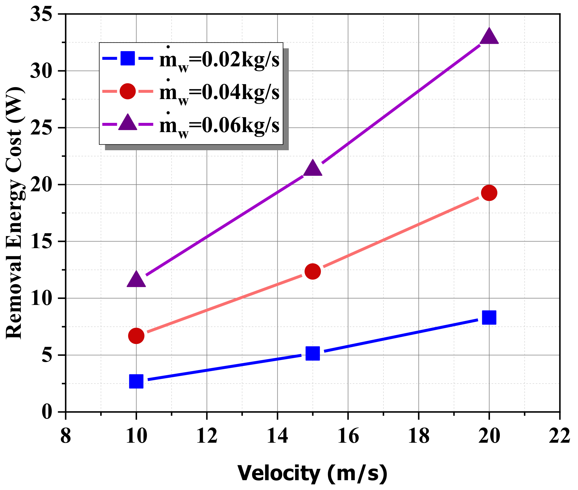
The REC increases with the increase in the inlet water flow rate and increase in gas velocity.
We propose these suggestions as future work:
-
The investigation of the mass transfer through a three-dimensional simulation of the cleaning of the gas produced by the gasification of biomass.
-
The creation of a in new venturi scrubber with different boundary conditions to enhance further the energy efficiency.
-
The study of the influence of the venturi on the cleaning performance of nano systems.

Author Contributions

Conceptualization, H.K., R.K., N.T.T. and A.A.-K.; Investigation, H.K., R.K., N.T.T. and A.A.-K.; Supervision, J.P.C.-A.; Writing—original draft, H.K., R.K. and N.T.T.; Writing—review and editing, J.P.C.-A. All authors have read and agreed to the published version of the manuscript.

Funding

This research received no external funding.

Institutional Review Board Statement

This study did not require ethical approval.

Informed Consent Statement

Not applicable.

Data Availability Statement

Not applicable.

Conflicts of Interest

The authors declare no conflict of interest.

References

  1. Breitenmoser, D.; Papadopoulos, P.; Lind, T.; Prasser, H.M. Droplet size distribution in a full-scale rectangular self-priming Venturi scrubber with liquid film injection. Int. J. Multiph. Flow 2021, 142, 103694. [Google Scholar] [CrossRef]
  2. Yadav, A.; Kumar, A.; Sarkar, S. Performance evaluation of venturi aeration system. Aquac. Eng. 2021, 93, 102156. [Google Scholar] [CrossRef]
  3. Lin, L.; Liu, T.; Yuan, N.; Xu, Z.; Chen, H. Study on the influence of venturi on the cleaning performance of elliptical filter cartridge. Powder Technol. 2021, 377, 139–148. [Google Scholar] [CrossRef]
  4. Kim, S.; Shin, D.H.; Jung, Y.; Ko, H.S.; Shin, Y. Short-period thermal cyclic test device for large volumes of microencapsulated phase change materials using a Venturi injector. J. Energy Storage 2021, 43, 103223. [Google Scholar] [CrossRef]
  5. Hollands, K.G.; Goel, K.C. A General Method for Predicting Pressure Loss in Venturi Scrubbers. Ind. Eng. Chem. Fundam. 1975, 14, 16–22. [Google Scholar] [CrossRef]
  6. Viswanathan, S.; Gnyp, A.W.; St Pierre, C.C. Annular Flow Pressure Drop Model for Pease-Anthony-Type Venturi Scrubbers. AIChE J. 1985, 31, 1947–1958. [Google Scholar] [CrossRef]
  7. Azzopardi, B.J.; Teixeira SF, C.F.; Govan, A.H.; Bott, T.R. Improved model for pressure drop in Venturi scrubbers. Process Saf. Environ. Prot. 1991, 69, 237–245. [Google Scholar]
  8. Pulley, R.A. Modelling the performance of venturi scrubbers. Chem. Eng. J. 1997, 67, 9–18. [Google Scholar] [CrossRef]
  9. Ananthanarayanan, N.V.; Viswanathan, S. Estimating Maximum Removal Efficiency in Venturi Scrubbers. Environ. Energy Eng. 1998, 44, 2549–2560. [Google Scholar] [CrossRef]
  10. Gonçalves, J.A.S.; Alonso, D.F.; Costa, M.A.M.; Azzopardi, B.J.; Coury, J.R. Evaluation of the models available for the prediction of pressure drop in venturi scrubbers. J. Hazard. Mater. 2001, 81, 123–140. [Google Scholar] [CrossRef]
  11. Mohebbi, A.; Taheri, M.; Fathikaljahi, J.; Talaie, M.R. Simulation of an orifice scrubber performance based on Eulerian/Lagrangian method. J. Hazard. Mater. 2003, 100, 13–25. [Google Scholar] [CrossRef]
  12. Sun, H.; Azzopardi, B.J. Modelling gas-liquid flow in Venturi scrubbers at high pressure. Process Saf. Environ. Prot. Trans. Inst. Chem. Eng. Part B 2003, 81, 250–256. [Google Scholar] [CrossRef]
  13. Viswanathan, S.; Ananthanarayanan, N.V.; Azzopardi, B.J. Venturi Scrubber Modelling and Optimization. Can. J. Chem. Eng. 2005, 83, 194–203. [Google Scholar] [CrossRef]
  14. Nasseh, S.; Mohebbi, A.; Jeirani, Z.; Sarrafi, A. Predicting pressure drop in venturi scrubbers with artificial neural networks. J. Hazard. Mater. 2007, 143, 144–149. [Google Scholar] [CrossRef]
  15. Taylor, P.; Economopoulou, A.A.; Harrison, R.M.; Economopoulou, A.A.; Harrison, R.M. Aerosol Science and Technology Graphical Analysis of the Performance of Venturi Scrubbers for Particle Abatement. Part I: Rapid Collection Efficiency Evaluation Graphical Analysis of the Performance of Venturi Scrubbers for Particle Abatement. Part I. Aerosol Sci. Technol. 2007, 41, 37–41. [Google Scholar] [CrossRef]
  16. Kumar, A.; Kumar, P.; Singal, S.K. Performance of A Venturi Scrubbers in Intermediate Drop Reynolds Number Regime for Small Particles at Different Throat Length and Throat Gas Velocity. Asian J. Water Environ. Pollut. 2008, 6, 7–13. [Google Scholar]
  17. Taheri, M.; Mohebbi, A. Design of artificial neural networks using a genetic algorithm to predict collection efficiency in venturi scrubbers. J. Hazard. Mater. 2008, 157, 122–129. [Google Scholar] [CrossRef]
  18. Nasseh, S.; Mohebbi, A.; Sarrafi, A.; Taheri, M. Estimation of pressure drop in venturi scrubbers based on annular two-phase flow model, artificial neural networks and genetic algorithm. Chem. Eng. J. 2009, 150, 131–138. [Google Scholar] [CrossRef]
  19. Shraiber, A.A.; Fedinchik, I.V.; Protasov, M.V. On effect of gas flow turbulence on the efficiency of particle collection in a Venturi scrubber. High Temp. 2015, 53, 80–85. [Google Scholar] [CrossRef]
  20. Guerra, V.G.; Béttega, R.; Gonçalves, J.A.S.; Coury, J.R. Pressure drop and liquid distribution in a venturi scrubber: Experimental data and CFD simulation. Ind. Eng. Chem. Res. 2012, 51, 8049–8060. [Google Scholar] [CrossRef]
  21. Ali, M.; Changqi, Y.; Zhongning, S.; Jianjun, W.; Mehboob, K. CFD Simulation of Prediction of Pressure Drop in Venturi Scrubber. Appl. Mech. Mater. 2012, 169, 3008–3011. [Google Scholar] [CrossRef]
  22. Mechanics, A. CFD Simulation of Throat Pressure in Venturi Scrubber Majid Ali. Appl. Mech. Mater. 2012, 173, 3630–3634. [Google Scholar] [CrossRef]
  23. Ali, M.; Yan, C.; Sun, Z.; Wang, J.; Gu, H. CFD simulation of dust particle removal efficiency of a venturi scrubber in CFX. Nucl. Eng. Des. 2013, 256, 169–177. [Google Scholar] [CrossRef]
  24. Toledo-Melchor, M.M.; Gutiérrez-Torres, C.D.C.; Jiménez-Bernal, J.A.; Barbosa-Saldaña, J.G.; Martínez-Delgadillo, S.A.; de Leon, H.R.M.P.; Yoguéz-Seoane, A.; Alonzo-García, A. Numerical simulation of flow behavior within a venturi scrubber. Math. Probl. Eng. 2014, 2014, 106329. [Google Scholar] [CrossRef] [Green Version]
  25. Luan, Z.; Liu, X.; Zheng, M.; Zhu, L. Numerical Simulation of Square Section Venturi Scrubber with Horizontal Spray. Procedia Comput. Sci. 2017, 107, 117–121. [Google Scholar] [CrossRef]
  26. Qamar, S.A.; Sohail, A.; Qureshi, K.; Shah, A.; Irfan, N. Dust particle collection efficiency of venturi scrubber with varying number of orifices using CFX. In Proceedings of the ICET 2016, 2016 International Conference on Emerging Technologies (ICET), Islamabad, Pakistan, 18–19 October 2016. [Google Scholar] [CrossRef]
  27. Bal, M.; Meikap, B.C. Prediction of hydrodynamic characteristics of a venturi scrubber by using CFD simulation. S. Afr. J. Chem. Eng. 2017, 24, 222–231. [Google Scholar] [CrossRef]
  28. Safdar, I.; Khan, A.; Ali, M.; Mushtaq, A. Numerical Simulation of Particulate Removal Efficiency in Venturi Scrubber; IEEE: New York, NY, USA, 2017; pp. 1–6. [Google Scholar]
  29. Placek, T.D.; Peters, L.K. Analysis of particulate removal in venturi scrubbers—role of heat and mass transfer. AIChE J. 1982, 28, 31–39. [Google Scholar] [CrossRef]
  30. Taheri, M.; Mohebbi, A.; Taheri, A. Simulation of SO2 absorption in a venturi scrubber. Chem. Eng. Commun. 2010, 197, 934–952. [Google Scholar] [CrossRef]
  31. Rahimi, A.; Bakhshi, A. A Simple One-Dimensional Model for Investigation of Heat and Mass Transfer Effects on Removal Efficiency of Particulate Matters in a Venturi Scrubber. Iran. J. Chem. Eng. 2009, 6, 3–14. Available online: http://en.journals.sid.ir/ViewPaper.aspx?ID=170228 (accessed on 15 July 2021).
  32. Rahimi, A.; Niksiar, A.; Mobasheri, M. Considering roles of heat and mass transfer for increasing the ability of pressure drop models in venturi scrubbers. Chem. Eng. Process. Process Intensif. 2011, 50, 104–112. [Google Scholar] [CrossRef]
  33. Igo, S.W.; Bathiébo, D.J.; Palm, K.; N’Wuitcha, K.; Zeghmati, B.; Chesneau, X. Laminar forced convection heat and mass transfer in a venturi tube with wetted walls. Front. Heat Mass Transf. 2011, 2, 1–7. [Google Scholar] [CrossRef] [Green Version]
  34. Igo, S.W.; Kokou, N.; Palm, K.; Mihaescu, L.; Bathiébo, D.J. Numerical simulation of turbulent forced convection in a venturi channel with fully developed flow at the inlet Numerical simulation of turbulent forced convection in a venturi channel with fully developed flow at the inlet. Adv. Appl. Sci. Res. 2015, 5, 359–367. [Google Scholar]
  35. Al-Kassir, A.; Gañán-Gómez, J.; Mohamad, A.; Cuerda-Correa, E.M. A study of energy production from cork residues: Sawdust, sandpaper dust and triturated wood. Energy 2010, 35, 382–386. [Google Scholar] [CrossRef]
  36. Al-Kassir, A.; Coelho, P.; García-Sanz-Calcedo, J.; Moral, F.J.; Al-Karany, R.K.; Yusaf, T. An Experimental Technology of Drying and Clean Combustion of Biomass Residues. Appl. Sci. 2018, 8, 905. [Google Scholar] [CrossRef] [Green Version]
  37. Kumararaja, L. Modelling equations for the properties of producer gas generated from biomass gasifiers. Int. J. Appl. Math. Sci. 2016, 9, 103–112. [Google Scholar]
  38. Silva, A.M. Numerical and Experimental Study of Venturi Scrubbers. Ph.D. Thesis, Instituto Politécnico de Viana do Castelo, Viana Do Castelo, Portugal, December 2008. [Google Scholar]
Figure 1. Geometry description of the venturi scrubber.
Energies 15 01531 g001
Figure 2. Results of the various meshes: (A) single phase (gas), and (B) two phases (gas–water).
Energies 15 01531 g002
Figure 3. Results validation of the velocity in the venturi.
Energies 15 01531 g003
Figure 4. Quantitative validation of the static pressure in a venturi with Guerra et al. [20].
Energies 15 01531 g004
Figure 5. Evolution of velocity in the venturi scrubber.
Energies 15 01531 g005
Figure 6. Velocity profiles as a function of different inlet water velocities at the middle vertical line of the venturi.
Energies 15 01531 g006aEnergies 15 01531 g006b
Figure 7. Contours of velocity magnitude.
Energies 15 01531 g007
Figure 8. Contours of static pressure.
Energies 15 01531 g008
Figure 9. Comparison of the static pressure with various water velocities.
Energies 15 01531 g009
Figure 10. Comparison of the dynamic pressure with various water velocities.
Energies 15 01531 g010aEnergies 15 01531 g010b
Figure 11. Contours of the dynamic pressure.
Energies 15 01531 g011
Figure 12. Contours of water volume fraction.
Energies 15 01531 g012
Figure 13. Mass fraction at the X position in the throat of the venturi.
Energies 15 01531 g013aEnergies 15 01531 g013b
Figure 14. PDF of mass fraction with different mass flows of water.
Energies 15 01531 g014
Figure 15. Values of pressure drop with different mass flow rates of water in the venturi scrubber.
Energies 15 01531 g015
Figure 16. Removal efficiency of the venturi system at different fluid flow rates.
Energies 15 01531 g016
Figure 17. Removal efficiency cost of the venturi system at different fluid flow rates.
Energies 15 01531 g017
Table 1. Physical characteristics of the venturi.
Physical Characteristics of the Venturi
Converge diameterD (m)0.075
Diffuser diameter D (m)0.075
Throat diameter d (m)0.027
Length L1 (m)0.05
Length L2 (m)0.13
Length L3 (m)0.165
Length L4 (m)0.34
Orifice (m)0.001
Table 2. Properties of the gas.
Properties of the Gas
Density 1.03   kg / m 3
Molar specific heat capacity22.05 kJ/(kmol·K)
Molar mass25.14 kg/kmol
Viscosity 1.57263   ×   10 5 kg/(m·s)
Thermal conductivity0.0344 W/(m·K)
Diffusion coefficient 0.209   ×   10 4   m 2 /s
Publisher’s Note: MDPI stays neutral with regard to jurisdictional claims in published maps and institutional affiliations.

