Article

Experiment and Numerical Analysis of Thermal Performance of a Billboard External Receiver

1
School of Chemical Engineering and Technology, Xi’an Jiaotong University, Xi’an 710049, China
2
Department of Mechanical Engineering, Khwaja Fareed University of Engineering and Information Technology, Rahim Yar Khan 64200, Pakistan
3
School of Mechanical and Electrical Engineering, Xi’an Polytechnic University, Xi’an 710048, China
4
School of Energy and Architecture Engineering, Xi’an Aeronautical Institute, Xi’an 710077, China
5
U.S.-Pakistan Center for Advanced Studies in Energy, National University of Science and Technology, Islamabad 44000, Pakistan
*
Author to whom correspondence should be addressed.
Energies 2022, 15(6), 2188; https://doi.org/10.3390/en15062188
Submission received: 21 February 2022 / Revised: 8 March 2022 / Accepted: 15 March 2022 / Published: 17 March 2022
(This article belongs to the Topic Solar Thermal Energy and Photovoltaic Systems)

Abstract

:
The receiver serves as a critical component in tower-type concentrated solar power plants. Responsible for light-heat conversion, the efficiency of the receiver significantly affects the overall performance of the power plant. In the current study, the thermal performance of external receivers was investigated. An experiment was set up similarly using the solar simulator to experimentally investigate the heat losses of a billboard receiver. A billboard-type external receiver was designed, fabricated, and experimented with. A solar simulator having seven xenon lamps characteristics similar to the sunlight spectrum was used to obtain heat flux at the surface of the receiver. Convection losses in the head-on wind direction were evaluated, along with the radiation losses. The thermal efficiency of the billboard receiver calculated experimentally was around 83.9%. Numerical simulations were also carried out to compare the results against the experimental data. A variation of ±5% observed between both results validate the model proposed in the current study.

1. Introduction

The solar receivers serve as the fundamental component in tower-type CSP plants. Their function is to absorb solar heat flux reflecting from a heliostat field and transfer the absorbed heat to the Heat Transfer Fluid (HTF). Solar receiver plays a crucial role in Concentrated Solar Power (CSP) plants that affects the power plants’ efficiency. Based on their geometric shapes, the solar receivers are categorized into two types, i.e., (1) cavity receivers, (2) external receivers. Both shapes have been utilized in the actual power plants, although the research on the cavity receivers is more extensive than on the external receivers.
At first, a large-sized cubical-shaped cavity receiver was analytically modeled by Sandia laboratories [1], using heat transfer coefficients (HTC) for heat transmission within the receiver by employing the standardized semi-empirical formulations as well as the heat transferred through air flowing out of the aperture. The results were later verified against experiments [2]. Similarly, Koenig & Marvin [3] investigated a heat loss model at very high temperatures up to 550–900 °C for the cavity receiver surface and put forward an empirical correlation. Le Quere et al. [4] performed numerical formulations and carried out experiments to evaluate natural convection losses on a cubical-shaped cavity receiver having isothermal side panels. Their results depict that the convective losses are highly influenced by the inclination. James & Terry [5] examined five geometries of the cavity receivers including cylinder, sphere, elliptical, conical & hetero-conical to gauge the thermal performance of the receivers. They attained significant trends on the power profile of the receiver as well as the rim angle disparity of the concentrator, without any substantial effect on the receiver’s performance.
During a series of experiments, Kraabel [6] found natural convection losses by electrically heating the cavity receiver to achieve the desired temperature. In subsequent studies [7], radiant losses were also evaluated directly, and correlations were presented as a function of average Nusselt number dependent on Grashoff number and other geometric parameters of the cavity receivers including receiver’s length and height. McMordie et al. [8] also performed an experiment on the cavity receiver and evaluated heat losses via radiation, conduction, and (natural and forced) convection losses. The ensuing results were then validated against correlations proposed by Siebers and Kraabel [6].
The experiments were later extended by Stine & Mc Donald [9] and results were validated by employing the correlations earlier proposed by Clausing [1] for an upward-facing cavity receiver. Based on combined convective and radiation heat losses, Balaji and Venkateshan [10] examined the natural convection losses along with the radiation losses for an open square-shaped cavity receiver. They found out that radiation losses are responsible for higher losses. Behnia et al. [11] investigated the rectangular-shaped cavity receiver to study combined radiation and natural convection entrapped with non-participating fluid. While Leibfried and Ortojhan [12] also experimented with cavity receivers at different inclinations by tilting the cavity in the upward and the downward directions. They observed a reduction in wind-induced heat losses by up to 11%. They modified the correlations previously presented by Clausing [2] and Stine and McDonalds [9]. While Pevlvic and Penot [13] examined the cubical cavity receiver at very low velocities, they evaluated combined heat losses and proposed Nusselt number correlations.
A large-scale experiment was also carried out by Ma [14] focusing on the wind-induced losses from a cylindrical-shaped cavity receiver. Another set of experiments on Solar One was carried out by Radosevich in 1988 [15]. They used a computational code to evaluate the optical performance of the heliostats. They reported the thermal efficiency of the receiver oscillating between 70–76%. Pacheco [16] testified the performance of the results from the Solar Two receiver power facility under different operating conditions. The efficiency was found to be around 78–80%. Yabin et al. also evaluated the thermal performance of a cavity receiver taking the receiver and heliostat field design from the Dahan Power Plant in China as the testbed [17].
A different receiver shape by adding a cone-shaped opening onto the aperture was investigated by Hahm et al. [18]. A single cavity receiver without the cone-concentrator was also analyzed to draw a comparison. They observed an optimal cone concentrator could increase the number of rays transmitted by 97%. The results were also theoretically verified. Ramesh and Venkateshan [19] experimented with an air-filled cubical cavity using a differential interferometer to examine the free convection heat transfer as well as the surface. They verified that losses through free convection diminished due to surface radiation. Kribus et al. [20], to reduce the heat losses, developed an experimental model by splitting the aperture into discrete phases dependent upon the irradiance levels. A similar study by variation in cavity shape, a low-cost cavity, and semi-cavity models was developed by Kaushika and Reddy [21]. They modified and optimized the parameters of the cavity receiver. The cavity with optimal dimensions was presented with a thermal efficiency of 70–80% at a temperature of 450 °C.
A detailed performance report for Solar two was presented by Pacheco [22] in two reports. The receiver efficiency was found to be better than Solar One, where a cavity receiver was employed at 88%. The efficiency dropped to 86% at higher wind velocities
A series of investigations were carried out using numerical simulations using the Computational Fluid Dynamics (CFD) Paitoonsurikarn et al. [23] examined the combined free-forced convection losses for three different shapes of open cavity receivers. They proposed a correlation based on the Nusselt number for natural convective losses. Later [24], they numerically examined the combined free-forced convection losses at various tilt angles for a cavity receiver. In a subsequent study, Paitoonsurikarn and Lovegrove [25] investigated wind-induced losses on a dish structure open receiver. They reported a complex airflow over the dish surface. However, the results cannot be generalized. Later, researchers [26] put forward a correlation for the free-stream wind for the wind flowing parallel to the aperture of the cavity at different wind directions. The use of secondary receivers on multiple aperture cavity receivers also resulted in increased thermal efficiency of the cavity receiver [27]. They increased the number of apertures up to six with an individual heliostat field for every aperture. This also resulted in lowering the capital investment needed for power plant setup. In another study [28], they extended the research into 3D and compared the result for natural convection losses. A Nusselt number correlation was also developed to evaluate the losses.
Muftuoglu and Bilgen [29] studied the heat transfer characteristics for natural convection on a rectangular cavity receiver at different inclinations and with a different aperture to height aspect ratio. They found that heat transfer is maximum when the receiver is installed horizontally and decreases with an increase in tilt angle.
Prakash [30] numerically and experimentally studied parabolic-dish receivers to evaluate the thermal performance of the receiver at different inclinations, different inlet fluid temperatures at varying wind velocities and directions Fang et al. [31] also simulated a 3D cavity receiver design, and forced convection losses were obtained in the different wind directions. Tu et al. [32], performed a comprehensive study, including a numerical simulation and an experimental study to evaluate the thermal performance of the cavity receiver. To evaluate the optimal mass flow rate using the experimental platform for optimal efficiency Later [33], cavity receiver depth was varied to find the optimum depth by increasing higher heat flux. In a subsequent study, Fang et al. [34], numerically investigated thermal performance at the start-up of the cavity receiver having the absorber tubes. An irregularly shaped cavity receiver was studied. Their results show that a proportional relationship exists between the energy and the rate of evaporation. Later, they studied the effect of emissivity of the absorbing tubes on the performance of the cavity receiver. They [35] also attempted to find the effect of tube layout on thermal performance.
Flesch et al. [36], numerically simulated the cylindrical cavity receiver thermal efficiency under various conditions. Wind velocities were varied with inclination varying from 0–90°. The case of free convection losses was validated with results reported by Clausing [1]. In a subsequent study [37], they experimentally validated the results.
Kim et al. [38] used a flat surface receiver and then added walls to turn it into a cavity and evaluated the thermal efficiency. The results were validated by employing correlations formulated by Clausing [2] and against experiments previously carried out by Stoddard [39].
It can be observed from the observed literature survey that researchers mostly focused on cavity receivers. However, with rapid growth in CSP technology [40] and due to their easy integration with thermal energy systems all the large-scale plants have employed external receivers [41] but only a few researchers have focused on external receivers. Whereas, the experimental work on external receivers is even scarce. Rodriguez et al. [42] put forward the thermal design guidelines for the external receiver. In subsequent research, Rodriguez et al. [43], analyzed the potential for energy recovery for two different solar power systems with external cylindrical receivers. Later they analyzed different flow patterns, [44] and evaluated the global efficiency. Qaisrani et al. [45,46] performed CFD simulations and numerically evaluated the thermal efficiency of various external receiver designs. Similarly, Du et al. [47] evaluated the thermal efficiency of a flat plate receiver through experiments. In the current study, a scaled-down model of the external receiver is experimentally and numerically studied. CFD simulations were numerically performed to evaluate the thermal performance of a billboard-shaped external receiver and results were validated against the experimental study.

2. Experimental Setup

2.1. Solar Simulator and Heat Flux Test Setup

In the current work, an experimental setup was designed and developed, consisting of a solar simulator that constitutes of independently operating seven-xenon lamps to provide the required solar energy. The cold start-up and steady-state thermal performance of the solar external receiver were investigated at a pressure < 0.5 MPa. The results depict that for a particular external receiver geometry temperature of the boiling tubes and the heat losses affected not only due to the heat flux but also due to parameters including the heat transfer to the boiling tubes and the state of the flowing fluid (HTF) along with the wind-induced losses. A highly non-uniform temperature distribution was observed on the surface of the boiling tubes. Localized overheating also occurred in case a high heat flux did not have a sufficient heat transfer inside boiling tubes internal. The thermal efficiency of the external receiver is about 83.92% at a pressure of 0.5 MPa. The results were then validated through the numerical CFD simulations by designing the same setup and using the average temperature measured through attached thermocouples at the surface of the boiling tubes.
In previous experiments, an electrical heating mode was chosen to serve as the heat source in the experiments evaluating the performance of the receiver. Moreover, most of the experimental studies concentrated on cavity receivers. There are several drawbacks to the usage of the electrical heating method to simulate the solar-heat conversion.
(1)
The electrical heating mode is unable to accurately map the absorption and the reflection of the light rays on the surface of the tubes, which is contrary to light-thermal conversion as in actual power plants.
(2)
The temperature at the surface is very high due to the absence of any cooling measures/insulation. The heat transfer heat to other surfaces, including supporting structure (and passive surface in cavity receivers) via radiation is neglected.
(3)
Heating through the electrical mode causes the temperature to be evenly distributed on the back surface of the tube. Whereas, in real power plants, only the front surface of the tubes is the recipient of the direct sunlight. The back surface of the tubes attached with the supporting structure results in heat transfer. Although it is very less, it cannot be considered as adiabatic, it still results in highly non-uniform temperature distribution.
In real CSP power plants, the solar receiver consists of one or more panels. The panels usually have many parallel tubes attached to the front surface, the fluid flow conditions in these tubes are complex as the tubes had flow resistance. The flow characteristics are hard to predict in actual scenarios due to the exposure of the tubes to a highly non-uniform heat flux distribution. To emulate similar conditions in the current study, a small-scale solar simulator was employed. It consisted of seven xenon lamps to provide the required solar energy having sun alike spectrum.
The cold start-up performance of the solar receiver was investigated under 0.5 MPa pressure, under steady-state conditions.
A pump was employed to pump-out feed (ionized) water at ambient temperature and fed into the deaerator. The de-aerated ionized water then flowed into the tank. The cold feedwater finished its circulation here as water and steam are separated. The water in the sub-cooled state was pumped out of the steam tank using a pump. It is pumped into the receiver, which is the object of the current experiment.
The water flowed through the circulation tubes and absorbed energy from the tube walls throughout the wall turned into steam. The water/steam mixture entered the steam tank, where the steam was separated from the water. The outflowing saturated steam cooled down as it entered the steam condenser. The temperature of the steam dropped down to room temperature in the condenser. Initially, a 5 kW electric heating system was also installed for the test run of the experimental system. To measure the temperature at critical points, the K-type thermocouples were attached. To evaluate and maintain the pressure at the steam tank, a pressure transducer was also attached. A glass-tube-type rotameter was employed at the outlet of the feedwater pump to measure the water flow rate. The readings showed a low flow rate for the flowing water initially. By adjusting the flow rate of the water and the pressure of the steam tank, a steady-state was reached. This was achieved by adjusting the feedwater flow rate was set in accordance with the steam flow rate exiting out of the steam tank. They were kept equal to maintain the liquid level unchanged.
The steam mass flow rate was measured by weighing the water regular interval. While measuring the flow rate of the circulating water and the cooling water two flow meters were used, they are numbered 6 and 13 in the system sketch of the experimental platform shown in Figure 1.
Other instruments, shown in Figure 1, are also enlisted below with a necessary brief explanation in Table 1.

2.2. Billboard Receiver: Design and Geometry

The external billboard receiver consisted of 3 panels with tubes attached to its surface. The panels were attached via tubes at the top and bottom of adjacent panels as shown in Figure 2. The heat transfer fluid entered through the left bottom of the panel in the first and exited through the right top of the panel after a serpentine configured tube attached parallel to each other. The back of the panel and surfaces other than the receiving panel were insulated with a thick aluminum silicate foam sheet. The receiver consisted of 3 panels having the same dimensions and was made up of stainless steel. The tubes are 3.2 mm wide attached to much wider 32 mm tubes at the top and bottom of each panel. The inlets and outlet located at the outer periphery of these larger tubes were 20 mm wide. Different views with dimensions are depicted in Figure 2.

2.3. Solar Simulator and Heat Flux Measurement System

The solar simulator consisted of seven lamps that can be individually operated and each lamp can provide a 6 kW of maximum input power. The power is adjustable to 10% of the maximum power using their control system. A total of sixteen k-type thermocouples were attached at crucial points of the receiver to evaluate the performance of the external receiver. The thermocouples were attached by soldering them to the receiver surface. Most of the thermocouples were attached to the isolated parts of the receiver to avoid blocking the incoming rays as well as local high heating may damage the thermocouples. Thermocouples denoted by the letter B along the numerical letters were located at the back of the receiver while those denoted by, “I” were located on the front of the receiver. Thermocouples B4 and B8 were attached to the separation walls between the tubes. The solar simulator showing the seven Xenon lamps is shown in Figure 3. The power control system along with the details of the necessary components can also be seen in the same figure. The components’ detail and operating function as in the current experiment are enlisted in Table 2 with brief details of each component.
The heat measuring system, followed by details of its components, is shown in Figure 4.
The components numbered in Figure 5 have been enlisted in Table 3. The function of each primary component along with a brief description is also explained in the table.

2.4. Thermal Efficiency of the Receiver

The absorbed energy was measured indirectly as there is some difference between the heat flux obtained onto the testing system and the external receiver. The receiver pipes were made up of steel, and there exists a significant portion of light rays’ deflection because of reflectivity. The steam being generated was measured through the mass flow rate and the difference in the temperature at the inlet and the outlet of cold water of the condenser. Specific heat at ambient conditions of the cold water in the condenser was kept constant to measure the energy of the cold water. The quantity of generated steam in the receiver depicts the energy gained. This energy was divided by the heat energy absorbed at the surface of the receiver to evaluate the thermal efficiency of the external receiver.

3. Incident Energy at the Receiver

With the help of testing equipment, as mentioned in Section 2.2, the heat flux mapped on the surface of the receiver was obtained. The heat flux map obtained for one image is shown in Figure 6. The peak heat flux near the central region of the receiver is about 2.0 MW/m2 which diminishes moving towards the boundary regions, showing a gaussian alike distribution onto the surface of the target. The total heat flux at the surface of the receiver was obtained by integrating the heating flux for the total surface area where the heat flux was obtained.
It should be noticed that the reflectivity of the receiver material also affects the incident energy at the surface of the receiver. Hence considering the reflectivity of the material used for fabricating the receiver pipes, the compensation for the energy losses was evaluated by subtracting the reflective rays based on material reflectivity from the total incident energy while measuring the total input energy.

4. Experimental Results and Discussion

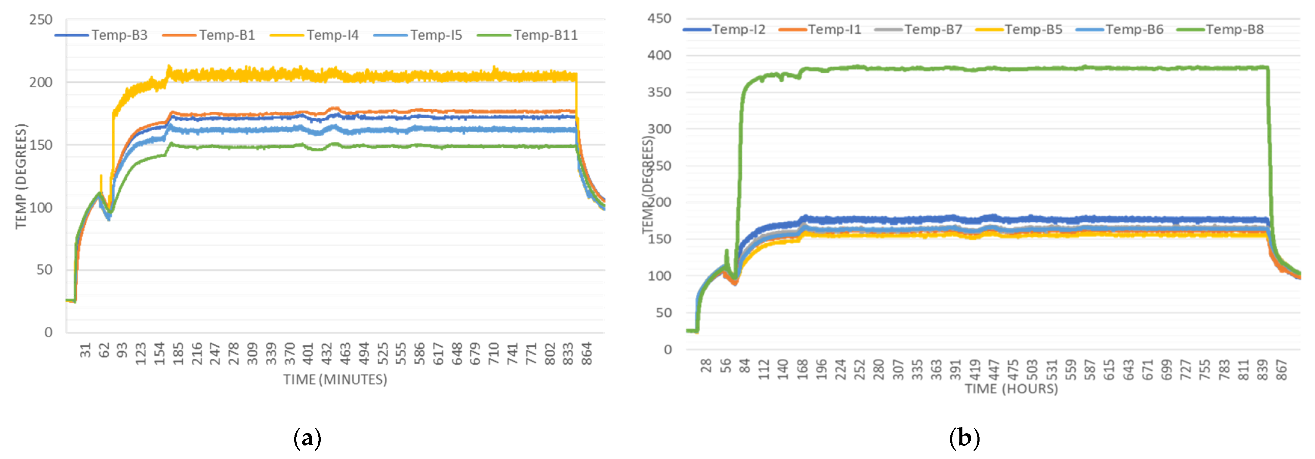
4.1. Temperature Variations during the Start-Up Process

The receiver tubes are very thin. Hence fins were spot-welded to serve as a support between the tubes and to avoid any deformation under the high operating temperature. However, there is a significant drawback associated with attaching the fins, i.e., the losses due to heat conductance between the pipes and the fins. Heat flux impinging onto the fins surface, as well as conductance from pipes, caused radiation losses from the fins which cannot be counted. Although the losses were not high as the results depicted. However, it is assumed that losses are the same for all the fins.
The thermocouples B2 and B10 were attached on the first turn on the side panels of the receiver. The water was in the subcooled state at the inlets, and hence the temperature noted by these thermocouples is a little lower. B10 was attached a little deeper than the B2, and partially due to lesser convective losses, B10 showed relatively higher temperature as compared to the B2. B3 and B11 were attached on the opposite sides of the receiver. Compared with B2, B10 had more depth, and the convective heat loss was less, so the temperature was higher than B2 at high input energy levels. B11 and B3 were located on the same place of side panels; however, due to the difference in heat flux, there exists a temperature difference.
The thermocouples I4 and I5 were both located in the high heat flux region of the external receiver. The location of I5 was right at the peak flux region of Lamp 5, and hence the temperature recorded by I5 is much higher as compared to I4. The temperature at locations B4 and I1 was first less than the saturated temperature but later exceeded as the incoming wind from the cooling fans of the simulator was. The temperature variation on the side panels in Figure 6a. while the variation in the central panel, as shown in Figure 6b. As can be inferred from the figures, a steady-state was achieved after a while and the variation has not been too high. A little variation in the plots is due to uneven heat flux obtained onto the surface of the receiver as well as due to differences in the installed places as discussed above.

4.2. Thermal Efficiency Calculation at Steady State

The calculations were performed when the system reached the steady-state, by adjusting the water flow rate, steam pressure and keeping feedwater flow and steam flowrate from the steam tank the same. A plot of the system achieving the steady-state over time is shown in Figure 7.
Calculations are based on the weight of steam produced. Energy transfer from the receiver surface to the water through the receiver tubes was evaluated to be around 8.34 kW, whereas the solar energy impinging onto the surface of the receiver was 9.5006 kW. So, the receiver’s efficiency under 0.5 MPa steady-state was 87.8%.

5. Numerical Simulations

To validate the results obtained from the experiment, numerical simulations were performed under similar conditions. An external receiver similar in shape and dimensions were designed in SolidWorks along with the same fan size. The wind velocity was measured with the help of an anemometer The same was provided as the boundary condition for the fans in the numerical simulations. The receiver front was made up of stainless steel and the support on the sides as well back was considered adiabatic as it served as insulation in the experiment to lessen the heat losses.
The domain width was also in line with the actual experimental platform while the length was increased for air to flow smoothly. The radiation losses were evaluated using the DO radiation model, whereas, natural convection was not considered as the experiment was carried out indoors without getting influenced by the outside atmosphere. The average temperature as measured of the surface of the receiver through the thermocouples at the front of the receiver was applied as the temperature boundary.
The mesh around the vicinity of the receiver was much denser near the receiver’s surface than that at the ends of the fluid domain. The boundary layer was primarily taken care of with the wall’s functions method. The y+ values lie within <10, with a few mesh layers very close to the airflow field. As explained earlier, the mesh was fine near the receiver and became coarser in the vicinity.
Hence, enhanced wall functions were used in the specified range to take care of the near-wall treatment. A mesh-independence study was also performed based on the residual error of convective heat losses. It was observed that a total of 1.1 × 10⁵ cells was adequate to carry.
For the numerical, the standard k-ε turbulent model was employed. The gravity was considered in the simulation. Since the atmospheric air pressure in experimental surroundings varies negligibly in the whole air domain and remains nearly 1 atm. Therefore, it was kept the same. The convergence criteria and operating conditions along with other details of the numerical simulations were kept in line with previous similar numerical studies [7,48], and these are summarized and enlisted in Table 4 [35,45,46].
For the airflow field simulations, the surrounding around the simulator was also included, to avoid any influence of the boundaries on the numerical results. Adequate size of the whole domain along with conditions was incorporated at the inlet boundary, with the flow direction of the wind targeted towards the receiver’s surface. For inlet flow, the turbulence intensity of 5% and an eddy viscosity ratio of 10 were assumed at the boundary and are computed locally during the simulations in the whole domain.
The velocity profiles show a complex airflow field around the receiver. The seven xenon lamps equipped with the fans aim to face the receiver front face resulting in high turbulence as these cross each other. The velocity is highest as it leaves the receiver at the top and bottom of the receiver away from the center as the high speeds disturb the zone stratification and lead to higher losses. Velocity vector profiles from different angles are shown in Figure 8. A close-up view of the velocity vectors is shown striking the receiver’s surface.
The air from the fans is directed towards the center in line with the direction of the lamps. There exists a small low velocity/stagnant zone at the center. The region has been marked in Figure 9a, it also blocks the incoming air and results in low heat transfer in the same area as described earlier. The velocity increases as away from the center and is significantly high near the edges of the receiver, where the air separation occurs. Corollary heat transfer also increases with the diminishing of the stagnant region.
The heat losses were numerically evaluated from results obtained through simulations and results were compared to those obtained through the experiment.

6. Results Comparison and Validation

The thermal efficiency of a receiver is defined as the ratio of energy absorbed by the Heat transfer fluid flowing in the receiver pipes’ to the total incident energy given by the lamps, this can be mathematically expressed as
η = Q a Q i n c
where Qa represents absorbed heat and Qinc indicates the total incident energy.
Qa can be evaluated using the
Q a = Q c + Q a d d
where, Qa = Total power absorbed by the receiver (kW)
Qc = Heat absorbed by the condenser (kW)
Qadd = Heat absorbed due to non-consistent water level (kW). The water supplied into the water tank is more than the amount of steam generated, deviation in heat absorbed due to additional water is compensated by the addition of Qadd into Qc.
The heat absorbed by the condenser was evaluated using
Q c = q c , m c p ( T c , i n T c , o u t )
where, qc,m represent the cooling water flowrate measured in kg/h.
Tc,in and Tc,out represent the temperature at the inlet and the outlet of the cooling water.
The difference between heat absorbed by the water and the steam generated can be evaluated using the equation
Q a d d = ( m ˙ f e e d w a t e r m ˙ s t e a m ) ( h m i x h f e e d w a t e r )
whereas m ˙ = flowrate (feed-water and steam)
hmix = saturated water enthalpy in the liquid state
hfeedwater = enthalpy of feed-water.
The reflectivity of steel was taken into account, and the efficiency of the receiver was measured around to be 83.92%. The results from the simulation are measured by evaluating the convective and radiation heat losses through the numerical simulations carried out via FLUENT, and the thermal efficiency of the receiver is found to be 87.8%. The difference in the receiver can be primarily due to
  • Complex heat transfer phenomenon in the experimental setup, which cannot be exactly replicated for the numerical simulations.
  • Insulation of pipes and receiver support may not be as practically accurate and reasonable as in the numerical simulations.
  • Possible presence of minor hairline cracks or gaps at the joints that may have resulted in leaking generated steam.
  • Other obvious human and experimental errors that may have occurred such as equipment accuracy etc.

7. Conclusions

The thermal efficiency of an external billboard receiver was numerically evaluated, and the ensuing results were validated through a series of experiments. Numerical simulations were conditions similar to those in the experimental setup that was synchronized. The cooling lamps located at the back of the lamps in the experimental setup were simulated as the wind-producing source. The wind velocity was measured in the experimental setup and the same was input as the boundary condition during the simulations. The average temperature, as measured onto the surface of the surface during the steady using the 16 thermocouples attached to the key locations of the receiver, was input at the surface of the external billboard receiver. During the experiment, the cold start-up and the performance of the external receiver at a steady-state were investigated under a pressure of 0.5 MPa. The fans attached at the back of the xenon lamps were responsible for the forced convective losses. The heat absorbed by the receiver and transferred to the water converts it to steam. The steam was then weighed to evaluate the thermal efficiency of the receiver. The efficiency of the receiver at a steady-state at 0.5 MPa was evaluated to be around 83.92%. The losses were evaluated by numerical simulations and compared between the results was found to be <5%. The wind direction was studied in a single direction due to cooling lamps being installed at the back of the lamp. The authors recommend extending the research by exploring the effect of wind in various directions. Similarly, the research should be extended to other receiver shapes with different arrangements of the heliostats/lamps to have a more realistic condition of the heat flux as in the real scenario.

Author Contributions

Conceptualization, J.F.; methodology, J.F., J.W.; software, M.A.Q., N.A.; validation, M.A.Q., J.F. and Y.J.; formal analysis, J.F., M.A.Q. and M.K.; investigation, J.W. and N.T.; resources, J.W., Z.W.; data curation, J.F. and M.A.Q.; writing—original draft preparation, M.A.Q.; writing—review and editing, J.F. and N.T.; visualization, M.A.Q. supervision, J.W.; project administration J.W.; funding acquisition, J.F. All authors have read and agreed to the published version of the manuscript.

Funding

The present work is supported by the Key Research Project of Shaanxi Province (NO.2017ZDXM-GY-017), Yulin Science and Technology Project (NO.2017KJJH-03), Natural Science Foundation of Shaanxi Province of China (NO: 2022JQ-327), and the Fundamental Research Funds for the Central Universities (Creative Team Plan No. cxtd2017004) in Xi’an Jiaotong University.

Institutional Review Board Statement

Not applicable.

Informed Consent Statement

Not applicable.

Data Availability Statement

Not applicable.

Acknowledgments

The authors particularly thank the coauthor Professor Jinjia Wei for providing the experimental platform and guidance. The coauthor Zhenjie Wan’s contribution while setting up the experimental platform is also of particular mention.

Conflicts of Interest

The authors declare no conflict of interest.

References

  1. Clausing, A.M. An analysis of convective losses from cavity solar central receivers. Sol. Energy 1981, 27, 295–300. [Google Scholar] [CrossRef]
  2. Clausing, A.M. Convective Losses from Cavity Solar Receivers—Comparisons between Analytical Predictions and Experimental Results. J. Sol. Energy Eng. 1983, 105, 29. [Google Scholar] [CrossRef]
  3. Koenig, A.A.; Marvin, M. Convection Heat Loss Sensitivity in Open Cavity Solar Receivers; DOE Contract No. EG77-C-04-3985; Department of Energy: Washington, DC, USA, 1981. [Google Scholar]
  4. Le Quere, P.; Penot, F.; Mirenayat, M. Experimental study of heat loss through natural convection from an isothermal cubic open cavity. In Proceedings of the DOE/SERI/SNLL Workshop on Convective Losses from Solar Receivers; Sandia National Labortories Report; Sandia National Labortories: Albuquerque, NM, USA, 1981; pp. 165–174. [Google Scholar]
  5. Harris, J.A.; Lenz, T.G. Thermal Performance of Solar Concentrator/Cavity Receiver Systems. Sol. Energy 1985, 34, 135–142. [Google Scholar] [CrossRef]
  6. Kraabel, J. An Experimental Investigation of the Natural Convection From A Side-Facing Cubical Cavity. In Proceedings of the ASME-JSME Thermal Engineering Conference Proceedings, Honolulu, Hawaii, 20–24 March 1983; American Society of Mechanical Engineers: New York, NY, USA; pp. 299–306. [Google Scholar]
  7. Siebers, D.L.; Kraabel, J.S. Estimating Convective Energy Losses from Solar Central Receivers; Sandia National Labs.: Livermore, CA, USA, 1984. [Google Scholar]
  8. McMordie, R.K. Convection Heat Loss from a Cavity Receiver. J. Sol. Energy Eng. 1984, 106, 98. [Google Scholar] [CrossRef]
  9. Stine, W.B. Cavity receiver convection heat loss. In Proceedings of the International Solar Energy Society. Solar World Congress, Kobe, Japan, 4–8 September 1989; Volume 1318. [Google Scholar]
  10. Balaji, C.; Venkateshan, S.P. Interaction of surface radiation with free- convection in a square cavity. Int. J. Heat Fluid Flow 1993, 14, 260–267. [Google Scholar] [CrossRef]
  11. Behnia, M.; Reizes, J.A.; Davis, G.D.V. Combined radiation and natural convection in a rectangular cavity with a transparent wall and containing a non-participating fluid. Int. J. Numer. Methods Fluids 1990, 10, 305–325. [Google Scholar] [CrossRef]
  12. Leibfried, U.; Ortjohann, J. Convective heat loss from upward and downward-facing cavity solar receivers: Measurements and calculations. J. Sol. Energy Eng. 1995, 117, 75–84. [Google Scholar] [CrossRef]
  13. Pavlovic, M.; Penot, F. Experiments in the mixed convection regime in an isothermal open cubic cavity. Exp. Therm. Fluid Sci. 1991, 4, 648–655. [Google Scholar] [CrossRef]
  14. Ma, R.Y. Wind Effects on Convective Heat Loss from a Cavity Receiver for a Parabolic Concentrating Solar Collector; Sandia National Labs.: Albuquerque, NM, USA; California State Polytechnic Univ.: Pomona, CA, USA, 1993; pp. 1–160. [Google Scholar]
  15. Radosevich, L.G. SAND87-8022; Final Report on the Power Production Phase of the 10 MWe Solar Thermal Central Receiver Pilot Plant. Sandia National Laboratories: Albuquerque, NM, USA, 1988.
  16. Bradshaw, R.W.; Dawson, D.B.; de La Rosa, W.; Gilbert, R.; Goods, S.H.; Hale, M.J.; Jacobs, P.; Jones, S.A.; Kolb, G.J.; Pacheco, J.E.; et al. NM 87185-0703; Final Test and Evaluation Results from the Solar Two Project; Energy Storage. US Department of Energy, Sandia National Laboratories: Albuquerque, NM, USA, 2002.
  17. Jin, Y.; Fang, J.; Wei, J.; Qaisrani, M.A.; Wang, X. Homogenization of solar flux distribution in a carbon aerosol entrapped cavity receiver. Energy 2019, 182, 21–36. [Google Scholar] [CrossRef]
  18. Hahm, T.; HSchmidt–Traub Le Mann, B. A Cone Concentrator for High-Temperature Solar Cavity-Receivers. Sol. Energy 1999, 65, 33–41. [Google Scholar] [CrossRef]
  19. Ramesh, N.; Venkateshan, S.P. Effect of Surface Radiation on Natural Convection in a Square Enclosure. J. Thermophys. Heat Transf. 2012, 13, 299–301. [Google Scholar] [CrossRef]
  20. Kribus, A. Future Directions in Solar Thermal Electricity Generation. Solar Thermal Electricity Generation; Colección Documentos CIEMAT: Madrid, Spain, 1999; pp. 251–285. [Google Scholar]
  21. Kaushika, N.D.; Reddy, K.S. Performance of a low cost solar paraboloidal dish steam generating system. Energy Convers. Manag. 2000, 41, 713–726. [Google Scholar] [CrossRef]
  22. Pacheco, J.E.; Reilly, H.E.; Kolb, G.J.; Tyner, C.E. Summary of the Solar Two Test and Evaluation ProgramSandia National Lab.(SNL-NM), Albuquerque, NM (United States); Sandia National Lab.(SNL-CA): Livermore, CA, USA, 2000. [Google Scholar]
  23. Paitoonsurikarn, S.; Taumoefolau, T.; Lovegrove, K. Investigation of Natural Convection Heat Loss from a Solar Concentrator Open Cavity Receiver at Varying Angle of Inclination. In Proceedings of the ASME 2003 International Solar Energy Conference, Kohala Coast, HI, USA, 15–18 March 2003; pp. 611–617. [Google Scholar]
  24. Paitoonsurikarn, S.; Taumoefolau, T.; Lovegrove, K. Estimation of convection loss from paraboloidal dish cavity receivers. In Proceedings of the 42nd Conference of the Australia and New Zealand Solar Energy Society (ANZSES), Perth, Australia, 30 November–3 December 2004; pp. 1–7. [Google Scholar]
  25. Paitoonsurikarn, S.; Lovegrove, K. Effect of paraboloidal dish structure on the wind near a cavity receiver. In Proceedings of the 44th Annual Conference of the Australian and New Zealand Solar Energy Society, Canberra, Australia, 13–15 September 2006. [Google Scholar]
  26. Paitoonsurikarn, S.; Lovegrove, K.; Hughes, G.; Pye, J. Numerical Investigation of Natural Convection Loss From Cavity Receivers in Solar Dish Applications. J. Sol. Energy Eng. 2011, 133, 021004. [Google Scholar] [CrossRef]
  27. Schmitz, M.; Schwarzbözl, P.; Buck, R.; Pitz-Paal, R. Assessment of the potential improvement due to multiple apertures in central receiver systems with secondary concentrators. Sol. Energy 2006, 80, 111–120. [Google Scholar] [CrossRef] [Green Version]
  28. Schwarzbözl, P.; Pitz-Paal, R.; Schmitz, M. Visual HFLCAL-A software tool for layout and optimisation of heliostat fields. In Proceedings of the SolarPACES 2009, Berlin, Germany, 15–18 September 2009. [Google Scholar]
  29. Muftuoglu, A.; Bilgen, E. Conjugate heat transfer in open Cavities with a discrete heater at its optimized position. Int. J. Heat Mass Transf. 2008, 51, 779–788. [Google Scholar] [CrossRef]
  30. Prakash, M.; Kedare, S.B.; Nayak, J.K. Investigations on heat losses from a solar cavity receiver. Solar Energy 2009, 83, 157–170. [Google Scholar] [CrossRef]
  31. Fang, J.B.; Wei, J.J.; Dong, X.W.; Wang, Y.S. Thermal performance simulation of a solar cavity receiver under windy conditions. Sol. Energy 2011, 85, 126–138. [Google Scholar] [CrossRef]
  32. Tu, N.; Wei, J.; Fang, J. Experimental and numerical study on the thermal performance of a water/steam cavity receiver. Energies 2013, 6, 1198–1216. [Google Scholar] [CrossRef] [Green Version]
  33. Tu, N.; Wei, J.; Fang, J. Numerical study on thermal performance of a solar cavity receiver with different depths. Appl. Therm. Eng. 2014, 72, 20–28. [Google Scholar] [CrossRef]
  34. Fang, J.B.; Tu, N.; Wei, J.J. Numerical investigation of start-up performance of a solar cavity receiver. Renew. Energy 2013, 53, 35–42. [Google Scholar] [CrossRef]
  35. Fang, J.; Tu, N.; Wei, J.; Fang, T.; Du, X. Numerical investigation of the tube layout effects on the heat losses of solar cavity receiver. J. Therm. Sci. Eng. 2017, 10, 132. [Google Scholar] [CrossRef]
  36. Flesch, R.; Stadler, H.; Uhlig, R.; Pitz-Paal, R. Numerical analysis of the influence of inclination angle and wind on the heat losses of cavity receivers for solar thermal power towers. Sol. Energy 2014, 110, 427–437. [Google Scholar] [CrossRef] [Green Version]
  37. Flesch, R.; Stadler, H.; Uhlig, R.; Hoffschmidt, B. On the influence of wind on cavity receivers for solar power towers: An experimental analysis. Appl. Therm. Eng. 2015, 87, 724–735. [Google Scholar] [CrossRef]
  38. Kim Jongkyu Kim Jin-soo Stein, W. Simplified heat loss model for central tower solar receiver. Sol. Energy 2015, 116, 314–322. [Google Scholar]
  39. Stoddard, M.C. Convective Loss Measurements at the 10 MW.SOLAR Thermal Central Receiver Pilot Plant; Sandi a National Labs.: Livermore, CA, USA, 1986. [Google Scholar]
  40. Qaisrani, M.A.; Ahmed, N.; Wang, Q. Working, Modeling and Applications of Molten Salt TES Systems. In Synergy Development in Renewables Assisted Multi-Carrier Systems; Springer: Cham, Switzerland, 2022; pp. 279–309. [Google Scholar]
  41. Qaisrani, M.A.; Wei, J.; Khan, L.A. Potential and transition of concentrated solar power: A case study of China. Sustain. Energy Technol. Assess. 2021, 44, 101052. [Google Scholar] [CrossRef]
  42. Rodríguez-Sánchez, M.R.; Soria-Verdugo, A.; Almendros-Ibáñez, J.A.; Acosta-Iborra, A.; Santana, D. Thermal design guidelines of solar power towers. Appl. Therm. Eng. 2014, 63, 428–438. [Google Scholar] [CrossRef]
  43. Rodriguez-Sanchez, M.R.; Sanchez-Gonzalez, A.; Santana, D. Revised receiver efficiency of molten-salt power towers. Renew. Sustain. Energy Rev. 2015, 52, 1331–1339. [Google Scholar] [CrossRef]
  44. Rodriguez-Sanchez, M.D.L.R.; Sanchez-Gonzalez, A.; Marugan-Cruz, C.; Santana, D. Flow patterns of external solar receivers. Sol. Energy 2015, 122, 940–953. [Google Scholar] [CrossRef]
  45. Qaisrani, M.A.; Wei, J.; Fang, J.; Jin, Y.; Wan, Z.; Khalid, M. Heat losses and thermal stresses of an external cylindrical water/steam solar tower receiver. Appl. Therm. Eng. 2019, 163, 114241. [Google Scholar] [CrossRef]
  46. Qaisrani, M.A.; Fang, J.; Jin, Y.; Wan, Z.; Tu, N.; Khalid, M.; Rahman, M.U.; Wei, J. Thermal losses evaluation of an external rectangular receiver in a windy environment. Sol. Energy 2019, 184, 281–291. [Google Scholar] [CrossRef]
  47. Du, M.; Zhou, R.; Zhao, J.; Ling, X.; Liu, C. Thermal characteristics of grid flat-plate heat receiver in a solar power-tower system. Appl. Therm. Eng. 2021, 190, 116797. [Google Scholar] [CrossRef]
  48. Jin, Y.; Fang, J.; Wei, J.; Qaisrani, M.A.; Wang, X. Thermal performance evaluation of a cavity receiver based on particle’s radiation properties during the day time. Renew. Energy 2019, 143, 622–636. [Google Scholar] [CrossRef]
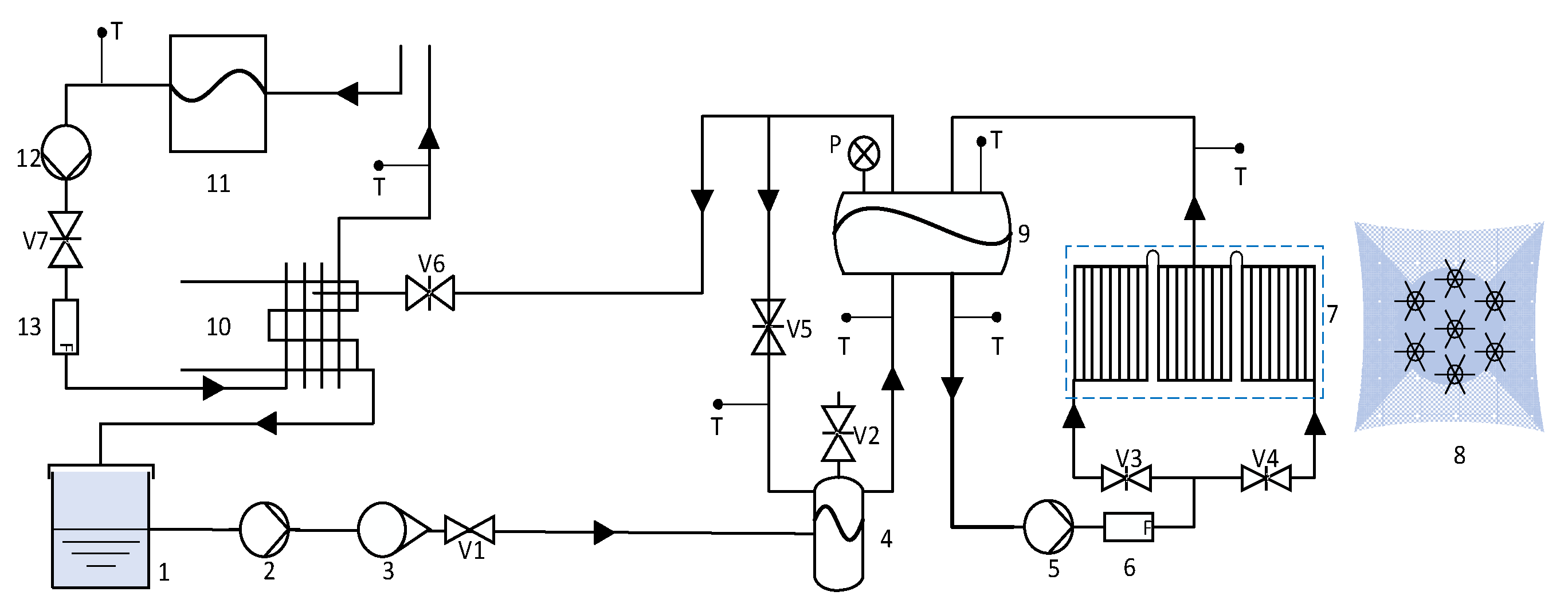
Figure 1. System sketch of the experimental platform.
Energies 15 02188 g001
Figure 2. Detailed schematic of the Receiver panel.
Energies 15 02188 g002
Figure 3. (a)Thermocouples distribution (b) The Solar simulator.
Energies 15 02188 g003
Figure 4. Heat flux measurement system.
Energies 15 02188 g004
Figure 5. Heat flux obtained on a lambert target produced by lamp 5.
Energies 15 02188 g005
Figure 6. Temperature distribution at receiver’s surface (a) Left and Right panels (b) Central panel.
Energies 15 02188 g006
Figure 7. Pressure against time plot showing steady−state.
Energies 15 02188 g007
Figure 8. Velocity vectors at the receiver surface from two different cross−sectional views. (a) Latitudinal view (b) Longitudinal view.
Energies 15 02188 g008
Figure 9. Velocity contours across the cross-section of the airflow domain. (a) Velocity contours across the airflow field with the stagnant zone marked (b) Cross−section of velocity contours across the domain.
Energies 15 02188 g009
Table 1. List of instruments.
No.ItemFunction
1Feed-water tankContains the feed water later sent to the receiver
2Feed-water pumpResponsible for pumping water out of the feed water tank
3FlowmeterGlass-tube rotameter to measure the mass flow rate at the outlet of the feed-water pump
4DeaeratorTo dearate the water, i.e., removes oxygen, gas bubbles and other dissolved gases from the water.
5Circulating Pump pumps water through the receiver tubes
6FlowmeterInstalled adjacent to the water circulating pump measures the reading at the outlet of the circulating pump.
7External ReceiverThe object of the study; responsible for transmitting energy from solar simulator to the HTF.
8Solar SimulatorToprovide the required thermal energy to the external receiver.
9Steam Tankand steam are separated in the steam tank
10CondenserSteam from the steam tank is cooled down in the steam condenser. The steam temperature decreases to the room temperature in the condenser
11Cooling towerIt is responsible for water intake needed for the experiment operation
12Cooling water pumpIt pumps water out of the cooling water tank into the feed water tank
13Cooling flow meterMeasures the water flow rate coming from the cooling water tank and flowing into the feed water tank
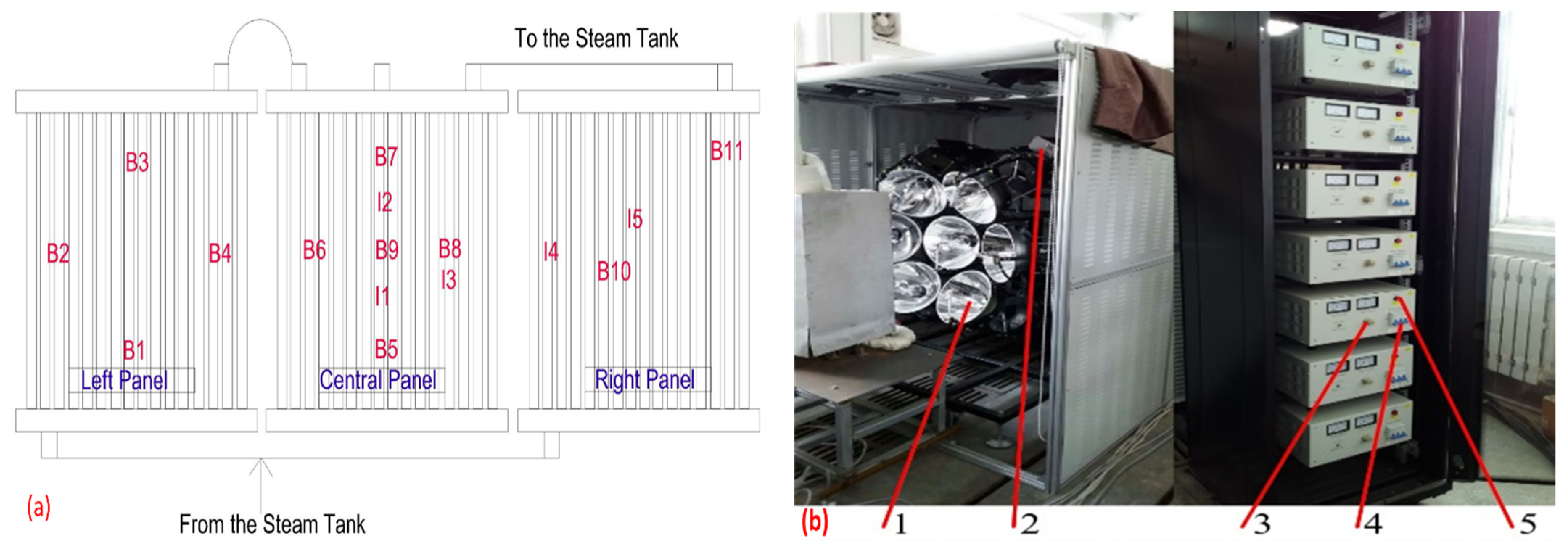
Table 2. Components of the solar simulator.
No.ItemFunction
1Xenon LampsThe main components of the solar simulator; are responsible for the producing desired heat flux at the surface of the external receiver tubes. As can be inferred from the picture, there is a total of seven xenon lamps
2TriggerThe cooling system consisting of fans to avoid overheating is also located in this portion
3Electric supply buttonThe Electric supply switch controls the amount of power for each lamp. The power can be controlled as required.
4Power switchThe main power switch for the controller for each panel. Each lamp has its panel showing values for current and voltage via the installed digital ammeter and voltmeter
5Xenon Lamp On/Off switchA simple on/off switch for each of the lamps
Table 3. Components of measurement system.
No.ItemFunction
1Data loggerFor data acquisition
2Target ControllerThe moving lambert target is moved and controlled via this target-controlled to achieve the flux at the desired location for measurement
3Cooling systemTo avoid the excessive heating of the equipment that may result in any sort of burning/damage to the equipment
4CCD CameraThe image for the heat flux obtained onto the target is captured to the camera installed at the upper part of the specific xenon lamp. The capture has a limited view and captures within a specific angle.
5Heat flux sensorThe sensor is attached at the back of the target to capture the heat flux distribution onto the target
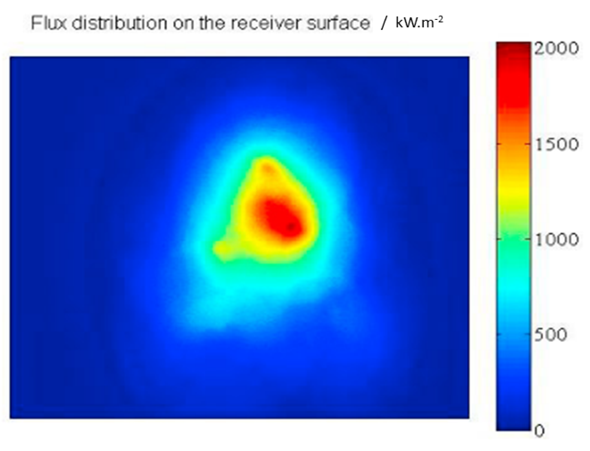
6The lambert targetThe heat flux distribution is obtained to this lambert target. The image captured via a camera, of the flux distribution at the surface of the lambert target, is shown later in Figure 5.
Table 4. Conditions and parameters for numerical simulations.
Parameters and ConditionsConfiguration/Settings Implied
SolverPressure-based solver in steady-state flow with respect to time
GradientLeast Square Cell-based methodology
AlgorithmThe Semi-implicit Method for the Pressure Linked Equation (SIMPLE)
Spatial Discretization settingsSecond order-upwind scheme for momentum as well as the energy equations, whereas for the turbulent dissipation rate and turbulent kinetic equation the first-order scheme was selected
Convergence CriteriaThe first-order scheme was chosen for velocity, κ and ε, and 10−6 for Energy
Publisher’s Note: MDPI stays neutral with regard to jurisdictional claims in published maps and institutional affiliations.

