Abstract
A printed circuit heat exchanger (PCHE) is an efficient and compact heat exchanger that can work under high temperature and high pressure. For Z-shaped channel PCHEs, the corner structure could enhance heat transfer at the expense of increasing the flow resistance. In order to optimize the structural design and control the pressure loss caused by the corner, a three-dimensional numerical simulation using ICEM and Fluent is conducted to study the flow and heat transfer characteristics of carbon dioxide in a PCHE by inserting straight sections (offset distance 0.5–4 mm) or arc segments (radius of curvature 0.5–4 mm) at the zigzag corners of conventional Z-shaped channels. The overall performance of the PCHEs with different structures was compared based on the comprehensive evaluation factor. The results show that the pressure loss of the PCHE can be significantly reduced by inserting straight sections and arc segments at the zigzag corners, with the mass flow rate varying from 100 to 400 kg/(m2 s). The greater the offset distance of the straight sections or curvature radius of the arc segments are, the more significant the effect is, but the heat transfer performance will be weakened at the same time. The comprehensive performance of the PCHE was the best when the curvature radius of the arc segment inserted at the zigzag corner was 4 mm.
1. Introduction
Heat exchangers are widely used in nuclear power generation, solar thermal power generation, marine LNG fuel supply, and many other systems. These heat exchangers operate under severe conditions, and their performance has a significant impact on the energy conversion efficiency, safety, and economy of the system [1]. The printed circuit heat exchanger (PCHE) is an efficient compact heat exchanger. Its manufacture includes two key processes: photochemical etching technology and diffusion welding technology. Usually, the plate thickness of the PCHE is less than 5 mm, and the channel section is mostly a semicircle with a diameter of 0.5–5 mm [2], which makes the heat transfer area per unit volume of the PCHE very large and the structure compact. Due to the small hydraulic diameter of the channel, the PCHE can withstand high pressure.
The channel forms of the PCHE mainly include straight channels, Z-shaped channels, S-shaped fin channels, and airfoil fin channels. In order to understand the effect of structural changes on the flow and heat-transfer characteristics and to design a heat exchanger with better performance, scholars have carried out a great deal of research. Jeon et al. [3] proposed a new structure of semicircular straight channels arranged in a cross and studied the influence of channel size, channel spacing, and channel cross-sectional shape on thermal performance. Kim et al. [4] studied the effects of design parameters such as the bend angle, pitch, and hydraulic diameter on the thermal–hydraulic performance of the semicircular section Z-shaped channel PCHE, which is used as an intermediate heat exchanger in high-temperature gas-cooled reactors. According to the correlation between the Fanning friction factor and Nusselt number, the optimal design of an intermediate heat exchanger is determined via optimization analysis of the capital cost and operating cost. Gao et al. [5] numerically analyzed the effects of pipe diameter (1–6 mm) and bend angle (5–60°) on the heat transfer and pressure drop of a Z-shaped PCHE. Lin et al. [6] simulated the heat transfer and resistance performance of Z-shaped and waveform channel PCHEs at different bend angles (10°, 20°, 30°) under Reynolds numbers of 5000–30,000. Lee et al. [7] studied the effect of the half-ellipse aspect ratio (0.5–1.5) on the efficiency and pressure drop of a Z-shaped channel PCHE where supercritical carbon dioxide was used as the working fluid; they found that with increasing half-ellipse aspect ratio of the cold channel, both the PCHE efficiency and the dimensionless pressure drop increased, and the heat flux was the largest when the half-ellipse aspect ratio was 1. Bartel et al. [8] designed a compact heat exchanger in an advanced nuclear reactor system and compared the performance of Z-shaped channels with different bend angles and straight channels with offset rectangular fins. Cheng et al. [9] studied the effects of different mass flows and inlet temperatures in the supercritical carbon dioxide channel and water channel on the heat transfer, pressure drop, and efficiency of a PCHE when a Z-shaped channel PCHE was used as a precooler. Ngo et al. [10] applied the S-fin PCHE to a water heater, and the compactness of the PCHE was 3.3 times greater than that of the traditional water heater under the same heat transfer. Pidaparti et al. [11] studied the different thermal–hydraulic performances of PCHEs with discontinuous offset rectangular fins and NACA0020 airfoil fins through experiments, and they proposed new correlations between the Nusselt number and resistance for these two shapes of PCHEs. Tang et al. [12] numerically simulated and studied the airfoil PCHE with a vortex generator with liquefied natural gas as the working fluid, and they came to the conclusion that the heat transfer performance is the best when the minimum transverse pitch of the vortex generator is twice the maximum thickness of the airfoil.
The Z-shaped channel has a simple manufacturing process, low cost, and good heat transfer performance, but there is also high pressure loss; the zigzag corners in particular have a greater impact on the pressure drop and heat transfer performance. In this study, straight sections or arc segments were inserted at the zigzag corners to optimize the structural design and control the pressure loss caused. To study the effect on the flow and heat-transfer characteristics of carbon dioxide in the Z-shaped channel PCHEs with different zigzag corner structures, the numerical simulation method was used. The performance of the PCHEs with different structures was compared based on the comprehensive evaluation factor.
2. Numerical Methodology
2.1. Physical Model
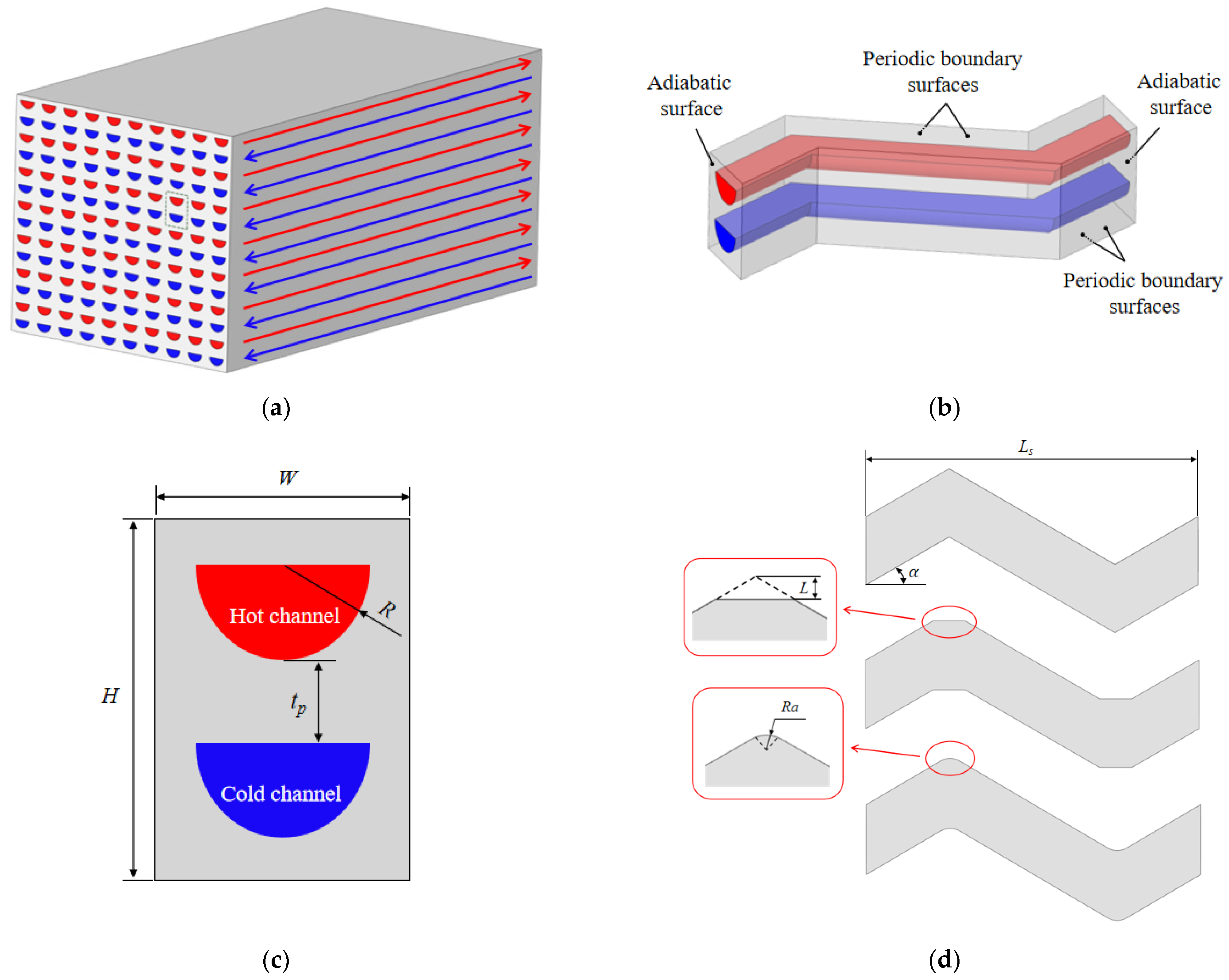
Figure 1 shows the heat exchanger core, the arrangement of the flow channels and the boundary conditions of the solid walls. The microchannel structure is etched on the surface of metal plate by photochemical etching technology, and then the cold and hot plates are stacked together alternately. The atoms on both sides of the plate contact surface are diffused and connected through diffusion welding to form a complete heat exchanger core. Establishment and numerical simulation of the complete heat exchanger model would take a lot of time, so it must be simplified. Based on its arrangement structure and periodic variation, the heat exchange unit structure of a double-layer microchannel, including one cold channel, one hot channel, and their wall, was selected for research in this article. The working fluids in the upper channel and the lower channel are hot carbon dioxide fluid and cold carbon dioxide fluid, respectively. The working fluid flow is countercurrent. The red arrows on the wall in Figure 1a mean the flow directions of the hot working fluid and the blue arrows mean the flow directions of the cold working fluid. The solid material is 316 L stainless steel, and its thermal conductivity coefficient is 16.2 W/(m2 K). Figure 1d shows the single pitch of the conventional Z-shaped channel and two types of Z-shaped channels with straight sections or arc segments inserted at the zigzag corners. The width, W, and height, H, of the solid domain are 3.2 mm and 4.4 mm, respectively. The radius, R, of cold channel and hot channel is 1 mm. The spacing of the hot and cold channels, tp, is 1.2 mm. The offset distance, L, of the straight sections inserted at the corner is 0.5–4 mm, and the curvature radius, Ra, of the inserted arc segments is 0.5–4 mm. The bend angles, α, of the Z-shaped channels are all 30°. The single pitch length, Ls, of the channel researched in this article is 18 mm, with a total of 15 pitches.

Figure 1.
Schematic diagram of the structure of PCHE: (a) heat exchanger core; (b) Z-shaped channel single-pitch heat exchange unit structure; (c) the cross section of the heat exchange unit; (d) the single pitch of the conventional Z-shaped channel and two types of Z-shaped channels with straight sections or arc segments inserted at the zigzag corners.
2.2. Grid Independence Verification
ICEM was used to divide the solid and fluid domains of the PCHE into structured meshes. O-shaped mesh was adopted for the semicircular sections, and the fluid domain mesh was refined near the fluid–solid coupling surface. The first layer of grid was established with a height of 0.005 mm and a growth rate of 1.2, a total of ten layers.
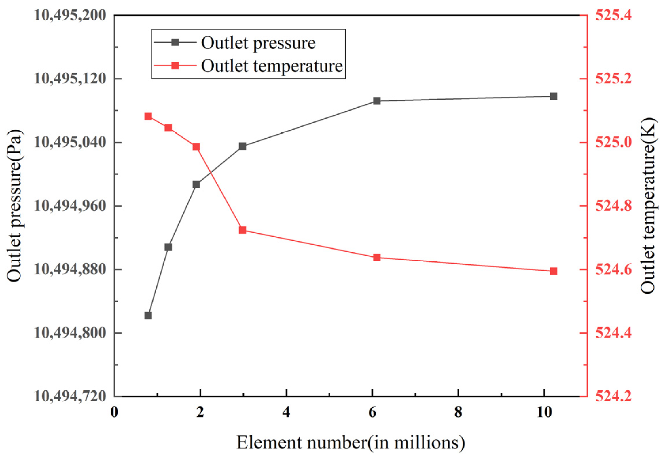
The results of numerical calculation produce errors with different numbers of grid cells. To improve the accuracy of numerical simulation and save computing resources, it is necessary to verify the grid independence. Numerical simulations of PCHEs with different mesh numbers were carried out under the same working conditions and physical model. As shown in Figure 2, six models with different grid totals ranging from 0.789 M to 10.22 M cells were simulated; when the total number of grid cells reached more than 6,107,229, the calculation results for the outlet pressure and outlet temperature were basically stable. Therefore, the model with a total number of 6,107,229 grid cells was selected for the numerical calculation.
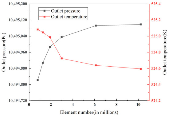
Figure 2.
PCHE grid independence verification.
2.3. Boundary Conditions and Solution Methods
Commercial software ANSYS Fluent 2020 was used to carry out numerical simulation of the conventional Z-shaped channel PCHE and the optimized models. The top, bottom, left, and right walls of the solid domain were set as periodic boundary conditions; the front and rear walls were set as adiabatic boundary conditions; and the interface between the solid domain and the fluid domain was connected by fluid–solid coupling. The inlet of the fluid domain was adopted as the mass flow inlet, and the outlet adopted was the pressure outlet. The inlet temperature and pressure of the hot fluid were set to 553.15 K and 3.2 MPa, respectively, and the inlet temperature and pressure of the cold fluid were set to 381.15 K and 10.5 MPa, respectively. The inlet mass flow rates of the cold and hot fluids were considered equal, and they were 100–400 kg/(m2 s), increasing by 50 kg/(m2 s). The physical properties of carbon dioxide were obtained from REFPROP software. Since the pressure drop accounts for a small proportion in the whole process, assuming that the pressure is constant, the polynomials of the physical properties changing with temperature were fitted by MATLAB, as shown in Table 1, and written into User-Defined Function (UDF) for Fluent to call. The polynomial goodness of fit of density, thermal conductivity and dynamic viscosity is higher than 0.99, and the goodness of fit of specific heat capacity is also higher than 0.97. In addition, the main calculation basis of the mass flow inlet is the mass flow rate and temperature, and the main calculation basis of the pressure outlet is the outlet pressure, but we only know the actual inlet temperature and inlet pressure. Thus, UDF needs to be called at the pressure outlet to iterate the outlet pressure to a suitable value where the inlet pressure calculated according to the outlet pressure reaches the value we already know; the suitable outlet pressure is then the pressure value we set in the pressure outlet.

Table 1.
Carbon dioxide physical properties polynomial fitting results.
The SIMPLE algorithm was used to set up the coupling of the velocity and pressure. The variable gradient was solved by the least-squares cell-based method. For the pressure equation, the standard discrete scheme was applied; for the momentum and energy equations, the second-order upwind scheme was applied; for the turbulence equation, the first-order upwind scheme was applied. The convergence accuracy of all variables was 10−6.
2.4. Model Validation
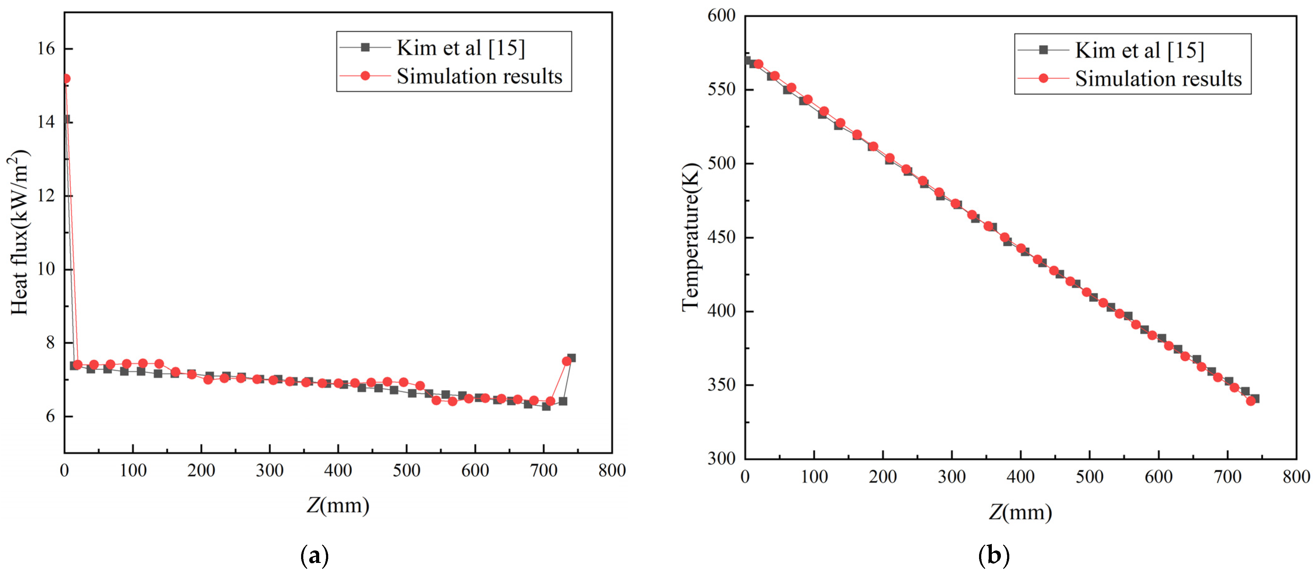
According to the research, the turbulence model can accurately reflect the heat transfer and flow characteristics of the PCHE [5,13,14]. In order to further illustrate the feasibility of the turbulence model, for this article, the same conditions and models as those used by Kim [15] were selected for the numerical simulation. The inlet temperatures of the cold and hot sides were 335.05 K and 576.45 K, respectively; the mass flows were both 1.683 × 10⁻⁵ kg/s; and the inlet pressures were both 1.9 MPa. As shown in Figure 3, the simulation results are basically consistent with the results of Kim et al., which verifies the reliability of the turbulence model selection and numerical calculation.
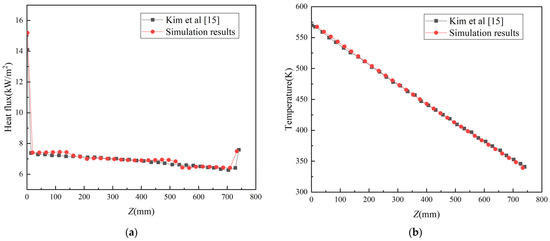
Figure 3.
Comparison of heat flux and fluid temperature simulation results with those from Kim et al.: (a) heat flux; (b) fluid temperature.
2.5. Data Processing
The Fanning friction factor is calculated according to Equation (1):
where ΔPf is the pressure drop of the channel, ρ is the average density of the fluid, Lf is the flow path length of the fluid, u is the average velocity of effective section in channel, and Dh is the hydraulic diameter, which can be determined according to Equation (2):
where V is the volume of the fluid channel, and A is the pipe wall surface area of fluid flows.
The convective heat transfer coefficient and Nusselt number are calculated by Equations (3) and (4), respectively:
where q is the average heat flux of the channel, Tw is the wall temperature, Tb is the average temperature of the fluid, and λ is the average thermal conductivity of the fluid.
Given the cold and hot fluid domains’ inlet and outlet temperatures, channel section, and mass flow rate, to achieve the same heat transfer when PCHEs have the same total flow area, Z-shaped channel PCHEs with different zigzag corner structures require different channel total lengths, and their fluid flow resistance differs. According to Equations (1), (3) and (4), the comprehensive evaluation factor ζ of the heat exchanger can be defined in Equation (5) to characterize the level of fluid resistance in PCHEs with different zigzag corner structures when transferring the same heat, so as to reflect the relative operation cost of the PCHE.
The volume and weight of a PCHE are characterized by the ratio Lz/Lzref to reflect the relative manufacturing cost of the PCHE:
where Lz is the total length of the PCHE, and the subscript ref represents the conventional Z-shaped channel PCHE.
3. Results and Discussion
3.1. Effect of Inserting Straight Sections at Zigzag Corners in Z-Shaped Channels
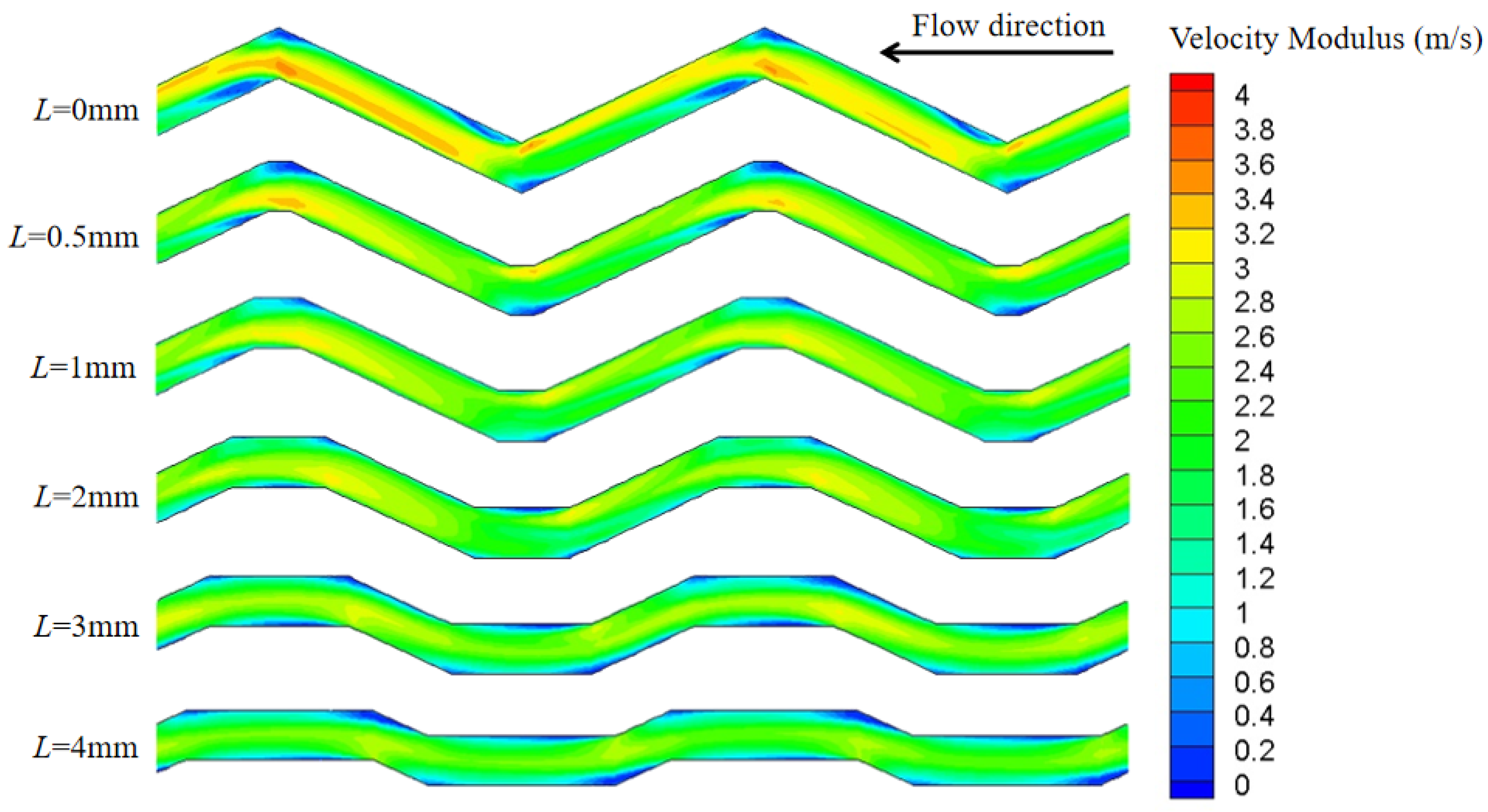
Figure 4 is the velocity modulus in the 7th–8th pitch of the cold channels with the insertion of straight sections with offset distance ranging from 0 mm to 4 mm when the inlet mass flow rate is 250 kg/(m2 s). When the offset distance of the inserted straight sections is 0 mm, it represents the conventional Z-shaped channel. It can be seen from Figure 4 that the overall velocity of the supercritical carbon dioxide (S-CO2) in the conventional Z-shaped channel is larger than that in the optimized channel, and the velocity changes drastically when passing through the corners. As the offset distance of the straight sections increases, the fluid velocity decreases. Moreover, due to the effect of wall viscosity force and differential pressure force, there is the stagnant area near the corner, and the main flow is pushed to the other side of the channel.
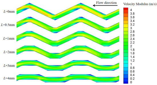
Figure 4.
Velocity modulus for different offset distances of inserted straight sections.
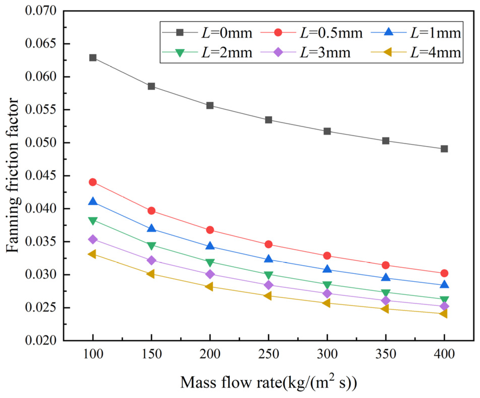
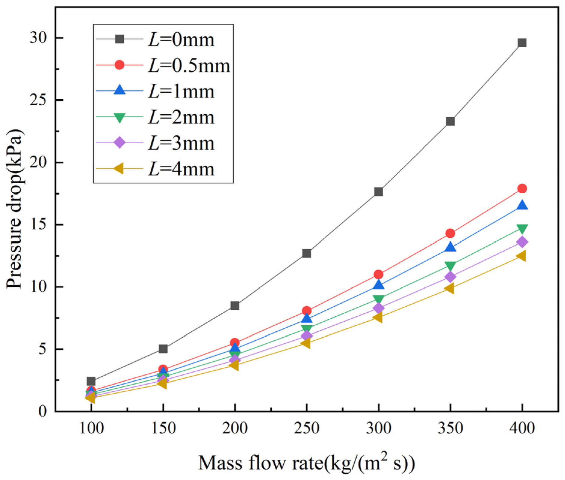
Figure 5 and Figure 6 show the variation in the PCHE friction factor and pressure drop with the mass flow rate when different straight sections are inserted. It can be seen from Figure 5 that under the same mass flow rate, the friction factor of the conventional Z-shaped channel is the largest, and the friction factor decreases with the increasing offset distance of the inserted straight sections. When the offset distance of the inserted straight section is 4 mm, the friction factor is the smallest. In addition, the friction factor decreases with increasing mass flow rate. The pressure drop is comprehensively affected by the friction factor, structural size of the heat exchanger, and flow rate. It can be seen from Figure 6 that the pressure drop of the conventional Z-shaped channel PCHE is much larger than that of the PCHEs with inserted straight sections, and the pressure drop decreases with increasing offset distance of the inserted straight sections. When the mass flow rate is 400 kg/(m2 s), the pressure drop values of the PCHEs with 0.5 mm, 1 mm, 2 mm, 3 mm, and 4 mm straight sections are 39.56%, 44.25%, 50.21%, 54.01%, and 57.77% lower than that of the conventional Z-shaped channel PCHE. Further, the pressure drop of the PCHEs increases with increasing mass flow rate, and the increasing trend becomes more significant. The pressure drop of the PCHE with 4 mm straight sections is about 54.47–57.77% lower than that of the conventional Z-shaped channel PCHE.
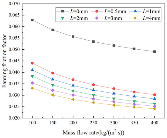
Figure 5.
Fanning friction factor values of PCHEs at different mass flow rates for different offset distances of inserted straight sections.
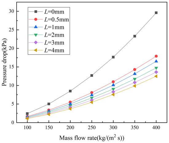
Figure 6.
Pressure drop values of PCHEs at different mass flow rates for different offset distances of inserted straight sections.
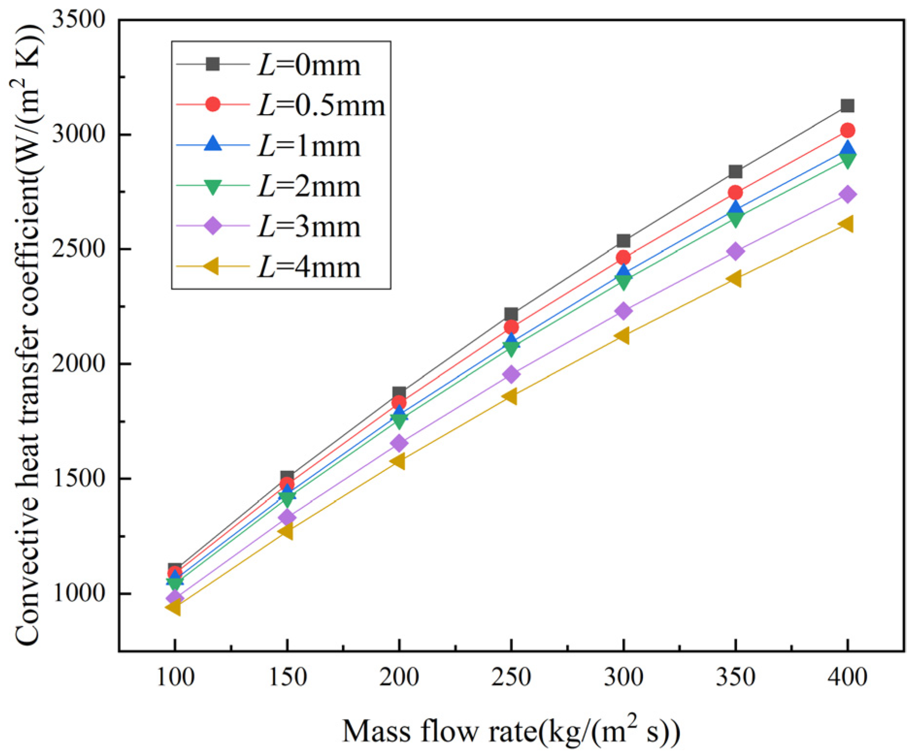
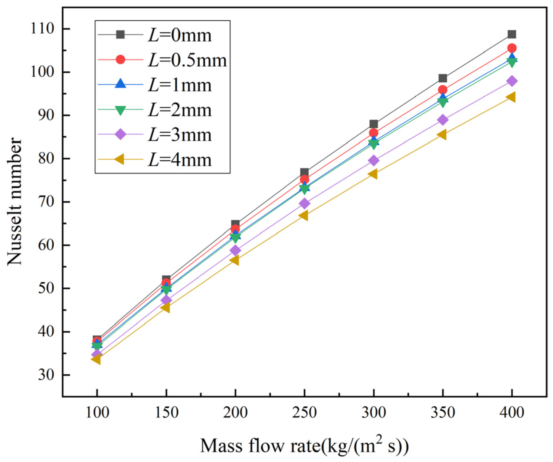
Figure 7 and Figure 8, respectively, show the variation in the convective heat transfer coefficient h and Nusselt number Nu with the mass flow rate for the PCHEs with different inserted straight sections. It can be seen from the figure that the variations in the convective heat transfer coefficient of the conventional Z-shaped channel and the channels with inserted straight sections have the same trend of increase with increasing mass flow rate. The heat transfer performance of the conventional Z-shaped channel PCHE is the best, while the heat transfer performance of the PCHE with 4 mm straight sections is poor. The convective heat transfer coefficient of the PCHE with 4 mm straight sections is about 14.76–16.48% lower than that of the conventional Z-shaped channel PCHE. The heat transfer performance of the PCHEs decreases with increasing offset distance of the inserted straight sections. When the mass flow rate is 400 kg/(m2 s), the convective heat transfer coefficient of the PCHE with 0.5 mm straight sections is 3.44% lower than that of the conventional Z-shaped channel PCHE.
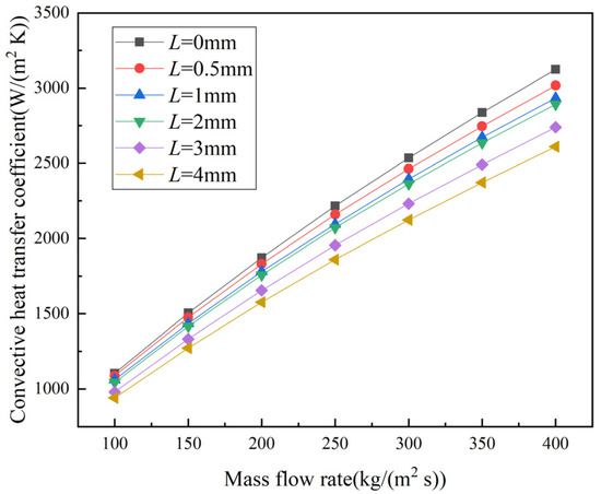
Figure 7.
Convective heat transfer coefficient values of PCHEs at different mass flow rates for different offset distances of inserted straight sections.
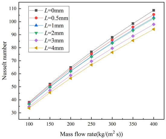
Figure 8.
Nusselt number values of PCHEs at different mass flow rates for different offset distances of inserted straight sections.
The above phenomena are mainly related to the following points. First of all, the flow direction of the S-CO2 changes abruptly at the corners of the conventional Z-shaped channel. The phenomenon of flow separation is obvious. There are stagnant areas near the wall to consume pressure. At the same time, the main flow is pushed to the other wall, the turbulence near the other wall is enhanced, and the irregular flow destroys the near-wall boundary layer and strengthens convective heat transfer. However, when the straight sections are inserted, the change in the flow directions of the fluid at the corners is not as sharp as that of the conventional zigzag corner, and the existence of the straight sections provides transition sections for the fluid flowing around the corner. Secondly, the S-CO2 in the conventional Z-shaped channel collides with the wall after flowing around the corner, the velocity distribution of the fluid is irregular, and the main flow friction is intensified, resulting in pressure loss. At the same time, the violent mixing between various parts of the fluid enhances the heat exchange. The insertion of the straight sections reduces the bend angle in a sense, reduces the probability of the S-CO2 hitting the wall, and eases the increase in pressure drop and heat transfer performance. In addition, with the increasing offset distance of the inserted straight sections, the flow paths of the fluid in the optimized channels are smaller than those of the conventional Z-shaped channel, the resistance along the way is reduced, and the effective heat transfer area is reduced, which is also the reason for the reduction in the pressure drop and heat transfer performance.
3.2. Effect of Inserting Arc Segments at Zigzag Corners in Z-Shaped Channels
Figure 9 is the velocity modulus in the 7th–8th pitch of the cold channels with the insertion of arc segments with curvature radius ranging from 0 mm to 4 mm when the inlet mass flow rate is 250 kg/(m2 s). The channel where the inserted arc segment radius is 0 mm represents the conventional Z-shaped channel. When the inserted arc segments have a curvature radius of 0.5 mm, there are stagnant areas at and after the corners, and the velocity at the corners is larger. With increasing curvature radius of the inserted arc segments, the velocity and the stagnant area decrease. Furthermore, the velocity of the channels with inserted arc segments is greater than that of the channels with inserted straight sections. Compared with that in the conventional Z-shaped channel, the collision of the fluid with the wall in the channel with inserted arc segments is softened, and the overall flow is more stable.
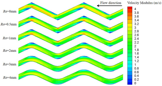
Figure 9.
Velocity modulus for different curvature radii of inserted arc segments.
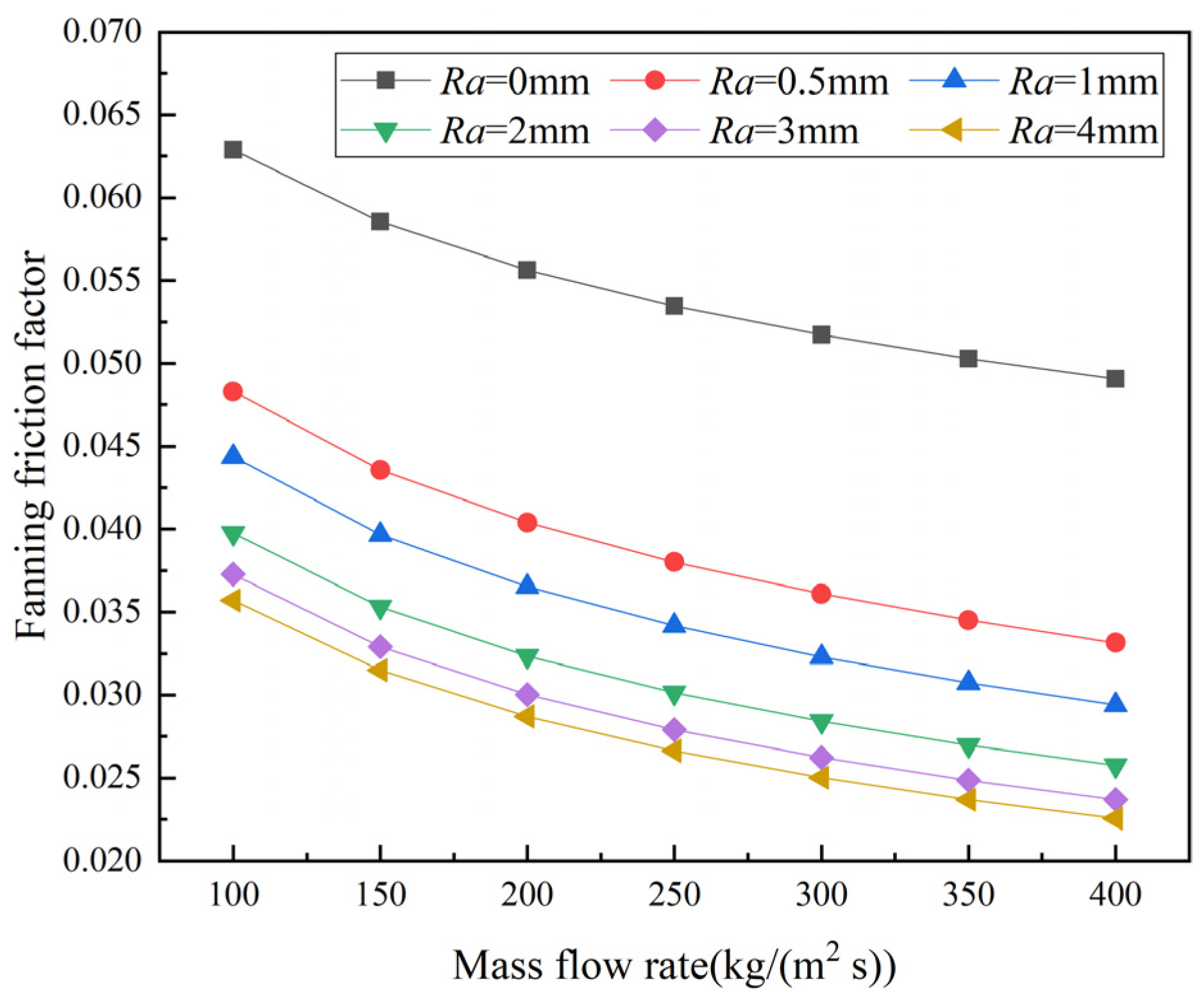
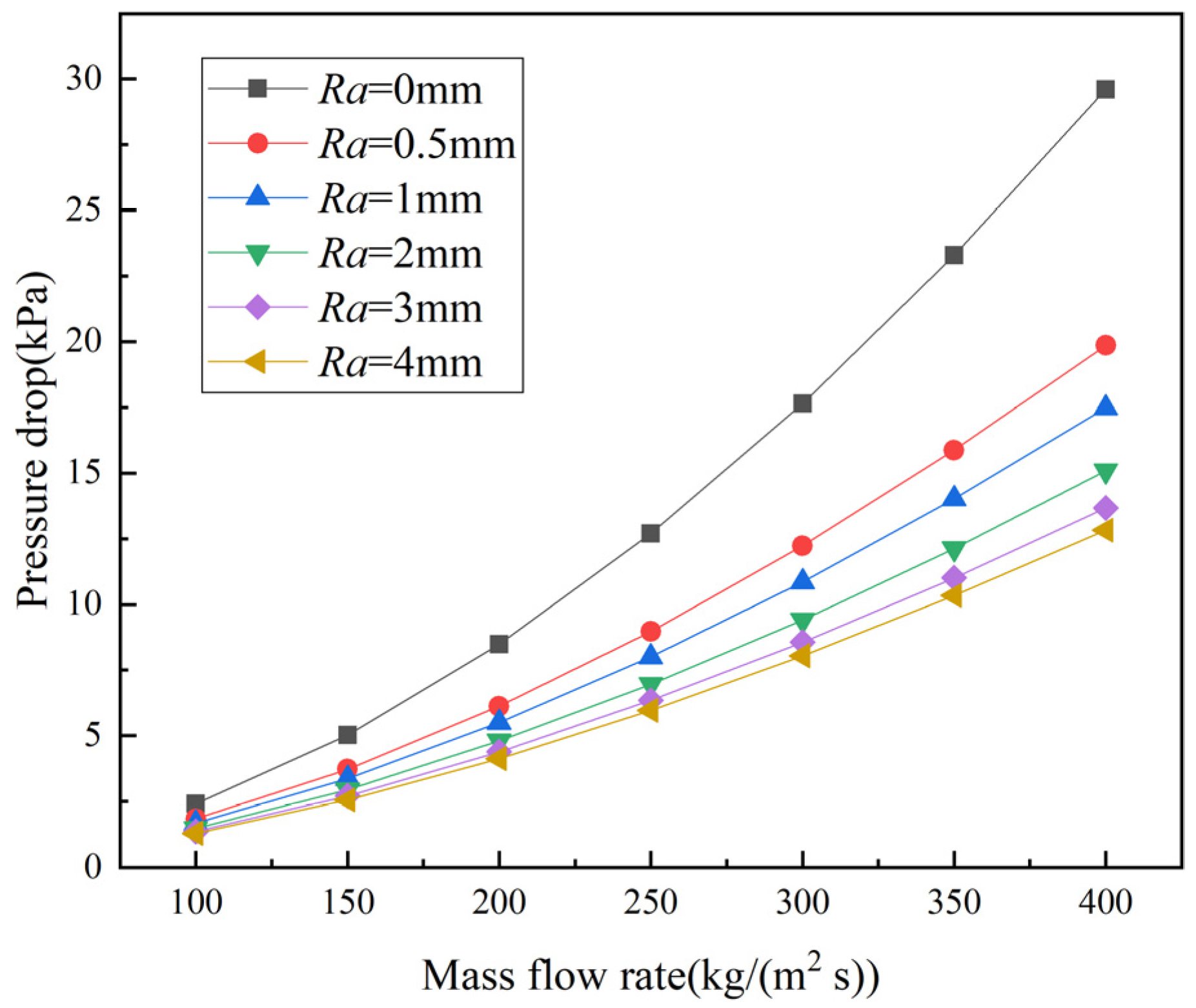
Figure 10 and Figure 11 show the variation in the PCHE friction factor and pressure drop with the mass flow rate when arc segments with different curvature radii are inserted. It can be seen from Figure 10 that the friction factor of the conventional Z-shaped channel is larger than that of the PCHEs with different inserted arc segments under the same mass flow rate. The friction factor of the PCHE with 4 mm arc segments is the smallest, and when the mass flow rate increases from 100 kg/(m2 s) to 400 kg/(m2 s), the friction factor decreases by 36.84%. It can be seen from Figure 11 that the PCHE pressure drop of the channels with inserted arc segments is much smaller than that of the conventional Z-shaped channel PCHE, and the pressure drop decreases with increasing curvature radius of the inserted arc segments. The pressure drop of the PCHE with 4 mm inserted arc segments is the smallest, and the pressure drop is about 46.28–56.68% lower than that of the conventional Z-shaped channel PCHE. The greater the mass flow rate, the greater the pressure drop difference between PCHEs with inserted arc segments of different radii of curvature. The pressure drop of PCHE increases with the increase of mass flow rate. When the mass flow rate is 400 kg/(m2 s), the pressure drop of PCHEs with different structures reaches the maximum. The pressure drop values of PCHEs with inserted arc segments of curvature radii 0.5 mm, 1 mm, 2 mm, 3 mm, and 4 mm are 32.89%, 40.94%, 49.04%, 53.80%, and 56.68% lower, respectively, then that of the conventional Z-shaped channel PCHE.
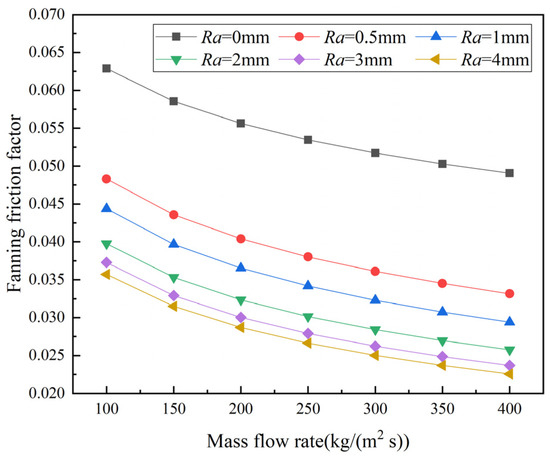
Figure 10.
Fanning friction factor values of PCHEs at different mass flow rates for different curvature radii of inserted arc segments.
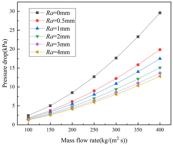
Figure 11.
Pressure drop values of PCHEs at different mass flow rates for different curvature radii of arc segments.
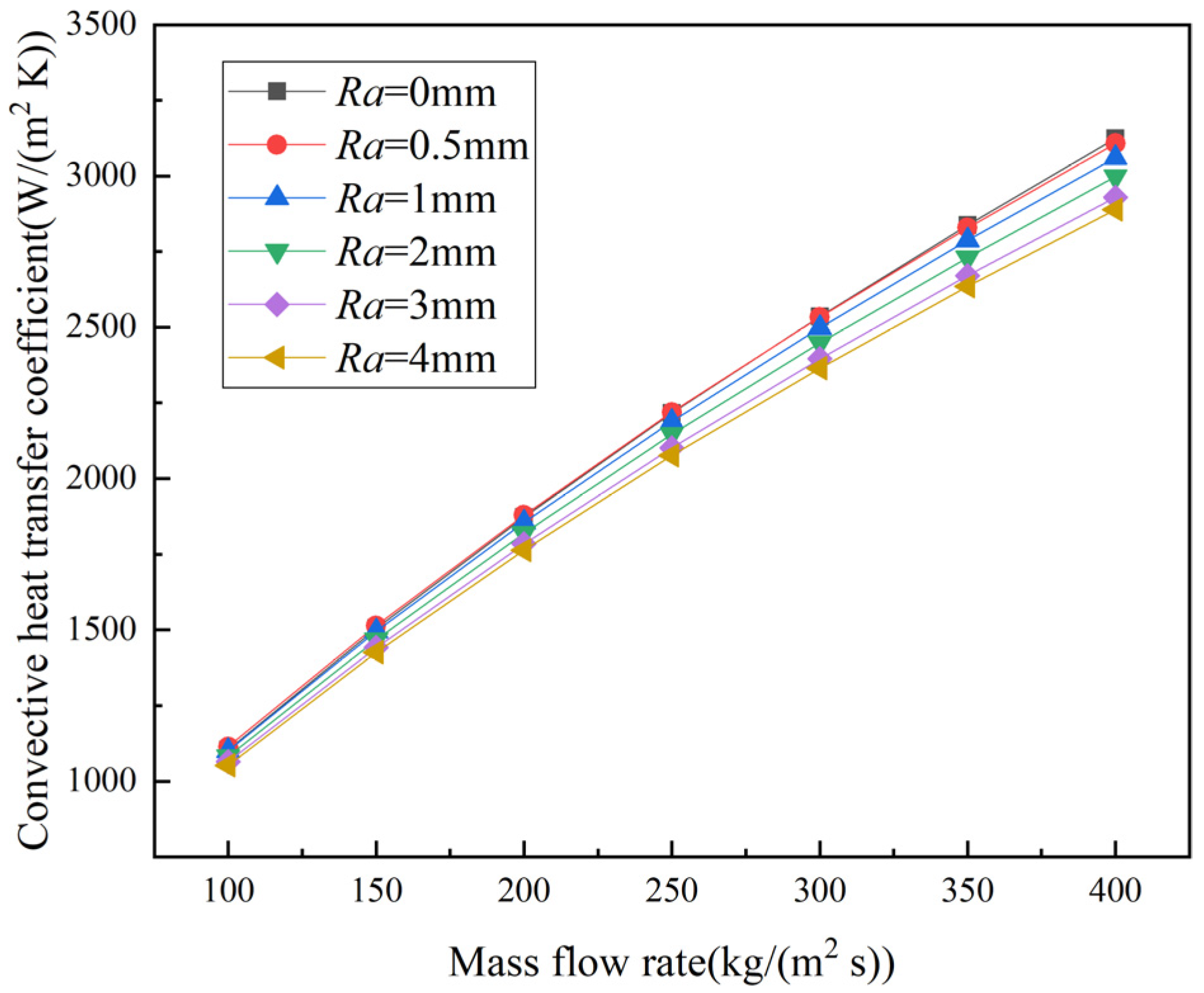
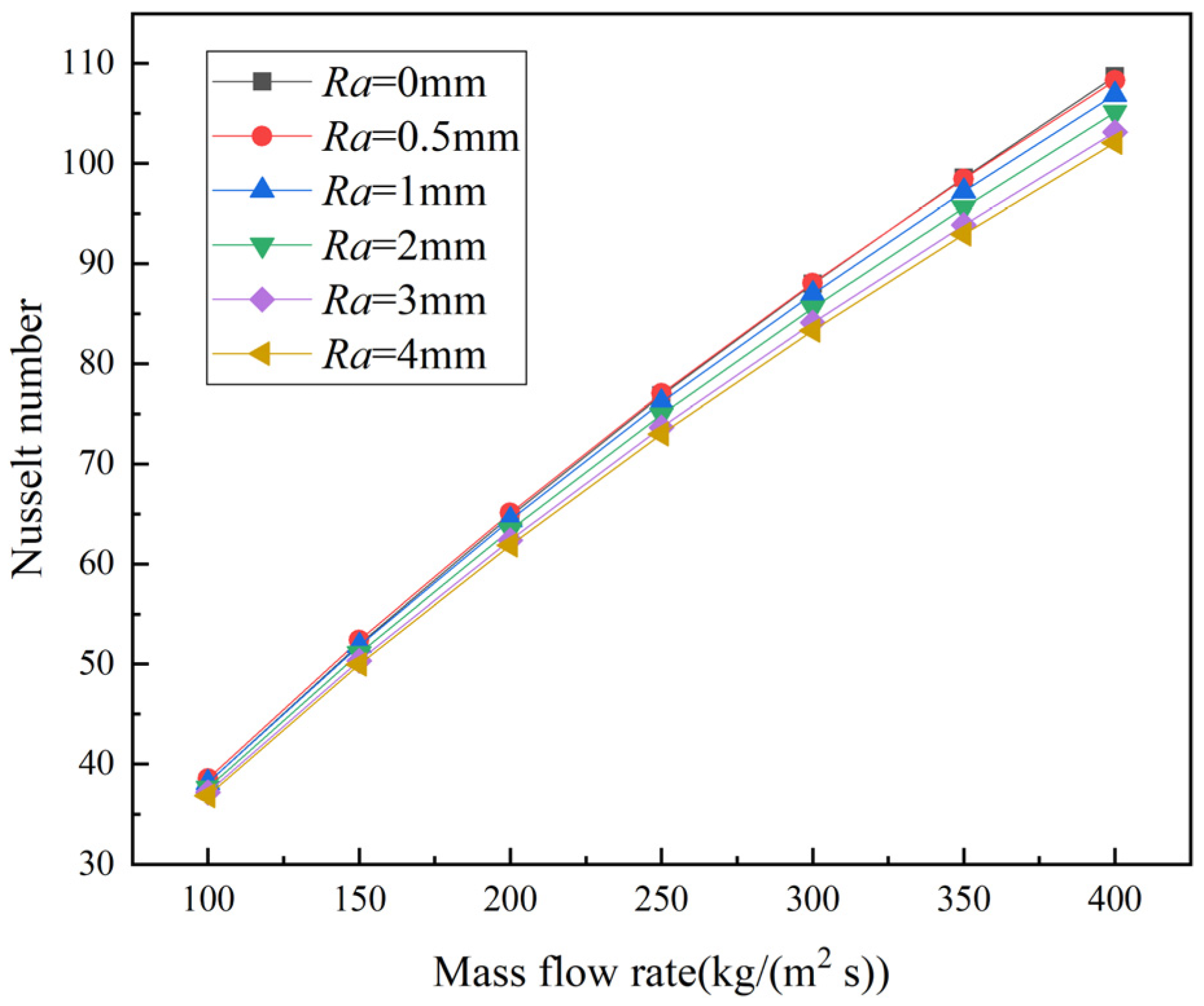
Figure 12 and Figure 13 show the variation in the convective heat transfer coefficient h and Nusselt number Nu with the mass flow rate for inserted arc segments of different curvature radii in PCHEs. When the mass flow rate is low, the convective heat transfer coefficient and Nusselt number of the conventional Z-shaped channel PCHE are not much different from those of the PCHEs with inserted arc segments of different curvature radii. With increasing mass flow rate, the difference in the heat transfer performance between the conventional Z-shaped channel and optimized PCHE increases gradually. For the PCHE channels with 0.5 mm arc segments, the variation curve of the convective heat transfer coefficient with the mass flow rate is basically consistent with that of the conventional Z-shaped channel. The convective heat transfer coefficient of the PCHE with 4 mm arc segments is about 4.65–7.55% lower than that of the conventional Z-shaped channel PCHE.
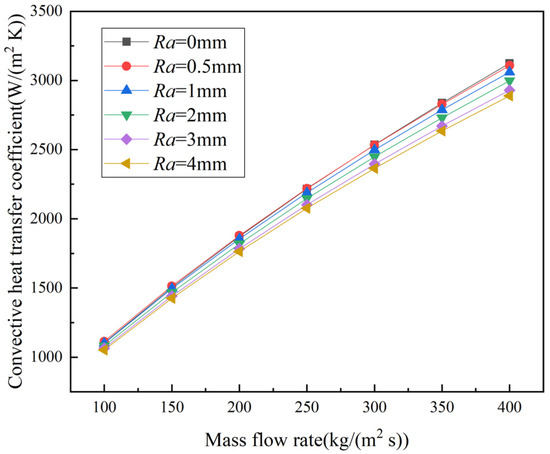
Figure 12.
Convective heat transfer coefficient values of PCHEs at different mass flow rates for different curvature radii of inserted arc segments.
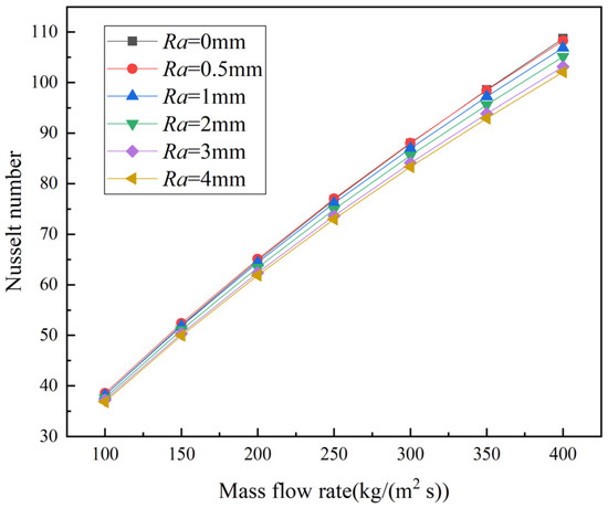
Figure 13.
Nusselt number values of PCHEs at different mass flow rates for different curvature radii of inserted arc segments.
The factors that cause the above results and the differences between the conventional Z-shaped channel PCHEs, the PCHEs with inserted arc segments, and the PCHEs with straight sections are as follows.
Firstly, compared with the conventional Z-shaped channel, the change in the main flow direction at the corner is slowed down, and the velocity distribution in the main flow is more uniform in the channels with increasing inserted arc segments’ curvature radii. Further, the flow channel is shortened after the insertion of arc segments, so the resistance along the way is reduced, and the pressure drop is thus reduced. However, the heat transfer performance is also weakened. Secondly, compared with the PCHEs with inserted straight sections, the S-CO2 obtains a centrifugal force at the corners in the PCHEs with inserted arc segments, and the velocity changes more drastically from one side to the other side. In addition, the average velocity and the areas of fluid in contact with the wall of PCHEs with inserted arc segments are greater. In addition, the fluid flow paths in PCHEs with inserted arc segments are longer than those in the PCHEs with inserted straight sections, and the fluid tends to be more stable in channels with inserted straight sections. In conclusion, the pressure drop for the PCHEs with inserted arc segments at the corners is higher than that of the PCHEs with inserted straight sections, and the heat transfer performance is also better than that of the PCHEs with inserted straight sections.
3.3. Evaluation of the Comprehensive Performance of PCHEs
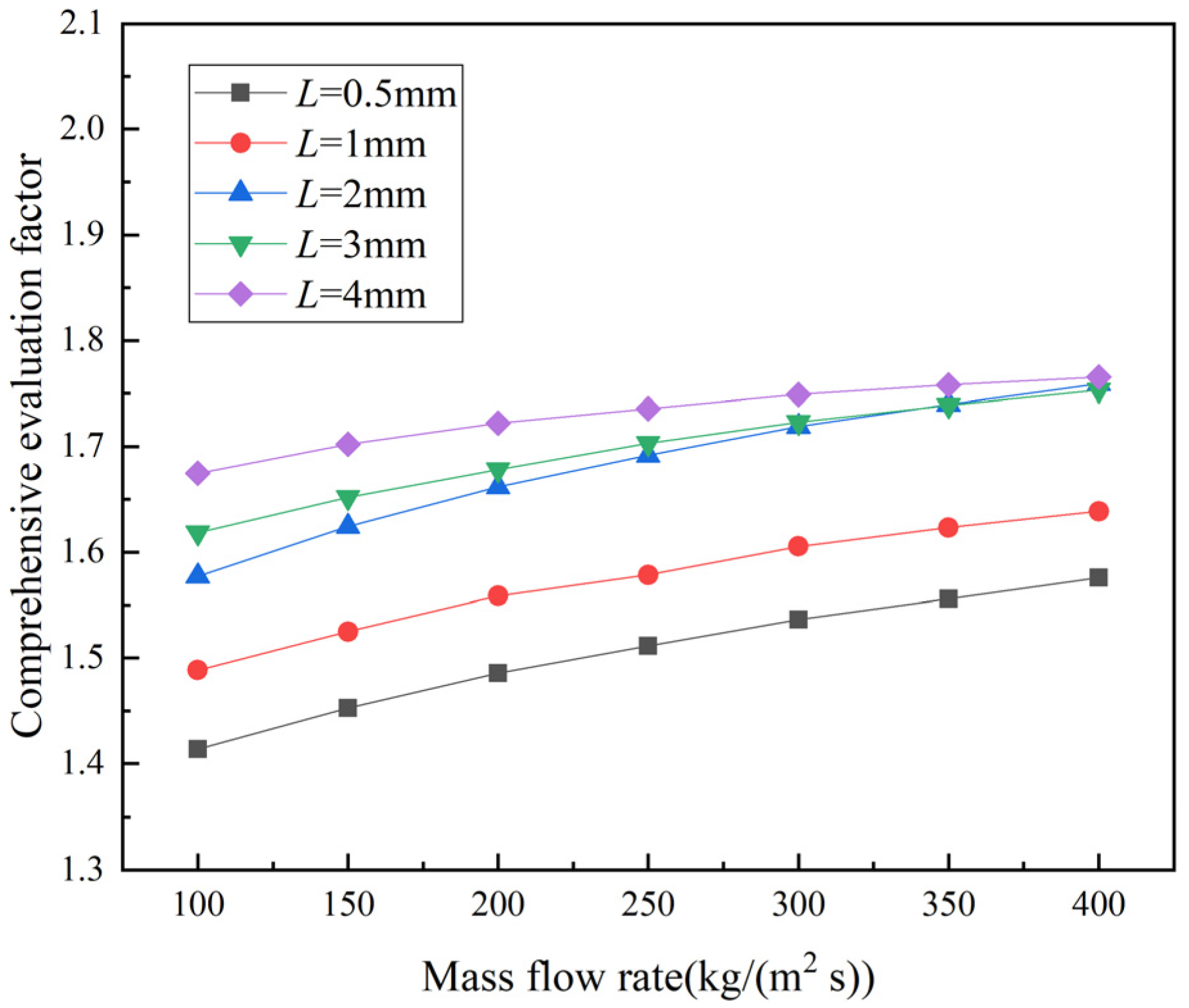
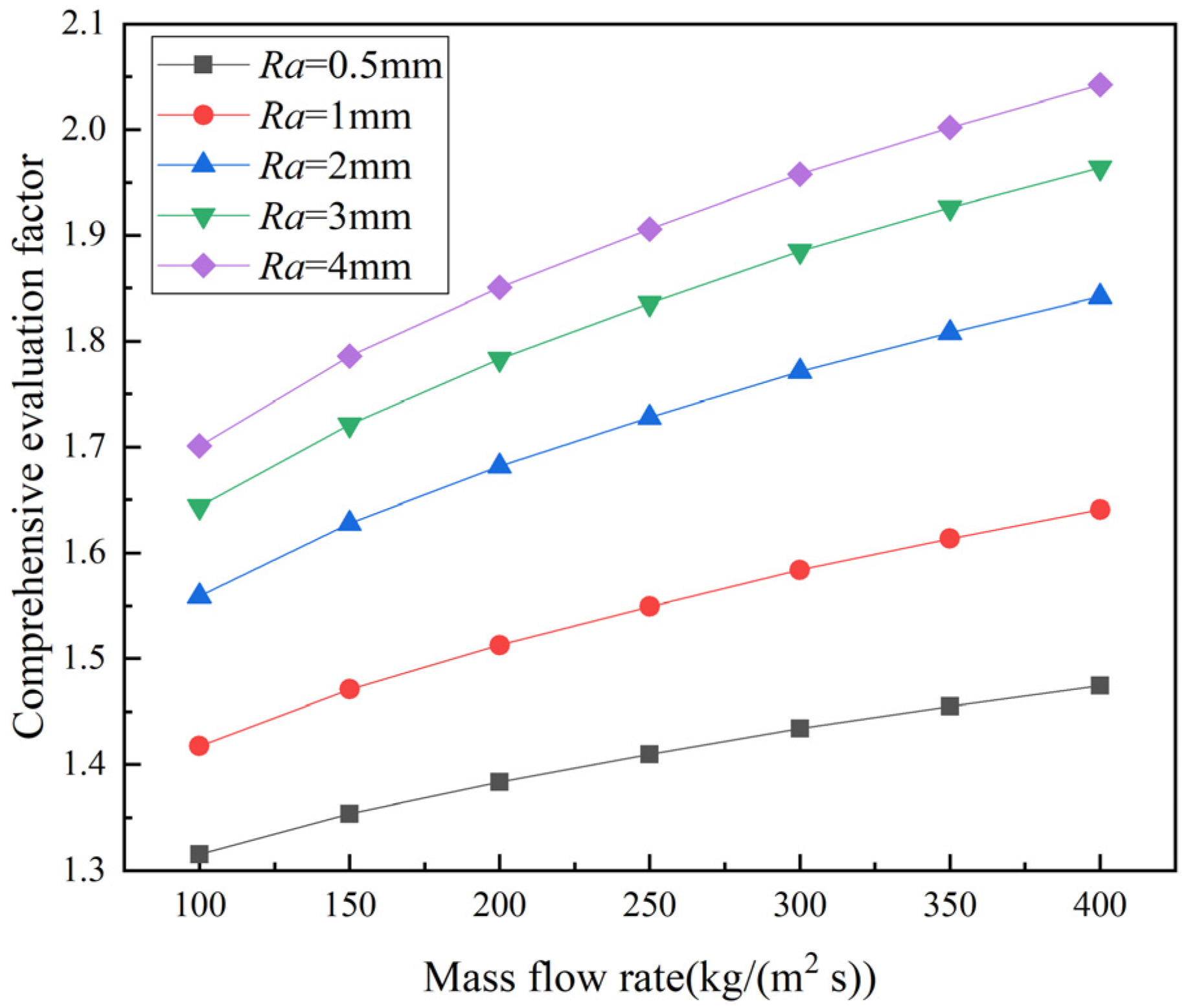
The comprehensive evaluation factor ζ was used to evaluate the performance of PCHEs, and the Nusselt number and friction factor of the conventional Z-shaped channel PCHE were used as benchmarks. Figure 14 and Figure 15 present the comprehensive evaluation factors of PCHEs with different straight sections or arc segments inserted at the corners, respectively. A ζ value greater than 1 indicates that the performance of the optimized PCHEs is better than that of the conventional Z-shaped channel PCHE. When the mass flow rate is in the range of 100–400 kg/(m2 s), the comprehensive evaluation factor increases with increasing mass flow rate, and the increasing trend becomes slower. Figure 14 shows that when PCHEs have inserted straight sections with offset distance 0.5–4 mm, the PCHE with 4 mm straight sections has better comprehensive performance, and the performance of the PCHE with 0.5 mm straight sections is slightly worse. It can be seen from Figure 15 that when the inserted arc segments’ curvature radii are in the range 0.5–4 mm, the ζ value of the PCHE with 4 mm arc segments is the largest. The comprehensive performance of PCHEs with small curvature radii is not as good as that with larger curvature radii. Taking Figure 14 and Figure 15 together, the ζ value of the PCHE with 4 mm straight sections is smaller than that of the PCHE with 4 mm arc segments, indicating that the comprehensive performance of the PCHE with 4 mm arc segments is the best.
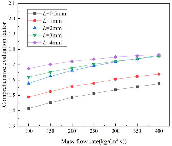
Figure 14.
Comprehensive evaluation factor values of PCHEs at different mass flow rates for different offset distances of inserted straight sections.
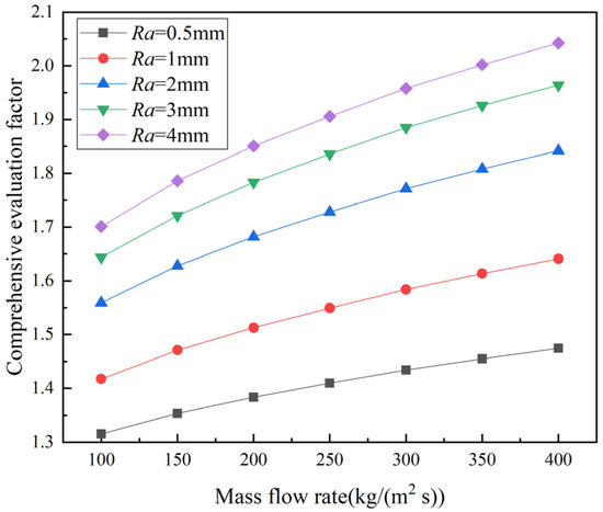
Figure 15.
Comprehensive evaluation factor values of PCHEs at different mass flow rates for different curvature radii of inserted arc segments.
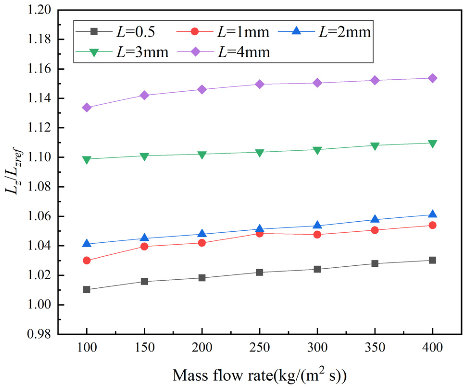
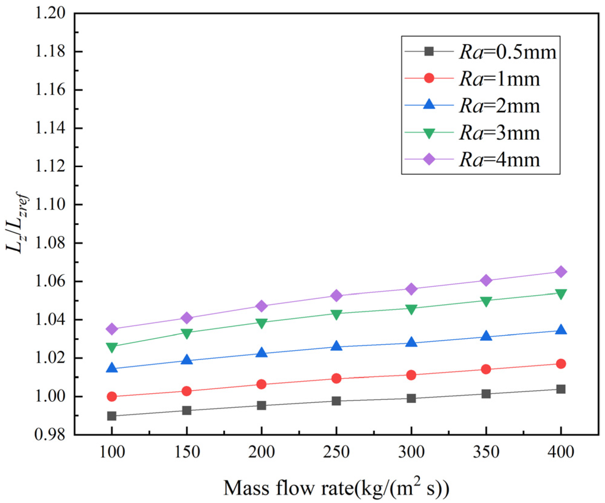
Figure 16 and Figure 17 show the ratios of the total length of the PCHEs with inserted straight sections or arc segments at the corners, respectively, to the conventional Z-shaped channel PCHE. The ratios of the total length are greater than 1, indicating that the total lengths of the optimized PCHE are greater than that of the conventional Z-shaped channel PCHE. Comparing Figure 16 and Figure 17, it can be seen that the ratio of the total length of the PCHE with 4 mm straight sections to the conventional Z-shaped channel PCHE is greater than the ratio of the total length of the PCHE with 4 mm arc segments to the conventional Z-shaped channel PCHE. This means that the structure of the PCHE with 4 mm arc segments is more compact and the manufacturing cost is lower than that of the PCHE with 4 mm straight sections. It can be seen from Figure 14 and Figure 15 that the comprehensive evaluation factors of the optimized channels are larger than that of the conventional Z-shaped channel, which means that the operating cost of the optimized PCHEs is lower than that of the conventional Z-shaped channel PCHE. The PCHE with inserted arc segments of curvature radius 4 mm has the lowest operating cost. In the design process of the heat exchanger, it is necessary to comprehensively consider the operating cost and the manufacturing cost to select the best heat exchanger channel structure. Therefore, the total cost of PCHE with 4 mm arc segments is lower than PCHE with 4 mm straight sections.
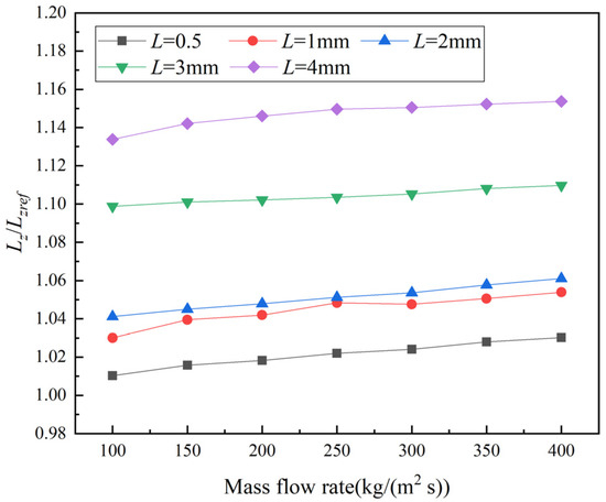
Figure 16.
The ratios of the total length of the PCHE with different offset distances of inserted straight sections to the total length of the Z-shaped PCHE at different mass flow rates.
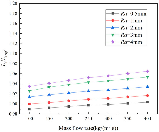
Figure 17.
The ratios of the total length of PCHE with different curvature radii of inserted arc segments to the total length of Z-shaped PCHE at different mass flow rates.
4. Conclusions
In this article, numerical simulation was used to study the effect of inserting straight sections or arc segments at the zigzag corners of a PCHE on its thermal–hydraulic performance when carbon dioxide was used as the working fluid. The thermal–hydraulic performance of the optimized PCHEs was compared with that of the conventional Z-shaped channel. Based on the results above, the following conclusions can be drawn.
- (1)
- With the increase of mass flow rate, the heat transfer performance of PCHEs with different structures is enhanced, and the pressure drop increases.
- (2)
- Under the same mass flow rate, the pressure drop and convective heat transfer coefficient values of the PCHE inserted straight sections are smaller than those of the conventional Z-shaped channel PCHE. As the offset distance of the inserted straight sections increases, the pressure drop of the PCHE decreases, and the heat transfer performance decreases at the same time.
- (3)
- Under the same mass flow rate, the trend of pressure drop and convective heat transfer coefficient of the PCHE inserted arc segments is similar to the PCHE inserted straight sections’. However, the values of pressure drop and convective heat transfer coefficient are higher than those of the PCHE inserted straight sections when the value of the curvature radius is equal to that of the offset distance.
- (4)
- The comprehensive performance of the optimized PCHE models is better than that of the conventional Z-shaped channel PCHE. When the offset distance is 4 mm or the curvature radius is 4 mm, the PCHE inserted straight sections or arc segments has the best comprehensive performance in this research, respectively. Considering the operating cost and the manufacturing cost, it is found that the PCHE with 4 mm arc segments has better economy than the PCHE with 4 mm straight sections.
- (5)
- In this article, the optimization is only carried out under a specific channel diameter and a specific bend angle. Later studies can be carried out in more structures and a wider range of mass flow rates to discover more general laws.
Author Contributions
Conceptualization and supervision, B.W.; formal analysis, investigation and data curation, J.S.; methodology, software and validation, J.C., Y.W., J.S. and B.W.; writing—original draft preparation, J.S. and B.W. All authors have read and agreed to the published version of the manuscript.
Funding
This research received no external funding.
Institutional Review Board Statement
Not applicable.
Informed Consent Statement
Not applicable.
Data Availability Statement
Data involved in this study are available from the authors under a reasonable request.
Conflicts of Interest
The authors declare no conflict of interest.
Nomenclature
| Symbols | |
| A | the pipe wall surface area of fluid flows, m2 |
| Cp | specific heat capacity, J/(kg K) |
| Dh | hydraulic diameter, m |
| f | Fanning friction factor |
| convective heat transfer coefficient, W/(m2 K) | |
| H | height of the solid domain, mm |
| L | offset distances of inserted straight sections, mm |
| Lf | the flow path length of the fluid, m |
| Ls | the single pitch length, mm |
| Lz | the total length of the PCHE, m |
| Nu | Nusselt number |
| ΔPf | the pressure drop of the channel, Pa |
| q | average heat flux, W/m2 |
| R | the radius of channel, mm |
| Ra | curvature radii of inserted arc segments, mm |
| tp | the spacing of the hot and cold channels, mm |
| Tb | average temperature of the fluid, K |
| Tw | wall temperature, K |
| u | the average velocity of effective section in channel, m/s |
| V | the volume of the fluid channel, m3 |
| W | width of the solid domain, mm |
| Greek symbols | |
| α | channel bend angle, ° |
| λ | average thermal conductivity of the fluid, W/(m K) |
| μ | dynamic viscosity of fluid, Pa·s |
| ρ | average density of the fluid, kg/m3 |
| ζ | comprehensive evaluation factor |
| Subscript | |
| ref | the conventional Z-shaped channel PCHE |
References
- Nikitin, K.; Kato, Y.; Ngo, L. Printed circuit heat exchanger thermal-hydraulic performance in supercritical CO2 experimental loop. Int. J. Refrig. 2006, 29, 807–814. [Google Scholar] [CrossRef]
- Aneesh, A.M.; Sharma, A.; Srivastava, A.; Vyas, K.N.; Chaudhuri, P. Thermal-hydraulic characteristics and performance of 3D straight channel based printed circuit heat exchanger. Appl. Therm. Eng. 2016, 98, 474–482. [Google Scholar] [CrossRef]
- Jeon, S.; Baik, Y.J.; Byon, C.; Kim, W. Thermal performance of heterogeneous PCHE for supercritical CO2 energy cycle. Int. J. Heat Mass Transf. 2016, 102, 867–876. [Google Scholar] [CrossRef]
- Kim, I.H.; No, H.C. Physical model development and optimal design of PCHE for intermediate heat exchangers in HTGRs. Nucl. Eng. Des. 2012, 243, 243–250. [Google Scholar] [CrossRef]
- Gao, Y.C.; Xia, W.K.; Long, Y.; Dai, Y.P. Study on the effects of channel width and fin angle on heat transfer and pressure drop of zigzag PCHE. J. Eng. Therm. Energy Power 2019, 34, 94–100. [Google Scholar]
- Lin, Y.S.; Jing, Q.; Xie, Y.H. Numerical investigation on thermal performance and flow characteristics of Z and S shape printed circuit heat exchanger using S-CO2. Therm. Sci. 2019, 23, 757–764. [Google Scholar] [CrossRef] [Green Version]
- Lee, S.M.; Kim, K.Y. A parametric study of the thermal-hydraulic performance of a Zigzag printed circuit heat exchanger. Heat Transf. Eng. 2014, 35, 1192–1200. [Google Scholar] [CrossRef]
- Bartel, N.; Chen, M.; Utgikar, V.P.; Sun, X.; Kim, I.H.; Christensen, R.; Sabharwall, P. Comparative analysis of compact heat exchangers for application as the intermediate heat exchanger for advanced nuclear reactors. Ann. Nucl. Energy 2015, 81, 143–149. [Google Scholar] [CrossRef] [Green Version]
- Cheng, K.Y.; Zhou, J.Z.; Zhang, H.Z.; Huai, X.L.; Guo, J.F. Experimental investigation of thermal-hydraulic characteristics of a printed circuit heat exchanger used as a pre-cooler for the supercritical CO2 Brayton cycle. Appl. Therm. Eng. 2020, 171, 115116. [Google Scholar] [CrossRef]
- Ngo, T.L.; Kato, Y.; Nikitin, K.; Tsuzuki, N. New printed circuit heat exchanger with S-shaped fins for hot water supplier. Exp. Therm. Fluid Sci. 2006, 30, 811–819. [Google Scholar] [CrossRef]
- Pidaparti, S.R.; Anderson, M.H.; Ranjan, D. Experimental investigation of thermal-hydraulic performance of discontinuous fin printed circuit heat exchangers for supercritical CO2 power cycles. Exp. Therm. Fluid Sci. 2019, 106, 119–129. [Google Scholar] [CrossRef]
- Tang, L.H.; Cui, L.; Sunden, B. Optimization of fin configurations and layouts in a printed circuit heat exchanger for supercritical liquefied natural gas near the pseudo-critical temperature. Appl. Therm. Eng. 2020, 172, 115131. [Google Scholar] [CrossRef]
- Kim, D.E.; Kim, M.H.; Cha, J.E.; Kim, S.O. Numerical investigation on thermal-hydraulic performance of new printed circuit heat exchanger model. Nucl. Eng. Des. 2008, 238, 3269–3276. [Google Scholar] [CrossRef]
- Zhang, H.Z.; Cheng, K.Y.; Huai, X.L.; Zhou, J.Z.; Guo, J.F. Experimental and numerical study of an 80-kW Zigzag printed circuit heat exchanger for supercritical CO2 Brayton cycle. J. Therm. Sci. 2021, 30, 1289–1301. [Google Scholar] [CrossRef]
- Kim, I.H.; No, H.C.; Lee, J.I.; Jeon, B.G. Thermal hydraulic performance analysis of the printed circuit heat exchanger using a helium test facility and CFD simulations. Nucl. Eng. Des. 2012, 239, 2399–2408. [Google Scholar] [CrossRef]

Publisher’s Note: MDPI stays neutral with regard to jurisdictional claims in published maps and institutional affiliations. |
© 2022 by the authors. Licensee MDPI, Basel, Switzerland. This article is an open access article distributed under the terms and conditions of the Creative Commons Attribution (CC BY) license (https://creativecommons.org/licenses/by/4.0/).