Abstract
This manuscript describes the operation of a droop-based controller for three-phase converters in the case of the absence of a neutral connection to the grid. The controller is capable of output power tracking and smooth transitions into the islanded operation. While independent per-phase control of the converter output power is possible if a neutral connection is present, its absence implies additional constraints to be considered. Focusing on this latter case, the controller described herein allows the independent control of the active power at the output of each phase of the converter and a smooth transition to the islanded operation. These features are paramount in future smart power systems, such as smart microgrids, for implementing demand–response, power-flow management, and uninterrupted power operation.
1. Introduction
Microgrids integrating distributed energy resources connected to the AC grid by means of electronic power converters (EPCs) should support a number of features [1,2]. The capability of flexibly controlling the exchanged active and reactive power, that is, the output power control, and the capability of islanded operation are some of the important functionalities in scenarios such as the one represented in Figure 1. Output power control is crucial for the implementation of demand–response and for unbalanced compensation in three-phase systems [3,4]. Islanded operation is crucial to make the microgrid subsystem resilient against the adverse events affecting the main power system [5].
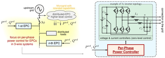
Figure 1.
Microgrid scenario in which distributed electronic power converters (EPCs) track defined power references and are capable of sustaining the operation of the microgrid in case of disconnection from the upstream grid (i.e., islanding). The control of 3-3w EPCs is considered herein.
Solutions such as the per-phase power control in [6] limited to three-phase four-wires (i.e., 3-4w) systems allow the control of the output power of grid-connected inverters and also permit their transition to the islanded operation. Considering other relevant solutions described in the literature, such as [7,8,9,10], the per-phase control can harmoniously integrate multiple merits, in terms of (i) independent output power control for each phase of a three-phase four-wire grid-connected inverter, (ii) smooth transitions into the islanded operation mode, (iii) operation in islanded conditions, even when multiple parallel-connected EPCs integrating the proposed controller are present. The solution described herein integrates the features indicated above and, in addition, it allows operation in case of the absence of a neutral connection, that is, in 3-3w systems. This latter configuration is relevant in low-voltage grid scenarios, as shown in some European low-voltage distribution benchmarks [11], and also considered in recent research papers in the field, such as [12,13,14].
To highlight the features of the presented solution, a comparison with other control approaches is given in Table 1. Grid-feeding converters, for example, require the presence of the main grid or, in order to operate in an islanded microgrid of other voltage-forming units [15]. Traditional droop control using P–f and Q–V droop laws allows islanded operation; however, the regulation of the total active and reactive power (i.e., power tracking) during grid-tied operation is achievable only by control adaptations, as shown in [14,16,17]. In [17], indicated as a droop with a 3P&Q track in Table 1, the tracking of the total three-phase inverter output power and a smooth transition to the islanded operation is achieved and shown; however, per-phase power regulation is left unexplored. In fact, it is impossible to independently impose droop laws on each phase, as this would result in different frequencies at the different phases of the three-phase system. The approach analyzed herein allows all the functionalities reported above and indicated in Table 1, but it was exclusively presented in [6] and only restricted to the case of three-phase four-wire (i.e., 3-4w) networks.

Table 1.
Comparison with other approaches.
While operation with a neutral connection is of significant importance and gives full flexibility for output power control [10,18,19,20], the case without a neutral connection is still of interest and can be commonly found in grid-tied applications [21,22,23]. For this latter case originally considered herein, the independent, phase-by-phase control of the output active and reactive power, which results in six variables in total, is not possible, and only a subset of the output powers can be controlled instead. As shown here, four variables can be controlled in three-wire systems and exploited, for example, for balancing distributed power or for control needs of local distribution system operators or microgrid controllers [24,25], as recommended in modern microgrid standards [26].
This manuscript discusses and proposes the per-phase power control of three-phase inverters without a neutral connection to the grid, as displayed in the representative configuration in Figure 2. This kind of operation without neutral connections has been foreseen in [6], anticipating the need for dedicated studies and discussions for this extension, which are then presented in this study. Specifically, in Section 2, the basics of active and reactive power flow are overviewed for both three-phase four-wire and three-phase three-wire systems, highlighting the additional constraint and related reduced control flexibility present in this latter case. The per-phase power control for three-phase three-wire systems proposed herein is then described in Section 3. Section 4 demonstrates the behavior of the control in a couple of practical conditions. Finally, Section 5 concludes the paper.
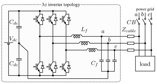
Figure 2.
An electronic power converter (EPC) connected to a three-phase low-voltage network without a neutral connection (i.e., three-phase three-wire connection, 3-3w) whose per-phase output power control is proposed in this study.
2. Basics of Power Control
2.1. Three-Phase Four-Wire (3-4w) Networks
The power exchange of a single-phase inverter connected to the grid is now considered, which is helpful as a preliminary analysis for setting the nomenclature and overviewing some key relations. Assume is the phasor of the inverter output voltage, and is the grid voltage phasor. Considering Thevenin’s inverter model, namely, a voltage generator with its equivalent series impedance, connected to the grid, the equations describing the flow of the active power and the reactive power among the two equivalent generators can be derived. Assuming the grid frequency , the interconnection impedances being mainly inductive, and small voltage and phase differences, the following linearized relations yield [27,28]:
with L and L. Such relations hold for each of the phases of a 3-4w connection. In this case, there is no interdependence between the phases, which means that the output power at a phase does not affect the output powers measured at the other phases. This is not the case in 3-3w connections, which are addressed herein.
2.2. Three-Phase Three-Wire (3-3w) Networks
Consider the 3-3w connection of Figure 3 with the indicated nomenclature for voltage phasors. In this case, fully independent power control is not physically possible; that is, the power exchanged by one generator is affected by the phase and voltage differences imposed by the others, which is the neutral point voltage , under the hypothesis of a symmetric grid voltage.
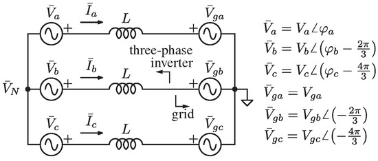
Figure 3.
Thevenin model of a grid-tied three-phase three-wire inverter.
The linearized relations (1) derived from the model in Figure 3 yield:
where vectors and , with , and M the matrix defined as
The rank of is four, which is the number of variables that can be regulated arbitrarily. On this basis, for a 3-3w connection, it is not possible to regulate all of the six active and reactive powers of the phases a, b, and c at the same time, as it is possible with a 3-4w connection instead [6]. A possible choice of variables to be controlled for output power tracking may be , , , , or, equivalently, , , , . This latter option is considered herein, yielding
To avoid the control actions related to homopolar components, which are not controlled by using this approach, such components can be removed by processing the voltage measurements with a decoupling matrix (such as the one used in (8)).
3. Per-Phase Power Control in Three-Phase Three-Wire Systems
The block diagram of the proposed controller is displayed in Figure 4. On the top, a P–f droop relation processes the total three-phase power exchanged at the inverter output and provides the phase , which is the integral of the angular frequency given by the droop characteristic:
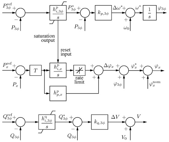
Figure 4.
Per-phase power controller. As shown at the top, synchronization branch provides a reference angle to the three phases, represented by the generic symbol x (i.e., a, b, c). The angle and amplitude of each phase are adjusted for per-phase power control. The resulting references are given to EPC current and voltage regulators (zero-level control) for output voltage control.
In this way, the droop-controlled converter can synchronize to the grid voltage, keeping the known synchronization characteristics of the P–f droop, as shown, for example, in [29]. The top branch in Figure 4 is referred to as the synchronization branch in the following. Then, two different behaviors are established: grid-connected and islanded operation.
3.1. Grid-Connected Operation
During a grid-connected operation, output power tracking is possible due to the presence of the main grid [30]. The total is adjusted using a three-phase power regulator:
whose output modifies the total three-phase output power of the inverter, by shifting the droop characteristic (5).
To achieve the output power tracking of controllable quantities , , , and , the obtained is then adjusted phase-by-phase, as displayed by the central blocks in Figure 4 referring to the generic x-th phase. Here a proportional-integral controller denoted as
produces the phase shift that adds to the instantaneous three-phase angle and allows the phase power to follow the respective reference power during grid-tied operation. In order to decouple the balanced active power control and unbalanced power control, making the first component relevant only to the top, the synchronization loop, it is possible to use a decoupling matrix T to remove the balanced terms from the per-phase control loop. The matrix can be defined as follows:
Finally, the total delivered output reactive power is adjusted by acting on the amplitude of the generated three-phase voltages, using the following regulator:
3.2. Islanded Operation
During islanded operation, the generated and dissipated power must be exactly equal within an islanded subsystem; then, a transition into islanded operation makes output power control no more possible and automatically leads the power regulator into saturation. Consistently, the integral part of the per-phase regulator is also disabled. The saturation limits , or can be designed as discussed in [6]. Remarkably, during the islanded mode of operation, the controller behaves as a traditional droop controller, through which the converter frequency changes linearly with the total delivered three-phase power:
where is a constant saturation limit, namely, or . In the same way, the reactive power controller also saturates
leading the control to operate as a traditional droop scheme with a smooth transition to the islanded operation.
As a final remark, even though some fundamental relations such as (6), (7), (9), and (10) are also used for control with 3-3w systems, the characteristics of the control problem highlighted in (2) and the controller organization derived from (4) and discussed by referring to Figure 4 require substantial modifications on the control scheme presented for 3-4w systems in [6], which can not be used in the case of the absence of neutral wires.
4. Validation Results
The proposed controller was tested with simulation and by means of a laboratory-scale experimental prototype implementing the system in Figure 2. The system parameters related to the EPC hardware and control are listed in Table 2. The control technique in Figure 4 was deployed in a B-Box controller manufactured by Imperix Ltd., through which the EPC controller was implemented. The EPC hardware was implemented by using three modules PEB8032 manufactured by Imperix Ltd., and the grid voltage was generated by using a three-phase voltage source implemented with three additional modules of the same type. A photo of the used experimental setup is displayed in Figure 5.
Table 2.
Inverters (EPCs) and control parameters.
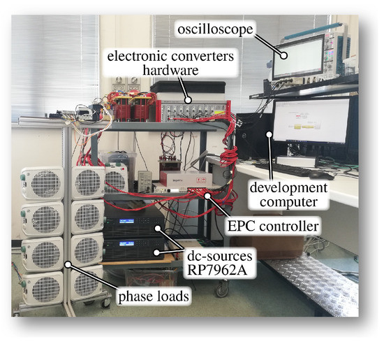
Figure 5.
Photo of the experimental setup used to validate the proposed approach implementing the configuration displayed in Figure 2.
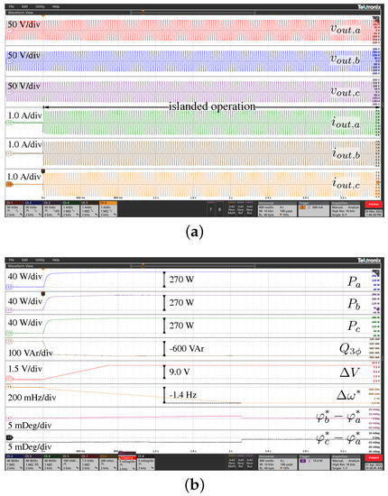
Figure 6 and Figure 7 display the most significant experimental waveforms to show the chief features of the control. The instantaneous three-phase voltages and currents are reported in subfigure (a), while subfigure (b) displays the related active power , , and and reactive power , the voltage amplitudes deviation , the frequency deviation , and the phase displacement with respect to the first phase (i.e., and ). The results are discussed next.
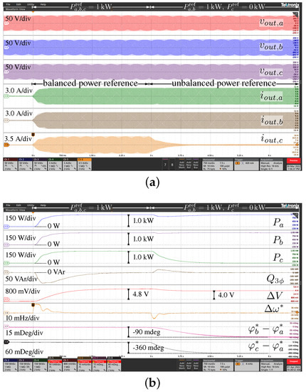
4.1. Balanced and Unbalanced Power Reference Variations
Figure 6a,b show the response of the system to a power reference step change. Specifically, the response to a balanced reference step change is shown first. Then, a subsequent transient is displayed in which phase-c is solely subject to a reference change , making the system’s operation unbalanced. The total requested reactive power reference is kept fixed at zero. Figure 6b demonstrates the expected transient in terms of active and reactive power, with zero steady-state tracking errors. As expected, during balanced power reference tracking, phase displacements and are not affected by balanced power references, as they are the necessary phase-shift to allow the desired active power exchange the same in the three phases and included in variations in the instantaneous phase related to the integral of the shown . Moreover, in this transient, the decoupling matrix T in (8) prevents any reaction of the per-phase control loops involving . Some voltage variations can be noticed as a secondary effect, due to the residual resistive components of the interconnection impedance between the inverter and the grid of the experimental setup. The following unbalanced transient stimulates the reaction of the per-phase control loops, which introduces the required phase deviation in order to allow the unbalance power flow at phase-c. Due to the decoupling matrix T, which prevents the per-phase loops from regulating balanced power terms, variation in the resulting total power and balanced power stimulates the response of the synchronization loop too. This results in a transient variation in the instantaneous frequency , which gives the instantaneous phase and a corresponding further adjustment of .
4.2. Transition of Grid-Tied to Islanded Operation
Figure 7a,b show the response of the system to a sudden disconnection from the main grid, namely, a transition to the islanded operation. In this test, the local load is balanced, composed of three 50- resistors in parallel with three 50- capacitors, star-connected at the output of the inverter. At the opening of the circuit breaker , in Figure 2, the proposed controller is capable of maintaining the local voltage, without any discontinuity in the supply of the load. Due to the absence of the main grid, ensuring the balance between power generation and absorption, i.e., power tracking, makes the active and reactive power regulators deviate toward the set saturation limits. Notably, this does not impact the quality of the supplied voltage, producing voltage deviations and frequency deviations that are within tolerable limits by design. Based on the parameters in Table 2, the range of the operating frequency of the islanded microgrid falls within – [17].
Commonly, in droop control, static P–f characteristics are also represented. The trajectory on the P–f plane during the considered transition to the islanded operation is displayed in Figure 8. Some representative points are reported: A corresponds to the operation during grid-connected operation, B and C are points during the transition toward the islanded operation mode, and D is the point of operation during the islanded mode. The speed of change in the operating point during the transition, which is explicit in the representation of quantities in the time domain in Figure 7, is qualitatively indicated in Figure 8 in the colored trajectory, from fast, shown in red, to slow, shown in blue.
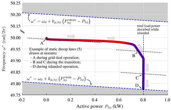
Figure 8.
Representation of the trajectory on the f–P plane during the transition shown in Figure 7, with total equivalent load in islanded operation of . Colored dashed lines indicate the limits (10). The speed of change in operating point is qualitatively indicated in color on the trajectory: fast changes in red and slow changes in blue.
4.3. Example of Application
The proposed approach allows the transition to the islanded operation and also allows power tracking during grid-tied operation, which was experimentally verified in the previous section. An example of a practical application of the latter feature of output power tracking is now further demonstrated by simulation results in Figure 9, in which the objective is to provide unbalanced power compensation at the interface with the main grid, in scenarios such as those outlined in the introduction (see, for example, Figure 1). In general, power control and the capability of allowing distributed unbalanced compensation are the available ancillary services within modern electricity grids [1,2,12].
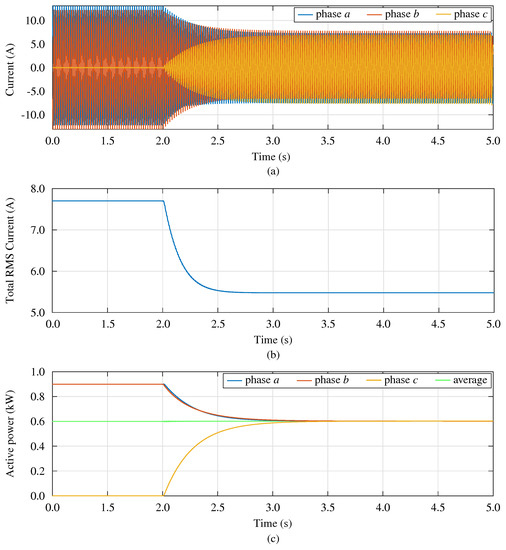
Figure 9.
Example of application: unbalanced compensation at the interface with the main grid: (a) currents at the interface with the main grid with related total rms currents in (b); (c) active powers phase-by-phase at the interface with the grid with related average.
This is shown in Figure 9 considering the unbalanced compensation in the configuration in Figure 2, where an unbalanced load is locally connected. The load consists of a resistive load connected between phase a and phase b. A grid impedance of is considered. Initially, the per-phase power references are equal to zero, so the grid is completely supplying the unbalanced load. At , the inverter received new power reference signals, in order to compensate for the unbalance. These references may be computed, for example, using a higher-level control layer implementing grid services, as contemplated in Figure 1 and envisioned in recent studies such as [2,12,25]. Notice that the total active power supplied by the inverter is still zero, but now the per-phase power is such that the unbalance component of the load is entirely supplied by the inverter; thus, the current absorbed by the grid becomes a balanced current. The total rms current at the interface with the grid significantly reduces owing to the control, which is beneficial considering grid losses and stresses.
5. Conclusions
In this study, a controller achieving output power reference tracking at the phases of inverters connected to three-phase three-wire electrical systems was described and demonstrated. In three-phase three-wire systems, it is not possible to independently control the active and reactive power of all three phases of the converter; thus, a suitable control scheme is required to accommodate the requirements of power flow control, which are crucial in advanced power systems and the limited degrees of freedom due to the absence of neutral wires. In addition, the capability of maintaining uninterrupted operation in case of disconnection from the main grid is also of paramount importance in microgrids. The experimental validation showed that the proposed controller succeeds in harmoniously integrating phase-by-phase output power tracking and the capability of a smooth transition to the islanded operation.
Author Contributions
Conceptualization, T.C. and A.L.; methodology, A.L. and T.C.; software, H.A. and A.L.; validation, A.L., H.A. and D.B.; formal analysis, A.L.; investigation, A.L.; resources, T.C. and P.M.; writing—original draft preparation, A.L.; writing—review and editing, T.C. and D.B.; visualization, T.C.; supervision, T.C.; project administration, T.C.; funding acquisition, P.M. All authors have read and agreed to the published version of the manuscript.
Funding
This research was funded by the Department of Management and Engineering, DTG, University of Padova.
Informed Consent Statement
Not applicable.
Data Availability Statement
The data presented in this study are available on request from the corresponding author.
Conflicts of Interest
The authors declare no conflict of interest. The funders had no role in the design of the study; in the collection, analyses, or interpretation of data; in the writing of the manuscript; or in the decision to publish the results.
References
- Xu, S.; Xue, Y.; Chang, L. Review of Power System Support Functions for Inverter-Based Distributed Energy Resources- Standards, Control Algorithms, and Trends. IEEE Open J. Power Electron. 2021, 2, 88–105. [Google Scholar] [CrossRef]
- Alazemi, T.; Darwish, M.; Radi, M. TSO/DSO Coordination for RES Integration: A Systematic Literature Review. Energies 2022, 15, 7312. [Google Scholar] [CrossRef]
- Simmini, F.; Agostini, M.; Coppo, M.; Caldognetto, T.; Cervi, A.; Lain, F.; Carli, R.; Turri, R.; Tenti, P. Leveraging Demand Flexibility by Exploiting Prosumer Response to Price Signals in Microgrids. Energies 2020, 13, 3078. [Google Scholar] [CrossRef]
- Abedini, H.; Caldognetto, T.; Mattavelli, P.; Tenti, P. Real-Time Validation of Power Flow Control Method for Enhanced Operation of Microgrids. Energies 2020, 13, 5959. [Google Scholar] [CrossRef]
- Hamidieh, M.; Ghassemi, M. Microgrids and Resilience: A Review. IEEE Access 2022, 10, 106059–106080. [Google Scholar] [CrossRef]
- Caldognetto, T.; Abedini, H.; Mattavelli, P. A Per-Phase Power Controller for Smooth Transitions to Islanded Operation. IEEE Open J. Power Electron. 2021, 2, 636–646. [Google Scholar] [CrossRef]
- Espina, E.; Espinoza, M.; Cárdenas, R. Active power angle droop control per phase for unbalanced 4-wire microgrids. In Proceedings of the 2017 IEEE Southern Power Electronics Conference (SPEC), Puerto Varas, Chile, 4–7 December 2017; pp. 1–6. [Google Scholar] [CrossRef]
- Liu, B.; Liu, Z.; Liu, J.; An, R.; Zheng, H.; Shi, Y. An Adaptive Virtual Impedance Control Scheme Based on Small-AC-Signal Injection for Unbalanced and Harmonic Power Sharing in Islanded Microgrids. IEEE Trans. Power Electron. 2019, 34, 12333–12355. [Google Scholar] [CrossRef]
- Fazeli, S.M.; Ping, H.W.; Rahim, N.B.A.; Ooi, B.T. Individual-phase control of 3-phase 4-wire voltage–source converter. IET Power Electron. 2014, 7, 2354–2364. [Google Scholar] [CrossRef]
- Hsu, H.C.; Chung, N.T.; Chen, Y.M.; Hsu, C.C. Grid Voltage Balancing Strategy Based on Per-Phase-Controlled Inverters. In Proceedings of the 2021 IEEE International Future Energy Electronics Conference (IFEEC), Taipei, Taiwan, 16–19 November 2021; pp. 1–6. [Google Scholar] [CrossRef]
- CIGRE Task Force C6.04.02. Benchmark Systems for Network Integration of Renewable and Distributed Energy Resources; Technical Report; International Council on Large Electric Systems: Paris, France, 2014. [Google Scholar]
- Das, H.S.; Nurunnabi, M.; Salem, M.; Li, S.; Rahman, M.M. Utilization of Electric Vehicle Grid Integration System for Power Grid Ancillary Services. Energies 2022, 15, 8623. [Google Scholar] [CrossRef]
- Sufyan, A.; Jamil, M.; Ghafoor, S.; Awais, Q.; Ahmad, H.A.; Khan, A.A.; Abouobaida, H. A Robust Nonlinear Sliding Mode Controller for a Three-Phase Grid-Connected Inverter with an LCL Filter. Energies 2022, 15, 9428. [Google Scholar] [CrossRef]
- Madadi, M.; Zou, K.; Bhattacharya, S. Unified Control Method for Seamless Transition of a Weak Grid Connected AC Microgrid to Islanded Mode. In Proceedings of the 2022 IEEE Energy Conversion Congress and Exposition (ECCE), Detroit, MI, USA, 9–13 October 2022; pp. 1–8. [Google Scholar] [CrossRef]
- Timbus, A.; Liserre, M.; Teodorescu, R.; Rodriguez, P.; Blaabjerg, F. Evaluation of Current Controllers for Distributed Power Generation Systems. IEEE Trans. Power Electron. 2009, 24, 654–664. [Google Scholar] [CrossRef]
- Guerrero, J.M.; Vasquez, J.C.; Matas, J.; de Vicuna, L.G.; Castilla, M. Hierarchical Control of Droop-Controlled AC and DC Microgrids—A General Approach Toward Standardization. IEEE Trans. Ind. Electron. 2011, 58, 158–172. [Google Scholar] [CrossRef]
- Lissandron, S.; Mattavelli, P. A controller for the smooth transition from grid-connected to autonomous operation mode. In Proceedings of the 2014 IEEE Energy Conversion Congress & Exposition (ECCE), Pittsburgh, PA, USA, 14–18 September 2014; pp. 4298–4305. [Google Scholar] [CrossRef]
- Ivanov, O.; Neagu, B.C.; Niţu, A.I.; Gavrilaş, M. An Improved Metaheuristic Algorithm for Load Balancing in LV Distribution Networks. In Proceedings of the 2021 9th International Conference on Modern Power Systems (MPS), Cluj-Napoca, Romania, 16–17 June 2021; pp. 1–5. [Google Scholar] [CrossRef]
- Ivanov, O.; Neagu, B.C.; Cibotărică, A.; Gavrilaş, M. Multiobjective Prosumer Surplus Management for Optimal Microgrid Operation. In Proceedings of the 2021 10th International Conference on Energy & Environment (CIEM), Bucharest, Romania, 14–15 October 2021; pp. 1–5. [Google Scholar] [CrossRef]
- Hadjidemetriou, L.; Charalambous, A.; Kyriakides, E. Control Scheme for Phase Balancing of Low-Voltage Distribution Grids. In Proceedings of the 2019 International Conf. Smart Energy Systems and Technologies (SEST), Porto, Portugal, 9–11 September 2019; pp. 1–6. [Google Scholar] [CrossRef]
- Guan, S.; Tao, S.; Song, Y. Application research of IEEE Std.1459–20 10 in three-phase three-wire system. In Proceedings of the 2022 IEEE 6th Information Technology and Mechatronics Engineering Conference (ITOEC), Chongqing, China, 4–6 March 2022; Volume 6, pp. 511–515. [Google Scholar] [CrossRef]
- Brandao, D.I.; Araujo, L.S.; Alonso, A.M.S.; dos Reis, G.L.; Liberado, E.V.; Marafão, F.P. Coordinated Control of Distributed Three- and Single-Phase Inverters Connected to Three-Phase Three-Wire Microgrids. IEEE Trans. Emerg. Sel. Topics Power Electron. 2020, 8, 3861–3877. [Google Scholar] [CrossRef]
- Burgos-Mellado, C.; Llanos, J.; Espina, E.; Sáez, D.; Cárdenas, R.; Sumner, M.; Watson, A. Single-Phase Consensus-Based Control for Regulating Voltage and Sharing Unbalanced Currents in 3-Wire Isolated AC Microgrids. IEEE Access 2020, 8, 164882–164898. [Google Scholar] [CrossRef]
- Brandao, D.I.; Caldognetto, T.; Marafão, F.P.; Simões, M.G.; Pomilio, J.A.; Tenti, P. Centralized Control of Distributed Single-Phase Inverters Arbitrarily Connected to Three-Phase Four-Wire Microgrids. IEEE Trans. Smart Grid 2017, 8, 437–446. [Google Scholar] [CrossRef]
- Tenti, P.; Caldognetto, T. Generalized Control of the Power Flow in Local Area Energy Networks. Energies 2022, 15, 1416. [Google Scholar] [CrossRef]
- IEEE Std 2030.7-2017; IEEE Standard for the Specification of Microgrid Controllers. IEEE: Piscataway, NJ, USA, 2018. [CrossRef]
- De Brabandere, K.; Bolsens, B.; Van den Keybus, J.; Woyte, A.; Driesen, J.; Belmans, R. A Voltage and Frequency Droop Control Method for Parallel Inverters. IEEE Trans. Power Electron. 2007, 22, 1107–1115. [Google Scholar] [CrossRef]
- Yao, W.; Chen, M.; Matas, J.; Guerrero, J.M.; Qian, Z. Design and Analysis of the Droop Control Method for Parallel Inverters Considering the Impact of the Complex Impedance on the Power Sharing. IEEE Trans. Ind. Electron. 2011, 58, 576–588. [Google Scholar] [CrossRef]
- Zhong, Q.; Boroyevich, D. Structural Resemblance Between Droop Controllers and Phase-Locked Loops. IEEE Access 2016, 4, 5733–5741. [Google Scholar] [CrossRef]
- Delghavi, M.B.; Yazdani, A. A Unified Control Strategy for Electronically Interfaced Distributed Energy Resources. IEEE Trans. Power Del. 2012, 27, 803–812. [Google Scholar] [CrossRef]


Disclaimer/Publisher’s Note: The statements, opinions and data contained in all publications are solely those of the individual author(s) and contributor(s) and not of MDPI and/or the editor(s). MDPI and/or the editor(s) disclaim responsibility for any injury to people or property resulting from any ideas, methods, instructions or products referred to in the content. |
© 2023 by the authors. Licensee MDPI, Basel, Switzerland. This article is an open access article distributed under the terms and conditions of the Creative Commons Attribution (CC BY) license (https://creativecommons.org/licenses/by/4.0/).